
 1 year warranty

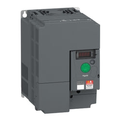
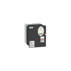
Variable speed drive ATV310, 11 kW, 15 hp, 380...460 V, 3 phase
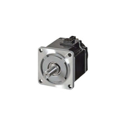
1S AC servo motor 400 W 230 VAC 3000 rpm 1.27 Nm absolute encoder
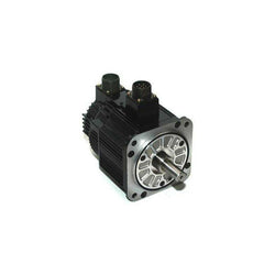
Servo Motor, 1300W, 8.34Nm, 5.4A, 1500rpm
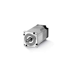
AC DC & Servo Motors 400W 3KRPM INC EY GSrvMtr
Motor Drives G5 ECAT Servo Drive 750W 200VA


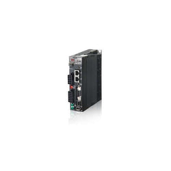
The SGD7S2R8A30A is an advanced SIGMA-7 servo amplifier optimized for 200V power systems, offering a robust output of 0.40 kW in a three-phase 230V setup. This model supports MECHATROLINK III communication through an RJ45 connector, enabling seamless integration into automation frameworks. Designed for high reliability, the SGD7S2R8A30A excels in precision motion control applications across various industrial settings.

Variable Speed Drive Altivar ATV320 - 1.1kW - 200...240V - 1 Phase - compact
Main
| Characteristic | Value(s) |
|---|---|
| Range of Product | Altivar 61 |
| Product or Component Type | Variable speed drive |
| Product Specific Application | Pumping and ventilation machine |
| Component name | ATV61 |
| Motor power kW | 75 kW, 3 phase 380...480 V |
| Maximum Horse Power Rating | 100 hp, 3 phase 380...480 V |
| power supply voltage | 380...480 V - 15...10 % |
| supply number of phases | 3 phase |
| Line current | 137 A 480 V 3 phase 75 kW / 100 hp 167 A 380 V 3 phase 75 kW / 100 hp |
| EMC filter | Level 3 EMC filter |
| Assembly style | With heat sink |
| Apparent power | 109.9 kVA 380 V 3 phase 75 kW / 100 hp |
| maximum prospective line Isc | 22 kA 3 phase |
| Maximum transient current | 192 A 60 s, 3 phase |
| Nominal switching frequency | 12 kHz |
| Switching frequency | 1...16 kHz adjustable 12...16 kHz with derating factor |
| asynchronous motor control | Voltage/frequency ratio - Energy Saving, quadratic U/f Voltage/frequency ratio, 5 points Flux vector control without sensor, standard Voltage/frequency ratio, 2 points |
| Synchronous motor control profile | Vector control without sensor, standard |
| Communication Port Protocol | CANopen Modbus |
| Type of polarization | No impedance Modbus |
| Option card | Communication card APOGEE FLN Communication card BACnet Communication card CC-Link Controller inside programmable card Communication card DeviceNet Communication card EtherNet/IP Communication card Fipio I/O extension card Communication card Interbus-S Communication card LonWorks Communication card METASYS N2 Communication card Modbus Plus Communication card Modbus TCP Communication card Modbus/Uni-Telway Multi-pump card Communication card Profibus DP Communication card Profibus DP V1 |
Complementary
| Characteristic | Value(s) |
|---|---|
| Product destination | Asynchronous motors Synchronous motors |
| power supply voltage limits | 323â¦528 V |
| power supply frequency | 50...60 Hz - 5...5 % |
| power supply frequency limits | 47.5...63 Hz |
| Continuous output current | 124 A 12 kHz, 460 V - 3 phase 160 A 12 kHz, 380 V - 3 phase |
| Output frequency | 0.1â¦500 Hz |
| Speed range | 1â¦100 in open-loop mode, without speed feedback |
| Speed accuracy | +/- 10 % of nominal slip 0.2 Tn to Tn without speed feedback |
| Torque accuracy | +/- 15 % in open-loop mode, without speed feedback |
| Transient overtorque | 130 % of nominal motor torque +/- 10 % 60 s |
| Braking torque | <= 125 % with braking resistor 30 % without braking resistor |
| Regulation loop | Frequency PI regulator |
| Motor slip compensation | Adjustable Not available in voltage/frequency ratio (2 or 5 points) Can be suppressed Automatic whatever the load |
| diagnostic | 1 LED (red) for drive voltage |
| Output voltage | <= power supply voltage |
| electrical isolation | Between power and control terminals |
| type of cable for mounting in an enclosure | With an IP21 or an IP31 kit 3 IEC cable 104 °F (40 °C), copper 70 °C / PVC With UL Type 1 kit 3 UL 508 cable 104 °F (40 °C), copper 75 °C / PVC Without mounting kit 1 IEC cable 113 °F (45 °C), copper 70 °C / PVC Without mounting kit 1 IEC cable 113 °F (45 °C), copper 90 °C / XLPE/EPR |
| Electrical connection | Terminal 2.5 mm² / AWG 14 AI1-/AI1+, AI2, AO1, R1A, R1B, R1C, R2A, R2B, LI1...LI6, PWR) Terminal 150 mm² / 300 kcmil L1/R, L2/S, L3/T, U/T1, V/T2, W/T3, PC/-, PO, PA/+, PA, PB) |
| Tightening torque | 5.3 lbf.in (0.6 N.m) AI1-/AI1+, AI2, AO1, R1A, R1B, R1C, R2A, R2B, LI1...LI6, PWR) 362.9 lbf.in (41 N.m), 360 lb.in L1/R, L2/S, L3/T, U/T1, V/T2, W/T3, PC/-, PO, PA/+, PA, PB) |
| Supply | Internal supply for reference potentiometer (1 to 10 kOhm) 10.5 V DC, +/- 5 %, <10 mA overload and short-circuit protection Internal supply 24 V DC 21â¦27 V), <200 mA overload and short-circuit protection External supply 24 V DC 19â¦30 V) |
| Analogue input number | 2 |
| Analogue input type | AI1-/Al1+ bipolar differential voltage +/- 10 V DC 24 V max 11 bits + sign AI2 software-configurable current 0...20 mA 242 Ohm 11 bits AI2 software-configurable voltage 0...10 V DC 24 V max 30000 Ohm 11 bits |
| sampling time | 2 ms +/- 0.5 ms AI1-/Al1+) - analog input 2 ms +/- 0.5 ms Al2) - analog input 2 ms +/- 0.5 ms AO1) - analog output 2 ms +/- 0.5 ms LI1...LI5) - discrete input 2 ms +/- 0.5 ms LI6)if configured as logic input - discrete input |
| absolute accuracy precision | +/- 0.6 % AI1-/Al1+) for a temperature variation 60 °C +/- 0.6 % AI2) for a temperature variation 60 °C +/- 1 % AO1) for a temperature variation 60 °C |
| Linearity error | +/- 0.15 % of maximum value AI1-/Al1+) +/- 0.15 % of maximum value AI2) +/- 0.2 % AO1) |
| Analogue output number | 1 |
| Analogue output type | AO1 software-configurable current 0...20 mA 500 Ohm 10 bits AO1 software-configurable voltage 0...10 V DC 470 Ohm 10 bits AO1 software-configurable logic output 10 V, 20 mA |
| Discrete output number | 2 |
| Discrete output type | Configurable relay logic R1A, R1B, R1C) NO/NC - 100000 cycles Configurable relay logic R2A, R2B) NO - 100000 cycles |
| maximum response time | <= 100 ms in STO (Safe Torque Off) R1A, R1B, R1C <= 7 ms +/- 0.5 ms R2A, R2B <= 7 ms +/- 0.5 ms |
| Minimum switching current | 3 mA 24 V DC configurable relay logic |
| Maximum switching current | R1, R2 2 A 250 V AC inductive, cos phi = 0.4 7 ms R1, R2 2 A 30 V DC inductive, cos phi = 0.4 7 ms R1, R2 5 A 250 V AC resistive, cos phi = 1 0 ms R1, R2 5 A 30 V DC resistive, cos phi = 1 0 ms |
| Discrete input number | 7 |
| Discrete input type | Programmable LI1...LI5) 24 V DC <= 30 V)level 1 PLC - 3500 Ohm Switch-configurable LI6) 24 V DC <= 30 V)level 1 PLC - 3500 Ohm Switch-configurable PTC probe LI6)0â¦6 - 1500 Ohm Safety input PWR) 24 V DC <= 30 V) - 1500 Ohm |
| Discrete input logic | Negative logic (sink) LI1...LI5), > 16 V, < 10 V Positive logic (source) LI1...LI5), < 5 V, > 11 V Negative logic (sink) LI6)if configured as logic input, > 16 V, < 10 V Positive logic (source) LI6)if configured as logic input, < 5 V, > 11 V |
| Acceleration and deceleration ramps | Linear adjustable separately from 0.01 to 9000 s S, U or customized Automatic adaptation of ramp if braking capacity exceeded, by using resistor |
| Braking to standstill | By DC injection |
| Protection type | Against exceeding limit speed drive Against input phase loss drive Break on the control circuit drive Input phase breaks drive Line supply overvoltage drive Line supply undervoltage drive Overcurrent between output phases and earth drive Overheating protection drive Overvoltages on the DC bus drive Power removal drive Short-circuit between motor phases drive Thermal protection drive Motor phase break motor Power removal motor Thermal protection motor |
| Insulation resistance | > 1 mOhm 500 V DC for 1 minute to earth |
| Frequency resolution | Analog input 0.024/50 Hz Display unit 0.1 Hz |
| Connector type | 1 RJ45 on front face)Modbus 1 RJ45 on terminal)Modbus Male SUB-D 9 on RJ45CANopen |
| Physical interface | 2-wire RS 485 Modbus |
| Transmission frame | RTU Modbus |
| Transmission rate | 4800 bps, 9600 bps, 19200 bps, 38.4 Kbps Modbus on terminal 9600 bps, 19200 bps Modbus on front face 20 kbps, 50 kbps, 125 kbps, 250 kbps, 500 kbps, 1 Mbps CANopen |
| Data format | 8 bits, 1 stop, even parity Modbus on front face 8 bits, odd even or no configurable parity Modbus on terminal |
| Number of addresses | 1â¦127 CANopen 1â¦247 Modbus |
| Method of access | Slave CANopen |
| Marking | CE |
| Operating position | Vertical +/- 10 degree |
| Product Weight | 97.003 lb(US) (44 kg) |
| Width | 12.6 in (320 mm) |
| Height | 24.8 in (630 mm) |
| Depth | 11.4 in (290 mm) |
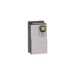
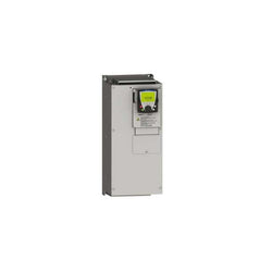
Variable Speed Drive ATV630 - 160kW/250hp - 380...480V - IP00
This Altivar Process ATV600 variable speed drive can feed 3-phase synchronous and asynchronous power motors. It features 3 built-in RJ45 communication ports as standard, 1 Ethernet port, 2 serial ports. It works at a rated supply voltage from 380V to 480V AC. This drive provides up to 30% energy saving when on standby due to the innovative ââStop and Goââoperation without additional costs. It is suitable for motors with power rating up to 250kW / 400hp for applications requiring slight overload (up to 120%). It is suitable for motors with power rating up to 220kW / 300hp for applications requiring significant overload (up to 150%). It weighs 203kg and its dimensions are, 598mm wide, 1195mm high, 380mm deep. This drive is focused on fluids management processing and energy saving, it offers extensive flexibility in water and wastewater, mining, minerals and metals, oil and gas and food and beverage applications. Accessories (fan kit, graphic display terminal) and options (I/O expansion modules, communication modules, EMC input filters) are available with Altivar Process ATV600 drives, depending on the drive rating. It is designed to be mounted in vertical position (+/- 10 °) on a wall. This new concept of drives meets the major needs of process and utilities in terms of equipment efficiency and total cost of ownership by supporting the energy management, asset management and also the overall performance of the process.
Main
| Characteristic | Value(s) |
|---|---|
| Range of Product | Altivar Process ATV600 |
| Product Specific Application | Process and utilities |
| Product or Component Type | Variable speed drive |
| Variant | Standard version |
| Device short name | ATV630 |
| Mounting Mode | Wall mount |
| Communication Port Protocol | Modbus TCP Modbus serial Ethernet |
| [Us] rated supply voltage | 380...480 V - 15...10 % |
| [Us] rated supply voltage | 380...480 V |
| Relative symmetric mains voltage tolerance | 10 % |
| Relative symmetric network frequency tolerance | 5 % |
| nominal output current | 481.0 A |
| IP degree of protection | IP21 |
| Product destination | Asynchronous motors Synchronous motors |
| EMC filter | Integrated 164.04 ft (50 m) IEC 61800-3 category C3 |
| IP degree of protection | IP00IEC 61800-5-1 IP00IEC 60529 IP21 with kit VW3A9113)IEC 61800-5-1 IP21 with kit VW3A9113)IEC 60529 |
| type of cooling | Forced convection |
| Supply frequency | 50...60 Hz - 5...5 % |
| Motor power kW | 250 kW normal duty) 220 kW heavy duty) |
| Maximum Horse Power Rating | 400 hp normal duty 300 hp heavy duty |
| Line current | 451 A 380 V normal duty) 366 A 480 V normal duty) 365 A 380 V heavy duty) 301 A 480 V heavy duty) |
| Continuous output current | 481 A 2.5 kHz normal duty 387 A 2.5 kHz heavy duty |
| Speed drive output frequency | 0.1â¦500 Hz |
| Safety function | STO (safe torque off) SIL 3 |
| Option card | Slot A communication module, Profibus DP V1 Slot A communication module, PROFINET Slot A communication module, DeviceNet Slot A communication module, Modbus TCP/EtherNet/IP Slot A communication module, CANopen daisy chain RJ45 Slot A communication module, CANopen SUB-D 9 Slot A communication module, CANopen screw terminals Slot A/slot B digital and analog I/O extension module Slot A/slot B output relay extension module Slot A communication module, Ethernet IP/Modbus TCP/MD-Link communication module, BACnet MS/TP communication module, Ethernet Powerlink |
Complementary
| Characteristic | Value(s) |
|---|---|
| Discrete input number | 8 |
| Discrete input type | DI7, DI8 programmable as pulse input 0â¦30 kHz, 24 V DC <= 30 V) |
| Discrete input logic | 16 preset speeds |
| Discrete output number | 0 |
| Discrete output type | Relay outputs R1A, R1B, R1C 250 V AC 3000 mA Relay outputs R1A, R1B, R1C 30 V DC 3000 mA Relay outputs R2A, R2C 250 V AC 5000 mA Relay outputs R2A, R2C 30 V DC 5000 mA Relay outputs R3A, R3C 250 V AC 5000 mA Relay outputs R3A, R3C 30 V DC 5000 mA |
| Analogue input number | 3 |
| Analogue input type | AI1, AI2, AI3 software-configurable voltage 0...10 V DC 31.5 kOhm 12 bits AI1, AI2, AI3 software-configurable current 0...20 mA 250 Ohm 12 bits AI2 voltage analog input - 10...10 V DC 31.5 kOhm 12 bits |
| Analogue output number | 2 |
| Analogue output type | Software-configurable voltage AQ1, AQ2 0...10 V DC 470 Ohm 10 bits Software-configurable current AQ1, AQ2 0...20 mA 10 bits Software-configurable current DQ-, DQ+ 30 V DC Software-configurable current DQ-, DQ+ 100 mA |
| Relay output number | 3 |
| Relay output type | Configurable relay logic R1 fault relay NO/NC 100000 cycles Configurable relay logic R2 sequence relay NO 100000 cycles Configurable relay logic R3 sequence relay NO 100000 cycles |
| Maximum switching current | Relay output R1, R2, R3 resistive, cos phi = 1 3 A 250 V AC Relay output R1, R2, R3 resistive, cos phi = 1 3 A 30 V DC Relay output R1, R2, R3 inductive, cos phi = 0.4 7 ms 2 A 250 V AC Relay output R1, R2, R3 inductive, cos phi = 0.4 7 ms 2 A 30 V DC |
| Minimum switching current | Relay output R1, R2, R3 5 mA 24 V DC |
| Phase | 3 phase |
| Physical interface | Ethernet 2-wire RS 485 |
| Method of access | Slave Modbus TCP |
| Transmission Rate | 10, 100 Mbits 4800 bps, 9600 bps, 19200 bps, 38.4 Kbps |
| Transmission frame | RTU |
| Output voltage | <= power supply voltage |
| Permissible temporary current boost | 1.1 x In 60 s normal duty) 1.5 x In 60 s heavy duty) |
| Data format | 8 bits, configurable odd, even or no parity |
| Type of polarization | No impedance |
| Frequency resolution | Display unit 0.1 Hz Analog input 0.012/50 Hz |
| Electrical connection | Control removable screw terminals 0.5...1.5 mm² AWG 20...AWG 16 Line side screw terminal 4 x 185 mm² 3 x 350 kcmil Motor screw terminal 4 x 185 mm² 3 x 350 kcmil |
| Connector type | RJ45 on the remote graphic terminal)Ethernet/Modbus TCP RJ45 on the remote graphic terminal)Modbus serial |
| Exchange mode | Half duplex, full duplex, autonegotiation Ethernet/Modbus TCP |
| Number of addresses | 1â¦247 Modbus serial |
| Supply | External supply for digital inputs 24 V DC 19â¦30 V), <1.25 mA overload and short-circuit protection Internal supply for reference potentiometer (1 to 10 kOhm) 10.5 V DC +/- 5 %, <10 mA overload and short-circuit protection Internal supply for digital inputs and STO 24 V DC 21â¦27 V), <200 mA overload and short-circuit protection |
| Local signalling | 3 LEDs for local diagnostic 3 LEDs (dual colour) for embedded communication status 4 LEDs (dual colour) for communication module status 1 LED (red) for presence of voltage |
| Input compatibility | DI1...DI6 discrete input level 1 PLC IEC 61131-2 DI5, DI6 discrete input level 1 PLC IEC 65A-68 STOA, STOB discrete input level 1 PLC IEC 61131-2 |
| Discrete input logic | Positive logic (source) DI1...DI8), < 5 V, > 11 V Negative logic (sink) DI1...DI8), > 16 V, < 10 V |
| Sampling duration | 2 ms +/- 0.5 ms DI1...DI4) - discrete input 5 ms +/- 1 ms DI5, DI6) - discrete input 5 ms +/- 0.1 ms AI1, AI2, AI3) - analog input 10 ms +/- 1 ms AO1) - analog output |
| Accuracy | +/- 0.6 % AI1, AI2, AI3 for a temperature variation 60 °C analog input +/- 1 % AO1, AO2 for a temperature variation 60 °C analog output |
| Linearity error | AI1, AI2, AI3 +/- 0.15 % of maximum value analog input AO1, AO2 +/- 0.2 % analog output |
| Refresh time | Relay output R1, R2, R3)5 ms +/- 0.5 ms) |
| Isolation | Between power and control terminals |
| Discrete and process manufacturing | Building - HVAC compressor centrifugal Food and beverage processing other application Mining mineral and metal fan Mining mineral and metal pump Oil and gas fan Water and waste water other application Building - HVAC screw compressor Food and beverage processing pump Food and beverage processing fan Food and beverage processing atomization Oil and gas electro submersible pump (ESP) Oil and gas water injection pump Oil and gas jet fuel pump Oil and gas compressor for refinery Water and waste water centrifuge pump Water and waste water positive displacement pump Water and waste water electro submersible pump (ESP) Water and waste water screw pump Water and waste water lobe compressor Water and waste water screw compressor Water and waste water compressor centrifugal Water and waste water fan Water and waste water conveyor Water and waste water mixer |
| Power range | 250â¦500 kW 380â¦440 V 3 phase 250â¦500 kW 480â¦500 V 3 phase |
| Enclosure mounting | Wall mounted |
| 4 quadrant operation possible | False |
| Asynchronous motor control profile | Variable torque standard Constant torque standard Optimized torque mode |
| Synchronous motor control profile | Permanent magnet motor Synchronous reluctance motor |
| Maximum output frequency | 500 kHz |
| Acceleration and deceleration ramps | Linear adjustable separately from 0.01...9999 s |
| Motor slip compensation | Automatic whatever the load Adjustable Not available in permanent magnet motor law Can be suppressed |
| Switching frequency | 2.5...8 kHz with derating factor 2...8 kHz adjustable |
| Nominal switching frequency | 2.5 kHz |
| Braking to standstill | By DC injection |
| Brake chopper integrated | False |
| Maximum Input Current per Phase | 451.0 A |
| Maximum output voltage | 480.0 V |
| Apparent power | 279 kVA 480 V normal duty) 229 kVA 480 V heavy duty) |
| Maximum transient current | 529 A 60 s normal duty) 581 A 60 s heavy duty) |
| Network Frequency | 50-60 Hz |
| Prospective line Isc | 50 kA |
| Base load current at high overload | 387.0 A |
| Base load current at low overload | 481.0 A |
| Power dissipation in W | Forced convection 5773 W Natural convection 606 W 380 V 2.5 kHz |
| With safety function Safely Limited Speed (SLS) | False |
| With safety function Safe brake management (SBC/SBT) | False |
| With safety function Safe Operating Stop (SOS) | False |
| With safety function Safe Position (SP) | False |
| With safety function Safe programmable logic | False |
| With safety function Safe Speed Monitor (SSM) | False |
| With safety function Safe Stop 1 (SS1) | False |
| With sft fct Safe Stop 2 (SS2) | False |
| With safety function Safe torque off (STO) | True |
| With safety function Safely Limited Position (SLP) | False |
| With safety function Safe Direction (SDI) | False |
| Protection type | Thermal protection motor Safe torque off motor Motor phase break motor Thermal protection drive Safe torque off drive Overheating drive Overcurrent between output phases and earth drive Overload of output voltage drive Short-circuit protection drive Motor phase break drive Overvoltages on the DC bus drive Line supply overvoltage drive Line supply undervoltage drive Line supply phase loss drive Overspeed drive Break on the control circuit drive |
| Quantity per Set | 1 |
| Width | 23.5 in (598 mm) |
| Height | 47.05 in (1195 mm) |
| Depth | 15.0 in (380 mm) |
| Product Weight | 447.5 lb(US) (203 kg) |
Variable Speed Drive Altivar 61 - 18.5kW 25hp - 380...480V - IP20

Variable speed drive ATV310, 0.75 kW, 1 hp, 380...460 V, 3 phase
Main
| Characteristic | Value(s) |
|---|---|
| Range of Product | Altivar |
| Product or Component Type | Variable speed drive |
| Product Specific Application | Simple machine |
| Component name | ATV31 |
| Assembly style | With heat sink |
| EMC filter | Integrated |
| [Us] rated supply voltage | 380...500 V - 5...5 % |
| Supply frequency | 50...60 Hz - 5...5 % |
| Phase | 3 phase |
| Motor power kW | 0.75 kW 4 kHz |
| Maximum Horse Power Rating | 1 hp 4 kHz |
| Line current | 2.7 A 500 V 3.6 A 380 V, Isc = 1 kA |
| Apparent power | 2.4 kVA |
| Prospective line Isc | 1 kA |
| Nominal output current | 2.3 A 4 kHz |
| Maximum transient current | 3.5 A 60 s |
| Power dissipation in W | 41 W at nominal load |
| Asynchronous motor control profile | Sensorless flux vector control with PWM type motor control signal Factory set : constant torque |
| Analogue input number | 3 |
Complementary
| Characteristic | Value(s) |
|---|---|
| Product destination | Asynchronous motors |
| Supply voltage limits | 323â¦550 V |
| Network Frequency | 47.5...63 Hz |
| Output frequency | 0.0005â¦0.5 kHz |
| Nominal switching frequency | 4 kHz |
| Switching frequency | 2...16 kHz adjustable |
| Speed range | 1â¦50 |
| Transient overtorque | 150â¦170 % of nominal motor torque |
| Braking torque | <= 150 % 60 s with braking resistor 100 % with braking resistor continuously 150 % without braking resistor |
| Regulation loop | Frequency PI regulator |
| Motor slip compensation | Adjustable Automatic whatever the load Suppressable |
| Output voltage | <= power supply voltage |
| Electrical connection | Al1, Al2, Al3, AOV, AOC, R1A, R1B, R1C, R2A, R2B, LI1...LI6 terminal 0.004 in² (2.5 mm²) AWG 14 L1, L2, L3, U, V, W, PA, PB, PA/+, PC/- terminal 0.004 in² (2.5 mm²) AWG 14 |
| Tightening torque | Al1, Al2, Al3, AOV, AOC, R1A, R1B, R1C, R2A, R2B, LI1...LI6 5.3 lbf.in (0.6 N.m) L1, L2, L3, U, V, W, PA, PB, PA/+, PC/- 7.08 lbf.in (0.8 N.m) |
| Insulation | Electrical between power and control |
| Supply | Internal supply for logic inputs 19...30 V 100 mA overload and short-circuit protection Internal supply for reference potentiometer (2.2 to 10 kOhm) 10...10.8 V 10 mA overload and short-circuit protection |
| Analogue input type | AI3 configurable current 0...20 mA 250 Ohm AI1 configurable voltage 0...10 V 30 V max 30000 Ohm AI2 configurable voltage +/- 10 V 30 V max 30000 Ohm |
| Sampling duration | LI1...LI6 4 ms discrete AI1, AI2, AI3 8 ms analog |
| Response time | AOV, AOC 8 ms analog R1A, R1B, R1C, R2A, R2B 8 ms discrete |
| Linearity error | +/- 0.2 % output |
| Analogue output number | 2 |
| Analogue output type | AOC configurable current 0...20 mA 800 Ohm 8 bits AOV configurable voltage 0...10 V 470 Ohm 8 bits |
| Discrete input logic | Positive logic (source) LI1...LI6), < 5 V, > 11 V Logic input not wired LI1...LI4), < 13 V Negative logic (source) LI1...LI6), > 19 V |
| Discrete output number | 2 |
| Discrete output type | Configurable relay logic R1A, R1B, R1C) 1 NO + 1 NC - 100000 cycles Configurable relay logic R2A, R2B) NC - 100000 cycles |
| Minimum switching current | R1-R2 10 mA 5 V DC |
| Maximum switching current | R1-R2 2 A 250 V AC inductive, cos phi = 0.4 7 ms R1-R2 2 A 30 V DC inductive, cos phi = 0.4 7 ms R1-R2 5 A 250 V AC resistive, cos phi = 1 0 ms R1-R2 5 A 30 V DC resistive, cos phi = 1 0 ms |
| Discrete input number | 6 |
| Discrete input type | LI1...LI6) programmable 24 V, 0â¦100 mA PLC 3500 Ohm |
| Acceleration and deceleration ramps | S, U or customized Linear adjustable separately from 0.1 to 999.9 s |
| Braking to standstill | By DC injection |
| Protection type | Input phase breaks drive Line supply overvoltage and undervoltage safety circuits drive Line supply phase loss safety function, for three phases supply drive Motor phase breaks drive Overcurrent between output phases and earth (on power up only) drive Overheating protection drive Short-circuit between motor phases drive Thermal protection motor |
| Insulation resistance | >= 500 mOhm 500 V DC for 1 minute |
| Display type | 1 LED Red)drive voltage Four 7-segment display unitsCANopen bus status |
| Time constant | 5 ms for reference change |
| Frequency resolution | Display unit 0.1 Hz Analog input 0.1...100 Hz |
| Connector type | 1 RJ45 CANopen via VW3 CANTAP2 adaptor 1 RJ45 Modbus |
| Physical interface | RS485 multidrop serial link CANopen via VW3 CANTAP2 adaptor RS485 multidrop serial link Modbus |
| Transmission frame | RTU CANopen via VW3 CANTAP2 adaptor RTU Modbus |
| Transmission Rate | 10, 20, 50, 125, 250, 500 kbps or 1 Mbps CANopen via VW3 CANTAP2 adaptor 4800, 9600 or 19200 bps Modbus |
| Number of addresses | 1â¦127 CANopen via VW3 CANTAP2 adaptor 1â¦247 Modbus |
| Number of drive | 127 CANopen via VW3 CANTAP2 adaptor 31 Modbus |
| Marking | CE |
| Operating position | Vertical +/- 10 degree |
| Product Weight | 4.0 lb(US) (1.8 kg) |

PLC Direct is not an authorized distributor. We offer a broad range of in-stock products with minimal lead time.

PLC Direct is not an authorized distributor. We offer a broad range of in-stock products with minimal lead time.

PLC Direct is not an authorized distributor. We offer a broad range of in-stock products with minimal lead time.

PLC Direct is not an authorized distributor. We offer a broad range of in-stock products with minimal lead time.

PLC Direct is not an authorized distributor. We offer a broad range of in-stock products with minimal lead time.

Variable Speed Drive Altivar 61 - 250kW 400hp - 460V
This Altivar 212 variable speed drive can feed 3-phase asynchronous motors. Its protection index is IP21. It works at a rated power up to 4kW / 5hp and a rated voltage from 200V to 240V AC. Its design is based on eco-energy with a reduction in energy consumption of up to 70% compared to a conventional control system. Thanks to its cable temperature rise reduction technology, the Altivar 212 drive offers immediate, disturbance-free operation avoiding additional options such as a line choke or DC choke to deal with current harmonics. It weighs 3.05kg and its dimensions are, 142mm wide, 184mm high, 150mm deep. It is specifically designed for the most common fluid management applications in tertiary sector buildings (HVAC) like heating, ventilation, air conditioning and pumping. It conforms to international standards IEC/EN 61800-5-1 and IEC/EN 61800-3 (immunity and conducted and radiated EMC emissions). It is also CE, UL, CSA, C-Tick and NOM certified. The Altivar 212 offers optional motor chokes which can increase the maximum cable lengths between the drive and the motor and limit disturbance at the motor terminals. It is designed to be mounted in vertical position (+/- 10 °) on a panel, thanks to 4 fixing holes. The Altivar 212 drive can easily be adapted to all building management systems thanks to its numerous functions and communication protocols integrated as standard, Modbus, METASYS N2, APOGEE FLN P1 and BACnet.
Main
| Characteristic | Value(s) |
|---|---|
| Device short name | ATV212 |
| Product destination | Asynchronous motors |
| Phase | 3 phase |
| Motor power kW | 4 kW |
| Maximum Horse Power Rating | 5 hp |
| Supply voltage limits | 170â¦264 V |
| Supply frequency | 50...60 Hz - 5...5 % |
| Line current | 13 A 240 V 15.7 A 200 V |
| Range of Product | Altivar 212 |
| Product or Component Type | Variable speed drive |
| Product Specific Application | Pumps and fans in HVAC |
| Communication Port Protocol | LonWorks METASYS N2 APOGEE FLN Modbus BACnet |
| [Us] rated supply voltage | 200...240 V - 15...10 % |
| EMC filter | Without EMC filter |
| IP degree of protection | IP21 |
Complementary
| Characteristic | Value(s) |
|---|---|
| Apparent power | 6.7 kVA 240 V |
| Continuous output current | 17.5 A 230 V |
| Maximum transient current | 19.3 A 60 s |
| Speed drive output frequency | 0.5â¦200 Hz |
| Speed range | 1â¦10 |
| Speed accuracy | +/- 10 % of nominal slip 0.2 Tn to Tn |
| Local signalling | 1 LED (red) for DC bus energized |
| Output voltage | <= power supply voltage |
| Isolation | Electrical between power and control |
| Type of cable | Without mounting kit 1 IEC cable 113 °F (45 °C), copper 90 °C / XLPE/EPR Without mounting kit 1 IEC cable 113 °F (45 °C), copper 70 °C / PVC With UL Type 1 kit 3 UL 508 cable 104 °F (40 °C), copper 75 °C / PVC |
| Electrical connection | VIA, VIB, FM, FLA, FLB, FLC, RY, RC, F, R, RES terminal 0.004 in² (2.5 mm²) / AWG 14 L1/R, L2/S, L3/T terminal 0.009 in² (6 mm²) / AWG 10 |
| Tightening torque | 11.5 lbf.in (1.3 N.m), 11.5 lb.in L1/R, L2/S, L3/T) 5.3 lbf.in (0.6 N.m) VIA, VIB, FM, FLA, FLB, FLC, RY, RC, F, R, RES) |
| Supply | Internal supply for reference potentiometer (1 to 10 kOhm) 10.5 V DC +/- 5 %, <10 A overload and short-circuit protection Internal supply 24 V DC 21â¦27 V), <200 A overload and short-circuit protection |
| Sampling duration | 2 ms +/- 0.5 ms F discrete 2 ms +/- 0.5 ms R discrete 2 ms +/- 0.5 ms RES discrete 3.5 ms +/- 0.5 ms VIA analog 22 ms +/- 0.5 ms VIB analog |
| Response time | FM 2 ms +/- 0.5 ms analog FLA, FLC 7 ms +/- 0.5 ms discrete FLB, FLC 7 ms +/- 0.5 ms discrete RY, RC 7 ms +/- 0.5 ms discrete |
| Accuracy | +/- 0.6 % VIA) for a temperature variation 60 °C +/- 0.6 % VIB) for a temperature variation 60 °C +/- 1 % FM) for a temperature variation 60 °C |
| Linearity error | VIA +/- 0.15 % of maximum value input VIB +/- 0.15 % of maximum value input FM +/- 0.2 % output |
| Analogue output type | FM switch-configurable voltage 0...10 V DC 7620 Ohm 10 bits FM switch-configurable current 0...20 mA 970 Ohm 10 bits |
| Discrete output type | Configurable relay logic FLA, FLC) NO - 100000 cycles Configurable relay logic FLB, FLC) NC - 100000 cycles Configurable relay logic RY, RC) NO - 100000 cycles |
| Minimum switching current | 3 mA 24 V DC configurable relay logic |
| Maximum switching current | 5 A 250 V AC resistive cos phi = 1 L/R = 0 ms FL, R) 5 A 30 V DC resistive cos phi = 1 L/R = 0 ms FL, R) 2 A 250 V AC inductive cos phi = 0.4 L/R = 7 ms FL, R) 2 A 30 V DC inductive cos phi = 0.4 L/R = 7 ms FL, R) |
| Discrete input type | F programmable 24 V DC level 1 PLC 4700 Ohm R programmable 24 V DC level 1 PLC 4700 Ohm RES programmable 24 V DC level 1 PLC 4700 Ohm |
| Discrete input logic | Positive logic (source) F, R, RES), <= 5 V, >= 11 V Negative logic (sink) F, R, RES), >= 16 V, <= 10 V |
| Dielectric strength | 2830 V DC between earth and power terminals 4230 V DC between control and power terminals |
| Insulation resistance | >= 1 mOhm 500 V DC for 1 minute |
| Frequency resolution | Display unit 0.1 Hz Analog input 0.024/50 Hz |
| Communication Service | Read device identification (43) Write single register (06) Read holding registers (03) 2 words maximum Time out setting from 0.1 to 100 s Write multiple registers (16) 2 words maximum Monitoring inhibitable |
| Option card | Communication card LonWorks |
| Power dissipation in W | 193 W |
| air flow | 17435.7 Gal/hr(US) (66 m3/h) |
| Specific application | HVAC |
| Variable speed drive application selection | Building - HVAC compressor for scroll Building - HVAC fan Building - HVAC pump |
| Motor power range AC-3 | 4â¦6 kW 200â¦240 V 3 phase |
| Motor starter type | Variable speed drive |
| Discrete output number | 2 |
| Analogue input number | 2 |
| Analogue input type | VIA switch-configurable voltage 0...10 V DC 24 V max 30000 Ohm 10 bits VIB configurable voltage 0...10 V DC 24 V max 30000 Ohm 10 bits VIB configurable PTC probe 0...6 probes 1500 Ohm VIA switch-configurable current 0...20 mA 250 Ohm 10 bits |
| Analogue output number | 1 |
| Physical interface | 2-wire RS 485 |
| Connector Type | 1 RJ45 1 open style |
| Transmission Rate | 9600 bps or 19200 bps |
| Transmission frame | RTU |
| Number of addresses | 1â¦247 |
| Data format | 8 bits, 1 stop, odd even or no configurable parity |
| Type of polarization | No impedance |
| Asynchronous motor control profile | Voltage/frequency ratio, 2 points Voltage/frequency ratio, 5 points Flux vector control without sensor, standard Voltage/frequency ratio, automatic IR compensation (U/f + automatic Uo) Voltage/frequency ratio - Energy Saving, quadratic U/f |
| Torque accuracy | +/- 15 % |
| Transient overtorque | 120 % of nominal motor torque +/- 10 % 60 s |
| Acceleration and deceleration ramps | Linear adjustable separately from 0.01 to 3200 s Automatic based on the load |
| Motor slip compensation | Automatic whatever the load Not available in voltage/frequency ratio motor control Adjustable |
| Switching frequency | 6...16 kHz adjustable 12...16 kHz with derating factor |
| Nominal switching frequency | 12 kHz |
| Braking to standstill | By DC injection |
| Network Frequency | 47.5...63 Hz |
| Prospective line Isc | 5 kA |
| Protection type | Overheating protection drive Thermal power stage drive Short-circuit between motor phases drive Input phase breaks drive Overcurrent between output phases and earth drive Overvoltages on the DC bus drive Break on the control circuit drive Against exceeding limit speed drive Line supply overvoltage and undervoltage drive Line supply undervoltage drive Against input phase loss drive Thermal protection motor Motor phase break motor With PTC probes motor |
| Width | 5.6 in (142 mm) |
| Height | 7.2 in (184 mm) |
| Depth | 5.9 in (150 mm) |
| Product Weight | 6.72 lb(US) (3.05 kg) |

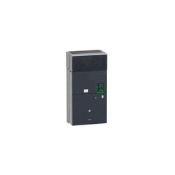
This Altivar Process ATV600 variable speed drive can feed 3-phase synchronous and asynchronous power motors. It features 3 built-in RJ45 communication ports as standard, 1 Ethernet port, 2 serial ports. It works at a rated supply voltage from 200V to 240V AC. This drive provides up to 30% energy saving when on standby due to the innovative ââStop and Goââoperation without additional costs. It is suitable for motors with power rating up to 75kW / 100hp for applications requiring slight overload (up to 120%). It is suitable for motors with power rating up to 55kW / 75hp for applications requiring significant overload (up to 150%). It weighs 84kg and its dimensions are, 320mm wide, 852mm high, 390mm deep. This drive is focused on fluids management processing and energy saving, it offers extensive flexibility in water and wastewater, mining, minerals and metals, oil and gas and food and beverage applications. Accessories (fan kit, graphic display terminal) and options (I/O expansion modules, communication modules, EMC input filters) are available with Altivar Process ATV600 drives, depending on the drive rating. It is designed to be mounted in vertical position (+/- 10 °) on a wall. This new concept of drives meets the major needs of process and utilities in terms of equipment efficiency and total cost of ownership by supporting the energy management, asset management and also the overall performance of the process.
Main
| Characteristic | Value(s) |
|---|---|
| Range of Product | Altivar Process ATV600 |
| Product Specific Application | Process and utilities |
| Product or Component Type | Variable speed drive |
| Variant | Standard version |
| Device short name | ATV630 |
| Mounting Mode | Wall mount |
| Communication Port Protocol | Modbus serial Ethernet Modbus TCP |
| [Us] rated supply voltage | 200...240 V - 15...10 % |
| [Us] rated supply voltage | 200...240 V |
| Relative symmetric mains voltage tolerance | 10 % |
| Relative symmetric network frequency tolerance | 5 % |
| nominal output current | 282.0 A |
| IP degree of protection | IP21 |
| Product destination | Asynchronous motors Synchronous motors |
| EMC filter | Without EMC filter |
| IP degree of protection | IP00IEC 61800-5-1 IP00IEC 60529 IP21 with kit VW3A9704)IEC 61800-5-1 IP21 with kit VW3A9704)IEC 60529 |
| type of cooling | Forced convection |
| Supply frequency | 50...60 Hz - 5...5 % |
| Motor power kW | 75 kW normal duty) 55 kW heavy duty) |
| Maximum Horse Power Rating | 100 hp normal duty 75 hp heavy duty |
| Line current | 256 A 200 V normal duty) 215 A 240 V normal duty) 189 A 200 V heavy duty) 161 A 240 V heavy duty) |
| Continuous output current | 211 A 2.5 kHz heavy duty 282 A 2.5 kHz normal duty |
| Speed drive output frequency | 0.1â¦500 Hz |
| Safety function | STO (safe torque off) SIL 3 |
| Option card | Slot A communication module, Profibus DP V1 Slot A communication module, PROFINET Slot A communication module, DeviceNet Slot A communication module, Modbus TCP/EtherNet/IP Slot A communication module, CANopen daisy chain RJ45 Slot A communication module, CANopen SUB-D 9 Slot A communication module, CANopen screw terminals Slot A/slot B digital and analog I/O extension module Slot A/slot B output relay extension module Slot A communication module, Ethernet IP/Modbus TCP/MD-Link communication module, BACnet MS/TP communication module, Ethernet Powerlink |
Complementary
| Characteristic | Value(s) |
|---|---|
| Discrete input number | 8 |
| Discrete input type | DI7, DI8 programmable as pulse input 0â¦30 kHz, 24 V DC <= 30 V) |
| Discrete input logic | 16 preset speeds |
| Discrete output number | 0 |
| Discrete output type | Relay outputs R1A, R1B, R1C 250 V AC 3000 mA Relay outputs R1A, R1B, R1C 30 V DC 3000 mA Relay outputs R2A, R2C 250 V AC 5000 mA Relay outputs R2A, R2C 30 V DC 5000 mA Relay outputs R3A, R3C 250 V AC 5000 mA Relay outputs R3A, R3C 30 V DC 5000 mA |
| Analogue input number | 3 |
| Analogue input type | AI1, AI2, AI3 software-configurable voltage 0...10 V DC 31.5 kOhm 12 bits AI1, AI2, AI3 software-configurable current 0...20 mA 250 Ohm 12 bits AI2 voltage analog input - 10...10 V DC 31.5 kOhm 12 bits |
| Analogue output number | 2 |
| Analogue output type | Software-configurable voltage AQ1, AQ2 0...10 V DC 470 Ohm 10 bits Software-configurable current AQ1, AQ2 0...20 mA 10 bits Software-configurable current DQ-, DQ+ 30 V DC Software-configurable current DQ-, DQ+ 100 mA |
| Relay output number | 3 |
| Relay output type | Configurable relay logic R1 fault relay NO/NC 100000 cycles Configurable relay logic R2 sequence relay NO 100000 cycles Configurable relay logic R3 sequence relay NO 100000 cycles |
| Maximum switching current | Relay output R1, R2, R3 resistive, cos phi = 1 3 A 250 V AC Relay output R1, R2, R3 resistive, cos phi = 1 3 A 30 V DC Relay output R1, R2, R3 inductive, cos phi = 0.4 7 ms 2 A 250 V AC Relay output R1, R2, R3 inductive, cos phi = 0.4 7 ms 2 A 30 V DC |
| Minimum switching current | Relay output R1, R2, R3 5 mA 24 V DC |
| Phase | 3 phase |
| Physical interface | Ethernet 2-wire RS 485 |
| Method of access | Slave Modbus TCP |
| Transmission Rate | 10, 100 Mbits 4800 bps, 9600 bps, 19200 bps, 38.4 Kbps |
| Transmission frame | RTU |
| Output voltage | <= power supply voltage |
| Permissible temporary current boost | 1.1 x In 60 s normal duty) 1.5 x In 60 s heavy duty) |
| Data format | 8 bits, configurable odd, even or no parity |
| Type of polarization | No impedance |
| Frequency resolution | Display unit 0.1 Hz Analog input 0.012/50 Hz |
| Electrical connection | Control removable screw terminals 0.5...1.5 mm² AWG 20...AWG 16 Line side screw terminal 2 x 95...3 x 120 mm² 2 x AWG 3/0...2 x 300 kcmil Motor screw terminal 2 x 95...3 x 120 mm² 2 x AWG 3/0...2 x 300 kcmil |
| Connector type | RJ45 on the remote graphic terminal)Ethernet/Modbus TCP RJ45 on the remote graphic terminal)Modbus serial |
| Exchange mode | Half duplex, full duplex, autonegotiation Ethernet/Modbus TCP |
| Number of addresses | 1â¦247 Modbus serial |
| Supply | External supply for digital inputs 24 V DC 19â¦30 V), <1.25 mA overload and short-circuit protection Internal supply for reference potentiometer (1 to 10 kOhm) 10.5 V DC +/- 5 %, <10 mA overload and short-circuit protection Internal supply for digital inputs and STO 24 V DC 21â¦27 V), <200 mA overload and short-circuit protection |
| Local signalling | 3 LEDs for local diagnostic 3 LEDs (dual colour) for embedded communication status 4 LEDs (dual colour) for communication module status 1 LED (red) for presence of voltage |
| Input compatibility | DI1...DI6 discrete input level 1 PLC IEC 61131-2 DI5, DI6 discrete input level 1 PLC IEC 65A-68 STOA, STOB discrete input level 1 PLC IEC 61131-2 |
| Discrete input logic | Positive logic (source) DI1...DI8), < 5 V, > 11 V Negative logic (sink) DI1...DI8), > 16 V, < 10 V |
| Sampling duration | 2 ms +/- 0.5 ms DI1...DI4) - discrete input 5 ms +/- 1 ms DI5, DI6) - discrete input 5 ms +/- 0.1 ms AI1, AI2, AI3) - analog input 10 ms +/- 1 ms AO1) - analog output |
| Accuracy | +/- 0.6 % AI1, AI2, AI3 for a temperature variation 60 °C analog input +/- 1 % AO1, AO2 for a temperature variation 60 °C analog output |
| Linearity error | AI1, AI2, AI3 +/- 0.15 % of maximum value analog input AO1, AO2 +/- 0.2 % analog output |
| Refresh time | Relay output R1, R2, R3)5 ms +/- 0.5 ms) |
| Isolation | Between power and control terminals |
| Discrete and process manufacturing | Building - HVAC compressor centrifugal Food and beverage processing other application Mining mineral and metal fan Mining mineral and metal pump Oil and gas fan Water and waste water other application Building - HVAC screw compressor Food and beverage processing pump Food and beverage processing fan Food and beverage processing atomization Oil and gas electro submersible pump (ESP) Oil and gas water injection pump Oil and gas jet fuel pump Oil and gas compressor for refinery Water and waste water centrifuge pump Water and waste water positive displacement pump Water and waste water electro submersible pump (ESP) Water and waste water screw pump Water and waste water lobe compressor Water and waste water screw compressor Water and waste water compressor centrifugal Water and waste water fan Water and waste water conveyor Water and waste water mixer |
| Power range | 55â¦100 kW 200â¦240 V 3 phase |
| Enclosure mounting | Wall mounted |
| 4 quadrant operation possible | False |
| Asynchronous motor control profile | Constant torque standard Optimized torque mode Variable torque standard |
| Synchronous motor control profile | Permanent magnet motor Synchronous reluctance motor |
| Maximum output frequency | 500 kHz |
| Acceleration and deceleration ramps | Linear adjustable separately from 0.01...9999 s |
| Motor slip compensation | Automatic whatever the load Not available in permanent magnet motor law Can be suppressed Adjustable |
| Switching frequency | 2.5...8 kHz with derating factor 2...8 kHz adjustable |
| Nominal switching frequency | 2.5 kHz |
| Braking to standstill | By DC injection |
| Brake chopper integrated | False |
| Maximum Input Current per Phase | 256.0 A |
| Maximum output voltage | 240.0 V |
| Apparent power | 83.7 kVA 240 V normal duty) 61.1 kVA 240 V heavy duty) |
| Maximum transient current | 310.2 A 60 s normal duty) 316.5 A 60 s heavy duty) |
| Network Frequency | 50-60 Hz |
| Prospective line Isc | 50 kA |
| Base load current at high overload | 211.0 A |
| Base load current at low overload | 282.0 A |
| With safety function Safely Limited Speed (SLS) | False |
| With safety function Safe brake management (SBC/SBT) | False |
| With safety function Safe Operating Stop (SOS) | False |
| With safety function Safe Position (SP) | False |
| With safety function Safe programmable logic | False |
| With safety function Safe Speed Monitor (SSM) | False |
| With safety function Safe Stop 1 (SS1) | False |
| With sft fct Safe Stop 2 (SS2) | False |
| With safety function Safe torque off (STO) | True |
| With safety function Safely Limited Position (SLP) | False |
| With safety function Safe Direction (SDI) | False |
| Protection type | Thermal protection motor Safe torque off motor Motor phase break motor Thermal protection drive Safe torque off drive Overheating drive Overcurrent between output phases and earth drive Overload of output voltage drive Short-circuit protection drive Motor phase break drive Overvoltages on the DC bus drive Line supply overvoltage drive Line supply undervoltage drive Line supply phase loss drive Overspeed drive Break on the control circuit drive |
| Quantity per Set | 1 |
| Width | 12.6 in (320 mm) |
| Height | 33.5 in (852 mm) |
| Depth | 15.4 in (390 mm) |
| Product Weight | 185.2 lb(US) (84 kg) |