
 1 year warranty

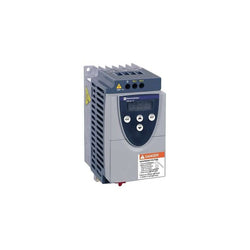
Variable speed drive ATV11 - 0.37kW - 230V 1-phase supply - IP20

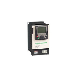
Variable Speed Drive Altivar 61 - 2.2kW 3hp 480V 3 Phases EMC IP20 with Graphic Terminal
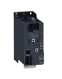
This Altivar 340 variable speed drive can feed 3-phase synchronous and asynchronous motors in open and closed loop control. Altivar Machine ATV340 drives are sized heavy duty as standard. It works at a rated power up to 7.5kW / 10hp and a rated voltage from 380V to 480V AC. ATV340 has been designed to meet the needs of applications for harsh environments, such as vibration, shock and non-conductive dust and where high temperature resistance up to 60 °C is needed. This product integrates Modbus serial line communication protocols as standard. This drive features multi-protocol Ethernet embedded, it consists of Ethernet IP and Modbus TCP communication interfaces. it weighs 3kg and its dimensions are, 110mm wide, 270mm high, 234mm deep. ATV340 incorporates functions and features suitable for the most common applications, including packaging, material handling, material working, hoisting. It conforms to international standards IEC/EN 61800-5-1 and IEC/EN 61800-3 (immunity and conducted and radiated EMC emissions), IEC 60721-3, IEC 61508, IEC 13849-1. It is also CE, UL, CSA, and TÃV certified. Accessories and options (encoder interface modules, I/O expansion modules, communication modules, braking resistors, line chokes, additional EMC filters) are available with Altivar Machine ATV340 drives, depending on the drive rating. It is designed to be mounted in vertical position (+/- 10 °) on a panel, thanks to 4 fixing holes. It is fully integrated inside Schneider Electricâs EcoStruxure Machine through DTM. It is possible to configure, control, and diagnose ATV340 drives directly in SoMachine and SoMove software by means of the same software brick (DTM).
Main
| Characteristic | Value(s) |
|---|---|
| Range of Product | Altivar Machine ATV340 |
| Product or Component Type | Variable speed drive |
| Product Specific Application | Machine |
| Mounting Mode | Cabinet mount |
| Variant | Standard version |
| Communication Port Protocol | EtherNet/IP Modbus serial Modbus TCP |
| Phase | 3 phase |
| Supply frequency | 50...60 Hz +/- 5 % |
| [Us] rated supply voltage | 380...480 V - 15...10 % |
| nominal output current | 16.5 A |
| Motor power kW | 11 kW normal duty 7.5 kW heavy duty |
| Maximum Horse Power Rating | 15 hp normal duty 10 hp heavy duty |
| EMC filter | Class C3 EMC filter integrated |
| IP degree of protection | IP20 |
Complementary
| Characteristic | Value(s) |
|---|---|
| Discrete input number | 5 |
| Discrete input type | PTI programmable as pulse input 0â¦30 kHz, 24 V DC 30 V) DI1...DI5 safe torque off, 24 V DC 30 V)3.5 kOhm programmable |
| number of preset speeds | 16 preset speeds |
| Discrete output number | 2.0 |
| Discrete output type | Programmable output DQ1, DQ2 30 V DC 100 mA |
| Analogue input number | 2 |
| Analogue input type | AI1 software-configurable current 0...20 mA 250 Ohm 12 bits AI1 software-configurable temperature probe or water level sensor AI1 software-configurable voltage 0...10 V DC 31.5 kOhm 12 bits AI2 software-configurable voltage - 10...10 V DC 31.5 kOhm 12 bits |
| Analogue output number | 1 |
| Analogue output type | Software-configurable voltage AQ1 0...10 V DC 470 Ohm 10 bits Software-configurable current AQ1 0...20 mA 500 Ohm 10 bits |
| Relay output number | 2 |
| Output voltage | <= power supply voltage |
| Relay output type | Relay outputs R1A Relay outputs R1C 100000 cycles Relay outputs R2A Relay outputs R2C 100000 cycles |
| Maximum switching current | Relay output R1C resistive, cos phi = 1 3 A 250 V AC Relay output R1C resistive, cos phi = 1 3 A 30 V DC Relay output R1C inductive, cos phi = 0.4 7 ms 2 A 250 V AC Relay output R1C inductive, cos phi = 0.4 7 ms 2 A 30 V DC Relay output R2C resistive, cos phi = 1 5 A 250 V AC Relay output R2C resistive, cos phi = 1 5 A 30 V DC Relay output R2C inductive, cos phi = 0.4 7 ms 2 A 250 V AC Relay output R2C inductive, cos phi = 0.4 7 ms 2 A 30 V DC |
| Minimum switching current | Relay output R1B 5 mA 24 V DC Relay output R2C 5 mA 24 V DC |
| Physical interface | 2-wire RS 485 |
| Connector Type | 3 RJ45 |
| Method of access | Slave Modbus RTU Slave Modbus TCP |
| Transmission Rate | 4.8 kbit/s 9.6 kbit/s 19.2 kbit/s 38.4 kbit/s |
| Transmission frame | RTU |
| Number of addresses | 1â¦247 |
| Data format | 8 bits, configurable odd, even or no parity |
| Type of polarization | No impedance |
| 4 quadrant operation possible | True |
| Asynchronous motor control profile | Variable torque standard Constant torque standard Optimized torque mode |
| Synchronous motor control profile | Reluctance motor Permanent magnet motor |
| Pollution degree | 2 IEC 61800-5-1 |
| Maximum output frequency | 0.599 kHz |
| Acceleration and deceleration ramps | S, U or customized Linear adjustable separately from 0.01...9999 s |
| Motor slip compensation | Automatic whatever the load Not available in permanent magnet motor law Can be suppressed Adjustable |
| Switching frequency | 2...16 kHz adjustable 4...16 kHz with derating factor |
| Nominal switching frequency | 4 kHz |
| Braking to standstill | By DC injection |
| Brake chopper integrated | True |
| Line current | 22.0 A 380 V normal duty) 17.7 A 480 V normal duty) 25.6 A 380 V heavy duty) 20.4 A 480 V heavy duty) |
| Line current | 25.6 A 380 V without line choke heavy duty) 20.4 A 480 V without line choke heavy duty) 22 A 380 V with external line choke normal duty) 17.7 A 480 V with external line choke normal duty) 14.6 A 380 V with external line choke heavy duty) 12.1 A 480 V with external line choke heavy duty) |
| Maximum Input Current per Phase | 25.6 A |
| Maximum output voltage | 480 V |
| Apparent power | 17 kVA 480 V normal duty) 17 kVA 480 V heavy duty) |
| Maximum transient current | 26.4 A 60 s normal duty) 24.8 A 60 s heavy duty) 32.4 A 2 s normal duty) 29.7 A 2 s heavy duty) |
| Electrical connection | Screw terminal 4...6 mm² DC bus Screw terminal 0.2...2.5 mm² control Screw terminal 1.5...6 mm² motor Screw terminal 2.5...6 mm² line side |
| Prospective line Isc | 22 kA |
| Base load current at high overload | 16.5 A |
| Base load current at low overload | 24.0 A |
| Power dissipation in W | Natural convection 180 W 380 V 4 kHz heavy duty) Forced convection 180 W 380 V 4 kHz heavy duty) Natural convection 249 W 380 V 4 kHz normal duty) Forced convection 249 W 380 V 4 kHz normal duty) |
| Electrical connection | DC bus screw terminal 4...6 mm² AWG 12...AWG 10 Control screw terminal 0.2...2.5 mm² AWG 24...AWG 12 Motor screw terminal 1.5...6 mm² AWG 14...AWG 10 Line side screw terminal 2.5...6 mm² AWG 12...AWG 10 |
| With safety function Safely Limited Speed (SLS) | True |
| With safety function Safe brake management (SBC/SBT) | True |
| With safety function Safe Operating Stop (SOS) | False |
| With safety function Safe Position (SP) | False |
| With safety function Safe programmable logic | False |
| With safety function Safe Speed Monitor (SSM) | False |
| With safety function Safe Stop 1 (SS1) | True |
| With sft fct Safe Stop 2 (SS2) | False |
| With safety function Safe torque off (STO) | True |
| With safety function Safely Limited Position (SLP) | False |
| With safety function Safe Direction (SDI) | False |
| Protection type | Thermal protection motor Safe torque off motor Motor phase loss motor Thermal protection drive Safe torque off drive Overheating drive Overcurrent drive Output overcurrent between motor phase and earth drive Output overcurrent between motor phases drive Short-circuit between motor phase and earth drive Short-circuit between motor phases drive Motor phase loss drive DC Bus overvoltage drive Line supply overvoltage drive Line supply undervoltage drive Input supply loss drive Exceeding limit speed drive Break on the control circuit drive |
| Width | 4.3 in (110.0 mm) |
| Height | 10.6 in (270.0 mm) |
| Depth | 9.2 in (234.0 mm) |
| Product Weight | 6.6 lb(US) (3.0 kg) |
| Continuous output current | 24 A 4 kHz normal duty 16.5 A 4 kHz heavy duty |
Variable Speed Drive Altivar 61 - 0.75kW 1 hp 480V 3 Phases with EMC IP20 with Graphic Terminal

Main
| Characteristic | Value(s) |
|---|---|
| Range of Product | Altivar |
| Product or Component Type | Variable speed drive |
| Product Specific Application | Simple machine |
| Component name | ATV31 |
| Assembly style | With heat sink |
| EMC filter | Integrated |
| [Us] rated supply voltage | 380...500 V - 5...5 % |
| Supply frequency | 50...60 Hz - 5...5 % |
| Phase | 3 phase |
| Motor power kW | 7.5 kW 4 kHz |
| Maximum Horse Power Rating | 10 hp 4 kHz |
| Line current | 21 A 500 V 27.7 A 380 V, Isc = 1 kA |
| Apparent power | 18 kVA |
| Prospective line Isc | 1 kA |
| Nominal output current | 17 A 4 kHz |
| Maximum transient current | 25.5 A 60 s |
| Power dissipation in W | 269 W at nominal load |
| Asynchronous motor control profile | Sensorless flux vector control with PWM type motor control signal Factory set : constant torque |
| Analogue input number | 3 |
Complementary
| Characteristic | Value(s) |
|---|---|
| Product destination | Asynchronous motors |
| Supply voltage limits | 323â¦550 V |
| Network Frequency | 47.5...63 Hz |
| Output frequency | 0.0005â¦0.5 kHz |
| Nominal switching frequency | 4 kHz |
| Switching frequency | 2...16 kHz adjustable |
| Speed range | 1â¦50 |
| Transient overtorque | 150â¦170 % of nominal motor torque |
| Braking torque | <= 150 % 60 s with braking resistor 100 % with braking resistor continuously 150 % without braking resistor |
| Regulation loop | Frequency PI regulator |
| Motor slip compensation | Automatic whatever the load Adjustable Suppressable |
| Output voltage | <= power supply voltage |
| Electrical connection | Al1, Al2, Al3, AOV, AOC, R1A, R1B, R1C, R2A, R2B, LI1...LI6 terminal 0.004 in² (2.5 mm²) AWG 14 L1, L2, L3, U, V, W, PA, PB, PA/+, PC/- terminal 0.004 in² (2.5 mm²) AWG 14 |
| Tightening torque | Al1, Al2, Al3, AOV, AOC, R1A, R1B, R1C, R2A, R2B, LI1...LI6 5.3 lbf.in (0.6 N.m) L1, L2, L3, U, V, W, PA, PB, PA/+, PC/- 7.08 lbf.in (0.8 N.m) |
| Insulation | Electrical between power and control |
| Supply | Internal supply for logic inputs 19...30 V 100 mA overload and short-circuit protection Internal supply for reference potentiometer (2.2 to 10 kOhm) 10...10.8 V 10 mA overload and short-circuit protection |
| Analogue input type | AI3 configurable current 0...20 mA 250 Ohm AI1 configurable voltage 0...10 V 30 V max 30000 Ohm AI2 configurable voltage +/- 10 V 30 V max 30000 Ohm |
| Sampling duration | LI1...LI6 4 ms discrete AI1, AI2, AI3 8 ms analog |
| Response time | AOV, AOC 8 ms analog R1A, R1B, R1C, R2A, R2B 8 ms discrete |
| Linearity error | +/- 0.2 % output |
| Analogue output number | 2 |
| Analogue output type | AOC configurable current 0...20 mA 800 Ohm 8 bits AOV configurable voltage 0...10 V 470 Ohm 8 bits |
| Discrete input logic | Positive logic (source) LI1...LI6), < 5 V, > 11 V Logic input not wired LI1...LI4), < 13 V Negative logic (source) LI1...LI6), > 19 V |
| Discrete output number | 2 |
| Discrete output type | Configurable relay logic R1A, R1B, R1C) 1 NO + 1 NC - 100000 cycles Configurable relay logic R2A, R2B) NC - 100000 cycles |
| Minimum switching current | R1-R2 10 mA 5 V DC |
| Maximum switching current | R1-R2 2 A 250 V AC inductive, cos phi = 0.4 7 ms R1-R2 2 A 30 V DC inductive, cos phi = 0.4 7 ms R1-R2 5 A 250 V AC resistive, cos phi = 1 0 ms R1-R2 5 A 30 V DC resistive, cos phi = 1 0 ms |
| Discrete input number | 6 |
| Discrete input type | LI1...LI6) programmable 24 V, 0â¦100 mA PLC 3500 Ohm |
| Acceleration and deceleration ramps | S, U or customized Linear adjustable separately from 0.1 to 999.9 s |
| Braking to standstill | By DC injection |
| Protection type | Input phase breaks drive Line supply overvoltage and undervoltage safety circuits drive Line supply phase loss safety function, for three phases supply drive Motor phase breaks drive Overcurrent between output phases and earth (on power up only) drive Overheating protection drive Short-circuit between motor phases drive Thermal protection motor |
| Insulation resistance | >= 500 mOhm 500 V DC for 1 minute |
| Display type | 1 LED Red)drive voltage Four 7-segment display unitsCANopen bus status |
| Time constant | 5 ms for reference change |
| Frequency resolution | Display unit 0.1 Hz Analog input 0.1...100 Hz |
| Connector type | 1 RJ45 CANopen via VW3 CANTAP2 adaptor 1 RJ45 Modbus |
| Physical interface | RS485 multidrop serial link CANopen via VW3 CANTAP2 adaptor RS485 multidrop serial link Modbus |
| Transmission frame | RTU CANopen via VW3 CANTAP2 adaptor RTU Modbus |
| Transmission Rate | 10, 20, 50, 125, 250, 500 kbps or 1 Mbps CANopen via VW3 CANTAP2 adaptor 4800, 9600 or 19200 bps Modbus |
| Number of addresses | 1â¦127 CANopen via VW3 CANTAP2 adaptor 1â¦247 Modbus |
| Number of drive | 127 CANopen via VW3 CANTAP2 adaptor 31 Modbus |
| Marking | CE |
| Operating position | Vertical +/- 10 degree |
| Outer dimension | 232 x 180 x 170 mm 405 x 234 x 268 mm 300 x 210 x 170 mm |
| Product Weight | 14.3 lb(US) (6.5 kg) |

Variable Speed Drive Altivar 61 - 5.5kW 7.5hp - 380...480V - IP20

Altivar Machine ATV12 is an offer of variable speed drives for commercial equipment and simple machines. It works at a rated power up to 1.5kW / 2hp and a rated voltage from 200V to 240V AC. It is designed with heatsink for normal environments and fan-cooled enclosure. It has advanced PID and catch on the fly functions, basic cabling, and easy motor control setting. Based on the needs, it can be delivered without heatsink, with embedded EMC filter, or as standard version. The Altivar 12 drive integrates as standard the Modbus communication protocol. This Altivar Machine ATV12 is designed for simple applications, in industry, commercial machines and HVAC machines such as conveyors, pumps, extractors, access barriers and treadmills. It conforms to IEC, UL and other international standards. SoMove software compatibility enables saving and transfering of configurations to spare drive, reducing maintenance downtime. It features an optimized application of power and torque for ventilation and pumping applications, this allows up to 30% energy savings. The ATV12 range meets basic machine requirements united with simplicity.
Main
| Characteristic | Value(s) |
|---|---|
| Range of Product | Altivar 12 |
| Product or Component Type | Variable speed drive |
| Product Specific Application | Simple machine |
| Mounting Mode | Cabinet mount |
| Communication Port Protocol | Modbus |
| Supply frequency | 50/60 Hz +/- 5 % |
| [Us] rated supply voltage | 200...240 V - 15...10 % |
| nominal output current | 7.5 A |
| Motor power kW | 1.5 kW |
| Maximum Horse Power Rating | 2 hp |
| EMC filter | Without EMC filter |
| IP degree of protection | IP20 |
| Maximum Horse Power Rating | 2 hp |
Complementary
| Characteristic | Value(s) |
|---|---|
| Discrete input number | 4 |
| Discrete output number | 2 |
| Analogue input number | 1 |
| Analogue output number | 1 |
| Relay output number | 1 |
| Physical interface | 2-wire RS 485 |
| Connector Type | 1 RJ45 |
| Continuous output current | 7.5 A 4 kHz |
| Method of access | Server Modbus serial |
| Speed drive output frequency | 0.5â¦400 Hz |
| Speed range | 1â¦20 |
| Sampling duration | 20 ms +/- 1 ms logic input 10 ms analogue input |
| Linearity error | +/- 0.3 % of maximum value analogue input |
| Frequency resolution | Analog input converter A/D, 10 bits Display unit 0.1 Hz |
| Time constant | 20 ms +/- 1 ms for reference change |
| Transmission Rate | 9.6 kbit/s 19.2 kbit/s 38.4 kbit/s |
| Transmission frame | RTU |
| Number of addresses | 1â¦247 |
| Data format | 8 bits, configurable odd, even or no parity |
| Communication service | Read holding registers (03) 29 words Write single register (06) 29 words Write multiple registers (16) 27 words Read/write multiple registers (23) 4/4 words Read device identification (43) |
| Type of polarization | No impedance |
| 4 quadrant operation possible | False |
| Asynchronous motor control profile | Quadratic voltage/frequency ratio Voltage/frequency ratio (V/f) Sensorless flux vector control |
| Maximum output frequency | 4 kHz |
| Transient overtorque | 150â¦170 % of nominal motor torque depending on drive rating and type of motor |
| Acceleration and deceleration ramps | Linear from 0 to 999.9 s U S |
| Motor slip compensation | Adjustable Preset in factory |
| Switching frequency | 2...16 kHz adjustable 4...16 kHz with derating factor |
| Nominal switching frequency | 4 kHz |
| Braking to standstill | By DC injection |
| Brake chopper integrated | False |
| Line current | 11.1 A 100 V heavy duty) 9.3 A 120 V heavy duty) |
| Maximum Input Current per Phase | 9.3 A |
| Maximum output voltage | 240 V |
| Apparent power | 3.9 kVA 240 V heavy duty) |
| Maximum transient current | 11.2 A 60 s heavy duty) 12.4 A 2 s heavy duty) |
| Network Frequency | 50-60 Hz |
| Relative symmetric network frequency tolerance | 5 % |
| Prospective line Isc | 5 kA |
| Base load current at high overload | 7.5 A |
| Power dissipation in W | Forced cooling 73.0 W |
| With safety function Safely Limited Speed (SLS) | False |
| With safety function Safe brake management (SBC/SBT) | False |
| With safety function Safe Operating Stop (SOS) | False |
| With safety function Safe Position (SP) | False |
| With safety function Safe programmable logic | False |
| With safety function Safe Speed Monitor (SSM) | False |
| With safety function Safe Stop 1 (SS1) | False |
| With sft fct Safe Stop 2 (SS2) | False |
| With safety function Safe torque off (STO) | False |
| With safety function Safely Limited Position (SLP) | False |
| With safety function Safe Direction (SDI) | False |
| Protection type | Line supply overvoltage Line supply undervoltage Overcurrent between output phases and earth Overheating protection Short-circuit between motor phases Against input phase loss in three-phase Thermal motor protection via the drive by continuous calculation of I²t |
| Tightening torque | 10.6 lbf.in (1.2 N.m) |
| Insulation | Electrical between power and control |
| Quantity per Set | Set of 1 |
| Width | 4.1 in (105 mm) |
| Height | 5.6 in (143 mm) |
| Depth | 5.2 in (131.2 mm) |
| Product Weight | 2.6 lb(US) (1.2 kg) |

This Altivar 340 variable speed drive can feed 3-phase synchronous and asynchronous motors in open and closed loop control. Altivar Machine ATV340 drives are sized heavy duty as standard. It works at a rated power up to 22kW / 30hp and a rated voltage from 380V to 480V AC. ATV340 has been designed to meet the needs of applications for harsh environments, such as vibration, shock and non-conductive dust and where high temperature resistance up to 60 °C is needed. This product integrates Modbus serial line communication protocols as standard. This drive features multi-protocol Ethernet embedded, it consists of Ethernet IP and Modbus TCP communication interfaces. it weighs 10.2kg and its dimensions are, 180mm wide, 385mm high, 249mm deep. ATV340 incorporates functions and features suitable for the most common applications, including packaging, material handling, material working, hoisting. It conforms to international standards IEC/EN 61800-5-1 and IEC/EN 61800-3 (immunity and conducted and radiated EMC emissions), IEC 60721-3, IEC 61508, IEC 13849-1. It is also CE, UL, CSA, and TÃV certified. Accessories and options (encoder interface modules, I/O expansion modules, communication modules, braking resistors, line chokes, additional EMC filters) are available with Altivar Machine ATV340 drives, depending on the drive rating. It is designed to be mounted in vertical position (+/- 10 °) on a panel, thanks to 4 fixing holes. It is fully integrated inside Schneider Electricâs EcoStruxure Machine through DTM. It is possible to configure, control, and diagnose ATV340 drives directly in SoMachine and SoMove software by means of the same software brick (DTM).
Main
| Characteristic | Value(s) |
|---|---|
| Range of Product | Altivar Machine ATV340 |
| Product or Component Type | Variable speed drive |
| Product Specific Application | Machine |
| Mounting Mode | Cabinet mount |
| Variant | Standard version |
| Communication Port Protocol | Modbus TCP EtherNet/IP Modbus serial |
| Phase | 3 phase |
| Supply frequency | 50...60 Hz +/- 5 % |
| [Us] rated supply voltage | 380...480 V - 15...10 % |
| nominal output current | 46.0 A |
| Motor power kW | 30 kW normal duty 22 kW heavy duty |
| Maximum Horse Power Rating | 40 hp normal duty 30 hp heavy duty |
| EMC filter | Class C3 EMC filter integrated |
| IP degree of protection | IP20 |
Complementary
| Characteristic | Value(s) |
|---|---|
| Discrete input number | 5 |
| Discrete input type | PTI programmable as pulse input 0â¦30 kHz, 24 V DC 30 V) DI1...DI5 safe torque off, 24 V DC 30 V)3.5 kOhm programmable |
| number of preset speeds | 16 preset speeds |
| Discrete output number | 2.0 |
| Discrete output type | Programmable output DQ1, DQ2 30 V DC 100 mA |
| Analogue input number | 2 |
| Analogue input type | AI1 software-configurable current 0...20 mA 250 Ohm 12 bits AI1 software-configurable temperature probe or water level sensor AI1 software-configurable voltage 0...10 V DC 31.5 kOhm 12 bits AI2 software-configurable voltage - 10...10 V DC 31.5 kOhm 12 bits |
| Analogue output number | 1 |
| Analogue output type | Software-configurable voltage AQ1 0...10 V DC 470 Ohm 10 bits Software-configurable current AQ1 0...20 mA 500 Ohm 10 bits |
| Relay output number | 2 |
| Output voltage | <= power supply voltage |
| Relay output type | Relay outputs R1A Relay outputs R1C 100000 cycles Relay outputs R2A Relay outputs R2C 100000 cycles |
| Maximum switching current | Relay output R1C resistive, cos phi = 1 3 A 250 V AC Relay output R1C resistive, cos phi = 1 3 A 30 V DC Relay output R1C inductive, cos phi = 0.4 7 ms 2 A 250 V AC Relay output R1C inductive, cos phi = 0.4 7 ms 2 A 30 V DC Relay output R2C resistive, cos phi = 1 5 A 250 V AC Relay output R2C resistive, cos phi = 1 5 A 30 V DC Relay output R2C inductive, cos phi = 0.4 7 ms 2 A 250 V AC Relay output R2C inductive, cos phi = 0.4 7 ms 2 A 30 V DC |
| Minimum switching current | Relay output R1B 5 mA 24 V DC Relay output R2C 5 mA 24 V DC |
| Physical interface | 2-wire RS 485 |
| Connector Type | 3 RJ45 |
| Method of access | Slave Modbus RTU Slave Modbus TCP |
| Transmission Rate | 4.8 kbit/s 9.6 kbit/s 19.2 kbit/s 38.4 kbit/s |
| Transmission frame | RTU |
| Number of addresses | 1â¦247 |
| Data format | 8 bits, configurable odd, even or no parity |
| Type of polarization | No impedance |
| 4 quadrant operation possible | True |
| Asynchronous motor control profile | Optimized torque mode Constant torque standard Variable torque standard |
| Synchronous motor control profile | Permanent magnet motor Reluctance motor |
| Pollution degree | 2 IEC 61800-5-1 |
| Maximum output frequency | 0.599 kHz |
| Acceleration and deceleration ramps | S, U or customized Linear adjustable separately from 0.01...9999 s |
| Motor slip compensation | Automatic whatever the load Can be suppressed Adjustable Not available in permanent magnet motor law |
| Switching frequency | 2...16 kHz adjustable 6...16 kHz with derating factor |
| Nominal switching frequency | 4 kHz |
| Braking to standstill | By DC injection |
| Brake chopper integrated | True |
| Line current | 60.1 A 380 V normal duty) 48.6 A 480 V normal duty) 63.5 A 380 V heavy duty) 50.6 A 480 V heavy duty) |
| Line current | 63.5 A 380 V without line choke heavy duty) 50.5 A 480 V without line choke heavy duty) 67.9 A 480 V with external line choke normal duty) 54.4 A 380 V with external line choke heavy duty) 64.1 A 480 V with external line choke heavy duty) 50.8 A 380 V with external line choke normal duty) |
| Maximum Input Current per Phase | 63.5 A |
| Maximum output voltage | 480 V |
| Apparent power | 45.1 kVA 480 V normal duty) 42.1 kVA 480 V heavy duty) |
| Maximum transient current | 68.2 A 60 s normal duty) 69 A 60 s heavy duty) 83.7 A 2 s normal duty) 83 A 2 s heavy duty) |
| Electrical connection | Screw terminal 0.2...2.5 mm² control Screw terminal 6...25 mm² motor Screw terminal 10...25 mm² line side Screw terminal 10...25 mm² DC bus |
| Prospective line Isc | 22 kA |
| Base load current at high overload | 46.0 A |
| Base load current at low overload | 62.0 A |
| Power dissipation in W | Natural convection 28 W 380 V 4 kHz heavy duty) Forced convection 486 W 380 V 4 kHz heavy duty) Natural convection 39 W 380 V 4 kHz normal duty) Forced convection 631 W 380 V 4 kHz normal duty) |
| Electrical connection | Control screw terminal 0.2...2.5 mm² AWG 24...AWG 12 Motor screw terminal 6...25 mm² AWG 8...AWG 3 Line side screw terminal 10...25 mm² AWG 6...AWG 3 DC bus screw terminal 10...25 mm² AWG 6...AWG 3 |
| With safety function Safely Limited Speed (SLS) | True |
| With safety function Safe brake management (SBC/SBT) | True |
| With safety function Safe Operating Stop (SOS) | False |
| With safety function Safe Position (SP) | False |
| With safety function Safe programmable logic | False |
| With safety function Safe Speed Monitor (SSM) | False |
| With safety function Safe Stop 1 (SS1) | True |
| With sft fct Safe Stop 2 (SS2) | False |
| With safety function Safe torque off (STO) | True |
| With safety function Safely Limited Position (SLP) | False |
| With safety function Safe Direction (SDI) | False |
| Protection type | Thermal protection motor Safe torque off motor Motor phase loss motor Thermal protection drive Safe torque off drive Overheating drive Overcurrent drive Output overcurrent between motor phase and earth drive Output overcurrent between motor phases drive Short-circuit between motor phase and earth drive Short-circuit between motor phases drive Motor phase loss drive DC Bus overvoltage drive Line supply overvoltage drive Line supply undervoltage drive Input supply loss drive Exceeding limit speed drive Break on the control circuit drive |
| Width | 7.09 in (180.0 mm) |
| Height | 15.2 in (385.0 mm) |
| Depth | 9.8 in (249.0 mm) |
| Product Weight | 22.5 lb(US) (10.2 kg) |
| Continuous output current | 62 A 4 kHz normal duty 46 A 4 kHz heavy duty |
PLC Direct is not an authorized distributor. We offer a broad range of in-stock products with minimal lead time.
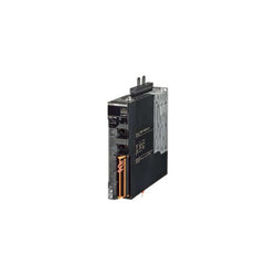
1S servo drive EtherCAT type 800 W 1~ 230 VAC
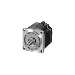
AC DC & Servo Motors 3000rpm INC K Mtr 1kW 480V

AC DC & Servo Motors 750W 480V 3000rpm ABS B K Mtr

AC DC & Servo Motors 3kW 480V 3000rpm INC K Mtr
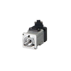
1S AC servo motor 750 W 230 VAC 3000 rpm 2.39 Nm absolute encoder with brake

PLC Direct is not an authorized distributor. We offer a broad range of in-stock products with minimal lead time.

BRAND NEW CONDITION, GUARANTEED.

BRAND NEW CONDITION, GUARANTEED.

BRAND NEW CONDITION, GUARANTEED.

The SGD7S-2R8AA0A stands out as a dedicated single-axis servo amplifier, engineered to deliver exceptional performance in 3-phase, 200V systems with an efficiency of 0.4W. It is designed with an EtherCAT interface to facilitate easy and effective communication within industrial automation setups, ensuring accurate single-axis motion control. Ideal for specialized servo drive and control tasks, its reliability and precision make it indispensable for enhancing operational efficiency and control in complex servo applications.
PLC Direct is not an authorized distributor. We offer a broad range of in-stock products with minimal lead time.

The SGD7S5R5A30A Sigma-7 servo amplifier delivers exceptional performance with a power output of 0.75 kW in a 200V, 1/3 phase setup. Its integration of MECHATROLINK III communication through an RJ45 connector enhances its suitability for automated applications, providing precise control and superior adaptability. Designed for durability and ease of connection, this amplifier is an ideal solution for contemporary industrial applications requiring reliable motion control.
Variable speed drive ATV71 - 2.2kW-3HP - 480V - EMC filter-w/o graphic terminal

Main
| Characteristic | Value(s) |
|---|---|
| Range of Product | Altivar 71 |
| Product or Component Type | Variable speed drive |
| Product Specific Application | Complex, high-power machines |
| Component name | ATV71 |
| Motor power kW | 4 kW, 3 phase 380...480 V |
| Maximum Horse Power Rating | 5 hp, 3 phase 380...480 V |
| Maximum motor cable length | 164.04 ft (50 m) shielded cable 328.08 ft (100 m) unshielded cable |
| power supply voltage | 380...480 V - 15...10 % |
| Phase | 3 phase |
| Line current | 11.5 A 480 V 3 phase 4 kW / 5 hp 14.1 A 380 V 3 phase 4 kW / 5 hp |
| EMC filter | Integrated |
| Assembly style | With heat sink |
| Variant | Without remote graphic terminal |
| Apparent power | 9.3 kVA 380 V 3 phase 4 kW / 5 hp |
| Prospective line Isc | 5 kA 3 phase |
| Nominal output current | 10.5 A 4 kHz 380 V 3 phase 4 kW / 5 hp 7.6 A 4 kHz 460 V 3 phase 4 kW / 5 hp |
| Maximum transient current | 15.8 A 60 s 3 phase 4 kW / 5 hp 17.3 A 2 s 3 phase 4 kW / 5 hp |
| Output frequency | 0.1â¦599 Hz |
| Nominal switching frequency | 4 kHz |
| Switching frequency | 1...16 kHz adjustable 4...16 kHz with derating factor |
| Asynchronous motor control profile | Voltage/frequency ratio (2 or 5 points) Sensorless flux vector control (SFVC) (voltage or current vector) ENA (Energy adaptation) system for unbalanced loads Flux vector control (FVC) with sensor (current vector) |
| Type of polarization | No impedance Modbus |
Complementary
| Characteristic | Value(s) |
|---|---|
| Product destination | Asynchronous motors Synchronous motors |
| power supply voltage limits | 323â¦528 V |
| power supply frequency | 50...60 Hz - 5...5 % |
| power supply frequency limits | 47.5...63 Hz |
| Speed range | 1â¦100 asynchronous motor in open-loop mode, without speed feedback 1â¦1000 asynchronous motor in closed-loop mode with encoder feedback 1â¦50 synchronous motor in open-loop mode, without speed feedback |
| Speed accuracy | +/- 0.01 % of nominal speed in closed-loop mode with encoder feedback 0.2 Tn to Tn +/- 10 % of nominal slip without speed feedback 0.2 Tn to Tn |
| Torque accuracy | +/- 15 % in open-loop mode, without speed feedback +/- 5 % in closed-loop mode with encoder feedback |
| Transient overtorque | 170 % +/- 10 % 60 s every 10 minutes 220 % +/- 10 % 2 s |
| Braking torque | <= 150 % with braking or hoist resistor 30 % without braking resistor |
| Synchronous motor control profile | Vector control without speed feedback |
| Regulation loop | Adjustable PI regulator |
| Motor slip compensation | Adjustable Suppressable Not available in voltage/frequency ratio (2 or 5 points) Automatic whatever the load |
| diagnostic | 1 LED (red) for drive voltage |
| Output voltage | <= power supply voltage |
| Insulation | Electrical between power and control |
| type of cable for mounting in an enclosure | With a NEMA Type1 kit 3 UL 508 cable 104 °F (40 °C), copper 75 °C / PVC With an IP21 or an IP31 kit 3 IEC cable 104 °F (40 °C), copper 70 °C / PVC Without mounting kit 1 IEC cable 113 °F (45 °C), copper 70 °C / PVC Without mounting kit 1 IEC cable 113 °F (45 °C), copper 90 °C / XLPE/EPR |
| Electrical connection | Terminal 2.5 mm², AWG 14 AI1-/AI1+, AI2, AO1, R1A, R1B, R1C, R2A, R2B, LI1...LI6, PWR) Terminal 4 mm², AWG 10 L1/R, L2/S, L3/T, U/T1, V/T2, W/T3, PC/-, PO, PA/+, PA, PB) |
| Tightening torque | 5.3 lbf.in (0.6 N.m) AI1-/AI1+, AI2, AO1, R1A, R1B, R1C, R2A, R2B, LI1...LI6, PWR) 12.4 lbf.in (1.4 N.m), 12.3 lb.in L1/R, L2/S, L3/T, U/T1, V/T2, W/T3, PC/-, PO, PA/+, PA, PB) |
| Supply | Internal supply for reference potentiometer (1 to 10 kOhm) 10.5 V DC +/- 5 %, <10 mA overload and short-circuit protection Internal supply 24 V DC 21â¦27 V), <200 mA overload and short-circuit protection |
| Analogue input number | 2 |
| Analogue input type | AI1-/Al1+ bipolar differential voltage +/- 10 V DC 24 V max 11 bits + sign AI2 software-configurable current 0...20 mA 242 Ohm 11 bits AI2 software-configurable voltage 0...10 V DC 24 V max 30000 Ohm 11 bits |
| input sampling time | 2 ms +/- 0.5 ms AI1-/Al1+) - analog 2 ms +/- 0.5 ms Al2) - analog 2 ms +/- 0.5 ms LI1...LI5) - discrete 2 ms +/- 0.5 ms LI6)if configured as logic input - discrete |
| Response time | <= 100 ms in STO (Safe Torque Off) AO1 2 ms +/- 0.5 ms analog R1A, R1B, R1C 7 ms +/- 0.5 ms discrete R2A, R2B 7 ms +/- 0.5 ms discrete |
| absolute accuracy precision | +/- 0.6 % AI1-/Al1+) for a temperature variation 60 °C +/- 0.6 % AI2) for a temperature variation 60 °C +/- 1 % AO1) for a temperature variation 60 °C |
| Linearity error | +/- 0.15 % of maximum value AI1-/Al1+, AI2) +/- 0.2 % AO1) |
| Analogue output number | 1 |
| Analogue output type | AO1 software-configurable logic output 10 V 20 mA AO1 software-configurable current 0...20 mA 500 Ohm 10 bits AO1 software-configurable voltage 0...10 V DC 470 Ohm 10 bits |
| Discrete output number | 2 |
| Discrete output type | Configurable relay logic R1A, R1B, R1C) NO/NC - 100000 cycles Configurable relay logic R2A, R2B) NO - 100000 cycles |
| Minimum switching current | 3 mA 24 V DC configurable relay logic |
| Maximum switching current | R1, R2 2 A 250 V AC inductive, cos phi = 0.4 R1, R2 2 A 30 V DC inductive, cos phi = 0.4 R1, R2 5 A 250 V AC resistive, cos phi = 1 R1, R2 5 A 30 V DC resistive, cos phi = 1 |
| Discrete input number | 7 |
| Discrete input type | LI1...LI5 programmable 24 V DC level 1 PLC 3500 Ohm LI6 switch-configurable 24 V DC level 1 PLC 3500 Ohm LI6 switch-configurable PTC probe 0â¦6 1500 Ohm PWR safety input 24 V DC 1500 Ohm ISO 13849-1 level d |
| Discrete input logic | Negative logic (sink) LI1...LI5), > 16 V, < 10 V Positive logic (source) LI1...LI5), < 5 V, > 11 V Negative logic (sink) LI6)if configured as logic input, > 16 V, < 10 V Positive logic (source) LI6)if configured as logic input, < 5 V, > 11 V |
| Acceleration and deceleration ramps | Linear adjustable separately from 0.01 to 9000 s S, U or customized Automatic adaptation of ramp if braking capacity exceeded, by using resistor |
| Braking to standstill | By DC injection |
| Protection type | Against exceeding limit speed drive Against input phase loss drive Break on the control circuit drive Input phase breaks drive Line supply overvoltage drive Line supply undervoltage drive Overcurrent between output phases and earth drive Overheating protection drive Overvoltages on the DC bus drive Short-circuit between motor phases drive Thermal protection drive Motor phase break motor Power removal motor Thermal protection motor |
| Insulation resistance | > 1 mOhm 500 V DC for 1 minute to earth |
| Frequency resolution | Analog input 0.024/50 Hz Display unit 0.1 Hz |
| Communication Port Protocol | CANopen Modbus |
| Connector type | 1 RJ45 on front face)Modbus 1 RJ45 on terminal)Modbus Male SUB-D 9 on RJ45CANopen |
| Physical interface | 2-wire RS 485 Modbus |
| Transmission frame | RTU Modbus |
| Transmission rate | 4800 bps, 9600 bps, 19200 bps, 38.4 Kbps Modbus on terminal 9600 bps, 19200 bps Modbus on front face 20 kbps, 50 kbps, 125 kbps, 250 kbps, 500 kbps, 1 Mbps CANopen |
| Data format | 8 bits, 1 stop, even parity Modbus on front face 8 bits, odd even or no configurable parity Modbus on terminal |
| Number of addresses | 1â¦127 CANopen 1â¦247 Modbus |
| Method of access | Slave CANopen |
| Marking | CE |
| Operating position | Vertical +/- 10 degree |
| Height | 10.2 in (260 mm) |
| Depth | 7.4 in (187 mm) |
| Width | 6.1 in (155 mm) |
| Product Weight | 8.8 lb(US) (4 kg) |
| Option card | Communication card CC-Link Controller inside programmable card Communication card DeviceNet Communication card EtherNet/IP Communication card Fipio I/O extension card Communication card Interbus-S Interface card for encoder Communication card Modbus Plus Communication card Modbus TCP Communication card Modbus/Uni-Telway Overhead crane card Communication card Profibus DP Communication card Profibus DP V1 |

Altivar Machine ATV320 range is an offer of variable speed drives designed for Original Equipment Manufacturers (OEMs). Its compact form factor allows vertical stacking of drives inside machine frames. It works at a rated power up to 1.5kW / 2hp and a rated voltage from 200V to 240V AC. Its robust design with IEC 60721-3-3 class 3C3 coated printed circuit boards allows to extend machine availability in harsh environmental conditions, for example at ambient temperatures of up to 60°C without the need of additional cooling. It incorporates functions suitable for the most common applications, including torque and speed accuracy at very low speed, high dynamic performance with flux vector control without sensor and extended frequency range for high-speed motors. It also incorporates parallel connection of motors and special drives using the voltage/frequency ratio and static speed accuracy and energy saving for open-loop synchronous motors. It weighs 1.4kg and its dimensions are 105mm wide, 143mm high, 138mm deep. The drive software includes 5 safety functions that help machines meet safety requirements, whether or not they are used in conjunction with a Preventa safety module. These safety functions are configured using SoMove software. Altivar Machine ATV320 was designed for Original Equipment Manufacturers (OEMs) that meets simple and advanced application requirements covered for packaging, material handling, textile, material working, mechanical actuators and hoisting. It conforms to IEC, UL, TUV, KC and other international standards. Mounting accessories and external options (braking resistors, line chokes, motor chokes, additional EMC filters) are available with Altivar Machine ATV320 drives. The type of external accessories and options depends on the drive rating. The product is delivered in one package. It is designed to be mounted in vertical position (+/- 10 °) on a panel, thanks to 4 fixing holes. It is fully integrated inside Schneider Electricâs EcoStruxure Machine through DTM. It is possible to configure, control, and diagnose ATV320 drives directly in SoMachine and SoMove software by means of the same software brick (DTM).
Main
| Characteristic | Value(s) |
|---|---|
| Range of Product | Altivar Machine ATV320 |
| Product or Component Type | Variable speed drive |
| Product Specific Application | Complex machines |
| Variant | Standard version Standard version |
| Format of the drive | Compact |
| Mounting Mode | Wall mount |
| Communication Port Protocol | Modbus serial CANopen |
| Option card | communication module, CANopen communication module, EtherCAT communication module, Profibus DP V1 communication module, PROFINET communication module, Ethernet Powerlink communication module, EtherNet/IP communication module, DeviceNet |
| [Us] rated supply voltage | 200...240 V - 15...10 % |
| nominal output current | 8.0 A |
| Motor power kW | 1.5 kW heavy duty |
| EMC filter | Without EMC filter |
| IP degree of protection | IP20 |
Complementary
| Characteristic | Value(s) |
|---|---|
| Discrete input number | 7 |
| Discrete input type | STO safe torque off, 24 V DC1.5 kOhm DI1...DI6 logic inputs, 24 V DC 30 V) DI5 programmable as pulse input 0â¦30 kHz, 24 V DC 30 V) |
| Discrete input logic | Positive logic (source) Negative logic (sink) |
| Discrete output number | 3 |
| Discrete output type | Open collector DQ+ 0â¦1 kHz 30 V DC 100 mA Open collector DQ- 0â¦1 kHz 30 V DC 100 mA |
| Analogue input number | 3 |
| Analogue input type | AI1 voltage 0...10 V DC 30 kOhm 10 bits AI2 bipolar differential voltage +/- 10 V DC 30 kOhm 10 bits AI3 current 0...20 mA (or 4-20 mA, x-20 mA, 20-x mA or other patterns by configuration) 250 Ohm 10 bits |
| Analogue output number | 1 |
| Analogue output type | Software-configurable current AQ1 0...20 mA 800 Ohm 10 bits Software-configurable voltage AQ1 0...10 V DC 470 Ohm 10 bits |
| Relay output type | Configurable relay logic R1A 1 NO 100000 cycles Configurable relay logic R1B 1 NC 100000 cycles Configurable relay logic R1C Configurable relay logic R2A 1 NO 100000 cycles Configurable relay logic R2C |
| Maximum switching current | Relay output R1A, R1B, R1C resistive, cos phi = 1 3 A 250 V AC Relay output R1A, R1B, R1C resistive, cos phi = 1 3 A 30 V DC Relay output R1A, R1B, R1C, R2A, R2C inductive, cos phi = 0.4 7 ms 2 A 250 V AC Relay output R1A, R1B, R1C, R2A, R2C inductive, cos phi = 0.4 7 ms 2 A 30 V DC Relay output R2A, R2C resistive, cos phi = 1 5 A 250 V AC Relay output R2A, R2C resistive, cos phi = 1 5 A 30 V DC |
| Minimum switching current | Relay output R1A, R1B, R1C, R2A, R2C 5 mA 24 V DC |
| Method of access | Slave CANopen |
| 4 quadrant operation possible | True |
| Asynchronous motor control profile | Voltage/frequency ratio, 5 points Flux vector control without sensor, standard Voltage/frequency ratio - Energy Saving, quadratic U/f Flux vector control without sensor - Energy Saving Voltage/frequency ratio, 2 points |
| Synchronous motor control profile | Vector control without sensor |
| Maximum output frequency | 0.599 kHz |
| Acceleration and deceleration ramps | Linear U S CUS Ramp switching Acceleration/deceleration ramp adaptation Acceleration/deceleration automatic stop with DC injection |
| Motor slip compensation | Automatic whatever the load Adjustable 0...300 % Not available in voltage/frequency ratio (2 or 5 points) |
| Switching frequency | 2...16 kHz adjustable 4...16 kHz with derating factor |
| Nominal switching frequency | 4 kHz |
| Braking to standstill | By DC injection |
| Brake chopper integrated | True |
| Line current | 11.1 A 200 V heavy duty) 9.3 A 240 V heavy duty) |
| Maximum Input Current per Phase | 11.1 A |
| Maximum output voltage | 240 V |
| Apparent power | 3.9 kVA 240 V heavy duty) |
| Network Frequency | 50-60 Hz |
| Relative symmetric network frequency tolerance | 5 % |
| Prospective line Isc | 5 kA |
| Base load current at high overload | 4 A |
| Power dissipation in W | Fan 72.0 W 200 V 4 kHz |
| With safety function Safely Limited Speed (SLS) | True |
| With safety function Safe brake management (SBC/SBT) | False |
| With safety function Safe Operating Stop (SOS) | False |
| With safety function Safe Position (SP) | False |
| With safety function Safe programmable logic | False |
| With safety function Safe Speed Monitor (SSM) | False |
| With safety function Safe Stop 1 (SS1) | True |
| With sft fct Safe Stop 2 (SS2) | False |
| With safety function Safe torque off (STO) | True |
| With safety function Safely Limited Position (SLP) | False |
| With safety function Safe Direction (SDI) | False |
| Protection type | Input phase breaks drive Overcurrent between output phases and earth drive Overheating protection drive Short-circuit between motor phases drive Thermal protection drive |
| Width | 4.1 in (105.0 mm) |
| Height | 5.6 in (143.0 mm) |
| Depth | 5.4 in (138.0 mm) |
| Product Weight | 3.09 lb(US) (1.4 kg) |
| Transient overtorque | 170â¦200 % of nominal motor torque |