
 1 year warranty


BRAND NEW CONDITION, GUARANTEED.
PLC Direct is not an authorized distributor. We offer a broad range of in-stock products with minimal lead time.
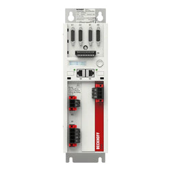
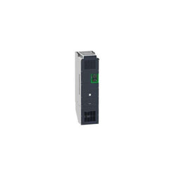
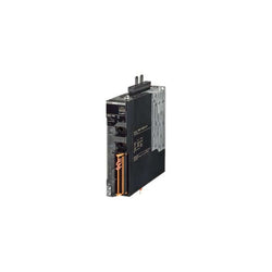
Digital Compact Servo Drive, 2-axis module, 100…480 V AC, rated output current 2 x 6 A, EtherCAT interface, OCT, hardware version 2.0, firmware version ? 2.10 (1)

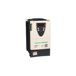
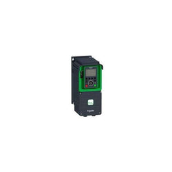
Variable Speed Drive - ATV930 - 3kW - 400/480V - with braking unit - IP21

Variable Speed Drive ATV630 - 2.2kW/3hp - 380...480V - IP21/UL type 1
Main
| Characteristic | Value(s) |
|---|---|
| Range of Product | Altivar |
| Product or Component Type | Variable speed drive |
| Product Specific Application | Simple machine |
| Component name | ATV31 |
| Assembly style | With heat sink |
| Variant | With drive order potentiometer |
| EMC filter | Integrated |
| [Us] rated supply voltage | 380...500 V - 5...5 % |
| Supply frequency | 50...60 Hz - 5...5 % |
| Phase | 3 phase |
| Motor power kW | 0.37 kW 4 kHz |
| Maximum Horse Power Rating | 0.5 hp 4 kHz |
| Line current | 1.7 A 500 V 2.2 A 380 V, Isc = 1 kA |
| Apparent power | 1.5 kVA |
| Prospective line Isc | 1 kA |
| Nominal output current | 1.5 A 4 kHz |
| Maximum transient current | 2.3 A 60 s |
| Power dissipation in W | 32 W at nominal load |
| Asynchronous motor control profile | Factory set : constant torque Sensorless flux vector control with PWM type motor control signal |
| Analogue input number | 4 |
Complementary
| Characteristic | Value(s) |
|---|---|
| Product destination | Asynchronous motors |
| Supply voltage limits | 323â¦550 V |
| Network Frequency | 47.5...63 Hz |
| Output frequency | 0.0005â¦0.5 kHz |
| Nominal switching frequency | 4 kHz |
| Switching frequency | 2...16 kHz adjustable |
| Speed range | 1â¦50 |
| Transient overtorque | 150â¦170 % of nominal motor torque |
| Braking torque | <= 150 % 60 s with braking resistor 100 % with braking resistor continuously 150 % without braking resistor |
| Regulation loop | Frequency PI regulator |
| Motor slip compensation | Adjustable Suppressable Automatic whatever the load |
| Output voltage | <= power supply voltage |
| Electrical connection | Al1, Al2, Al3, AOV, AOC, R1A, R1B, R1C, R2A, R2B, LI1...LI6 terminal 0.004 in² (2.5 mm²) AWG 14 L1, L2, L3, U, V, W, PA, PB, PA/+, PC/- terminal 0.004 in² (2.5 mm²) AWG 14 |
| Tightening torque | Al1, Al2, Al3, AOV, AOC, R1A, R1B, R1C, R2A, R2B, LI1...LI6 5.3 lbf.in (0.6 N.m) L1, L2, L3, U, V, W, PA, PB, PA/+, PC/- 7.08 lbf.in (0.8 N.m) |
| Insulation | Electrical between power and control |
| Supply | Internal supply for logic inputs 19...30 V 100 mA overload and short-circuit protection Internal supply for reference potentiometer (2.2 to 10 kOhm) 10...10.8 V 10 mA overload and short-circuit protection |
| Analogue input type | AI3 configurable current 0...20 mA 250 Ohm AI1 configurable voltage 0...10 V 30 V max 30000 Ohm AI2 configurable voltage +/- 10 V 30 V max 30000 Ohm AIP potentiometer reference 8 ms 10 bits +/- 4.3 % +/- 0.2 % |
| Sampling duration | LI1...LI6 4 ms discrete AI1, AI2, AI3 8 ms analog |
| Response time | AOV, AOC 8 ms analog R1A, R1B, R1C, R2A, R2B 8 ms discrete |
| Linearity error | +/- 0.2 % output |
| Analogue output number | 2 |
| Analogue output type | AOC configurable current 0...20 mA 800 Ohm 8 bits AOV configurable voltage 0...10 V 470 Ohm 8 bits |
| Discrete input logic | Positive logic (source) LI1...LI6), < 5 V, > 11 V Logic input not wired LI1...LI4), < 13 V Negative logic (source) LI1...LI6), > 19 V |
| Discrete output number | 2 |
| Discrete output type | Configurable relay logic R1A, R1B, R1C) 1 NO + 1 NC - 100000 cycles Configurable relay logic R2A, R2B) NC - 100000 cycles |
| Minimum switching current | R1-R2 10 mA 5 V DC |
| Maximum switching current | R1-R2 2 A 250 V AC inductive, cos phi = 0.4 7 ms R1-R2 2 A 30 V DC inductive, cos phi = 0.4 7 ms R1-R2 5 A 250 V AC resistive, cos phi = 1 0 ms R1-R2 5 A 30 V DC resistive, cos phi = 1 0 ms |
| Discrete input number | 6 |
| Discrete input type | LI1...LI6) programmable 24 V, 0â¦100 mA PLC 3500 Ohm |
| Acceleration and deceleration ramps | S, U or customized Linear adjustable separately from 0.1 to 999.9 s |
| Braking to standstill | By DC injection |
| Protection type | Input phase breaks drive Line supply overvoltage and undervoltage safety circuits drive Line supply phase loss safety function, for three phases supply drive Motor phase breaks drive Overcurrent between output phases and earth (on power up only) drive Overheating protection drive Short-circuit between motor phases drive Thermal protection motor |
| Insulation resistance | >= 500 mOhm 500 V DC for 1 minute |
| Display type | 1 LED Red)drive voltage Four 7-segment display unitsCANopen bus status |
| Time constant | 5 ms for reference change |
| Frequency resolution | Display unit 0.1 Hz Analog input 0.1...100 Hz |
| Connector type | 1 RJ45 CANopen via VW3 CANTAP2 adaptor 1 RJ45 Modbus |
| Physical interface | RS485 multidrop serial link CANopen via VW3 CANTAP2 adaptor RS485 multidrop serial link Modbus |
| Transmission frame | RTU CANopen via VW3 CANTAP2 adaptor RTU Modbus |
| Transmission Rate | 10, 20, 50, 125, 250, 500 kbps or 1 Mbps CANopen via VW3 CANTAP2 adaptor 4800, 9600 or 19200 bps Modbus |
| Number of addresses | 1â¦127 CANopen via VW3 CANTAP2 adaptor 1â¦247 Modbus |
| Number of drive | 127 CANopen via VW3 CANTAP2 adaptor 31 Modbus |
| Marking | CE |
| Operating position | Vertical +/- 10 degree |
| Product Weight | 4.0 lb(US) (1.8 kg) |
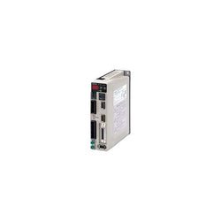
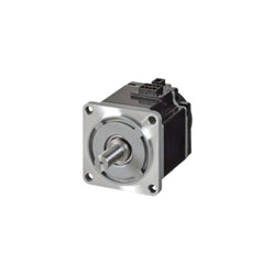
Motor Drives 400W 200V 1PHA GSERIES SRV DR

BRAND NEW CONDITION, GUARANTEED.
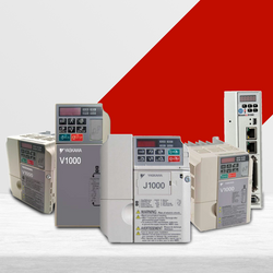
The SGD7S120A20A is a single-axis amplifier engineered for optimal performance in demanding industrial settings. Offering a speed frequency response of 3.1 kHz and delivering 1.5 kW of power at 200V, this amplifier is well-suited for precise motion control applications. Its design supports effective integration into sophisticated automation systems, providing the responsiveness and reliability essential for dynamic operational demands.

PLC Direct is not an authorized distributor. We offer a broad range of in-stock products with minimal lead time.

Main
| Characteristic | Value(s) |
|---|---|
| Range of Product | Altivar 71 |
| Product or Component Type | Variable speed drive |
| Product Specific Application | Complex, high-power machines |
| Component name | ATV71 |
| Motor power kW | 1.5 kW, 3 phase 380...480 V |
| Maximum Horse Power Rating | 2 hp, 3 phase 380...480 V |
| Maximum motor cable length | 164.04 ft (50 m) shielded cable 328.08 ft (100 m) unshielded cable |
| power supply voltage | 380...480 V - 15...10 % |
| Phase | 3 phase |
| Line current | 5.3 A 480 V 3 phase 1.5 kW / 2 hp 5.8 A 380 V 3 phase 1.5 kW / 2 hp |
| EMC filter | Integrated |
| Assembly style | With heat sink |
| Variant | Without remote graphic terminal |
| Apparent power | 3.8 kVA 380 V 3 phase 1.5 kW / 2 hp |
| Prospective line Isc | 5 kA 3 phase |
| Nominal output current | 3.4 A 4 kHz 460 V 3 phase 1.5 kW / 2 hp 4.1 A 4 kHz 380 V 3 phase 1.5 kW / 2 hp |
| Maximum transient current | 6.2 A 60 s 3 phase 1.5 kW / 2 hp 6.8 A 2 s 3 phase 1.5 kW / 2 hp |
| Output frequency | 0.1â¦599 Hz |
| Nominal switching frequency | 4 kHz |
| Switching frequency | 1...16 kHz adjustable 4...16 kHz with derating factor |
| Asynchronous motor control profile | Voltage/frequency ratio (2 or 5 points) Sensorless flux vector control (SFVC) (voltage or current vector) ENA (Energy adaptation) system for unbalanced loads Flux vector control (FVC) with sensor (current vector) |
| Type of polarization | No impedance Modbus |
Complementary
| Characteristic | Value(s) |
|---|---|
| Product destination | Asynchronous motors Synchronous motors |
| power supply voltage limits | 323â¦528 V |
| power supply frequency | 50...60 Hz - 5...5 % |
| power supply frequency limits | 47.5...63 Hz |
| Speed range | 1â¦100 asynchronous motor in open-loop mode, without speed feedback 1â¦1000 asynchronous motor in closed-loop mode with encoder feedback 1â¦50 synchronous motor in open-loop mode, without speed feedback |
| Speed accuracy | +/- 0.01 % of nominal speed in closed-loop mode with encoder feedback 0.2 Tn to Tn +/- 10 % of nominal slip without speed feedback 0.2 Tn to Tn |
| Torque accuracy | +/- 15 % in open-loop mode, without speed feedback +/- 5 % in closed-loop mode with encoder feedback |
| Transient overtorque | 170 % +/- 10 % 60 s every 10 minutes 220 % +/- 10 % 2 s |
| Braking torque | <= 150 % with braking or hoist resistor 30 % without braking resistor |
| Synchronous motor control profile | Vector control without speed feedback |
| Regulation loop | Adjustable PI regulator |
| Motor slip compensation | Adjustable Automatic whatever the load Suppressable Not available in voltage/frequency ratio (2 or 5 points) |
| diagnostic | 1 LED (red) for drive voltage |
| Output voltage | <= power supply voltage |
| Insulation | Electrical between power and control |
| type of cable for mounting in an enclosure | With a NEMA Type1 kit 3 UL 508 cable 104 °F (40 °C), copper 75 °C / PVC With an IP21 or an IP31 kit 3 IEC cable 104 °F (40 °C), copper 70 °C / PVC Without mounting kit 1 IEC cable 113 °F (45 °C), copper 70 °C / PVC Without mounting kit 1 IEC cable 113 °F (45 °C), copper 90 °C / XLPE/EPR |
| Electrical connection | Terminal 2.5 mm², AWG 14 AI1-/AI1+, AI2, AO1, R1A, R1B, R1C, R2A, R2B, LI1...LI6, PWR) Terminal 4 mm², AWG 10 L1/R, L2/S, L3/T, U/T1, V/T2, W/T3, PC/-, PO, PA/+, PA, PB) |
| Tightening torque | 5.3 lbf.in (0.6 N.m) AI1-/AI1+, AI2, AO1, R1A, R1B, R1C, R2A, R2B, LI1...LI6, PWR) 12.4 lbf.in (1.4 N.m), 12.3 lb.in L1/R, L2/S, L3/T, U/T1, V/T2, W/T3, PC/-, PO, PA/+, PA, PB) |
| Supply | Internal supply for reference potentiometer (1 to 10 kOhm) 10.5 V DC +/- 5 %, <10 mA overload and short-circuit protection Internal supply 24 V DC 21â¦27 V), <200 mA overload and short-circuit protection |
| Analogue input number | 2 |
| Analogue input type | AI1-/Al1+ bipolar differential voltage +/- 10 V DC 24 V max 11 bits + sign AI2 software-configurable current 0...20 mA 242 Ohm 11 bits AI2 software-configurable voltage 0...10 V DC 24 V max 30000 Ohm 11 bits |
| input sampling time | 2 ms +/- 0.5 ms AI1-/Al1+) - analog 2 ms +/- 0.5 ms Al2) - analog 2 ms +/- 0.5 ms LI1...LI5) - discrete 2 ms +/- 0.5 ms LI6)if configured as logic input - discrete |
| Response time | <= 100 ms in STO (Safe Torque Off) AO1 2 ms +/- 0.5 ms analog R1A, R1B, R1C 7 ms +/- 0.5 ms discrete R2A, R2B 7 ms +/- 0.5 ms discrete |
| absolute accuracy precision | +/- 0.6 % AI1-/Al1+) for a temperature variation 60 °C +/- 0.6 % AI2) for a temperature variation 60 °C +/- 1 % AO1) for a temperature variation 60 °C |
| Linearity error | +/- 0.15 % of maximum value AI1-/Al1+, AI2) +/- 0.2 % AO1) |
| Analogue output number | 1 |
| Analogue output type | AO1 software-configurable logic output 10 V 20 mA AO1 software-configurable current 0...20 mA 500 Ohm 10 bits AO1 software-configurable voltage 0...10 V DC 470 Ohm 10 bits |
| Discrete output number | 2 |
| Discrete output type | Configurable relay logic R1A, R1B, R1C) NO/NC - 100000 cycles Configurable relay logic R2A, R2B) NO - 100000 cycles |
| Minimum switching current | 3 mA 24 V DC configurable relay logic |
| Maximum switching current | R1, R2 2 A 250 V AC inductive, cos phi = 0.4 R1, R2 2 A 30 V DC inductive, cos phi = 0.4 R1, R2 5 A 250 V AC resistive, cos phi = 1 R1, R2 5 A 30 V DC resistive, cos phi = 1 |
| Discrete input number | 7 |
| Discrete input type | LI1...LI5 programmable 24 V DC level 1 PLC 3500 Ohm LI6 switch-configurable 24 V DC level 1 PLC 3500 Ohm LI6 switch-configurable PTC probe 0â¦6 1500 Ohm PWR safety input 24 V DC 1500 Ohm ISO 13849-1 level d |
| Discrete input logic | Negative logic (sink) LI1...LI5), > 16 V, < 10 V Positive logic (source) LI1...LI5), < 5 V, > 11 V Negative logic (sink) LI6)if configured as logic input, > 16 V, < 10 V Positive logic (source) LI6)if configured as logic input, < 5 V, > 11 V |
| Acceleration and deceleration ramps | S, U or customized Automatic adaptation of ramp if braking capacity exceeded, by using resistor Linear adjustable separately from 0.01 to 9000 s |
| Braking to standstill | By DC injection |
| Protection type | Against exceeding limit speed drive Against input phase loss drive Break on the control circuit drive Input phase breaks drive Line supply overvoltage drive Line supply undervoltage drive Overcurrent between output phases and earth drive Overheating protection drive Overvoltages on the DC bus drive Short-circuit between motor phases drive Thermal protection drive Motor phase break motor Power removal motor Thermal protection motor |
| Insulation resistance | > 1 mOhm 500 V DC for 1 minute to earth |
| Frequency resolution | Analog input 0.024/50 Hz Display unit 0.1 Hz |
| Communication Port Protocol | CANopen Modbus |
| Connector type | 1 RJ45 on front face)Modbus 1 RJ45 on terminal)Modbus Male SUB-D 9 on RJ45CANopen |
| Physical interface | 2-wire RS 485 Modbus |
| Transmission frame | RTU Modbus |
| Transmission rate | 4800 bps, 9600 bps, 19200 bps, 38.4 Kbps Modbus on terminal 9600 bps, 19200 bps Modbus on front face 20 kbps, 50 kbps, 125 kbps, 250 kbps, 500 kbps, 1 Mbps CANopen |
| Data format | 8 bits, 1 stop, even parity Modbus on front face 8 bits, odd even or no configurable parity Modbus on terminal |
| Number of addresses | 1â¦127 CANopen 1â¦247 Modbus |
| Method of access | Slave CANopen |
| Marking | CE |
| Operating position | Vertical +/- 10 degree |
| Height | 9.06 in (230 mm) |
| Depth | 6.9 in (175 mm) |
| Width | 5.1 in (130 mm) |
| Product Weight | 6.6 lb(US) (3 kg) |
| Option card | Communication card CC-Link Controller inside programmable card Communication card DeviceNet Communication card EtherNet/IP Communication card Fipio I/O extension card Communication card Interbus-S Interface card for encoder Communication card Modbus Plus Communication card Modbus TCP Communication card Modbus/Uni-Telway Overhead crane card Communication card Profibus DP Communication card Profibus DP V1 |
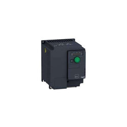
This Altivar 320 variable speed drive can feed 3-phase synchronous and asynchronous motors. Its compact form factor allows vertical stacking of drives inside machine frames. It works at a rated power up to 3kW / 4hp and a rated voltage from 380V to 500V AC. Its robust design with IEC 60721-3-3 class 3C3 coated printed circuit boards allows to extend machine availability in harsh environmental conditions, for example at ambient temperatures of up to 60°C without the need of additional cooling. It incorporates functions suitable for the most common applications, including torque and speed accuracy at very low speed, high dynamic performance with flux vector control without sensor and extended frequency range for high-speed motors. It also incorporates parallel connection of motors and special drives using the voltage/frequency ratio and static speed accuracy and energy saving for open-loop synchronous motors. The drive software includes 5 safety functions that help machines meet safety requirements, whether or not they are used in conjunction with a Preventa safety module. These safety functions are configured using SoMove software. Altivar Machine ATV320 was designed for Original Equipment Manufacturers (OEMs) that meets simple and advanced application requirements covered for packaging, material handling, textile, material working, mechanical actuators and hoisting. It conforms to international standards IEC/EN 61800-5-1 and IEC/EN 61800-3 (immunity and conducted and radiated EMC emissions). It is also CE, UL, CSA, NOM, EAC and RCM certified. Mounting accessories and external options (braking resistors, line chokes, motor chokes, additional EMC filters) are available with Altivar Machine ATV320 drives. The type of external accessories and options depends on the drive rating. It is designed to be mounted in vertical position (+/- 10 °) on a panel, thanks to 4 fixing holes. It is fully integrated inside Schneider Electricâs EcoStruxure Machine through DTM. It is possible to configure, control, and diagnose ATV320 drives directly in SoMachine and SoMove software by means of the same software brick (DTM).
Main
| Characteristic | Value(s) |
|---|---|
| Range of Product | Altivar Machine ATV320 |
| Product or Component Type | Variable speed drive |
| Product Specific Application | Complex machines |
| Variant | Standard version |
| Format of the drive | Compact |
| Mounting Mode | Wall mount |
| Communication Port Protocol | Modbus serial CANopen |
| Option card | communication module, CANopen communication module, EtherCAT communication module, Profibus DP V1 communication module, PROFINET communication module, Ethernet Powerlink communication module, EtherNet/IP communication module, DeviceNet |
| [Us] rated supply voltage | 380...500 V - 15...10 % |
| nominal output current | 7.1 A |
| Motor power kW | 3.0 kW heavy duty |
| EMC filter | Class C2 EMC filter integrated |
| IP degree of protection | IP20 |
Complementary
| Characteristic | Value(s) |
|---|---|
| Discrete input number | 7 |
| Discrete input type | STO safe torque off, 24 V DC1.5 kOhm DI1...DI6 logic inputs, 24 V DC 30 V) DI5 programmable as pulse input 0â¦30 kHz, 24 V DC 30 V) |
| Discrete input logic | Positive logic (source) Negative logic (sink) |
| Discrete output number | 3 |
| Discrete output type | Open collector DQ+ 0â¦1 kHz 30 V DC 100 mA Open collector DQ- 0â¦1 kHz 30 V DC 100 mA |
| Analogue input number | 3 |
| Analogue input type | AI1 voltage 0...10 V DC 30 kOhm 10 bits AI2 bipolar differential voltage +/- 10 V DC 30 kOhm 10 bits AI3 current 0...20 mA (or 4-20 mA, x-20 mA, 20-x mA or other patterns by configuration) 250 Ohm 10 bits |
| Analogue output number | 1 |
| Analogue output type | Software-configurable current AQ1 0...20 mA 800 Ohm 10 bits Software-configurable voltage AQ1 0...10 V DC 470 Ohm 10 bits |
| Relay output type | Configurable relay logic R1A 1 NO 100000 cycles Configurable relay logic R1B 1 NC 100000 cycles Configurable relay logic R1C Configurable relay logic R2A 1 NO 100000 cycles Configurable relay logic R2C |
| Maximum switching current | Relay output R1A, R1B, R1C resistive, cos phi = 1 3 A 250 V AC Relay output R1A, R1B, R1C resistive, cos phi = 1 3 A 30 V DC Relay output R1A, R1B, R1C, R2A, R2C inductive, cos phi = 0.4 7 ms 2 A 250 V AC Relay output R1A, R1B, R1C, R2A, R2C inductive, cos phi = 0.4 7 ms 2 A 30 V DC Relay output R2A, R2C resistive, cos phi = 1 5 A 250 V AC Relay output R2A, R2C resistive, cos phi = 1 5 A 30 V DC |
| Minimum switching current | Relay output R1A, R1B, R1C, R2A, R2C 5 mA 24 V DC |
| Method of access | Slave CANopen |
| 4 quadrant operation possible | True |
| Asynchronous motor control profile | Voltage/frequency ratio, 5 points Flux vector control without sensor, standard Voltage/frequency ratio - Energy Saving, quadratic U/f Flux vector control without sensor - Energy Saving Voltage/frequency ratio, 2 points |
| Synchronous motor control profile | Vector control without sensor |
| Maximum output frequency | 0.599 kHz |
| Acceleration and deceleration ramps | Linear U S CUS Ramp switching Acceleration/deceleration ramp adaptation Acceleration/deceleration automatic stop with DC injection |
| Motor slip compensation | Automatic whatever the load Adjustable 0...300 % Not available in voltage/frequency ratio (2 or 5 points) |
| Switching frequency | 2...16 kHz adjustable 4...16 kHz with derating factor |
| Nominal switching frequency | 4 kHz |
| Braking to standstill | By DC injection |
| Brake chopper integrated | True |
| Line current | 11.1 A 380 V heavy duty) 8.4 A 500 V heavy duty) |
| Maximum Input Current per Phase | 11.1 A |
| Maximum output voltage | 500 V |
| Apparent power | 7.3 kVA 500 V heavy duty) |
| Network Frequency | 50-60 Hz |
| Relative symmetric network frequency tolerance | 5 % |
| Prospective line Isc | 5 kA |
| Base load current at high overload | 7.1 A |
| Power dissipation in W | Fan 93.0 W 380 V 4 kHz |
| With safety function Safely Limited Speed (SLS) | True |
| With safety function Safe brake management (SBC/SBT) | False |
| With safety function Safe Operating Stop (SOS) | False |
| With safety function Safe Position (SP) | False |
| With safety function Safe programmable logic | False |
| With safety function Safe Speed Monitor (SSM) | False |
| With safety function Safe Stop 1 (SS1) | True |
| With sft fct Safe Stop 2 (SS2) | False |
| With safety function Safe torque off (STO) | True |
| With safety function Safely Limited Position (SLP) | False |
| With safety function Safe Direction (SDI) | False |
| Protection type | Input phase breaks drive Overcurrent between output phases and earth drive Overheating protection drive Short-circuit between motor phases drive Thermal protection drive |
| Width | 5.5 in (140 mm) |
| Height | 7.2 in (184.0 mm) |
| Depth | 6.2 in (158.0 mm) |
| Product Weight | 4.6 lb(US) (2.1 kg) |
| Transient overtorque | 170â¦200 % of nominal motor torque |
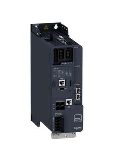
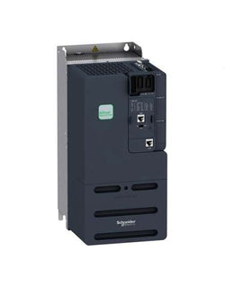
Variable Speed Drive - 1.5kW- 400V - 3 Phases - Altivar ATV340 Ethernet
Variable Speed Drive - ATV930 - 160kW - 400/480V - whitout braking unit - IP00
Main
| Characteristic | Value(s) |
|---|---|
| Range of Product | Altivar 61 |
| Product or Component Type | Variable speed drive |
| Product Specific Application | Pumping and ventilation machine |
| Component name | ATV61 |
| Motor power kW | 0.75 kW, single phase 200...240 V 1.5 kW, 3 phase 200...240 V |
| Maximum Horse Power Rating | 1 hp, single phase 200...240 V 2 hp, 3 phase 200...240 V |
| power supply voltage | 200...240 V - 15...10 % |
| supply number of phases | Single phase 3 phase |
| Line current | 11.3 A 200 V 3 phase 1.5 kW / 2 hp 12 A 200 V single phase 0.75 kW / 1 hp 9.6 A 240 V 3 phase 1.5 kW / 2 hp 9.9 A 240 V single phase 0.75 kW / 1 hp |
| EMC filter | Class C2 EMC filter integrated |
| Assembly style | With heat sink |
| Apparent power | 2.4 kVA 240 V single phase 0.75 kW / 1 hp 4 kVA 240 V 3 phase 1.5 kW / 2 hp |
| maximum prospective line Isc | 5 kA 3 phase 5 kA single phase |
| Maximum transient current | 5.7 A 60 s, single phase 9.6 A 60 s, 3 phase |
| Nominal switching frequency | 12 kHz |
| Switching frequency | 1...16 kHz adjustable 12...16 kHz with derating factor |
| asynchronous motor control | Voltage/frequency ratio, 2 points Flux vector control without sensor, standard Voltage/frequency ratio - Energy Saving, quadratic U/f Voltage/frequency ratio, 5 points |
| Synchronous motor control profile | Vector control without sensor, standard |
| Communication Port Protocol | Modbus CANopen |
| Type of polarization | No impedance Modbus |
| Option card | Communication card APOGEE FLN Communication card BACnet Communication card CC-Link Controller inside programmable card Communication card DeviceNet Communication card EtherNet/IP Communication card Fipio I/O extension card Communication card Interbus-S Communication card LonWorks Communication card METASYS N2 Communication card Modbus Plus Communication card Modbus TCP Communication card Modbus/Uni-Telway Multi-pump card Communication card Profibus DP Communication card Profibus DP V1 |
Complementary
| Characteristic | Value(s) |
|---|---|
| Product destination | Asynchronous motors Synchronous motors |
| power supply voltage limits | 170â¦264 V |
| power supply frequency | 50...60 Hz - 5...5 % |
| power supply frequency limits | 47.5...63 Hz |
| Continuous output current | 8 A 12 kHz, 230 V - 3 phase 4.8 A 12 kHz, 230 V - single phase |
| Output frequency | 0.1â¦599 Hz |
| Speed range | 1â¦100 in open-loop mode, without speed feedback |
| Speed accuracy | +/- 10 % of nominal slip 0.2 Tn to Tn without speed feedback |
| Torque accuracy | +/- 15 % in open-loop mode, without speed feedback |
| Transient overtorque | 130 % of nominal motor torque +/- 10 % 60 s |
| Braking torque | <= 125 % with braking resistor 30 % without braking resistor |
| Regulation loop | Frequency PI regulator |
| Motor slip compensation | Automatic whatever the load Not available in voltage/frequency ratio (2 or 5 points) Can be suppressed Adjustable |
| diagnostic | 1 LED (red) for drive voltage |
| Output voltage | <= power supply voltage |
| electrical isolation | Between power and control terminals |
| type of cable for mounting in an enclosure | With an IP21 or an IP31 kit 3 IEC cable 104 °F (40 °C), copper 70 °C / PVC With UL Type 1 kit 3 UL 508 cable 104 °F (40 °C), copper 75 °C / PVC Without mounting kit 1 IEC cable 113 °F (45 °C), copper 70 °C / PVC Without mounting kit 1 IEC cable 113 °F (45 °C), copper 90 °C / XLPE/EPR |
| Electrical connection | Terminal 2.5 mm² / AWG 14 AI1-/AI1+, AI2, AO1, R1A, R1B, R1C, R2A, R2B, LI1...LI6, PWR) Terminal 6 mm² / AWG 8 L1/R, L2/S, L3/T, U/T1, V/T2, W/T3, PC/-, PO, PA/+, PA, PB) |
| Tightening torque | 5.3 lbf.in (0.6 N.m) AI1-/AI1+, AI2, AO1, R1A, R1B, R1C, R2A, R2B, LI1...LI6, PWR) 12.4 lbf.in (1.4 N.m), 12.3 lb.in L1/R, L2/S, L3/T, U/T1, V/T2, W/T3, PC/-, PO, PA/+, PA, PB) |
| Supply | Internal supply for reference potentiometer (1 to 10 kOhm) 10.5 V DC, +/- 5 %, <10 mA overload and short-circuit protection Internal supply 24 V DC 21â¦27 V), <200 mA overload and short-circuit protection External supply 24 V DC 19â¦30 V) |
| Analogue input number | 2 |
| Analogue input type | AI1-/Al1+ bipolar differential voltage +/- 10 V DC 24 V max 11 bits + sign AI2 software-configurable current 0...20 mA 242 Ohm 11 bits AI2 software-configurable voltage 0...10 V DC 24 V max 30000 Ohm 11 bits |
| sampling time | 2 ms +/- 0.5 ms AI1-/Al1+) - analog input 2 ms +/- 0.5 ms Al2) - analog input 2 ms +/- 0.5 ms AO1) - analog output 2 ms +/- 0.5 ms LI1...LI5) - discrete input 2 ms +/- 0.5 ms LI6)if configured as logic input - discrete input |
| absolute accuracy precision | +/- 0.6 % AI1-/Al1+) for a temperature variation 60 °C +/- 0.6 % AI2) for a temperature variation 60 °C +/- 1 % AO1) for a temperature variation 60 °C |
| Linearity error | +/- 0.15 % of maximum value AI1-/Al1+) +/- 0.15 % of maximum value AI2) +/- 0.2 % AO1) |
| Analogue output number | 1 |
| Analogue output type | AO1 software-configurable current 0...20 mA 500 Ohm 10 bits AO1 software-configurable voltage 0...10 V DC 470 Ohm 10 bits AO1 software-configurable logic output 10 V, 20 mA |
| Discrete output number | 2 |
| Discrete output type | Configurable relay logic R1A, R1B, R1C) NO/NC - 100000 cycles Configurable relay logic R2A, R2B) NO - 100000 cycles |
| maximum response time | <= 100 ms in STO (Safe Torque Off) R1A, R1B, R1C <= 7 ms +/- 0.5 ms R2A, R2B <= 7 ms +/- 0.5 ms |
| Minimum switching current | 3 mA 24 V DC configurable relay logic |
| Maximum switching current | R1, R2 2 A 250 V AC inductive, cos phi = 0.4 7 ms R1, R2 2 A 30 V DC inductive, cos phi = 0.4 7 ms R1, R2 5 A 250 V AC resistive, cos phi = 1 0 ms R1, R2 5 A 30 V DC resistive, cos phi = 1 0 ms |
| Discrete input number | 7 |
| Discrete input type | Programmable LI1...LI5) 24 V DC <= 30 V)level 1 PLC - 3500 Ohm Switch-configurable LI6) 24 V DC <= 30 V)level 1 PLC - 3500 Ohm Switch-configurable PTC probe LI6)0â¦6 - 1500 Ohm Safety input PWR) 24 V DC <= 30 V) - 1500 Ohm |
| Discrete input logic | Negative logic (sink) LI1...LI5), > 16 V, < 10 V Positive logic (source) LI1...LI5), < 5 V, > 11 V Negative logic (sink) LI6)if configured as logic input, > 16 V, < 10 V Positive logic (source) LI6)if configured as logic input, < 5 V, > 11 V |
| Acceleration and deceleration ramps | Automatic adaptation of ramp if braking capacity exceeded, by using resistor S, U or customized Linear adjustable separately from 0.01 to 9000 s |
| Braking to standstill | By DC injection |
| Protection type | Against exceeding limit speed drive Against input phase loss drive Break on the control circuit drive Input phase breaks drive Line supply overvoltage drive Line supply undervoltage drive Overcurrent between output phases and earth drive Overheating protection drive Overvoltages on the DC bus drive Power removal drive Short-circuit between motor phases drive Thermal protection drive Motor phase break motor Power removal motor Thermal protection motor |
| Insulation resistance | > 1 mOhm 500 V DC for 1 minute to earth |
| Frequency resolution | Analog input 0.024/50 Hz Display unit 0.1 Hz |
| Connector type | 1 RJ45 on front face)Modbus 1 RJ45 on terminal)Modbus Male SUB-D 9 on RJ45CANopen |
| Physical interface | 2-wire RS 485 Modbus |
| Transmission frame | RTU Modbus |
| Transmission rate | 4800 bps, 9600 bps, 19200 bps, 38.4 Kbps Modbus on terminal 9600 bps, 19200 bps Modbus on front face 20 kbps, 50 kbps, 125 kbps, 250 kbps, 500 kbps, 1 Mbps CANopen |
| Data format | 8 bits, 1 stop, even parity Modbus on front face 8 bits, odd even or no configurable parity Modbus on terminal |
| Number of addresses | 1â¦127 CANopen 1â¦247 Modbus |
| Method of access | Slave CANopen |
| Marking | CE |
| Operating position | Vertical +/- 10 degree |
| Product Weight | 6.6 lb(US) (3 kg) |
| Width | 5.1 in (130 mm) |
| Height | 9.06 in (230 mm) |
| Depth | 6.9 in (175 mm) |
Main
| Characteristic | Value(s) |
|---|---|
| Range of Product | Altivar |
| Product or Component Type | Variable speed drive |
| Product Specific Application | Simple machine |
| Component name | ATV31 |
| Assembly style | With heat sink |
| EMC filter | Integrated |
| [Us] rated supply voltage | 380...500 V - 5...5 % |
| Supply frequency | 50...60 Hz - 5...5 % |
| Phase | 3 phase |
| Motor power kW | 15 kW 4 kHz |
| Maximum Horse Power Rating | 20 hp 4 kHz |
| Line current | 36.8 A 500 V 48.2 A 380 V, Isc = 1 kA |
| Apparent power | 32 kVA |
| Prospective line Isc | 1 kA |
| Nominal output current | 33 A 4 kHz |
| Maximum transient current | 49.5 A 60 s |
| Power dissipation in W | 492 W at nominal load |
| Asynchronous motor control profile | Sensorless flux vector control with PWM type motor control signal Factory set : constant torque |
| Analogue input number | 3 |
Complementary
| Characteristic | Value(s) |
|---|---|
| Product destination | Asynchronous motors |
| Supply voltage limits | 323â¦550 V |
| Network Frequency | 47.5...63 Hz |
| Output frequency | 0.0005â¦0.5 kHz |
| Nominal switching frequency | 4 kHz |
| Switching frequency | 2...16 kHz adjustable |
| Speed range | 1â¦50 |
| Transient overtorque | 150â¦170 % of nominal motor torque |
| Braking torque | <= 150 % 60 s with braking resistor 100 % with braking resistor continuously 150 % without braking resistor |
| Regulation loop | Frequency PI regulator |
| Motor slip compensation | Suppressable Automatic whatever the load Adjustable |
| Output voltage | <= power supply voltage |
| Electrical connection | Al1, Al2, Al3, AOV, AOC, R1A, R1B, R1C, R2A, R2B, LI1...LI6 terminal 0.004 in² (2.5 mm²) AWG 14 L1, L2, L3, U, V, W, PA, PB, PA/+, PC/- terminal 0.004 in² (2.5 mm²) AWG 14 |
| Tightening torque | Al1, Al2, Al3, AOV, AOC, R1A, R1B, R1C, R2A, R2B, LI1...LI6 5.3 lbf.in (0.6 N.m) L1, L2, L3, U, V, W, PA, PB, PA/+, PC/- 7.08 lbf.in (0.8 N.m) |
| Insulation | Electrical between power and control |
| Supply | Internal supply for logic inputs 19...30 V 100 mA overload and short-circuit protection Internal supply for reference potentiometer (2.2 to 10 kOhm) 10...10.8 V 10 mA overload and short-circuit protection |
| Analogue input type | AI3 configurable current 0...20 mA 250 Ohm AI1 configurable voltage 0...10 V 30 V max 30000 Ohm AI2 configurable voltage +/- 10 V 30 V max 30000 Ohm |
| Sampling duration | LI1...LI6 4 ms discrete AI1, AI2, AI3 8 ms analog |
| Response time | AOV, AOC 8 ms analog R1A, R1B, R1C, R2A, R2B 8 ms discrete |
| Linearity error | +/- 0.2 % output |
| Analogue output number | 2 |
| Analogue output type | AOC configurable current 0...20 mA 800 Ohm 8 bits AOV configurable voltage 0...10 V 470 Ohm 8 bits |
| Discrete input logic | Positive logic (source) LI1...LI6), < 5 V, > 11 V Logic input not wired LI1...LI4), < 13 V Negative logic (source) LI1...LI6), > 19 V |
| Discrete output number | 2 |
| Discrete output type | Configurable relay logic R1A, R1B, R1C) 1 NO + 1 NC - 100000 cycles Configurable relay logic R2A, R2B) NC - 100000 cycles |
| Minimum switching current | R1-R2 10 mA 5 V DC |
| Maximum switching current | R1-R2 2 A 250 V AC inductive, cos phi = 0.4 7 ms R1-R2 2 A 30 V DC inductive, cos phi = 0.4 7 ms R1-R2 5 A 250 V AC resistive, cos phi = 1 0 ms R1-R2 5 A 30 V DC resistive, cos phi = 1 0 ms |
| Discrete input number | 6 |
| Discrete input type | LI1...LI6) programmable 24 V, 0â¦100 mA PLC 3500 Ohm |
| Acceleration and deceleration ramps | S, U or customized Linear adjustable separately from 0.1 to 999.9 s |
| Braking to standstill | By DC injection |
| Protection type | Input phase breaks drive Line supply overvoltage and undervoltage safety circuits drive Line supply phase loss safety function, for three phases supply drive Motor phase breaks drive Overcurrent between output phases and earth (on power up only) drive Overheating protection drive Short-circuit between motor phases drive Thermal protection motor |
| Insulation resistance | >= 500 mOhm 500 V DC for 1 minute |
| Display type | 1 LED Red)drive voltage Four 7-segment display unitsCANopen bus status |
| Time constant | 5 ms for reference change |
| Frequency resolution | Display unit 0.1 Hz Analog input 0.1...100 Hz |
| Connector type | 1 RJ45 CANopen via VW3 CANTAP2 adaptor 1 RJ45 Modbus |
| Physical interface | RS485 multidrop serial link CANopen via VW3 CANTAP2 adaptor RS485 multidrop serial link Modbus |
| Transmission frame | RTU CANopen via VW3 CANTAP2 adaptor RTU Modbus |
| Transmission Rate | 10, 20, 50, 125, 250, 500 kbps or 1 Mbps CANopen via VW3 CANTAP2 adaptor 4800, 9600 or 19200 bps Modbus |
| Number of addresses | 1â¦127 CANopen via VW3 CANTAP2 adaptor 1â¦247 Modbus |
| Number of drive | 127 CANopen via VW3 CANTAP2 adaptor 31 Modbus |
| Marking | CE |
| Operating position | Vertical +/- 10 degree |
| Outer dimension | 595 x 234 x 268 mm 330 x 245 x 190 mm 390 x 245 x 190 mm |
| Product Weight | 24.3 lb(US) (11 kg) |
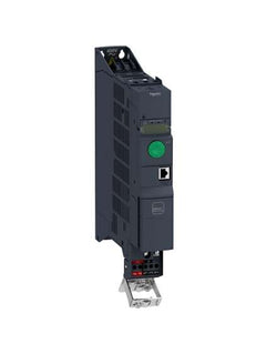
Variable Speed Drive Altivar ATV320 - 0.37kW - 380...500V - 3 Phase - book
This Altivar Process ATV600 variable speed drive can feed 3-phase synchronous and asynchronous power motors. It features 3 built-in RJ45 communication ports as standard, 1 Ethernet port, 2 serial ports. It works at a rated supply voltage from 380V to 480V AC. This drive provides up to 30% energy saving when on standby due to the innovative ââStop and Goââoperation without additional costs. It is suitable for motors with power rating up to 0.75kW / 1hp for applications requiring slight overload (up to 120%). It is suitable for motors with power rating up to 0.37kW / 0.5hp for applications requiring significant overload (up to 150%). It weighs 4.5kg and its dimensions are, 144mm wide, 350mm high, 203mm deep. This drive is focused on fluids management processing and energy saving, it offers extensive flexibility in water and wastewater, mining, minerals and metals, oil and gas and food and beverage applications. Accessories (fan kit, graphic display terminal) and options (I/O expansion modules, communication modules, EMC input filters) are available with Altivar Process ATV600 drives, depending on the drive rating. It is designed to be mounted in vertical position (+/- 10 °) on a wall. This new concept of drives meets the major needs of process and utilities in terms of equipment efficiency and total cost of ownership by supporting the energy management, asset management and also the overall performance of the process.
Main
| Characteristic | Value(s) |
|---|---|
| Range of Product | Altivar Process ATV600 |
| Product Specific Application | Process and utilities |
| Product or Component Type | Variable speed drive |
| Variant | Standard version |
| Device short name | ATV630 |
| Mounting Mode | Wall mount |
| Communication Port Protocol | Modbus TCP Ethernet Modbus serial |
| [Us] rated supply voltage | 380...480 V - 15...10 % |
| [Us] rated supply voltage | 380...480 V |
| Relative symmetric mains voltage tolerance | 10 % |
| Relative symmetric network frequency tolerance | 5 % |
| nominal output current | 2.2 A |
| IP degree of protection | IP21 |
| Product destination | Asynchronous motors Synchronous motors |
| EMC filter | Integrated 164.04 ft (50 m) IEC 61800-3 category C2 Integrated 492.1 ft (150 m) IEC 61800-3 category C3 |
| IP degree of protection | IP21IEC 61800-5-1 IP21IEC 60529 |
| Degree of protection | UL type 1 UL 508C |
| type of cooling | Forced convection |
| Supply frequency | 50...60 Hz - 5...5 % |
| Motor power kW | 0.75 kW normal duty) 0.37 kW heavy duty) |
| Maximum Horse Power Rating | 1 hp normal duty 0.5 hp heavy duty |
| Line current | 1.5 A 380 V normal duty) 1.3 A 480 V normal duty) 0.9 A 380 V heavy duty) 0.8 A 480 V heavy duty) |
| Continuous output current | 2.2 A 4 kHz normal duty 1.5 A 4 kHz heavy duty |
| Speed drive output frequency | 0.1â¦500 Hz |
| Safety function | STO (safe torque off) SIL 3 |
| Option card | Slot A communication module, Profibus DP V1 Slot A communication module, PROFINET Slot A communication module, DeviceNet Slot A communication module, Modbus TCP/EtherNet/IP Slot A communication module, CANopen daisy chain RJ45 Slot A communication module, CANopen SUB-D 9 Slot A communication module, CANopen screw terminals Slot A/slot B digital and analog I/O extension module Slot A/slot B output relay extension module Slot A communication module, Ethernet IP/Modbus TCP/MD-Link communication module, BACnet MS/TP communication module, Ethernet Powerlink |
Complementary
| Characteristic | Value(s) |
|---|---|
| Discrete input number | 8 |
| Discrete input type | DI7, DI8 programmable as pulse input 0â¦30 kHz, 24 V DC <= 30 V) |
| Discrete input logic | 16 preset speeds |
| Discrete output number | 0 |
| Discrete output type | Relay outputs R1A, R1B, R1C 250 V AC 3000 mA Relay outputs R1A, R1B, R1C 30 V DC 3000 mA Relay outputs R2A, R2C 250 V AC 5000 mA Relay outputs R2A, R2C 30 V DC 5000 mA Relay outputs R3A, R3C 250 V AC 5000 mA Relay outputs R3A, R3C 30 V DC 5000 mA |
| Analogue input number | 3 |
| Analogue input type | AI1, AI2, AI3 software-configurable voltage 0...10 V DC 31.5 kOhm 12 bits AI1, AI2, AI3 software-configurable current 0...20 mA 250 Ohm 12 bits AI2 voltage analog input - 10...10 V DC 31.5 kOhm 12 bits |
| Analogue output number | 2 |
| Analogue output type | Software-configurable voltage AQ1, AQ2 0...10 V DC 470 Ohm 10 bits Software-configurable current AQ1, AQ2 0...20 mA 10 bits Software-configurable current DQ-, DQ+ 30 V DC Software-configurable current DQ-, DQ+ 100 mA |
| Relay output number | 3 |
| Relay output type | Configurable relay logic R1 fault relay NO/NC 100000 cycles Configurable relay logic R2 sequence relay NO 100000 cycles Configurable relay logic R3 sequence relay NO 100000 cycles |
| Maximum switching current | Relay output R1, R2, R3 resistive, cos phi = 1 3 A 250 V AC Relay output R1, R2, R3 resistive, cos phi = 1 3 A 30 V DC Relay output R1, R2, R3 inductive, cos phi = 0.4 7 ms 2 A 250 V AC Relay output R1, R2, R3 inductive, cos phi = 0.4 7 ms 2 A 30 V DC |
| Minimum switching current | Relay output R1, R2, R3 5 mA 24 V DC |
| Phase | 3 phase |
| Physical interface | Ethernet 2-wire RS 485 |
| Method of access | Slave Modbus TCP |
| Transmission Rate | 10, 100 Mbits 4800 bps, 9600 bps, 19200 bps, 38.4 Kbps |
| Transmission frame | RTU |
| Output voltage | <= power supply voltage |
| Permissible temporary current boost | 1.1 x In 60 s normal duty) 1.5 x In 60 s heavy duty) |
| Data format | 8 bits, configurable odd, even or no parity |
| Type of polarization | No impedance |
| Frequency resolution | Display unit 0.1 Hz Analog input 0.012/50 Hz |
| Electrical connection | Control removable screw terminals 0.5...1.5 mm² AWG 20...AWG 16 Motor screw terminal 2.5...6 mm² AWG 14...AWG 10 Line side screw terminal 2.5...6 mm² AWG 14...AWG 10 |
| Connector type | RJ45 on the remote graphic terminal)Ethernet/Modbus TCP RJ45 on the remote graphic terminal)Modbus serial |
| Exchange mode | Half duplex, full duplex, autonegotiation Ethernet/Modbus TCP |
| Number of addresses | 1â¦247 Modbus serial |
| Supply | External supply for digital inputs 24 V DC 19â¦30 V), <1.25 mA overload and short-circuit protection Internal supply for reference potentiometer (1 to 10 kOhm) 10.5 V DC +/- 5 %, <10 mA overload and short-circuit protection Internal supply for digital inputs and STO 24 V DC 21â¦27 V), <200 mA overload and short-circuit protection |
| Local signalling | 3 LEDs for local diagnostic 3 LEDs (dual colour) for embedded communication status 4 LEDs (dual colour) for communication module status 1 LED (red) for presence of voltage |
| Input compatibility | DI1...DI6 discrete input level 1 PLC IEC 61131-2 DI5, DI6 discrete input level 1 PLC IEC 65A-68 STOA, STOB discrete input level 1 PLC IEC 61131-2 |
| Discrete input logic | Positive logic (source) DI1...DI8), < 5 V, > 11 V Negative logic (sink) DI1...DI8), > 16 V, < 10 V |
| Sampling duration | 2 ms +/- 0.5 ms DI1...DI4) - discrete input 5 ms +/- 1 ms DI5, DI6) - discrete input 5 ms +/- 0.1 ms AI1, AI2, AI3) - analog input 10 ms +/- 1 ms AO1) - analog output |
| Accuracy | +/- 0.6 % AI1, AI2, AI3 for a temperature variation 60 °C analog input +/- 1 % AO1, AO2 for a temperature variation 60 °C analog output |
| Linearity error | AI1, AI2, AI3 +/- 0.15 % of maximum value analog input AO1, AO2 +/- 0.2 % analog output |
| Refresh time | Relay output R1, R2, R3)5 ms +/- 0.5 ms) |
| Isolation | Between power and control terminals |
| Discrete and process manufacturing | Building - HVAC compressor centrifugal Food and beverage processing other application Mining mineral and metal fan Mining mineral and metal pump Oil and gas fan Water and waste water other application Building - HVAC screw compressor Food and beverage processing pump Food and beverage processing fan Food and beverage processing atomization Oil and gas electro submersible pump (ESP) Oil and gas water injection pump Oil and gas jet fuel pump Oil and gas compressor for refinery Water and waste water centrifuge pump Water and waste water positive displacement pump Water and waste water electro submersible pump (ESP) Water and waste water screw pump Water and waste water lobe compressor Water and waste water screw compressor Water and waste water compressor centrifugal Water and waste water fan Water and waste water conveyor Water and waste water mixer |
| Power range | 0.55â¦1 kW 380â¦440 V 3 phase 0.55â¦1 kW 480â¦500 V 3 phase |
| Enclosure mounting | Wall mounted |
| 4 quadrant operation possible | False |
| Asynchronous motor control profile | Constant torque standard Variable torque standard Optimized torque mode |
| Synchronous motor control profile | Permanent magnet motor Synchronous reluctance motor |
| Maximum output frequency | 500 kHz |
| Acceleration and deceleration ramps | Linear adjustable separately from 0.01...9999 s |
| Motor slip compensation | Not available in permanent magnet motor law Can be suppressed Automatic whatever the load Adjustable |
| Switching frequency | 2...12 kHz adjustable 4...12 kHz with derating factor |
| Nominal switching frequency | 4 kHz |
| Braking to standstill | By DC injection |
| Brake chopper integrated | False |
| Maximum Input Current per Phase | 1.5 A |
| Maximum output voltage | 480.0 V |
| Apparent power | 1.1 kVA 480 V normal duty) 0.7 kVA 480 V heavy duty) |
| Maximum transient current | 2.4 A 60 s normal duty) 2.3 A 60 s heavy duty) |
| Network Frequency | 50-60 Hz |
| Prospective line Isc | 50 kA |
| Base load current at high overload | 1.5 A |
| Base load current at low overload | 2.2 A |
| Power dissipation in W | Natural convection 26 W 380 V 4 kHz Forced convection 21 W 380 V 4 kHz |
| With safety function Safely Limited Speed (SLS) | False |
| With safety function Safe brake management (SBC/SBT) | False |
| With safety function Safe Operating Stop (SOS) | False |
| With safety function Safe Position (SP) | False |
| With safety function Safe programmable logic | False |
| With safety function Safe Speed Monitor (SSM) | False |
| With safety function Safe Stop 1 (SS1) | False |
| With sft fct Safe Stop 2 (SS2) | False |
| With safety function Safe torque off (STO) | True |
| With safety function Safely Limited Position (SLP) | False |
| With safety function Safe Direction (SDI) | False |
| Protection type | Thermal protection motor Safe torque off motor Motor phase break motor Thermal protection drive Safe torque off drive Overheating drive Overcurrent between output phases and earth drive Overload of output voltage drive Short-circuit protection drive Motor phase break drive Overvoltages on the DC bus drive Line supply overvoltage drive Line supply undervoltage drive Line supply phase loss drive Overspeed drive Break on the control circuit drive |
| Quantity per Set | 1 |
| Width | 5.7 in (144 mm) |
| Height | 13.8 in (350 mm) |
| Depth | 8.0 in (203 mm) |
| Product Weight | 9.9 lb(US) (4.5 kg) |
Variable Speed Drive - 22kW- 400V - 3 Phases - Altivar ATV340
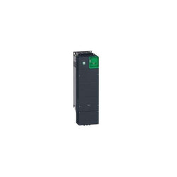
This Altivar 340 variable speed drive can feed 3-phase synchronous and asynchronous motors in open and closed loop control. Altivar Machine ATV340 drives are sized heavy duty as standard. It works at a rated power up to 45kW / 60hp and a rated voltage from 380V to 480V AC. ATV340 has been designed to meet the needs of applications for harsh environments, such as vibration, shock and non-conductive dust and where high temperature resistance up to 60 °C is needed. This product integrates Modbus serial line communication protocols as standard. This drive features multi-protocol Ethernet embedded, it consists of Ethernet IP and Modbus TCP communication interfaces. it weighs 56.4kg and its dimensions are, 271mm wide, 908mm high, 309mm deep. ATV340 incorporates functions and features suitable for the most common applications, including packaging, material handling, material working, hoisting. It conforms to international standards IEC/EN 61800-5-1 and IEC/EN 61800-3 (immunity and conducted and radiated EMC emissions), IEC 60721-3, IEC 61508, IEC 13849-1. It is also CE, UL, CSA, and TÃV certified. Accessories and options (encoder interface modules, I/O expansion modules, communication modules, braking resistors, line chokes, additional EMC filters) are available with Altivar Machine ATV340 drives, depending on the drive rating. It is designed to be mounted in vertical position (+/- 10 °) on a panel, thanks to 4 fixing holes. It is fully integrated inside Schneider Electricâs EcoStruxure Machine through DTM. It is possible to configure, control, and diagnose ATV340 drives directly in SoMachine and SoMove software by means of the same software brick (DTM).
Main
| Characteristic | Value(s) |
|---|---|
| Range of Product | Altivar Machine ATV340 |
| Product or Component Type | Variable speed drive |
| Product Specific Application | Machine |
| Mounting Mode | Wall mount |
| Variant | Standard version |
| Communication Port Protocol | Modbus TCP Modbus serial EtherNet/IP |
| Option card | communication module, PROFINET communication module, DeviceNet communication module, CANopen communication module, EtherCAT |
| Phase | 3 phase |
| Supply frequency | 50...60 Hz +/- 5 % |
| [Us] rated supply voltage | 380...480 V - 15...10 % |
| nominal output current | 88.0 A |
| Motor power kW | 55 kW normal duty 45 kW heavy duty |
| Maximum Horse Power Rating | 75 hp normal duty 60 hp heavy duty |
| EMC filter | Class C3 EMC filter integrated |
| IP degree of protection | IP20 |
| Degree of protection | UL type 1 |
Complementary
| Characteristic | Value(s) |
|---|---|
| Discrete input number | 8 |
| Discrete input type | PTI safe torque off 0â¦30 kHz, 24 V DC 30 V) DI1...DI5 programmable as pulse input, 24 V DC 30 V)3.5 kOhm programmable |
| number of preset speeds | 16 preset speeds |
| Discrete output number | 1.0 |
| Discrete output type | Programmable output DQ1, DQ2 30 V DC 100 mA |
| Analogue input number | 3 |
| Analogue input type | AI1 software-configurable current 0...20 mA 250 Ohm 12 bits AI1 software-configurable temperature probe or water level sensor AI1 software-configurable voltage 0...10 V DC 31.5 kOhm 12 bits AI2 software-configurable voltage - 10...10 V DC 31.5 kOhm 12 bits |
| Analogue output number | 2 |
| Analogue output type | Software-configurable voltage AQ1, AQ2 0...10 V DC 470 Ohm 10 bits Software-configurable current AQ1, AQ2 0...20 mA 500 Ohm 10 bits |
| Relay output number | 3 |
| Output voltage | <= power supply voltage |
| Relay output type | Relay outputs R1A Relay outputs R1C 100000 cycles Relay outputs R2A Relay outputs R2C 100000 cycles |
| Maximum switching current | Relay output R1C resistive, cos phi = 1 3 A 250 V AC Relay output R1C resistive, cos phi = 1 3 A 30 V DC Relay output R1C inductive, cos phi = 0.4 7 ms 2 A 250 V AC Relay output R1C inductive, cos phi = 0.4 7 ms 2 A 30 V DC Relay output R2C resistive, cos phi = 1 5 A 250 V AC Relay output R2C resistive, cos phi = 1 5 A 30 V DC Relay output R2C inductive, cos phi = 0.4 7 ms 2 A 250 V AC Relay output R2C inductive, cos phi = 0.4 7 ms 2 A 30 V DC |
| Minimum switching current | Relay output R1B 5 mA 24 V DC Relay output R2C 5 mA 24 V DC |
| Physical interface | 2-wire RS 485 |
| Connector Type | 3 RJ45 |
| Method of access | Slave Modbus RTU Slave Modbus TCP |
| Transmission Rate | 4.8 kbit/s 9.6 kbit/s 19.2 kbit/s 38.4 kbit/s |
| Transmission frame | RTU |
| Number of addresses | 1â¦247 |
| Data format | 8 bits, configurable odd, even or no parity |
| Type of polarization | No impedance |
| 4 quadrant operation possible | True |
| Asynchronous motor control profile | Constant torque standard Optimized torque mode Variable torque standard |
| Synchronous motor control profile | Reluctance motor Permanent magnet motor |
| Pollution degree | 2 IEC 61800-5-1 |
| Maximum output frequency | 0.599 kHz |
| Acceleration and deceleration ramps | S, U or customized Linear adjustable separately from 0.01...9999 s |
| Motor slip compensation | Not available in permanent magnet motor law Can be suppressed Adjustable Automatic whatever the load |
| Switching frequency | 1...8 kHz adjustable 2.5...8 kHz with derating factor |
| Nominal switching frequency | 2.5 kHz |
| Braking to standstill | By DC injection |
| Brake chopper integrated | True |
| Line current | 97.2 A 380 V normal duty) 84.2 A 480 V normal duty) 81.4 A 380 V heavy duty) 71.8 A 480 V heavy duty) |
| Line current | 97.2 A 380 V with internal line choke normal duty) 84.2 A 480 V with internal line choke normal duty) 81.4 A 380 V with internal line choke heavy duty) 71.8 A 480 V with internal line choke heavy duty) 81.4 A 71.8 A |
| Maximum Input Current per Phase | 97.2 A |
| Maximum output voltage | 480 V |
| Apparent power | 70 kVA 480 V normal duty) 59.7 kVA 480 V heavy duty) |
| Maximum transient current | 127.2 A 60 s normal duty) 132 A 60 s heavy duty) 127.2 A 2 s normal duty) 132 A 2 s heavy duty) |
| Electrical connection | Screw terminal 0.75...1.5 mm² control Screw terminal 70...120 mm² line side Screw terminal 70...120 mm² DC bus Screw terminal 70...120 mm² motor |
| Prospective line Isc | 50 kA |
| Base load current at high overload | 88.0 A |
| Base load current at low overload | 106.0 A |
| Power dissipation in W | Natural convection 105 W 380 V 4 kHz heavy duty) Forced convection 943 W 380 V 4 kHz heavy duty) Natural convection 115 W 380 V 4 kHz normal duty) Forced convection 917 W 380 V 4 kHz normal duty) |
| Electrical connection | Control screw terminal 0.75...1.5 mm² AWG 18...AWG 16 Line side screw terminal 70...120 mm² AWG 1/0...250 kcmil DC bus screw terminal 70...120 mm² AWG 1/0...250 kcmil Motor screw terminal 70...120 mm² AWG 1/0...250 kcmil |
| With safety function Safely Limited Speed (SLS) | True |
| With safety function Safe brake management (SBC/SBT) | True |
| With safety function Safe Operating Stop (SOS) | False |
| With safety function Safe Position (SP) | False |
| With safety function Safe programmable logic | False |
| With safety function Safe Speed Monitor (SSM) | False |
| With safety function Safe Stop 1 (SS1) | True |
| With sft fct Safe Stop 2 (SS2) | False |
| With safety function Safe torque off (STO) | True |
| With safety function Safely Limited Position (SLP) | False |
| With safety function Safe Direction (SDI) | False |
| Protection type | Thermal protection motor Safe torque off motor Motor phase loss motor Thermal protection drive Safe torque off drive Overheating drive Overcurrent drive Output overcurrent between motor phase and earth drive Output overcurrent between motor phases drive Short-circuit between motor phase and earth drive Short-circuit between motor phases drive Motor phase loss drive DC Bus overvoltage drive Line supply overvoltage drive Line supply undervoltage drive Input supply loss drive Exceeding limit speed drive Break on the control circuit drive |
| Width | 10.7 in (271.0 mm) |
| Height | 35.7 in (908.0 mm) |
| Depth | 12.2 in (309.0 mm) |
| Product Weight | 124.3 lb(US) (56.4 kg) |
| Continuous output current | 106 A 4 kHz normal duty 88 A 4 kHz heavy duty |
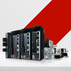
1S servo drive EtherCAT type 1.5 kW 1~ 230 VAC
1S AC servo motor 2 kW 400 VAC 3000 rpm 6.37 Nm absolute encoder with brake
Specialised Cables PC MONITORING CABLE