
 1 year warranty


PLC Direct is not an authorized distributor. We offer a broad range of in-stock products with minimal lead time.

PLC Direct is not an authorized distributor. We offer a broad range of in-stock products with minimal lead time.
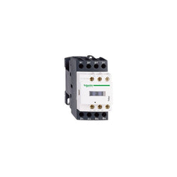
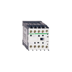
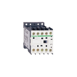
TeSys D contactor - 4P(4 NO) - AC-1 - <= 440 V 20 A - 110 V AC 50/60 Hz coil
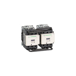
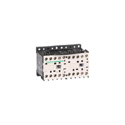
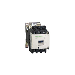
TeSys D reversing contactor - 3P(3 NO) - AC-3 - <= 440 V 80 A - 220 V AC coil

Main
| Characteristic | Value(s) |
|---|---|
| Range | TeSys |
| Range of Product | TeSys Deca |
| Product or Component Type | Contactor |
| Device short name | LC1D |
| Contactor application | Resistive load |
| Utilisation category | AC-1 |
| Poles description | 4P |
| [Ue] rated operational voltage | Power circuit <= 690 V AC 25...400 Hz Power circuit <= 300 V DC |
| [Ie] rated operational current | 80 A (at <140 °F (60 °C)) at <= 440 V AC AC-1 for power circuit |
| [Uc] control circuit voltage | 42 V AC 50/60 Hz |
Complementary
| Characteristic | Value(s) |
|---|---|
| Compatibility code | LC1D |
| Pole contact composition | 4 NO |
| Protective cover | With |
| [Ith] conventional free air thermal current | 10 A (at 140 °F (60 °C)) for signalling circuit 80 A (at 140 °F (60 °C)) for power circuit |
| Irms rated making capacity | 140 A AC for signalling circuit conforming to IEC 60947-5-1 250 A DC for signalling circuit conforming to IEC 60947-5-1 1000 A at 440 V for power circuit conforming to IEC 60947 |
| Rated breaking capacity | 1000 A at 440 V for power circuit conforming to IEC 60947 |
| [Icw] rated short-time withstand current | 640 A 104 °F (40 °C) - 10 s for power circuit 900 A 104 °F (40 °C) - 1 s for power circuit 110 A 104 °F (40 °C) - 10 min for power circuit 260 A 104 °F (40 °C) - 1 min for power circuit 100 A - 1 s for signalling circuit 120 A - 500 ms for signalling circuit 140 A - 100 ms for signalling circuit |
| Associated fuse rating | 10 A gG for signalling circuit conforming to IEC 60947-5-1 125 A gG at <= 690 V coordination type 1 for power circuit 125 A gG at <= 690 V coordination type 2 for power circuit |
| Average impedance | 1.6 mOhm - Ith 80 A 50 Hz for power circuit |
| Power dissipation per pole | 10.2 W AC-1 |
| [Ui] rated insulation voltage | Power circuit 600 V CSA Power circuit 600 V UL Signalling circuit 690 V IEC 60947-1 Signalling circuit 600 V CSA Signalling circuit 600 V UL Power circuit 690 V IEC 60947-4-1 |
| Overvoltage category | III |
| pollution degree | 3 |
| [Uimp] rated impulse withstand voltage | 6 kV IEC 60947 |
| Safety reliability level | B10d = 1369863 cycles contactor with nominal load EN/ISO 13849-1 B10d = 20000000 cycles contactor with mechanical load EN/ISO 13849-1 |
| Mechanical durability | 6 Mcycles |
| Electrical durability | 1.4 Mcycles 80 A AC-1 <= 440 V |
| Control circuit type | AC 50/60 Hz |
| Coil technology | Without built-in suppressor module |
| Control circuit voltage limits | 0.3...0.6 Uc (-40â¦158 °F (-40â¦70 °C)):drop-out AC 50/60 Hz 0.8...1.1 Uc (-40â¦140 °F (-40â¦60 °C)):operational AC 50 Hz 0.85...1.1 Uc (-40â¦140 °F (-40â¦60 °C)):operational AC 60 Hz 1...1.1 Uc (140â¦158 °F (60â¦70 °C)):operational AC 50/60 Hz |
| Inrush power in VA | 140 VA 60 Hz cos phi 0.75 (at 68 °F (20 °C)) 160 VA 50 Hz cos phi 0.75 (at 68 °F (20 °C)) |
| Hold-in power consumption in VA | 13 VA 60 Hz cos phi 0.3 (at 68 °F (20 °C)) 15 VA 50 Hz cos phi 0.3 (at 68 °F (20 °C)) |
| Heat dissipation | 4â¦5 W at 50/60 Hz |
| Operating time | 4...19 ms opening 12...26 ms closing |
| Connections - terminals | Control circuit: spring terminals 1 0.004 in² (2.5 mm²) - cable stiffness: flexible without cable end Control circuit: spring terminals 2 0.004 in² (2.5 mm²) - cable stiffness: flexible without cable end Power circuit: EverLink BTR screw connectors 1 0.002â¦0.05 in² (1â¦35 mm²) - cable stiffness: flexible without cable end Power circuit: EverLink BTR screw connectors 2 0.002â¦0.04 in² (1â¦25 mm²) - cable stiffness: flexible without cable end Power circuit: EverLink BTR screw connectors 1 0.002â¦0.05 in² (1â¦35 mm²) - cable stiffness: flexible with cable end Power circuit: EverLink BTR screw connectors 2 0.002â¦0.04 in² (1â¦25 mm²) - cable stiffness: flexible with cable end Power circuit: EverLink BTR screw connectors 1 0.002â¦0.05 in² (1â¦35 mm²) - cable stiffness: solid without cable end Power circuit: EverLink BTR screw connectors 2 0.002â¦0.04 in² (1â¦25 mm²) - cable stiffness: solid without cable end |
| Tightening torque | Power circuit 70.8 lbf.in (8 N.m) EverLink BTR screw connectors 0.04â¦0.05 in² (25â¦35 mm²) hexagonal 0.2 in (4 mm) Power circuit 44.3 lbf.in (5 N.m) EverLink BTR screw connectors 0.004â¦0.04 in² (2.5â¦25 mm²) hexagonal 0.2 in (4 mm) |
| Auxiliary contact composition | 1 NO + 1 NC |
| Auxiliary contacts type | Mechanically linked 1 NO + 1 NC IEC 60947-5-1 Mirror contact 1 NC IEC 60947-4-1 |
| Signalling circuit frequency | 25...400 Hz |
| Minimum switching voltage | 17 V for signalling circuit |
| Minimum switching current | 5 mA for signalling circuit |
| Insulation resistance | > 10 MOhm for signalling circuit |
| Non-overlap time | 1.5 ms on de-energisation between NC and NO contact 1.5 ms on energisation between NC and NO contact |
| Mounting Support | Rail Plate |
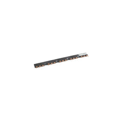
Linergy FT - Comb busbar - 63 A - 5 tap-offs - 54 mm pitch

TeSys Deca contactor, 3 poles (3NO), for motor control applications up to 18A/690V AC-3/3e (7.5kW@400V). They can be used to create motor starters for almost any type of application. It provides a 48V 50/60Hz AC coil, 1NO+1NC built-in auxiliary contacts (NC mirror certified), connection by screw clamp terminals. For operating rates until 3600 cycles/hour and environments until 60°C, it procures high reliability and durability. Compact (45mm width), DIN-rail mounting or screw fixing. Contactor is rated for 5HP at 200-208VAC, 5HP at 240VAC, 10HP at 480VAC and 15HP at 600VAC three phase. Multi standards certified (IEC, UL, CSA, CCC, EAC, Marine). When used with a 480VAC up to 60A circuit breaker, this contactor can have a SCCR up to 85kA. When used with up to a 600VAC 40A Class J or CC fuse, this contactor can have a SCCR up to 100kA. Contactor is supplied with a 48 VAC 50/60 Hz coil. Contactor has one normally open and one normally closed auxiliary contact built-in as standard. The NC contact is mirror certified. Screw clamp terminals are used for load and auxiliary connections. An extensive line of accessories makes it easy to meet the requirements of most applications. The contactor is 3.03 inches tall, 1.77 inches wide and 3.39 inches deep. It weighs 0.73 lbs. Contactor is certified to UL, CSA, IEC, CCC, EAC and Marine standards.
Main
| Characteristic | Value(s) |
|---|---|
| Range of Product | TeSys Deca |
| Product or Component Type | Contactor |
| Device short name | LC1D |
| Contactor application | Resistive load Motor control |
| Utilisation category | AC-4 AC-1 AC-3 AC-3e |
| Poles description | 3P |
| [Ue] rated operational voltage | Power circuit <= 690 V AC 25...400 Hz Power circuit <= 300 V DC |
| [Ie] rated operational current | 18 A (at <140 °F (60 °C)) at <= 440 V AC AC-3 for power circuit 32 A (at <140 °F (60 °C)) at <= 440 V AC AC-1 for power circuit 18 A (at <140 °F (60 °C)) at <= 440 V AC AC-3e for power circuit |
| [Uc] control circuit voltage | 48 V AC 50/60 Hz |
Complementary
| Characteristic | Value(s) |
|---|---|
| Motor power kW | 4 kW at 220...230 V AC 50/60 Hz (AC-3) 7.5 kW at 380...400 V AC 50/60 Hz (AC-3) 9 kW at 415...440 V AC 50/60 Hz (AC-3) 10 kW at 500 V AC 50/60 Hz (AC-3) 10 kW at 660...690 V AC 50/60 Hz (AC-3) 4 kW at 400 V AC 50/60 Hz (AC-4) 4 kW at 220...230 V AC 50/60 Hz (AC-3e) 7.5 kW at 380...400 V AC 50/60 Hz (AC-3e) 9 kW at 415...440 V AC 50/60 Hz (AC-3e) 10 kW at 500 V AC 50/60 Hz (AC-3e) 10 kW at 660...690 V AC 50/60 Hz (AC-3e) |
| Maximum Horse Power Rating | 1 hp at 115 V AC 50/60 Hz for 1 phase motors 3 hp at 230/240 V AC 50/60 Hz for 1 phase motors 5 hp at 200/208 V AC 50/60 Hz for 3 phase motors 5 hp at 230/240 V AC 50/60 Hz for 3 phase motors 10 hp at 460/480 V AC 50/60 Hz for 3 phase motors 15 hp at 575/600 V AC 50/60 Hz for 3 phase motors |
| Compatibility code | LC1D |
| Pole contact composition | 3 NO |
| Protective cover | With |
| [Ith] conventional free air thermal current | 10 A (at 140 °F (60 °C)) for signalling circuit 32 A (at 140 °F (60 °C)) for power circuit |
| Irms rated making capacity | 140 A AC for signalling circuit conforming to IEC 60947-5-1 250 A DC for signalling circuit conforming to IEC 60947-5-1 300 A at 440 V for power circuit conforming to IEC 60947 |
| Rated breaking capacity | 300 A at 440 V for power circuit conforming to IEC 60947 |
| [Icw] rated short-time withstand current | 145 A 104 °F (40 °C) - 10 s for power circuit 240 A 104 °F (40 °C) - 1 s for power circuit 40 A 104 °F (40 °C) - 10 min for power circuit 84 A 104 °F (40 °C) - 1 min for power circuit 100 A - 1 s for signalling circuit 120 A - 500 ms for signalling circuit 140 A - 100 ms for signalling circuit |
| Associated fuse rating | 10 A gG for signalling circuit conforming to IEC 60947-5-1 50 A gG at <= 690 V coordination type 1 for power circuit 35 A gG at <= 690 V coordination type 2 for power circuit |
| Average impedance | 2.5 mOhm - Ith 32 A 50 Hz for power circuit |
| Power dissipation per pole | 2.5 W AC-1 0.8 W AC-3 0.8 W AC-3e |
| [Ui] rated insulation voltage | Power circuit 690 V IEC 60947-4-1 Power circuit 600 V CSA Power circuit 600 V UL Signalling circuit 690 V IEC 60947-1 Signalling circuit 600 V CSA Signalling circuit 600 V UL |
| Overvoltage category | III |
| pollution degree | 3 |
| [Uimp] rated impulse withstand voltage | 6 kV IEC 60947 |
| Safety reliability level | B10d = 1369863 cycles contactor with nominal load EN/ISO 13849-1 B10d = 20000000 cycles contactor with mechanical load EN/ISO 13849-1 |
| Mechanical durability | 15 Mcycles |
| Electrical durability | 1.65 Mcycles 18 A AC-3 <= 440 V 1 Mcycles 32 A AC-1 <= 440 V 1.65 Mcycles 18 A AC-3e <= 440 V |
| Control circuit type | AC 50/60 Hz standard |
| Coil technology | Without built-in suppressor module |
| Control circuit voltage limits | 0.3...0.6 Uc (-40â¦158 °F (-40â¦70 °C)):drop-out AC 50/60 Hz 0.8...1.1 Uc (-40â¦140 °F (-40â¦60 °C)):operational AC 50 Hz 0.85...1.1 Uc (-40â¦140 °F (-40â¦60 °C)):operational AC 60 Hz 1...1.1 Uc (140â¦158 °F (60â¦70 °C)):operational AC 50/60 Hz |
| Inrush power in VA | 70 VA 60 Hz cos phi 0.75 (at 68 °F (20 °C)) 70 VA 50 Hz cos phi 0.75 (at 68 °F (20 °C)) |
| Hold-in power consumption in VA | 7.5 VA 60 Hz cos phi 0.3 (at 68 °F (20 °C)) 7 VA 50 Hz cos phi 0.3 (at 68 °F (20 °C)) |
| Heat dissipation | 2â¦3 W at 50/60 Hz |
| Operating time | 12...22 ms closing 4...19 ms opening |
| Maximum operating rate | 3600 cyc/h at 60 °C |
| Connections - terminals | Control circuit: screw clamp terminals 1 0.002â¦0.006 in² (1â¦4 mm²) - cable stiffness: flexible without cable end Control circuit: screw clamp terminals 2 0.002â¦0.006 in² (1â¦4 mm²) - cable stiffness: flexible without cable end Control circuit: screw clamp terminals 1 0.002â¦0.006 in² (1â¦4 mm²) - cable stiffness: flexible with cable end Control circuit: screw clamp terminals 2 0.002â¦0.004 in² (1â¦2.5 mm²) - cable stiffness: flexible with cable end Control circuit: screw clamp terminals 1 0.002â¦0.006 in² (1â¦4 mm²) - cable stiffness: solid without cable end Control circuit: screw clamp terminals 2 0.002â¦0.006 in² (1â¦4 mm²) - cable stiffness: solid without cable end Power circuit: screw clamp terminals 1 0.002â¦0.009 in² (1.5â¦6 mm²) - cable stiffness: flexible without cable end Power circuit: screw clamp terminals 2 0.002â¦0.009 in² (1.5â¦6 mm²) - cable stiffness: flexible without cable end Power circuit: screw clamp terminals 1 0.002â¦0.009 in² (1â¦6 mm²) - cable stiffness: flexible with cable end Power circuit: screw clamp terminals 2 0.002â¦0.006 in² (1â¦4 mm²) - cable stiffness: flexible with cable end Power circuit: screw clamp terminals 1 0.002â¦0.009 in² (1.5â¦6 mm²) - cable stiffness: solid without cable end Power circuit: screw clamp terminals 2 0.002â¦0.009 in² (1.5â¦6 mm²) - cable stiffness: solid without cable end |
| Tightening torque | Power circuit 15.05 lbf.in (1.7 N.m) screw clamp terminals flat à 6 mm Power circuit 15.05 lbf.in (1.7 N.m) screw clamp terminals Philips No 2 Control circuit 15.05 lbf.in (1.7 N.m) screw clamp terminals flat à 6 mm Control circuit 15.05 lbf.in (1.7 N.m) screw clamp terminals Philips No 2 Control circuit 15.05 lbf.in (1.7 N.m) screw clamp terminals pozidriv No 2 Power circuit 15.05 lbf.in (1.7 N.m) screw clamp terminals pozidriv No 2 |
| Auxiliary contact composition | 1 NO + 1 NC |
| Auxiliary contacts type | Mechanically linked 1 NO + 1 NC IEC 60947-5-1 Mirror contact 1 NC IEC 60947-4-1 |
| Signalling circuit frequency | 25...400 Hz |
| Minimum switching voltage | 17 V for signalling circuit |
| Minimum switching current | 5 mA for signalling circuit |
| Insulation resistance | > 10 MOhm for signalling circuit |
| Non-overlap time | 1.5 ms on de-energisation between NC and NO contact 1.5 ms on energisation between NC and NO contact |
| Mounting Support | Rail Plate |
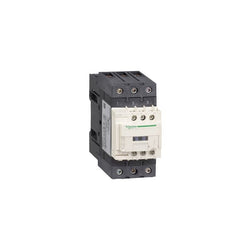
TeSys D contactor - 3P(3 NO) - AC-3 - <= 440 V 50 A - 400 V AC 50/60 Hz coil
TeSys K contactor - 3P - AC-3 <= 440 V 6 A - 1 NC aux. - 24 V AC coil
Main
| Characteristic | Value(s) |
|---|---|
| Range | TeSys |
| product name | TeSys K |
| Product or Component Type | Reversing contactor |
| Device short name | LP2K |
| Device Application | Control |
| Contactor application | Resistive load Motor control |
| Utilisation category | AC-4 AC-3 AC-1 |
| Device presentation | Preassembled with reversing power busbar |
| Poles description | 3P |
| power pole contact composition | 3 NO |
| [Ue] rated operational voltage | Power circuit 690 V AC 50/60 Hz Signalling circuit <= 690 V AC 50/60 Hz |
| [Ie] rated operational current | 20 A (at <122 °F (50 °C)) at <= 440 V AC AC-1 for power circuit 16 A (at <158 °F (70 °C)) at 690 V AC AC-1 for power circuit 9 A at <= 440 V AC AC-3 for power circuit |
| Motor power kW | 2.2 kW 220...230 V AC 50/60 Hz 4 kW 380...415 V AC 50/60 Hz 4 kW 440 V AC 50/60 Hz 4 kW 480 V AC 50/60 Hz 4 kW 500...600 V AC 50/60 Hz 4 kW 660...690 V AC 50/60 Hz |
| Control circuit type | DC standard |
| [Uc] control circuit voltage | 60 V DC |
| Auxiliary contact composition | 1 NO |
| [Uimp] rated impulse withstand voltage | 8 kV |
| Overvoltage category | III |
| [Ith] conventional free air thermal current | 20 A (at 122 °F (50 °C)) for power circuit 10 A (at 122 °F (50 °C)) for signalling circuit |
| Irms rated making capacity | 110 A AC for power circuit conforming to NF C 63-110 110 A AC for power circuit conforming to IEC 60947 110 A AC for signalling circuit conforming to IEC 60947 |
| Rated breaking capacity | 110 A at 415 V conforming to IEC 60947 110 A at 440 V conforming to IEC 60947 80 A at 500 V conforming to IEC 60947 110 A at 220...230 V conforming to IEC 60947 110 A at 380...400 V conforming to IEC 60947 70 A at 660...690 V conforming to IEC 60947 |
| [Icw] rated short-time withstand current | 90 A 122 °F (50 °C) - 1 s for power circuit 85 A 122 °F (50 °C) - 5 s for power circuit 80 A 122 °F (50 °C) - 10 s for power circuit 60 A 122 °F (50 °C) - 30 s for power circuit 45 A 122 °F (50 °C) - 1 min for power circuit 40 A 122 °F (50 °C) - 3 min for power circuit 80 A - 1 s for signalling circuit 90 A - 500 ms for signalling circuit 110 A - 100 ms for signalling circuit 20 A 122 °F (50 °C) - >= 15 min for power circuit |
| Associated fuse rating | 25 A gG at <= 440 V for power circuit 25 A aM for power circuit 10 A gG for signalling circuit conforming to IEC 60947 10 A gG for signalling circuit conforming to VDE 0660 |
| Average impedance | 3 mOhm - Ith 20 A 50 Hz for power circuit |
| [Ui] rated insulation voltage | Power circuit 600 V UL 508 Power circuit 690 V IEC 60947-4-1 Signalling circuit 690 V IEC 60947-4-1 Signalling circuit 690 V IEC 60947-5-1 Signalling circuit 600 V UL 508 Power circuit 600 V CSA C22.2 No 14 Signalling circuit 600 V CSA C22.2 No 14 |
| Electrical durability | 0.18 Mcycles 20 A AC-1 <= 440 V 1.3 Mcycles 9 A AC-3 <= 440 V |
| Interlocking type | Mechanical |
| Mounting Support | Rail Plate |
| Standards | EN/IEC 60947-4-1 GB/T 14048.4 UL 60947-4-1 CSA C22.2 No 60947-4-1 JIS C8201-4-1 |
| Product Certifications | CB Scheme CCC UL CSA EAC CE UKCA |
| Connections - terminals | screw clamp terminals 1 0.002â¦0.006 in² (1.5â¦4 mm²)solid screw clamp terminals 1 0.001â¦0.006 in² (0.75â¦4 mm²)flexible without cable end screw clamp terminals 1 0.0005â¦0.004 in² (0.34â¦2.5 mm²)flexible with cable end screw clamp terminals 2 0.002â¦0.006 in² (1.5â¦4 mm²)solid screw clamp terminals 2 0.001â¦0.006 in² (0.75â¦4 mm²)flexible without cable end screw clamp terminals 2 0.0005â¦0.002 in² (0.34â¦1.5 mm²)flexible with cable end |
| Tightening torque | 7.08â¦11.5 lbf.in (0.8â¦1.3 N.m) screw clamp terminals Philips No 2 7.08â¦11.5 lbf.in (0.8â¦1.3 N.m) screw clamp terminals flat à 6 mm |
| Operating time | 30...40 ms coil energisation and NO closing 10 ms coil de-energisation and NO opening |
| Safety reliability level | B10d = 1369863 cycles contactor with nominal load EN/ISO 13849-1 B10d = 20000000 cycles contactor with mechanical load EN/ISO 13849-1 |
| Mechanical durability | 5 Mcycles |
| Maximum operating rate | 3600 cyc/h |
Complementary
| Characteristic | Value(s) |
|---|---|
| Control circuit voltage limits | Operational: 0.8...1.15 Uc (at <122 °F (50 °C)) Drop-out: 0.1...0.75 Uc (at <122 °F (50 °C)) |
| Inrush power in W | 3 W 68 °F (20 °C)) |
| Hold-in power consumption in W | 3 W 68 °F (20 °C) |
| Heat dissipation | 3 W |
| Auxiliary contacts type | Instantaneous 1 NO |
| Minimum switching current | 5 mA for signalling circuit |
| Minimum switching voltage | 17 V for signalling circuit |
| Non overlap distance | 0.02 in (0.5 mm) |
| Insulation resistance | > 10 MOhm for signalling circuit |
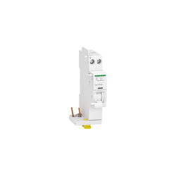
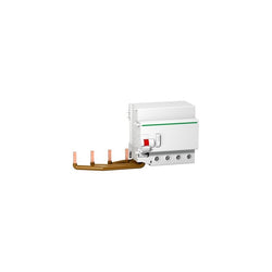
add-on residual current devices, Acti9 Vigi iCG40, 1P+N, 40 A, 300 mA, AC type

PLC Direct is not an authorized distributor. We offer a broad range of in-stock products with minimal lead time.

PLC Direct is not an authorized distributor. We offer a broad range of in-stock products with minimal lead time.

TeSys D contactor - 4P(4 NO) - AC-1 - <= 440 V 20 A - 220 V AC 50/60 Hz coil

This Acti9 C60H-DC is a low voltage direct current miniature circuit breaker (MCB). It has 1P, rated current 32A and C tripping curve. The rated short circuit breaking capacity goes up to 10kA at 220VDC conforming to EN 60947-2 standard and 10kA at 220VDC conforming to EN 60947-2 standard. This product complies with both industrial standard EN/IEC 60898-1 and residential standard EN/IEC 60947-2. This miniature circuit breaker protects circuit against short circuit and overload current. It offers VisiTrip for safety during maintenance and VisiSafe to reduce intervention time. The Acti9 C60H-DC is used in direct current circuit (industrial control and automation, transport, renewable energy). This device is dedicated to industrial control, automations, transport and renewable energy applications. It has an electrical endurance going up to 3000 cycles and a mechanical endurance going up to 20000 cycles. The Ue operational voltage is 250VDC. The Ui rated insulation voltage is 500VDC. The Uimp rated impulse withstand voltage is 6kV. The operating frequency is 50Hz or 60Hz. It is DIN rail mountable. Its width is 2 pitches of 9mm. Pollution degree is 3. Overvoltage category is IV. The product colour is white (RAL9003). The weight is 0.128kg. According to IEC 60529 standard, the degree of protection is IP20 and IP40 in enclosure. The operating temperature is -25°C to 70°C. The storage temperature is -40°C to 85°C.
Main
| Characteristic | Value(s) |
|---|---|
| Range | Acti9 |
| product name | Acti9 C60H-DC |
| Product or component type | Miniature circuit-breaker |
| Device short name | C60H-DC |
| Device application | Distribution |
| Poles description | 1P |
| Number of protected poles | 1 |
| [In] rated current | 32 A at 25 °C |
| Network type | DC |
| Trip unit technology | Thermal-magnetic |
| Curve code | C |
| Breaking capacity | 10 kA Icu at 220 V DC conforming to EN 60947-2 10 kA Icu at 220 V DC conforming to IEC 60947-2 6 kA Icu at 250 V DC conforming to EN 60947-2 6 kA Icu at 250 V DC conforming to IEC 60947-2 20 kA Icu at 110 V DC conforming to EN 60947-2 20 kA Icu at 110 V DC conforming to IEC 60947-2 |
| Utilisation category | Category A conforming to EN 60947-2 Category A conforming to IEC 60947-2 |
| Suitability for isolation | Yes conforming to IEC 60947-2 Yes conforming to EN 60947-2 |
| Standards | EN 60947-2 IEC 60947-2 |
Complementary
| Characteristic | Value(s) |
|---|---|
| Network frequency | 50/60 Hz |
| [Ue] rated operational voltage | 250 V DC |
| [Ics] rated service breaking capacity | 15 kA 75 % conforming to EN 60947-2 - 110 V DC 15 kA 75 % conforming to IEC 60947-2 - 110 V DC 4.5 kA 75 % conforming to EN 60947-2 - 250 V DC 4.5 kA 75 % conforming to IEC 60947-2 - 250 V DC 7.5 kA 75 % conforming to EN 60947-2 - 220 V DC 7.5 kA 75 % conforming to IEC 60947-2 - 220 V DC |
| [Ui] rated insulation voltage | 500 V DC conforming to IEC 60947-2 500 V DC conforming to EN 60947-2 |
| [Uimp] rated impulse withstand voltage | 6 kV conforming to EN 60947-2 6 kV conforming to IEC 60947-2 |
| Contact position indicator | Yes |
| control type | Toggle |
| Local signalling | ON/OFF indication |
| Mounting mode | Fixed |
| Mounting support | 35 mm symmetrical DIN rail |
| Comb busbar and distribution block compatibility | Top or bottom: standard |
| 9 mm pitches | 2 |
| Product weight | 0.128 kg |
| Colour | White |
| Mechanical durability | 20000 cycles |
| Electrical durability | 3000 cycles L/R = 2 ms |
| Provision for padlocking | Padlockable |
| Locking options description | In position O |
| Tightening torque | Power circuit: 2.5 N.m top or bottom |
| Earth-leakage protection | Without |

Acti9 iC60 RCBO - 2P - 10 A - C Curve - 10000A/15kA - 300 mA - AC type

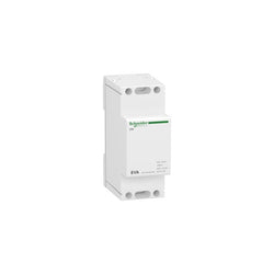
Acti 9 modular bell transfomer iTR - 230 V 50..60 Hz - output 8..12 V - 8 VA
Main
| Characteristic | Value(s) |
|---|---|
| Range | TeSys |
| Product or Component Type | Contactor |
| Device short name | LC1K |
| Device Application | Control |
| Contactor application | Motor control |
Complementary
| Characteristic | Value(s) |
|---|---|
| Utilisation category | AC-3 AC-3e AC-4 |
| Poles description | 3P |
| power pole contact composition | 3 NO |
| [Ue] rated operational voltage | Power circuit <= 690 V AC <= 400 Hz Signalling circuit <= 690 V AC <= 400 Hz |
| [Ie] rated operational current | 6 A (at <140 °F (60 °C)) at <= 440 V AC AC-3 for power circuit 6 A (at <140 °F (60 °C)) at <= 440 V AC AC-3e for power circuit |
| Control circuit type | AC 50/60 Hz |
| [Uc] control circuit voltage | 400 V AC 50/60 Hz |
| Motor power kW | 1.5 kW 220...230 V AC 50/60 Hz AC-3 2.2 kW 380...415 V AC 50/60 Hz AC-3 3 kW 440/690 V AC 50/60 Hz AC-3 1.5 kW 220...230 V AC 50/60 Hz AC-3e 2.2 kW 380...415 V AC 50/60 Hz AC-3e 3 kW 440/690 V AC 50/60 Hz AC-3e 1.5 kW 220...230 V AC 50/60 Hz AC-4 2.2 kW 380...415 V AC 50/60 Hz AC-4 3 kW 440/690 V AC 50/60 Hz AC-4 |
| Auxiliary contact composition | 1 NO |
| [Uimp] rated impulse withstand voltage | 8 kV |
| Overvoltage category | III |
| [Ith] conventional free air thermal current | 20 A (at 140 °F (60 °C)) for power circuit 10 A (at 122 °F (50 °C)) for signalling circuit |
| Irms rated making capacity | 110 A AC for power circuit conforming to IEC 60947 110 A AC for signalling circuit conforming to IEC 60947 |
| Rated breaking capacity | 110 A at 220...230 V conforming to IEC 60947 110 A at 380...400 V conforming to IEC 60947 110 A at 415 V conforming to IEC 60947 110 A at 440 V conforming to IEC 60947 80 A at 500 V conforming to IEC 60947 70 A at 660...690 V conforming to IEC 60947 |
| [Icw] rated short-time withstand current | 90 A 122 °F (50 °C) - 1 s for power circuit 85 A 122 °F (50 °C) - 5 s for power circuit 80 A 122 °F (50 °C) - 10 s for power circuit 60 A 122 °F (50 °C) - 30 s for power circuit 45 A 122 °F (50 °C) - 1 min for power circuit 40 A 122 °F (50 °C) - 3 min for power circuit 20 A 122 °F (50 °C) - >= 15 min for power circuit 80 A - 1 s for signalling circuit 90 A - 500 ms for signalling circuit 110 A - 100 ms for signalling circuit |
| Associated fuse rating | 25 A gG at <= 440 V for power circuit 25 A aM for power circuit 10 A gG for signalling circuit conforming to IEC 60947 10 A gG for signalling circuit conforming to VDE 0660 |
| Average impedance | 3 mOhm - Ith 20 A 50 Hz for power circuit |
| [Ui] rated insulation voltage | Power circuit 600 V UL 508 Power circuit 690 V IEC 60947-4-1 Signalling circuit 690 V IEC 60947-4-1 Signalling circuit 690 V IEC 60947-5-1 Signalling circuit 600 V UL 508 Power circuit 600 V CSA C22.2 No 14 Signalling circuit 600 V CSA C22.2 No 14 |
| Insulation resistance | > 10 MOhm for signalling circuit |
| Inrush power in VA | 30 VA (at 68 °F (20 °C)) |
| Hold-in power consumption in VA | 4.5 VA (at 68 °F (20 °C)) |
| Heat dissipation | 1.3 W |
| Control circuit voltage limits | Operational: 0.8...1.15 Uc (at <122 °F (50 °C)) Drop-out: >= 0.20 Uc (at <122 °F (50 °C)) |
| Connections - terminals | screw clamp terminals 1 0.002â¦0.006 in² (1.5â¦4 mm²)solid screw clamp terminals 1 0.001â¦0.006 in² (0.75â¦4 mm²)flexible without cable end screw clamp terminals 1 0.0005â¦0.004 in² (0.34â¦2.5 mm²)flexible with cable end screw clamp terminals 2 0.002â¦0.006 in² (1.5â¦4 mm²)solid screw clamp terminals 2 0.001â¦0.006 in² (0.75â¦4 mm²)flexible without cable end screw clamp terminals 2 0.0005â¦0.002 in² (0.34â¦1.5 mm²)flexible with cable end |
| Maximum operating rate | 3600 cyc/h |
| Auxiliary contacts type | Instantaneous 1 NO |
| Signalling circuit frequency | <= 400 Hz |
| Minimum switching current | 5 mA for signalling circuit |
| Minimum switching voltage | 17 V for signalling circuit |
| Mounting Support | Rail Plate |
| Tightening torque | 7.08â¦11.5 lbf.in (0.8â¦1.3 N.m) screw clamp terminals Philips No 2 7.08â¦11.5 lbf.in (0.8â¦1.3 N.m) screw clamp terminals flat à 6 mm 7.08â¦11.5 lbf.in (0.8â¦1.3 N.m) screw clamp terminals pozidriv No 2 |
| Operating time | 10...20 ms coil de-energisation and NO opening 10...20 ms coil energisation and NO closing |
| Safety reliability level | B10d = 1369863 cycles contactor with nominal load EN/ISO 13849-1 B10d = 20000000 cycles contactor with mechanical load EN/ISO 13849-1 |
| Non overlap distance | 0.02 in (0.5 mm) |
| Mechanical durability | 10 Mcycles |
| Electrical durability | 1.3 Mcycles 6 A AC-3 <= 440 V 1.3 Mcycles 6 A AC-3e <= 440 V 0.05 Mcycles 36 A AC-4 <= 440 V |
| Mechanical robustness | Shocks contactor closed, on X axis10 Gn for 11 ms IEC 60068-2-27 Shocks contactor closed, on Y axis15 Gn for 11 ms IEC 60068-2-27 Shocks contactor closed, on Z axis15 Gn for 11 ms IEC 60068-2-27 Shocks contactor opened, on X axis6 Gn for 11 ms IEC 60068-2-27 Shocks contactor opened, on Y axis10 Gn for 11 ms IEC 60068-2-27 Shocks contactor opened, on Z axis10 Gn for 11 ms IEC 60068-2-27 Vibrations contactor closed4 Gn, 5...300 Hz IEC 60068-2-6 Vibrations contactor opened2 Gn, 5...300 Hz IEC 60068-2-6 |
| Height | 2.3 in (58 mm) |
| Width | 1.8 in (45 mm) |
| Depth | 2.2 in (57 mm) |
| Product Weight | 0.40 lb(US) (0.18 kg) |

Main
| Characteristic | Value(s) |
|---|---|
| Range | TeSys |
| Range of Product | TeSys Deca |
| Product or Component Type | Contactor |
| Device short name | LC1D |
| Contactor application | Resistive load Resistive load |
| Utilisation category | AC-1 AC-2 AC-3 AC-3e AC-4 |
| Poles description | 3P |
| [Ue] rated operational voltage | Power circuit <= 690 V AC 25...400 Hz |
| [Ie] rated operational current | 80 A (at <140 °F (60 °C)) at <= 440 V AC AC-1 for power circuit 50 A (at <140 °F (60 °C)) at <= 440 V AC AC-3e for power circuit 50 A (at <140 °F (60 °C)) at <= 440 V AC AC-3 for power circuit |
| [Uc] control circuit voltage | 48 V DC |
Complementary
| Characteristic | Value(s) |
|---|---|
| Motor power kW | 25 kW at 415 V AC 50 Hz (AC-3) 30 kW at 440 V AC 50 Hz (AC-3) 30 kW at 500 V AC 50 Hz (AC-3) 33 kW at 660...690 V AC 50 Hz (AC-3) 15 kW at 220...230 V AC 50 Hz (AC-3) 11 kW at 400 V AC 50 Hz (AC-4) 30 kW at 1000 V AC 50 Hz (AC-3) 22 kW at 380...400 V AC 50 Hz (AC-3e) 25 kW at 415 V AC 50 Hz (AC-3e) 30 kW at 440 V AC 50 Hz (AC-3e) 30 kW at 500 V AC 50 Hz (AC-3e) 33 kW at 660...690 V AC 50 Hz (AC-3e) 15 kW at 220...230 V AC 50 Hz (AC-3e) 30 kW at 1000 V AC 50 Hz (AC-3e) 25 kW at 415 V AC 50 Hz 22 kW at 380...400 V AC 50 Hz |
| Maximum Horse Power Rating | 7.5 hp at 230/240 V AC 60 Hz for 1 phase motors 15 hp at 200/208 V AC 60 Hz for 3 phase motors 15 hp at 230/240 V AC 60 Hz for 3 phase motors 40 hp at 460/480 V AC 60 Hz for 3 phase motors 40 hp at 575/600 V AC 60 Hz for 3 phase motors 3 hp at 115 V AC 60 Hz for 1 phase motors |
| Compatibility code | LC1D |
| Pole contact composition | 3 NO |
| Protective cover | With |
| [Ith] conventional free air thermal current | 80 A (at 140 °F (60 °C)) for power circuit 10 A (at 140 °F (60 °C)) for control circuit |
| Irms rated making capacity | 900 A at 440 V DC for power circuit conforming to IEC 60947 900 A at 440 V for power circuit conforming to IEC 60947 250 A DC for control circuit conforming to IEC 60947-5-1 |
| Rated breaking capacity | 900 A at 440 V for power circuit conforming to IEC 60947 |
| Associated fuse rating | 100 A gG at <= 690 V coordination type 1 for power circuit 100 A gG at <= 690 V coordination type 2 for power circuit conforming to IEC 60947-5-1 10 A gG for control circuit conforming to IEC 60947-5-1 |
| Power dissipation per pole | 9.6 W AC-1 3.7 W AC-3e 3.7 W AC-3 |
| [Ui] rated insulation voltage | Control circuit 600 V UL Power circuit 600 V CSA Power circuit 600 V UL IEC 60947-1 Control circuit 690 V IEC 60947-1 Power circuit 690 V CSA IEC 60947-1 Control circuit 600 V CSA |
| Overvoltage category | III |
| [Uimp] rated impulse withstand voltage | 8 kV IEC 60947 |
| Safety reliability level | B10d = 20000000 cycles contactor with mechanical load EN/ISO 13849-1 B10d = 1369863 cycles contactor with nominal load EN/ISO 13849-1 |
| Mechanical durability | 10000000 cycles |
| Control circuit type | DC wide range |
| Coil technology | Built-in bidirectional peak limiting diode suppressor |
| Control circuit voltage limits | 0.75...1.25 Uc (-40â¦140 °F (-40â¦60 °C)):operational DC 1...1.25 Uc (140â¦158 °F (60â¦70 °C)):operational DC 0.1...0.3 Uc (-40â¦158 °F (-40â¦70 °C)):drop-out DC |
| Inrush power in W | 19 W 68 °F (20 °C)) |
| Hold-in power consumption in W | 7.4 W 68 °F (20 °C) |
| Rated operational power in W | 38 W 48 V DC-13 3000000 cycles - control circuit 76 W 48 V DC-13 1000000 cycles - control circuit 12 W 48 V DC-13 10000000 cycles - control circuit |
| Operating time | 50 ±15 % ms closing 20 ±20 % ms opening |
| Time constant | 34 ms |
| Maximum operating rate | 3600 cyc/h at 60 °C |
| Connections - terminals | Control circuit: screw clamp terminals 2 0.002â¦0.006 in² (1â¦4 mm²) - cable stiffness: rigid without cable end Control circuit: screw clamp terminals 1 0.002â¦0.006 in² (1â¦4 mm²) - cable stiffness: flexible without cable end Control circuit: screw clamp terminals 2 0.002â¦0.006 in² (1â¦4 mm²) - cable stiffness: flexible without cable end Control circuit: screw clamp terminals 1 0.002â¦0.004 in² (1â¦2.5 mm²) - cable stiffness: flexible with cable end Control circuit: screw clamp terminals 2 0.002â¦0.004 in² (1â¦2.5 mm²) - cable stiffness: flexible with cable end Power circuit: screw terminals 1 0.004â¦0.04 in² (2.5â¦25 mm²) - cable stiffness: rigid Power circuit: screw terminals 2 0.004â¦0.02 in² (2.5â¦16 mm²) - cable stiffness: rigid without cable end Power circuit: screw terminals 1 0.004â¦0.04 in² (2.5â¦25 mm²) - cable stiffness: flexible without cable end Power circuit: screw terminals 2 0.004â¦0.02 in² (2.5â¦16 mm²) - cable stiffness: flexible without cable end Power circuit: screw terminals 1 0.004â¦0.04 in² (2.5â¦25 mm²) - cable stiffness: flexible with cable end Power circuit: screw terminals 2 0.004â¦0.02 in² (2.5â¦10 mm²) - cable stiffness: flexible with cable end Control circuit: screw clamp terminals 2 0.002â¦0.006 in² (1â¦4 mm²) - cable stiffness: rigid Control circuit: screw clamp terminals 1 0.002â¦0.006 in² (1â¦4 mm²) - cable stiffness: rigid |
| Tightening torque | Control circuit 15.05 lbf.in (1.7 N.m) screw clamp terminal Philips No 2 Power circuit 44.3 lbf.in (5 N.m) screw terminal flat à 6 to à 8 mm Control circuit 15.05 lbf.in (1.7 N.m) screw clamp terminal pozidriv No 2 Control circuit 15.05 lbf.in (1.7 N.m) screw clamp terminal flat à 6 mm |
| Auxiliary contact composition | 1 NO + 1 NC |
| Auxiliary contacts type | Mirror contact 1 NC IEC 60947-4-1 Mechanically linked 1 NO + 1 NC IEC 60947-5-1 |
| Minimum switching voltage | 17 V for control circuit |
| Minimum switching current | 5 mA for control circuit |
| Insulation resistance | > 10 MOhm for control circuit |
| Non-overlap time | 1.5 ms on energisation between NC and NO contacts 1.5 ms on de-energisation between NC and NO contacts |
| Mounting Support | Rail Plate |
Vigi C120 - earth leakage add-on block - 4P - 30 mA - class AC

TeSys F contactor, 3 poles (3NO), 150A/690V AC-3, for motor applications up to 75kW@400V. It provides a 220V 50Hz AC coil, bolt terminals for bars or cables with lugs. For high operating rates until 2400 cycles/hour and environments until 55°C, it procures high reliability and durability. It makes installation and maintenance easy thanks to its drawer-mounted coil and a large choice of add-on blocks and accessories (to be ordered separately). Multi standards certified (IEC, UL, CSA, CCC, EAC, Marine), Green Premium compliant (RoHS/REACh).
Main
| Characteristic | Value(s) |
|---|---|
| Range | TeSys |
| Range of Product | TeSys F |
| Product or Component Type | Contactor |
| Device short name | LC1F |
| Contactor application | Motor control Resistive load |
| Utilisation category | AC-3 AC-4 AC-1 |
| Poles description | 3P |
| [Ue] rated operational voltage | <= 690 V AC 50/60 Hz <= 460 V DC |
| [Uc] control circuit voltage | 220 V AC 50 Hz |
| [Ie] rated operational current | 250 A (at <104 °F (40 °C)) at <= 440 V AC-1 150 A (at <131 °F (55 °C)) at <= 440 V AC-3 |
Complementary
| Characteristic | Value(s) |
|---|---|
| [Uimp] rated impulse withstand voltage | 8 kV |
| [Ith] conventional free air thermal current | 250 A (at 104 °F (40 °C)) |
| Rated breaking capacity | 1200 A conforming to IEC 60947-4-1 |
| [Icw] rated short-time withstand current | 1200 A 104 °F (40 °C) - 10 s 700 A 104 °F (40 °C) - 30 s 600 A 104 °F (40 °C) - 1 min 450 A 104 °F (40 °C) - 3 min 350 A 104 °F (40 °C) - 10 min |
| Associated fuse rating | 160 A aM at <= 440 V 250 A gG at <= 440 V |
| Average impedance | 0.35 mOhm - Ith 250 A 50 Hz |
| [Ui] rated insulation voltage | 1000 V IEC 60947-4-1 1500 V VDE 0110 group C |
| Power dissipation per pole | 22 W AC-1 8 W AC-3 |
| Overvoltage category | III |
| power pole contact composition | 3 NO |
| Motor power kW | 75 kW at 380...400 V AC 50/60 Hz (AC-3) 80 kW at 415 V AC 50/60 Hz (AC-3) 80 kW at 440 V AC 50/60 Hz (AC-3) 90 kW at 500 V AC 50/60 Hz (AC-3) 100 kW at 660...690 V AC 50/60 Hz (AC-3) 40 kW at 220...230 V AC 50/60 Hz (AC-3) 22 kW at 400 V AC 50/60 Hz (AC-4) |
| Control circuit voltage limits | Operational 0.85...1.1 Uc 50/60 Hz 131 °F (55 °C)) Drop-out 0.35...0.55 Uc 50/60 Hz 131 °F (55 °C)) |
| Mechanical durability | 10 Mcycles |
| Inrush power in VA | 550 VA, 50 Hz 0.3 68 °F (20 °C)) |
| Hold-in power consumption in VA | 45 VA, 50 Hz 0.3 68 °F (20 °C)) |
| Maximum operating rate | 2400 cyc/h 131 °F (55 °C) |
| Operating time | 23...35 ms closing 5...15 ms opening |
| Connections - terminals | Control circuit screw clamp terminals 1 0.002â¦0.006 in² (1â¦4 mm²)flexible without cable end Control circuit screw clamp terminals 2 0.002â¦0.006 in² (1â¦4 mm²)flexible without cable end Control circuit screw clamp terminals 1 0.002â¦0.006 in² (1â¦4 mm²)flexible with cable end Control circuit screw clamp terminals 2 0.002â¦0.004 in² (1â¦2.5 mm²)flexible with cable end Control circuit screw clamp terminals 1 0.002â¦0.006 in² (1â¦4 mm²)solid without cable end Control circuit screw clamp terminals 2 0.002â¦0.006 in² (1â¦4 mm²)solid without cable end Power circuit bar 2 25 x 3 mm Power circuit lugs-ring terminals 1 0.2 in² (120 mm²) Power circuit connector 1 0.2 in² (120 mm²) Power circuit bolted connection |
| Tightening torque | Control circuit 10.6 lbf.in (1.2 N.m) Power circuit 159.3 lbf.in (18 N.m) |
| Mounting Support | Plate |
| Heat dissipation | 12â¦16 W |
| Standards | EN 60947-4-1 IEC 60947-1 JIS C8201-4-1 IEC 60947-4-1 EN 60947-1 |
| Product Certifications | LROS (Lloyds register of shipping) RINA BV RMRoS UL CB DNV ABS CCC |
| Compatibility code | LC1F |
| Control circuit type | AC 50 Hz |