
 1 year warranty

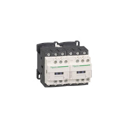
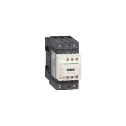
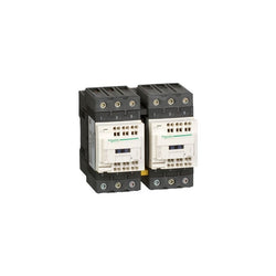
TeSys D reversing contactor - 3P(3 NO) - AC-3 - <= 440 V 18 A - 230 V AC coil

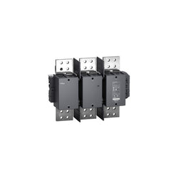
TeSys F contactor - 3P (3 NO) - AC-1 - <= 440 V 1400 A - coil 230 V AC

MX Shunt Trip MX plus 1 OF 48-130Vac dc
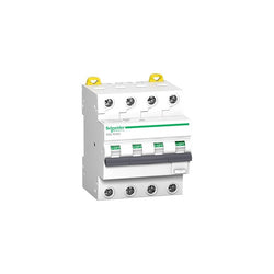
Acti9 iC60 RCBO - 4P - 32 A - B Curve - 6000A/6kA - 30 mA - SI type
Main
| Characteristic | Value(s) |
|---|---|
| Range | TeSys |
| Product or component type | Contactor |
| Device short name | LC1K |
| Device application | Control |
| Contactor application | Motor control Resistive load |
Complementary
| Characteristic | Value(s) |
|---|---|
| Utilisation category | AC-3 AC-3e AC-1 AC-4 |
| Poles description | 3P |
| power pole contact composition | 3 NO |
| [Ue] rated operational voltage | Power circuit: <= 690 V AC <= 400 Hz Signalling circuit: <= 690 V AC <= 400 Hz |
| [Ie] rated operational current | 9 A (at <60 °C) at <= 440 V AC AC-3 for power circuit 9 A (at <60 °C) at <= 440 V AC AC-3e for power circuit 20 A (at <60 °C) at <= 690 V AC AC-1 for power circuit |
| Control circuit type | AC at 50/60 Hz |
| [Uc] control circuit voltage | 100 V AC 50/60 Hz |
| Motor power kW | 2.2 kW at 220...230 V AC 50/60 Hz AC-3 4 kW at 380...415 V AC 50/60 Hz AC-3 4 kW at 440/690 V AC 50/60 Hz AC-3 2.2 kW at 220...230 V AC 50/60 Hz AC-3e 4 kW at 380...415 V AC 50/60 Hz AC-3e 4 kW at 440/690 V AC 50/60 Hz AC-3e 2.2 kW at 220...230 V AC 50/60 Hz AC-4 4 kW at 380...415 V AC 50/60 Hz AC-4 4 kW at 440/690 V AC 50/60 Hz AC-4 |
| Auxiliary contact composition | 1 NC |
| [Uimp] rated impulse withstand voltage | 8 kV |
| Overvoltage category | III |
| [Ith] conventional free air thermal current | 20 A (at 60 °C) for power circuit 10 A (at 50 °C) for signalling circuit |
| Irms rated making capacity | 110 A AC for power circuit conforming to IEC 60947 110 A AC for signalling circuit conforming to IEC 60947 |
| Rated breaking capacity | 110 A at 220...230 V conforming to IEC 60947 110 A at 380...400 V conforming to IEC 60947 110 A at 415 V conforming to IEC 60947 110 A at 440 V conforming to IEC 60947 80 A at 500 V conforming to IEC 60947 70 A at 660...690 V conforming to IEC 60947 |
| [Icw] rated short-time withstand current | 90 A 50 °C - 1 s for power circuit 85 A 50 °C - 5 s for power circuit 80 A 50 °C - 10 s for power circuit 60 A 50 °C - 30 s for power circuit 45 A 50 °C - 1 min for power circuit 40 A 50 °C - 3 min for power circuit 20 A 50 °C - >= 15 min for power circuit 80 A - 1 s for signalling circuit 90 A - 500 ms for signalling circuit 110 A - 100 ms for signalling circuit |
| Associated fuse rating | 25 A gG at <= 440 V for power circuit 25 A aM for power circuit 10 A gG for signalling circuit conforming to IEC 60947 10 A gG for signalling circuit conforming to VDE 0660 |
| Average impedance | 3 mOhm - Ith 20 A 50 Hz for power circuit |
| Insulation resistance | > 10 MOhm for signalling circuit |
| Inrush power in VA | 30 VA (at 20 °C) |
| Hold-in power consumption in VA | 4.5 VA (at 20 °C) |
| Heat dissipation | 1.3 W |
| Control circuit voltage limits | Operational: 0.8...1.15 Uc (at <50 °C) Drop-out: >= 0.20 Uc (at <50 °C) |
| Connections - terminals | Screw clamp terminals 1 cable(s) 1.5â¦4 mm²solid Screw clamp terminals 1 cable(s) 0.75â¦4 mm²flexible without cable end Screw clamp terminals 1 cable(s) 0.34â¦2.5 mm²flexible with cable end Screw clamp terminals 2 cable(s) 1.5â¦4 mm²solid Screw clamp terminals 2 cable(s) 0.75â¦4 mm²flexible without cable end Screw clamp terminals 2 cable(s) 0.34â¦1.5 mm²flexible with cable end |
| Maximum operating rate | 3600 cyc/h |
| Auxiliary contacts type | type instantaneous 1 NC |
| Signalling circuit frequency | <= 400 Hz |
| Minimum switching current | 5 mA for signalling circuit |
| Minimum switching voltage | 17 V for signalling circuit |
| Operating time | 10...20 ms coil de-energisation and NO opening 10...20 ms coil energisation and NO closing |
| Safety reliability level | B10d = 1369863 cycles contactor with nominal load conforming to EN/ISO 13849-1 B10d = 20000000 cycles contactor with mechanical load conforming to EN/ISO 13849-1 |
| Non overlap distance | 0.5 mm |
| Mechanical durability | 10 Mcycles |
| Electrical durability | 1.3 Mcycles 9 A AC-3 at Ue <= 440 V 1.3 Mcycles 9 A AC-3e at Ue <= 440 V 0.16 Mcycles 20 A AC-1 at Ue <= 690 V 0.02 Mcycles 54 A AC-4 at Ue <= 440 V |
| Mechanical robustness | Shocks contactor closed, on X axis: 10 Gn for 11 ms conforming to IEC 60068-2-27 Shocks contactor closed, on Y axis: 15 Gn for 11 ms conforming to IEC 60068-2-27 Shocks contactor closed, on Z axis: 15 Gn for 11 ms conforming to IEC 60068-2-27 Shocks contactor opened, on X axis: 6 Gn for 11 ms conforming to IEC 60068-2-27 Shocks contactor opened, on Y axis: 10 Gn for 11 ms conforming to IEC 60068-2-27 Shocks contactor opened, on Z axis: 10 Gn for 11 ms conforming to IEC 60068-2-27 Vibrations contactor closed: 4 Gn, 5...300 Hz conforming to IEC 60068-2-6 Vibrations contactor opened: 2 Gn, 5...300 Hz conforming to IEC 60068-2-6 |
| Height | 58 mm |
| Width | 45 mm |
| Depth | 57 mm |
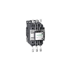
TeSys Deca contactor, 3 poles (3NO), for switching 3-phase capacitor banks up to 63kVAR@400V 50Hz (104kVAR@690V). It provides a 24V 50/60Hz AC coil, 1NO+2NC instantaneous auxiliary contacts, with front mounted early make poles and pre-wired damping resistors for current limitation. For operating rates until 240 cycles/hour and environments until 60°C, it procures high reliability and durability. Compact (85mm width), DIN-rail mounting or screw fixing. Multi standards certified (IEC, UL, CSA) and compliant with shunt capacitors standard IEC 60831.
Main
| Characteristic | Value(s) |
|---|---|
| Range | TeSys |
| product name | TeSys LC1D.K TeSys Deca |
| Product or Component Type | Capacitor duty contactor |
| Device short name | LC1DWK |
| Device Application | Control |
| Contactor application | Power factor correction |
| Utilisation category | AC-6b |
| Poles description | 3P |
| power pole contact composition | 3 NO |
| Device location in system | Line interruption Inside delta interruption |
| [Ue] rated operational voltage | Power circuit 690 V AC 50/60 Hz |
| Reactive power rating | 35 kvar 230 V AC 50 Hz 140 °F (60 °C) 63 kvar 400 V AC 50 Hz 140 °F (60 °C) 67 kvar 440 V AC 50 Hz 140 °F (60 °C) 104 kvar 690 V AC 50 Hz 140 °F (60 °C) 30 kvar 230 V AC 60 Hz 140 °F (60 °C) 60 kvar 460 V AC 60 Hz 140 °F (60 °C) 80 kvar 575 V AC 60 Hz 140 °F (60 °C) |
| Control circuit type | AC 50/60 Hz |
| [Uc] control circuit voltage | 24 V AC 50/60 Hz |
| Auxiliary contact composition | 1 NO + 2 NC instantaneous |
| Electrical durability | 300000 cycles 400 V 200000 cycles 690 V |
| Mounting Support | DIN rail Plate |
| Standards | EN/IEC 60947-1 EN/IEC 60947-4-1 UL 60947-4-1 CSA C22.2 No 60947-4-1 |
| Product Certifications | IECEE CB Scheme UL CSA UKCA |
| Connections - terminals | Control circuit: screw clamp terminals 1 0.002â¦0.006 in² (1â¦4 mm²) - cable stiffness: solid Control circuit: screw clamp terminals 2 0.002â¦0.006 in² (1â¦4 mm²) - cable stiffness: solid Control circuit: screw clamp terminals 1 0.002â¦0.006 in² (1â¦4 mm²) - cable stiffness: flexible without cable end Control circuit: screw clamp terminals 2 0.002â¦0.006 in² (1â¦4 mm²) - cable stiffness: flexible without cable end Control circuit: screw clamp terminals 1 0.002â¦0.006 in² (1â¦4 mm²) - cable stiffness: flexible with cable end Control circuit: screw clamp terminals 2 0.002â¦0.004 in² (1â¦2.5 mm²) - cable stiffness: flexible with cable end Power circuit: connector 1 0.006â¦0.08 in² (4â¦50 mm²) - cable stiffness: solid Power circuit: connector 2 0.006â¦0.04 in² (4â¦25 mm²) - cable stiffness: solid Power circuit: connector 1 0.006â¦0.08 in² (4â¦50 mm²) - cable stiffness: flexible without cable end Power circuit: connector 2 0.006â¦0.04 in² (4â¦25 mm²) - cable stiffness: flexible without cable end Power circuit: connector 1 0.006â¦0.08 in² (4â¦50 mm²) - cable stiffness: flexible with cable end Power circuit: connector 2 0.006â¦0.02 in² (4â¦16 mm²) - cable stiffness: flexible with cable end |
| Tightening torque | Power circuit 79.7 lbf.in (9 N.m) connector Control circuit 15.05 lbf.in (1.7 N.m) screw clamp terminals |
| Maximum operating rate | 100 cyc/h |
Complementary
| Characteristic | Value(s) |
|---|---|
| Auxiliary contacts type | Mechanically linked 1 NO + 2 NC IEC 60947-5-1 |
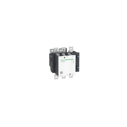
TeSys F contactor - 3P (3 NO) - AC-3 - <= 440 V 275 A - coil 230 V AC. Comes without coil.
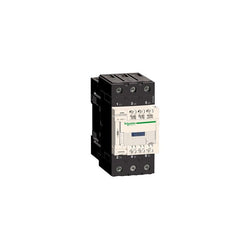
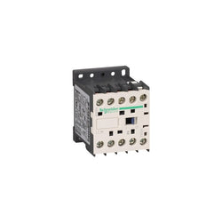
TeSys D contactor - 3P(3 NO) - AC-3 - <= 440 V 65 A - 24 V AC 50/60 Hz coil
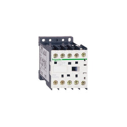
TeSys Deca contactor, 3 poles (3NO), for motor control applications up to 40A/440V AC-3/3e (18.5kW@400V). It provides a 100V 60Hz AC coil, 1NO+1NC built-in auxiliary contacts (NC mirror certified), power connection by EverLink BTR screw connectors, control connection by screw clamp terminals. For operating rates until 3600 cycles/hour and environments until 60°C, it procures high reliability and durability. Compact (55mm width), DIN-rail mounting or screw fixing. Multi standards certified (IEC, UL, CSA, CCC, EAC, Marine), Green Premium compliant (RoHS/REACh).
Main
| Characteristic | Value(s) |
|---|---|
| Range | TeSys TeSys Deca |
| Range of Product | TeSys Deca |
| Product or Component Type | Contactor |
| Device short name | LC1D |
| Contactor application | Resistive load Motor control |
| Utilisation category | AC-4 AC-1 AC-3 AC-3e |
| Poles description | 3P |
| [Ue] rated operational voltage | Power circuit <= 690 V AC 25...400 Hz Power circuit <= 300 V DC |
| [Ie] rated operational current | 60 A (at <140 °F (60 °C)) at <= 440 V AC AC-1 for power circuit 40 A (at <140 °F (60 °C)) at <= 440 V AC AC-3 for power circuit 40 A (at <140 °F (60 °C)) at <= 440 V AC AC-3e for power circuit |
| [Uc] control circuit voltage | 100 V AC 50/60 Hz |
Complementary
| Characteristic | Value(s) |
|---|---|
| Motor power kW | 18.5 kW at 380...400 V AC 50/60 Hz (AC-3) 11 kW at 220...230 V AC 50/60 Hz (AC-3) 22 kW at 415...440 V AC 50/60 Hz (AC-3) 22 kW at 500 V AC 50/60 Hz (AC-3) 30 kW at 660...690 V AC 50/60 Hz (AC-3) 9 kW at 400 V AC 50/60 Hz (AC-4) 18.5 kW at 380...400 V AC 50/60 Hz (AC-3e) 11 kW at 220...230 V AC 50/60 Hz (AC-3e) 22 kW at 415...440 V AC 50/60 Hz (AC-3e) 22 kW at 500 V AC 50/60 Hz (AC-3e) 30 kW at 660...690 V AC 50/60 Hz (AC-3e) |
| Maximum Horse Power Rating | 5 hp at 230/240 V AC 50/60 Hz for 1 phase motors 10 hp at 230/240 V AC 50/60 Hz for 3 phase motors 30 hp at 575/600 V AC 50/60 Hz for 3 phase motors 10 hp at 200/208 V AC 50/60 Hz for 3 phase motors 3 hp at 115 V AC 50/60 Hz for 1 phase motors 30 hp at 460/480 V AC 50/60 Hz for 3 phase motors |
| Compatibility code | LC1D |
| Pole contact composition | 3 NO |
| Protective cover | With |
| [Ith] conventional free air thermal current | 10 A (at 140 °F (60 °C)) for signalling circuit 60 A (at 140 °F (60 °C)) for power circuit |
| Irms rated making capacity | 140 A AC for signalling circuit conforming to IEC 60947-5-1 250 A DC for signalling circuit conforming to IEC 60947-5-1 800 A at 440 V for power circuit conforming to IEC 60947 |
| Rated breaking capacity | 800 A at 440 V for power circuit conforming to IEC 60947 |
| [Icw] rated short-time withstand current | 320 A 104 °F (40 °C) - 10 s for power circuit 720 A 104 °F (40 °C) - 1 s for power circuit 72 A 104 °F (40 °C) - 10 min for power circuit 165 A 104 °F (40 °C) - 1 min for power circuit 100 A - 1 s for signalling circuit 120 A - 500 ms for signalling circuit 140 A - 100 ms for signalling circuit |
| Associated fuse rating | 10 A gG for signalling circuit conforming to IEC 60947-5-1 80 A gG at <= 690 V coordination type 1 for power circuit 80 A gG at <= 690 V coordination type 2 for power circuit |
| Average impedance | 1.5 mOhm - Ith 60 A 50 Hz for power circuit |
| Power dissipation per pole | 2.4 W AC-3 5.4 W AC-1 2.4 W AC-3e |
| [Ui] rated insulation voltage | Power circuit 600 V CSA Power circuit 600 V UL Signalling circuit 690 V IEC 60947-1 Signalling circuit 600 V CSA Signalling circuit 600 V UL Power circuit 690 V IEC 60947-4-1 |
| Overvoltage category | III |
| pollution degree | 3 |
| [Uimp] rated impulse withstand voltage | 6 kV IEC 60947 |
| Safety reliability level | B10d = 1369863 cycles contactor with nominal load EN/ISO 13849-1 B10d = 20000000 cycles contactor with mechanical load EN/ISO 13849-1 |
| Mechanical durability | 6 Mcycles |
| Electrical durability | 1.4 Mcycles 60 A AC-1 <= 440 V 1.5 Mcycles 40 A AC-3 <= 440 V 1.5 Mcycles 40 A AC-3e <= 440 V |
| Control circuit type | AC 50/60 Hz |
| Coil technology | Without built-in suppressor module |
| Control circuit voltage limits | 0.3...0.6 Uc (-40â¦158 °F (-40â¦70 °C)):drop-out AC 50/60 Hz 0.8...1.1 Uc (-40â¦140 °F (-40â¦60 °C)):operational AC 50 Hz 0.85...1.1 Uc (-40â¦140 °F (-40â¦60 °C)):operational AC 60 Hz 1...1.1 Uc (140â¦158 °F (60â¦70 °C)):operational AC 50/60 Hz |
| Inrush power in VA | 140 VA 60 Hz cos phi 0.75 (at 68 °F (20 °C)) 160 VA 50 Hz cos phi 0.75 (at 68 °F (20 °C)) |
| Hold-in power consumption in VA | 13 VA 60 Hz cos phi 0.3 (at 68 °F (20 °C)) 15 VA 50 Hz cos phi 0.3 (at 68 °F (20 °C)) |
| Heat dissipation | 4â¦5 W at 50/60 Hz |
| Operating time | 4...19 ms opening 12...26 ms closing |
| Maximum operating rate | 3600 cyc/h at 60 °C |
| Connections - terminals | Control circuit: screw clamp terminals 2 0.002â¦0.004 in² (1â¦2.5 mm²) - cable stiffness: flexible with cable end Control circuit: screw clamp terminals 1 0.002â¦0.006 in² (1â¦4 mm²) - cable stiffness: flexible without cable end Control circuit: screw clamp terminals 2 0.002â¦0.006 in² (1â¦4 mm²) - cable stiffness: flexible without cable end Control circuit: screw clamp terminals 1 0.002â¦0.006 in² (1â¦4 mm²) - cable stiffness: flexible with cable end Control circuit: screw clamp terminals 1 0.002â¦0.006 in² (1â¦4 mm²) - cable stiffness: solid without cable end Control circuit: screw clamp terminals 2 0.002â¦0.006 in² (1â¦4 mm²) - cable stiffness: solid without cable end Power circuit: EverLink BTR screw connectors 1 0.002â¦0.05 in² (1â¦35 mm²) - cable stiffness: flexible without cable end Power circuit: EverLink BTR screw connectors 2 0.002â¦0.04 in² (1â¦25 mm²) - cable stiffness: flexible without cable end Power circuit: EverLink BTR screw connectors 1 0.002â¦0.05 in² (1â¦35 mm²) - cable stiffness: flexible with cable end Power circuit: EverLink BTR screw connectors 2 0.002â¦0.04 in² (1â¦25 mm²) - cable stiffness: flexible with cable end Power circuit: EverLink BTR screw connectors 1 0.002â¦0.05 in² (1â¦35 mm²) - cable stiffness: solid without cable end Power circuit: EverLink BTR screw connectors 2 0.002â¦0.04 in² (1â¦25 mm²) - cable stiffness: solid without cable end |
| Tightening torque | Control circuit 15.05 lbf.in (1.7 N.m) screw clamp terminals flat à 6 mm Control circuit 15.05 lbf.in (1.7 N.m) screw clamp terminals Philips No 2 Power circuit 70.8 lbf.in (8 N.m) EverLink BTR screw connectors 0.04â¦0.05 in² (25â¦35 mm²) hexagonal 0.2 in (4 mm) Power circuit 44.3 lbf.in (5 N.m) EverLink BTR screw connectors 0.002â¦0.04 in² (1â¦25 mm²) hexagonal 0.2 in (4 mm) Control circuit 15.05 lbf.in (1.7 N.m) screw clamp terminals pozidriv No 2 Power circuit 22.1 lbf.in (2.5 N.m) screw clamp terminals pozidriv No 2 |
| Auxiliary contact composition | 1 NO + 1 NC |
| Auxiliary contacts type | Mechanically linked 1 NO + 1 NC IEC 60947-5-1 Mirror contact 1 NC IEC 60947-4-1 |
| Signalling circuit frequency | 25...400 Hz |
| Minimum switching voltage | 17 V for signalling circuit |
| Minimum switching current | 5 mA for signalling circuit |
| Insulation resistance | > 10 MOhm for signalling circuit |
| Non-overlap time | 1.5 ms on de-energisation between NC and NO contact 1.5 ms on energisation between NC and NO contact |
| Mounting Support | Rail Plate |

TeSys K contactor - 3P - AC-3 <= 440 V 12 A - 1 NC aux. - 24 V DC coil

PLC Direct is not an authorized distributor. We offer a broad range of in-stock products with minimal lead time.

TeSys Deca motor thermal magnetic circuit breaker GV2ME, push button (control), thermal outlet range: 2.5-4 A, screw clamp terminals
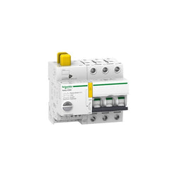
This Acti9 Reflex iC60N is a low voltage integrated control circuit breaker. It is a 3P circuit breaker with 3 protected poles, 25A rated current and C tripping curve. It can be mounted on DIN rail for modular installation. Its width is 11 modules of 9mm. As circuit breaker, its breaking capacity, according to IEC/EN 60947-2, is 20kA at 220VAC to 240VAC, and 10kA at 380VAC to 415VAC. As circui-breaker, it protects circuits against short circuit and overload currents, disconnection in the industrial sector. It can control a device remotely by latched and/or impulse-type order according to the 3 operating modes to be chosen by the user. It has an IP20 degree of protection (as per IEC/EN 60529) on its terminals. It becomes IP40 once in modular enclosure with insulation class II. Resetting after a fault is performed manually by the resetting handle. The Ti24 interface allows direct interfacing of the Reflex iC60 with a PLC. It allows to execute remote control, to indicate the state of the control circuit and circuit breaker state information, to connect it to the Acti9 Smartlink thanks to the prefabricated cables.
Main
| Characteristic | Value(s) |
|---|---|
| Device application | Distribution Control |
| Range | Acti9 |
| product name | Reflex iC60 |
| Device short name | Reflex iC60N |
| Product or component type | Integrated control circuit breaker |
| Poles description | 3P |
| Number of protected poles | 3 |
| Network type | AC |
| Trip unit technology | Thermal-magnetic |
| Curve code | C |
Complementary
| Characteristic | Value(s) |
|---|---|
| [In] rated current | 25 A |
| Network frequency | 50/60 Hz |
| Breaking capacity code | N |
| Breaking capacity | 20 kA Icu at 220...240 V AC 50/60 Hz conforming to EN/IEC 60947-2 10 kA Icu at 380...415 V AC 50/60 Hz conforming to EN/IEC 60947-2 |
| [Ui] rated insulation voltage | 500 V AC |
| Contact position indicator | Yes |
| control type | ON/OFF button Remote control by pulse Remote control by continuous command Toggle |
| Control signal type | Maintained Impulse Maintained very low voltage |
| Local signalling | Flashing LED: device overheat Green LED: device ON Flashing LED: device tripped Flashing LED: device ready Red LED: fault |
| [Uc] control circuit voltage | 230 V AC 50/60 Hz 24 V AC 50/60 Hz 48 V AC 50/60 Hz 24 V DC 48 V DC |
| [Us] rated supply voltage | 230 V AC at 50/60 Hz |
| Mounting mode | Fixed |
| Mounting support | 35 mm symmetrical DIN rail |
| 9 mm pitches | 11 |
| Height | 84 mm |
| Width | 99 mm |
| Depth | 77 mm |
| Colour | White |
| Mechanical durability | 50000 cycles |
| Electrical durability | AC-1: 50000 cycles AC 50 Hz |
| Provision for padlocking | Padlockable |
| Locking options description | Padlock in OFF position |
| Earth-leakage protection | Separate block |
| Product compatibility | With PLC |

Undervoltage release (MN), TeSys GV2-GV3, 500V AC 50Hz / 600V AC 60Hz


TeSys D contactor - 3P(3 NO) - AC-3 - <= 440 V 65 A - 36 V DC standard coil

Acti9 iC60 RCBO - 4P - 10 A - C Curve - 6000A/6kA - 30 mA - A type
TeSys K contactor - 3P - AC-3 <= 440 V 9 A - 1 NC aux. - 48 V AC coil
Main
| Characteristic | Value(s) |
|---|---|
| Range | TeSys |
| product name | TeSys Deca |
| Product or Component Type | Reversing contactor |
| Device short name | LC2D |
| Contactor application | Motor control Resistive load |
| Utilisation category | AC-1 AC-3 |
| Device presentation | Preassembled with reversing power busbar |
| Poles description | 3P |
| power pole contact composition | 3 NO |
| [Ue] rated operational voltage | Power circuit <= 690 V AC 25...400 Hz Power circuit <= 300 V DC |
| [Ie] rated operational current | 50 A (at <140 °F (60 °C)) at <= 440 V AC AC-3 for power circuit 80 A (at <140 °F (60 °C)) at <= 440 V AC AC-1 for power circuit |
| Motor power kW | 15 kW at 220...230 V AC 50 Hz 22 kW at 380...400 V AC 50 Hz 30 kW at 500 V AC 50 Hz 33 kW at 660...690 V AC 50 Hz 25 kW at 415 V AC 50 Hz 30 kW at 440 V AC 50 Hz |
| motor power HP (UL / CSA) | 3 hp at 115 V AC 60 Hz for 1 phase motors 7.5 hp at 230/240 V AC 60 Hz for 1 phase motors 15 hp at 200/208 V AC 60 Hz for 3 phase motors 15 hp at 230/240 V AC 60 Hz for 3 phase motors 40 hp at 460/480 V AC 60 Hz for 3 phase motors 40 hp at 575/600 V AC 60 Hz for 3 phase motors |
| Control circuit type | DC standard |
| [Uc] control circuit voltage | 24 V DC |
| Auxiliary contact composition | 1 NO + 1 NC |
| [Uimp] rated impulse withstand voltage | 6 kV IEC 60947 |
| Overvoltage category | III |
| [Ith] conventional free air thermal current | 10 A (at 140 °F (60 °C)) for signalling circuit 80 A (at 140 °F (60 °C)) for power circuit |
| Irms rated making capacity | 140 A AC for signalling circuit conforming to IEC 60947-5-1 250 A DC for signalling circuit conforming to IEC 60947-5-1 900 A at 440 V for power circuit conforming to IEC 60947 |
| Rated breaking capacity | 900 A at 440 V for power circuit conforming to IEC 60947 |
| [Icw] rated short-time withstand current | 400 A 104 °F (40 °C) - 10 s for power circuit 810 A 104 °F (40 °C) - 1 s for power circuit 84 A 104 °F (40 °C) - 10 min for power circuit 208 A 104 °F (40 °C) - 1 min for power circuit 100 A - 1 s for signalling circuit 120 A - 500 ms for signalling circuit 140 A - 100 ms for signalling circuit |
| Associated fuse rating | 10 A gG for signalling circuit conforming to IEC 60947-5-1 100 A gG at <= 690 V coordination type 1 for power circuit 100 A gG at <= 690 V coordination type 2 for power circuit |
| Average impedance | 1.5 mOhm - Ith 80 A 50 Hz for power circuit |
| [Ui] rated insulation voltage | Power circuit 690 V IEC 60947-4-1 Power circuit 600 V CSA Power circuit 600 V UL Signalling circuit 690 V IEC 60947-1 Signalling circuit 600 V CSA Signalling circuit 600 V UL |
| Electrical durability | 1.45 Mcycles 50 A AC-3 <= 440 V 0.5 Mcycles 80 A AC-1 <= 440 V |
| Power dissipation per pole | 3.7 W AC-3 9.6 W AC-1 |
| Front cover | With |
| Interlocking type | Mechanical |
| Mounting Support | Plate Rail |
| Standards | CSA C22.2 No 14 EN 60947-4-1 EN 60947-5-1 IEC 60947-4-1 IEC 60947-5-1 UL 508 |
| Product Certifications | GOST CSA CCC UL |
| Connections - terminals | Control circuit spring terminals 1 0.004 in² (2.5 mm²)flexible without cable end Control circuit spring terminals 2 0.004 in² (2.5 mm²)flexible without cable end Power circuit EverLink BTR screw connectors 1 0.002â¦0.05 in² (1â¦35 mm²)flexible without cable end Power circuit EverLink BTR screw connectors 2 0.002â¦0.04 in² (1â¦25 mm²)flexible without cable end Power circuit EverLink BTR screw connectors 1 0.002â¦0.05 in² (1â¦35 mm²)flexible with cable end Power circuit EverLink BTR screw connectors 2 0.002â¦0.04 in² (1â¦25 mm²)flexible with cable end Power circuit EverLink BTR screw connectors 1 0.002â¦0.05 in² (1â¦35 mm²)solid Power circuit EverLink BTR screw connectors 2 0.002â¦0.04 in² (1â¦25 mm²)solid |
| Tightening torque | Power circuit 70.8 lbf.in (8 N.m) EverLink BTR screw connectors 0.04â¦0.05 in² (25â¦35 mm²) hexagonal 0.2 in (4 mm) Power circuit 44.3 lbf.in (5 N.m) EverLink BTR screw connectors 0.004â¦0.04 in² (2.5â¦25 mm²) hexagonal 0.2 in (4 mm) |
| Operating time | 16...24 ms opening 42.5...57.5 ms closing |
| Safety reliability level | B10d = 1369863 cycles contactor with nominal load EN/ISO 13849-1 B10d = 20000000 cycles contactor with mechanical load EN/ISO 13849-1 |
| Mechanical durability | 10 Mcycles |
| Maximum operating rate | 3600 cyc/h 140 °F (60 °C) |
Complementary
| Characteristic | Value(s) |
|---|---|
| Coil technology | Built-in bidirectional peak limiting diode suppressor |
| Control circuit voltage limits | 0.1...0.3 Uc (-40â¦158 °F (-40â¦70 °C)):drop-out DC 0.75...1.25 Uc (-40â¦140 °F (-40â¦60 °C)):operational DC 1...1.25 Uc (140â¦158 °F (60â¦70 °C)):operational DC |
| Time constant | 34 ms |
| Inrush power in W | 19 W 68 °F (20 °C)) |
| Hold-in power consumption in W | 7.4 W 68 °F (20 °C) |
| Auxiliary contacts type | Mechanically linked 1 NO + 1 NC IEC 60947-5-1 Mirror contact 1 NC IEC 60947-4-1 |
| Signalling circuit frequency | 25...400 Hz |
| Minimum switching current | 5 mA for signalling circuit |
| Minimum switching voltage | 17 V for signalling circuit |
| Non-overlap time | 1.5 ms on de-energisation between NC and NO contact 1.5 ms on energisation between NC and NO contact |
| Insulation resistance | > 10 MOhm for signalling circuit |
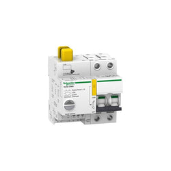
This Acti 9 Reflex iC60H is a low voltage integrated control circuit breaker. It combines integrated circuit breaker protection and load control for lighting control applications. It has 2P with 2 protected poles, rated current 10A and D tripping curve. Y1/Y2 inputs remote control voltage is 230VAC and 1A. They allow local and remote control of lighting. Y3 input remote control voltage is 24VDC and 5.5mA. Y3 allow easy connection to a Power Logic Controller or a Building Management System. Breaking capacity at 230VAC is 30kA according to IEC 60947-2 . Breaking capacity at 400VAC is 15kA according to IEC 60974-2. Electrical endurance goes up to 30000 cycles for AC-1 or AC-7a. Electrical endurance goes up to 6000 cycles for AC-5a or AC-5b and AC-7c. It is possible to associate a vigi block to have a differential protection.
Main
| Characteristic | Value(s) |
|---|---|
| Device application | Control Distribution |
| Range | Acti9 |
| product name | Reflex iC60 |
| Device short name | Reflex iC60H |
| Product or component type | Integrated control circuit breaker |
| Poles description | 2P |
| Number of protected poles | 2 |
| Network type | AC |
| Trip unit technology | Thermal-magnetic |
| Curve code | D |
Complementary
| Characteristic | Value(s) |
|---|---|
| [In] rated current | 10 A |
| Network frequency | 50/60 Hz |
| Breaking capacity code | H |
| Breaking capacity | 30 kA Icu at 220...240 V AC 50/60 Hz conforming to EN/IEC 60947-2 15 kA Icu at 380...415 V AC 50/60 Hz conforming to EN/IEC 60947-2 |
| [Ui] rated insulation voltage | 500 V AC |
| Contact position indicator | Yes |
| control type | Remote control by continuous command ON/OFF button Toggle Remote control by pulse |
| Control signal type | Impulse Maintained Maintained very low voltage |
| Local signalling | Red LED: fault Green LED: device ON Flashing LED: device overheat Flashing LED: device tripped Flashing LED: device ready |
| [Uc] control circuit voltage | 230 V AC 50/60 Hz 24 V AC 50/60 Hz 48 V AC 50/60 Hz 24 V DC 48 V DC |
| [Us] rated supply voltage | 230 V AC at 50/60 Hz |
| Mounting mode | Fixed |
| Mounting support | 35 mm symmetrical DIN rail |
| 9 mm pitches | 9 |
| Height | 84 mm |
| Width | 81 mm |
| Depth | 77 mm |
| Colour | White |
| Mechanical durability | 50000 cycles |
| Electrical durability | AC-1: 50000 cycles AC 50 Hz |
| Provision for padlocking | Padlockable |
| Locking options description | Padlock in OFF position |
| Earth-leakage protection | Separate block |
| Product compatibility | With PLC |

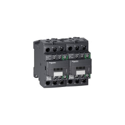
TeSys D reversing contactor - 3P - <= 440 V - 38 A AC-3 - 48...130 V AC/DC coil