
 1 year warranty

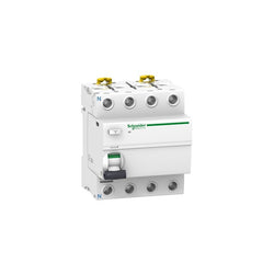
Acti 9 iID - RCCB - 4P - 40A - 500mA - type A

PLC Direct is not an authorized distributor. We offer a broad range of in-stock products with minimal lead time.
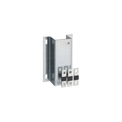
TeSys GV combination kit for circuit breaker and contactor association, for motor circuit breakers GV5, GV7. The kit comprises a depth adjustable metal bracket for mounting the breaker, links for the connection between circuit breaker and contactor, a cover on the links for protection against direct contact. For use with 3-pole contactors LC1D115, D150.
Main
| Characteristic | Value(s) |
|---|---|
| Range | TeSys |
| Product or Component Type | Kit for combination with connector |
| Device short name | GV7AC |
| Range compatibility | TeSys TeSys GV5 motor circuit breaker TeSys TeSys GV7 motor circuit breaker TeSys TeSys D contactor |
| Accessory / separate part category | Connection accessory |
| Product Compatibility | LC1D115 LC1D150 |
Complementary
| Characteristic | Value(s) |
|---|---|
| Kit composition | Adjustable mounting bracket(s) Terminal screw type connector Short terminal shield |
| Quantity per Set | Set of 1 |
| Product Weight | 1.21 lb(US) (0.55 kg) |

This Acti9 iPRD65r surge arrester protects 3P installations. It allows quick replacement of damaged cartridges. This Type 2 device is recommended for very high risk level and incoming panel board. It offers remote reporting of the "cartridge must be changed" message. It can be turned over to allow the phase/neutral/earth cables to enter through either the top or the bottom. The associated circuit breaker Isc breaking capacity can go up to 50kA. It is compatible with TT and TN-S earthing system. The Uc maximum continuous operating voltage in common mode (between phase and earth) is 460VAC. The Up Voltage protection level in common mode (between phase and earth) is 2.3kV. The Ue rated operational voltage is 230VAC or 400VAC +/- 10%. The product colour is white (RAL9003).The dimensions are (W) 54mm x (H) 85mm x (D) 69mm. The weight is 340g. The degree of protection is IP20 and IP40 in modular enclosure. The operating temperature is -25°C to 60°C. The storage temperature is -40°C to 85°C. This product is compliant with EN 61643-11 and IEC 61643-11 standards.
Main
| Characteristic | Value(s) |
|---|---|
| Range of product | IPRD |
| range of product | Acti9 |
| product name | Acti9 iPRD |
| Product or component type | Surge arrester with pluggable cartridge |
| Device short name | iPRD65r |
| Device application | Distribution |
| Standards | EN 61643-11:2012 IEC 61643-11:2011 |
| Product certifications | CE |
| Poles description | 3P |
| Remote signalling | With |
| Signal contacts composition | 1 SD (1 C/O) |
| Surge arrester type | Electrical distribution network |
| Earthing system | IT |
Complementary
| Characteristic | Value(s) |
|---|---|
| Surge arrester class type | Type 2 |
| Surge arrester technology | MOV |
| [Ue] rated operational voltage | 400 V AC (+/- 10 %) at 50/60 Hz |
| Nominal discharge current | Common mode: 20 kA (L/PE) |
| Maximum discharge current | Common mode: 65 kA L/PE |
| [Uc] maximum continuous operating voltage | Common mode: 460 V L/PE |
| Maximum [Up] voltage protection level | Common mode <2.3 kV type 2 L/PE |
| [Ut] temporary overvoltage | 337 V L/N 5 s withstand 1455 V L/PE 200 ms safe failure mode 1455 V N/PE 200 ms safe failure mode |
| Short-circuit withstand | 5 kA 415 V Ph/Ph |
| Disconnector device type | Associated circuit breaker iC60L 25 A curve C - Icu 25 kA Associated circuit breaker NG125H 50 A curve C - Icu 36 kA Associated circuit breaker NG125L 50 A curve C - Icu 50 kA Associated fuse gG 80 A - Icu 50 kA |
| Signalling circuit voltage | 0.25 A/250 V AC 50/60 Hz |
| Mounting mode | Clip-on (DIN rail) |
| 9 mm pitches | 6 |
| Height | 85 mm |
| Width | 54 mm |
| Depth | 69 mm |
| Product weight | 340 g |
| Colour | White (RAL 9003) |
| [Ipe] Ground residual current | 0.6 mA |
| Connections - terminals | Tunnel type terminal (top or bottom) 2.5â¦25 mm² rigid Tunnel type terminal (top or bottom) 4â¦16 mm² flexible Tunnel type terminal (top or bottom) 4â¦16 mm² flexible with ferrule |
| Wire stripping length | 14 mm |
| Tightening torque | 3.5 N.m |
| Targeted country | All |
| Compatibility code | IPRD65r |
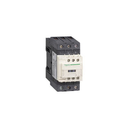
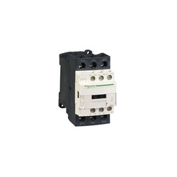
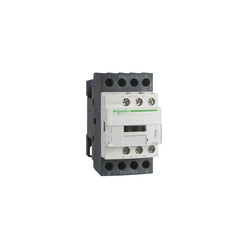
TeSys Deca contactor, 3 poles (3NO), for motor control applications up to 65A/690V AC-3 (30kW@400V). Rated 65A AC-3 30kW@400V, it includes a 48V DC coil and 1NO+1NC aux contacts. It provides a 48V DC coil with transient suppressor module, 1NO+1NC built-in auxiliary contacts (NC mirror certified), power connection by EverLink BTR screw connectors, control connection by screw clamp terminals. For operating rates until 3600 cycles/hour and environments until 60°C, it procures high reliability and durability. Compact (55mm width), DIN-rail mounting or screw fixing. Compact, DIN-rail mounting, it procures high reliability and durability. Multi standards certified (IEC, UL, CSA, CCC, EAC, Marine). Compact product, 55mm wide, for DIN-rail and panel mounting. Clear separation between power and control circuits, easy front access to coil and auxiliary contacts connections. Equipped with a 48V DC coil for easy integration to all control systems. Provides 2 built-in auxiliary contacts 1NO + 1NC, NC is a certified mirror contact suitable to be included in the control of safety systems. High electrical durability, guaranteed for 1.6 million cycles at 65A AC-3 440V, for demanding motor switching applications. Robust design with high making and breaking capacities up to 20 In. Power connections by EverLink BTR screw terminals providing constant tightening pressure.
Main
| Characteristic | Value(s) |
|---|---|
| Range | TeSys TeSys Deca |
| Range of Product | TeSys Deca |
| Product or Component Type | Contactor |
| Device short name | LC1D |
| Contactor application | Motor control Resistive load |
| Utilisation category | AC-4 AC-1 AC-3 |
| Poles description | 3P |
| [Ue] rated operational voltage | Power circuit <= 690 V AC 25...400 Hz Power circuit <= 300 V DC |
| [Ie] rated operational current | 80 A (at <140 °F (60 °C)) at <= 440 V AC AC-1 for power circuit 65 A (at <140 °F (60 °C)) at <= 440 V AC AC-3 for power circuit |
| [Uc] control circuit voltage | 48 V DC |
Complementary
| Characteristic | Value(s) |
|---|---|
| Motor power kW | 11 kW at 400 V AC 50/60 Hz (AC-4) 18.5 kW at 220...230 V AC 50/60 Hz (AC-3) 30 kW at 380...400 V AC 50/60 Hz (AC-3) 37 kW at 500 V AC 50/60 Hz (AC-3) 37 kW at 660...690 V AC 50/60 Hz (AC-3) |
| Maximum Horse Power Rating | 40 hp at 460/480 V AC 50/60 Hz for 3 phase motors 5 hp at 115 V AC 50/60 Hz for 1 phase motors 10 hp at 230/240 V AC 50/60 Hz for 1 phase motors 20 hp at 200/208 V AC 50/60 Hz for 3 phase motors 20 hp at 230/240 V AC 50/60 Hz for 3 phase motors 50 hp at 575/600 V AC 50/60 Hz for 3 phase motors |
| Compatibility code | LC1D |
| Pole contact composition | 3 NO |
| Protective cover | With |
| [Ith] conventional free air thermal current | 10 A (at 140 °F (60 °C)) for signalling circuit 80 A (at 140 °F (60 °C)) for power circuit |
| Irms rated making capacity | 140 A AC for signalling circuit conforming to IEC 60947-5-1 250 A DC for signalling circuit conforming to IEC 60947-5-1 1000 A at 440 V for power circuit conforming to IEC 60947 |
| Rated breaking capacity | 1000 A at 440 V for power circuit conforming to IEC 60947 |
| [Icw] rated short-time withstand current | 640 A 104 °F (40 °C) - 10 s for power circuit 900 A 104 °F (40 °C) - 1 s for power circuit 110 A 104 °F (40 °C) - 10 min for power circuit 260 A 104 °F (40 °C) - 1 min for power circuit 100 A - 1 s for signalling circuit 120 A - 500 ms for signalling circuit 140 A - 100 ms for signalling circuit |
| Associated fuse rating | 10 A gG for signalling circuit conforming to IEC 60947-5-1 125 A gG at <= 690 V coordination type 1 for power circuit 125 A gG at <= 690 V coordination type 2 for power circuit |
| Average impedance | 1.5 mOhm - Ith 80 A 50 Hz for power circuit |
| Power dissipation per pole | 9.6 W AC-1 6.3 W AC-3 |
| [Ui] rated insulation voltage | Power circuit 600 V CSA Power circuit 600 V UL Signalling circuit 690 V IEC 60947-1 Signalling circuit 600 V CSA Signalling circuit 600 V UL Power circuit 690 V IEC 60947-4-1 |
| Overvoltage category | III |
| pollution degree | 3 |
| [Uimp] rated impulse withstand voltage | 6 kV IEC 60947 |
| Safety reliability level | B10d = 1369863 cycles contactor with nominal load EN/ISO 13849-1 B10d = 20000000 cycles contactor with mechanical load EN/ISO 13849-1 |
| Mechanical durability | 10 Mcycles |
| Electrical durability | 0.5 Mcycles 80 A AC-1 <= 440 V 1.45 Mcycles 65 A AC-3 <= 440 V |
| Control circuit type | DC standard |
| Coil technology | Built-in bidirectional peak limiting diode suppressor |
| Control circuit voltage limits | 0.1...0.3 Uc (-40â¦158 °F (-40â¦70 °C)):drop-out DC 0.75...1.25 Uc (-40â¦140 °F (-40â¦60 °C)):operational DC 1...1.25 Uc (140â¦158 °F (60â¦70 °C)):operational DC |
| Inrush power in W | 19 W 68 °F (20 °C)) |
| Hold-in power consumption in W | 7.4 W 68 °F (20 °C) |
| Operating time | 50 ±15 % ms closing 16...24 ms opening |
| Time constant | 34 ms |
| Maximum operating rate | 3600 cyc/h at 60 °C |
| Connections - terminals | Control circuit: screw clamp terminals 2 0.002â¦0.004 in² (1â¦2.5 mm²) - cable stiffness: flexible with cable end Control circuit: screw clamp terminals 1 0.002â¦0.006 in² (1â¦4 mm²) - cable stiffness: flexible without cable end Control circuit: screw clamp terminals 2 0.002â¦0.006 in² (1â¦4 mm²) - cable stiffness: flexible without cable end Control circuit: screw clamp terminals 1 0.002â¦0.006 in² (1â¦4 mm²) - cable stiffness: flexible with cable end Control circuit: screw clamp terminals 1 0.002â¦0.006 in² (1â¦4 mm²) - cable stiffness: solid without cable end Control circuit: screw clamp terminals 2 0.002â¦0.006 in² (1â¦4 mm²) - cable stiffness: solid without cable end Power circuit: screw connection 1 0.002â¦0.05 in² (1â¦35 mm²) - cable stiffness: flexible without cable end Power circuit: screw connection 2 0.002â¦0.04 in² (1â¦25 mm²) - cable stiffness: flexible without cable end Power circuit: screw connection 1 0.002â¦0.05 in² (1â¦35 mm²) - cable stiffness: flexible with cable end Power circuit: screw connection 2 0.002â¦0.04 in² (1â¦25 mm²) - cable stiffness: flexible with cable end Power circuit: screw connection 1 0.002â¦0.05 in² (1â¦35 mm²) - cable stiffness: solid without cable end Power circuit: screw connection 2 0.002â¦0.04 in² (1â¦25 mm²) - cable stiffness: solid without cable end |
| Tightening torque | Control circuit 15.05 lbf.in (1.7 N.m) EverLink BTR screw connectors flat à 6 mm Control circuit 15.05 lbf.in (1.7 N.m) EverLink BTR screw connectors Philips No 2 Power circuit 70.8 lbf.in (8 N.m) EverLink BTR screw connectors 0.04â¦0.05 in² (25â¦35 mm²) hexagonal 0.2 in (4 mm) Power circuit 44.3 lbf.in (5 N.m) EverLink BTR screw connectors 0.002â¦0.04 in² (1â¦25 mm²) hexagonal 0.2 in (4 mm) Control circuit 15.05 lbf.in (1.7 N.m) EverLink BTR screw connectors pozidriv No 2 Power circuit 22.1 lbf.in (2.5 N.m) EverLink BTR screw connectors pozidriv No 2 |
| Auxiliary contact composition | 1 NO + 1 NC |
| Auxiliary contacts type | Mechanically linked 1 NO + 1 NC IEC 60947-5-1 Mirror contact 1 NC IEC 60947-4-1 |
| Signalling circuit frequency | 25...400 Hz |
| Minimum switching voltage | 17 V for signalling circuit |
| Minimum switching current | 5 mA for signalling circuit |
| Insulation resistance | > 10 MOhm for signalling circuit |
| Non-overlap time | 1.5 ms on de-energisation between NC and NO contact 1.5 ms on energisation between NC and NO contact |
| Mounting Support | Rail Plate |
"TeSys K contactor, 3 poles (3NO), for motor control applications up to 16A/690V AC-3 (4kW@440V)," "and for non-inductive load control applications up to 20A/690V AC-1." "It provides a 24V 50/60Hz AC coil,1NO built-in auxiliary contact, connection by screw clamp terminals." "For operating rates until 600 cycles/hour and environments until 50°C, it procures reliability and durability to standard applications." "With feature (90mm width), DIN-rail mounting or screw fixing." "Multi standards certified (IEC, UL, CSA, CCC, EAC)
Main
| Characteristic | Value(s) |
|---|---|
| Range | TeSys |
| product name | TeSys K |
| Product or component type | Reversing contactor |
| Device short name | LC2K |
| Device application | Control |
| Contactor application | Motor control |
| Utilisation category | AC-3 AC-3e AC-4 |
| Device presentation | Preassembled with reversing power busbar |
| Poles description | 3P |
| power pole contact composition | 3 NO |
| [Ue] rated operational voltage | Power circuit: 690 V AC 50/60 Hz Signalling circuit: <= 690 V AC 50/60 Hz |
| [Ie] rated operational current | 16 A (at <60 °C) at <= 440 V AC AC-3 for power circuit 16 A (at <60 °C) at <= 440 V AC AC-3e for power circuit |
| Motor power kW | 4 kW at 220...230 V AC 50/60 Hz 7.5 kW at 380...415 V AC 50/60 Hz 5.5 kW at 440 V AC 50/60 Hz 4 kW at 690 V AC 50/60 Hz |
| Control circuit type | AC at 50/60 Hz |
| [Uc] control circuit voltage | 24 V AC 50/60 Hz |
| Auxiliary contact composition | 1 NO |
| [Uimp] rated impulse withstand voltage | 8 kV |
| Overvoltage category | III |
| [Ith] conventional free air thermal current | 20 A (at 60 °C) for power circuit 10 A (at 50 °C) for signalling circuit |
| Irms rated making capacity | 160 A AC for power circuit conforming to IEC 60947 110 A AC for signalling circuit conforming to IEC 60947 |
| Rated breaking capacity | 110 A at 440 V conforming to IEC 60947 80 A at 500 V conforming to IEC 60947 70 A at 660...690 V conforming to IEC 60947 |
| [Icw] rated short-time withstand current | 115 A 50 °C - 1 s for power circuit 105 A 50 °C - 5 s for power circuit 100 A 50 °C - 10 s for power circuit 75 A 50 °C - 30 s for power circuit 55 A 50 °C - 1 min for power circuit 50 A 50 °C - 3 min for power circuit 25 A 50 °C - >= 15 min for power circuit 80 A - 1 s for signalling circuit 90 A - 500 ms for signalling circuit 110 A - 100 ms for signalling circuit |
| Associated fuse rating | 25 A gG at <= 440 V for power circuit 25 A aM for power circuit 10 A gG for signalling circuit conforming to IEC 60947 10 A gG for signalling circuit conforming to VDE 0660 |
| Average impedance | 3 mOhm - Ith 20 A 50 Hz for power circuit |
| [Ui] rated insulation voltage | Power circuit: 600 V conforming to UL 508 Power circuit: 690 V conforming to IEC 60947-4-1 Signalling circuit: 690 V conforming to IEC 60947-4-1 Signalling circuit: 690 V conforming to IEC 60947-5-1 Signalling circuit: 600 V conforming to UL 508 Power circuit: 600 V conforming to CSA C22.2 No 14 Signalling circuit: 600 V conforming to CSA C22.2 No 14 |
| Electrical durability | 1.3 Mcycles 16 A AC-3 at Ue <= 440 V 1.3 Mcycles 16 A AC-3e at Ue <= 440 V |
| Interlocking type | Mechanical |
| Mounting support | Rail Plate |
| Standards | EN/IEC 60947-4-1 GB/T 14048.4 UL 60947-4-1 CSA C22.2 No 60947-4-1 JIS C8201-4-1 |
| Product certifications | CB Scheme CCC UL CSA EAC CE UKCA |
| Connections - terminals | Screw clamp terminals 1 cable(s) 1.5â¦4 mm²solid Screw clamp terminals 1 cable(s) 0.75â¦4 mm²flexible without cable end Screw clamp terminals 1 cable(s) 0.34â¦2.5 mm²flexible with cable end Screw clamp terminals 2 cable(s) 1.5â¦4 mm²solid Screw clamp terminals 2 cable(s) 0.75â¦4 mm²flexible without cable end Screw clamp terminals 2 cable(s) 0.34â¦1.5 mm²flexible with cable end |
| Tightening torque | 0.8â¦1.3 N.m - on screw clamp terminals Philips No 2 0.8â¦1.3 N.m - on screw clamp terminals flat à 6 mm 0.8â¦1.3 N.m - on screw clamp terminals pozidriv No 2 |
| Operating time | 10...20 ms coil energisation and NO closing 10...20 ms coil de-energisation and NO opening |
| Safety reliability level | B10d = 1369863 cycles contactor with nominal load conforming to EN/ISO 13849-1 B10d = 20000000 cycles contactor with mechanical load conforming to EN/ISO 13849-1 |
| Mechanical durability | 5 Mcycles |
| Maximum operating rate | 3600 cyc/h |
Complementary
| Characteristic | Value(s) |
|---|---|
| Control circuit voltage limits | Operational: 0.8...1.15 Uc (at <50 °C) Drop-out: 0.2...0.75 Uc (at <50 °C) |
| Inrush power in VA | 30 VA (at 20 °C) |
| Hold-in power consumption in VA | 4.5 VA (at 20 °C) |
| Heat dissipation | 1.3 W |
| Auxiliary contacts type | type instantaneous 1 NO |
| Signalling circuit frequency | <= 400 Hz |
| Minimum switching current | 5 mA for signalling circuit |
| Minimum switching voltage | 17 V for signalling circuit |
| Non overlap distance | 0.5 mm |
| Insulation resistance | > 10 MOhm for signalling circuit |
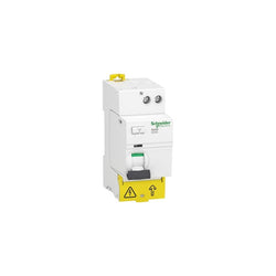
residual current circuit breaker (RCCB), Acti9 iID40, 1P+N, 40 A, 30 mA, A type

TeSys K contactor - 4P (4 NO) - AC-1 <= 440 V 20 A - 24 V DC coil

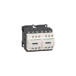
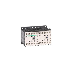
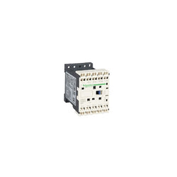
TeSys Deca reversing contactor, 3 poles (3NO), for motor control applications up to 18A/690V AC-3 (7.5kW@400V). Rated 18A AC-3 7.5kW@400V, it includes a 110V 50/60Hz AC coil, 2NO+2NC aux contacts, a mechanical interlock. It provides 110V 50/60Hz AC coils, 2NO+2NC built-in auxiliary contacts (NC mirror certified), connection by screw clamp terminals. For operating rates until 3600 cycles/hour and environments until 60°C, it procures high reliability and durability. Compact (90mm width), DIN-rail mounting or screw fixing. With pre-wired reversing power connections, mechanical interlock (without electrical interlocking). Multi standards certified (IEC, UL, CSA, CCC, EAC, Marine). Assembled with mechanical interlock and pre-wired reversing circuit. Clear separation between power and control circuits, easy front access to coil and auxiliary contacts connections. Equipped with a 110V AC coil that can be supplied at 50Hz or 60Hz. Provides 4 built-in auxiliary contacts 2NO + 2NC, NC contacts are mirror certified suitable to be included in the control of safety systems. High electrical durability, guaranteed for 2 million cycles at 18A AC-3 440V, for demanding motor switching applications. Robust design with high making and breaking capacities up to 20 In. Connection by screw clamp terminals.
Main
| Characteristic | Value(s) |
|---|---|
| Range | TeSys TeSys Deca |
| product name | TeSys D TeSys Deca |
| Product or Component Type | Reversing contactor |
| Device short name | LC2D |
| Contactor application | Resistive load Motor control |
| Utilisation category | AC-1 AC-3 AC-3e |
| Device presentation | Preassembled with reversing power busbar |
| Poles description | 3P |
| power pole contact composition | 3 NO |
| [Ue] rated operational voltage | Power circuit <= 690 V AC 25...400 Hz Power circuit <= 300 V DC |
| [Ie] rated operational current | 18 A (at <140 °F (60 °C)) at <= 440 V AC AC-3 for power circuit 32 A (at <140 °F (60 °C)) at <= 440 V AC AC-1 for power circuit 18 A (at <140 °F (60 °C)) at <= 440 V AC AC-3e for power circuit |
| Motor power kW | 4 kW at 220...230 V AC 50-60 Hz 7.5 kW at 380...400 V AC 50-60 Hz 9 kW at 415 V AC 50-60 Hz 9 kW at 440 V AC 50-60 Hz 10 kW at 500 V AC 50-60 Hz 10 kW at 660...690 V AC 50-60 Hz |
| motor power HP (UL / CSA) | 1 hp at 115 V AC 60 Hz for 1 phase motors 3 hp at 230/240 V AC 60 Hz for 1 phase motors 5 hp at 200/208 V AC 60 Hz for 3 phase motors 5 hp at 230/240 V AC 60 Hz for 3 phase motors 10 hp at 460/480 V AC 60 Hz for 3 phase motors 15 hp at 575/600 V AC 60 Hz for 3 phase motors |
| Control circuit type | AC 50/60 Hz |
| [Uc] control circuit voltage | 110 V AC 50/60 Hz |
| Auxiliary contact composition | 1 NO + 1 NC |
| [Uimp] rated impulse withstand voltage | 6 kV IEC 60947 |
| Overvoltage category | III |
| [Ith] conventional free air thermal current | 10 A (at 140 °F (60 °C)) for signalling circuit 32 A (at 140 °F (60 °C)) for power circuit |
| Irms rated making capacity | 140 A AC for signalling circuit conforming to IEC 60947-5-1 250 A DC for signalling circuit conforming to IEC 60947-5-1 300 A at 440 V for power circuit conforming to IEC 60947 |
| Rated breaking capacity | 300 A at 440 V for power circuit conforming to IEC 60947 |
| [Icw] rated short-time withstand current | 40 A 104 °F (40 °C) - 10 min for power circuit 84 A 104 °F (40 °C) - 1 min for power circuit 145 A 104 °F (40 °C) - 10 s for power circuit 240 A 104 °F (40 °C) - 1 s for power circuit 100 A - 1 s for signalling circuit 120 A - 500 ms for signalling circuit 140 A - 100 ms for signalling circuit |
| Associated fuse rating | 10 A gG for signalling circuit conforming to IEC 60947-5-1 50 A gG at <= 690 V coordination type 1 for power circuit 35 A gG at <= 690 V coordination type 2 for power circuit |
| Average impedance | 2.5 mOhm - Ith 32 A 50 Hz for power circuit |
| [Ui] rated insulation voltage | Power circuit 690 V IEC 60947-4-1 Power circuit 600 V CSA Power circuit 600 V UL Signalling circuit 690 V IEC 60947-1 Signalling circuit 600 V CSA Signalling circuit 600 V UL |
| Electrical durability | 1.65 Mcycles 18 A AC-3 <= 440 V 1 Mcycles 32 A AC-1 <= 440 V 1.65 Mcycles 18 A AC-3e <= 440 V |
| Power dissipation per pole | 0.8 W AC-3 2.5 W AC-1 0.8 W AC-3e |
| Front cover | With |
| Interlocking type | Mechanical |
| Mounting Support | Plate Rail |
| Standards | CSA C22.2 No 14 EN 60947-4-1 EN 60947-5-1 IEC 60947-4-1 IEC 60947-5-1 UL 508 IEC 60335-1 |
| Product Certifications | DNV CSA CCC UL GL LROS (Lloyds register of shipping) BV RINA GOST UKCA |
| Connections - terminals | Control circuit screw clamp terminals 1 0.002â¦0.006 in² (1â¦4 mm²)flexible without cable end Control circuit screw clamp terminals 2 0.002â¦0.006 in² (1â¦4 mm²)flexible without cable end Control circuit screw clamp terminals 1 0.002â¦0.006 in² (1â¦4 mm²)flexible with cable end Control circuit screw clamp terminals 2 0.002â¦0.004 in² (1â¦2.5 mm²)flexible with cable end Control circuit screw clamp terminals 1 0.002â¦0.006 in² (1â¦4 mm²)solid Control circuit screw clamp terminals 2 0.002â¦0.006 in² (1â¦4 mm²)solid Power circuit screw clamp terminals 1 0.002â¦0.009 in² (1.5â¦6 mm²)flexible without cable end Power circuit screw clamp terminals 2 0.002â¦0.009 in² (1.5â¦6 mm²)flexible without cable end Power circuit screw clamp terminals 1 0.002â¦0.009 in² (1â¦6 mm²)flexible with cable end Power circuit screw clamp terminals 2 0.002â¦0.006 in² (1â¦4 mm²)flexible with cable end Power circuit screw clamp terminals 1 0.002â¦0.009 in² (1.5â¦6 mm²)solid Power circuit screw clamp terminals 2 0.002â¦0.009 in² (1.5â¦6 mm²)solid |
| Tightening torque | Power circuit 15.05 lbf.in (1.7 N.m) screw clamp terminals flat à 6 mm Power circuit 15.05 lbf.in (1.7 N.m) screw clamp terminals Philips No 2 Control circuit 15.05 lbf.in (1.7 N.m) screw clamp terminals flat à 6 mm Control circuit 15.05 lbf.in (1.7 N.m) screw clamp terminals Philips No 2 Control circuit 15.05 lbf.in (1.7 N.m) screw clamp terminals pozidriv No 2 Power circuit 22.1 lbf.in (2.5 N.m) screw clamp terminals pozidriv No 2 |
| Operating time | 12...22 ms closing 4...19 ms opening |
| Safety reliability level | B10d = 1369863 cycles contactor with nominal load EN/ISO 13849-1 B10d = 20000000 cycles contactor with mechanical load EN/ISO 13849-1 |
| Mechanical durability | 15 Mcycles |
| Maximum operating rate | 3600 cyc/h 140 °F (60 °C) |
Complementary
| Characteristic | Value(s) |
|---|---|
| Coil technology | Without built-in suppressor module |
| Control circuit voltage limits | 0.3...0.6 Uc (-40â¦158 °F (-40â¦70 °C)):drop-out AC 50/60 Hz 0.8...1.1 Uc (-40â¦140 °F (-40â¦60 °C)):operational AC 50 Hz 0.85...1.1 Uc (-40â¦140 °F (-40â¦60 °C)):operational AC 60 Hz 1...1.1 Uc (140â¦158 °F (60â¦70 °C)):operational AC 50/60 Hz |
| Inrush power in VA | 70 VA 60 Hz cos phi 0.75 (at 68 °F (20 °C)) 70 VA 50 Hz cos phi 0.75 (at 68 °F (20 °C)) |
| Hold-in power consumption in VA | 7.5 VA 60 Hz cos phi 0.3 (at 68 °F (20 °C)) 7 VA 50 Hz cos phi 0.3 (at 68 °F (20 °C)) |
| Heat dissipation | 2â¦3 W 50/60 Hz |
| Auxiliary contacts type | Mechanically linked 1 NO + 1 NC IEC 60947-5-1 Mirror contact 1 NC IEC 60947-4-1 |
| Signalling circuit frequency | 25...400 Hz |
| Minimum switching current | 5 mA for signalling circuit |
| Minimum switching voltage | 17 V for signalling circuit |
| Non-overlap time | 1.5 ms on de-energisation between NC and NO contact 1.5 ms on energisation between NC and NO contact |
| Insulation resistance | > 10 MOhm for signalling circuit |

TeSys Deca contactor, 3 poles (3NO), for motor control applications up to 25A/690V AC-3/3e (11kW@400V). They can be used to create motor starters for almost any type of application. It provides a 24V DC coil with transient suppressor module, 1NO+1NC built-in auxiliary contacts (NC mirror certified), connection by ring-lugs screw terminals. For operating rates until 3600 cycles/hour and environments until 60°C, it procures high reliability and durability. Compact (45mm width), DIN-rail mounting or screw fixing. Contactor is rated for 7.5HP at 200 to 208VAC, 7.5HP at 240VAC, 15HP at 480VAC and 20HP at 600VAC three phase. Multi standards certified (IEC, UL, CSA, CCC, EAC, Marine). Contactor is supplied with a 24 VDC coil with transient suppressor module. Contactor has one normally open and one normally closed auxiliary contact built-in as standard. The NC contact is mirror certified. Ring-lug screw terminals are used for load and auxiliary connections. An extensive line of accessories makes it easy to meet the requirements of most applications. The contactor is 3.35 inches tall, 1.77 inches wide and 3.98 inches deep. It weighs 1.17 lbs. Contactor is certified to UL, CSA, IEC, CCC, EAC and Marine standards.
Main
| Characteristic | Value(s) |
|---|---|
| Range of Product | TeSys Deca |
| Product or Component Type | Contactor |
| Device short name | LC1D |
| Contactor application | Motor control Resistive load |
| Utilisation category | AC-3 AC-1 AC-4 AC-3e |
| Poles description | 3P |
| [Ue] rated operational voltage | Power circuit <= 690 V AC 25...400 Hz Power circuit <= 300 V DC |
| [Ie] rated operational current | 25 A (at <140 °F (60 °C)) at <= 440 V AC AC-3 for power circuit 40 A (at <140 °F (60 °C)) at <= 440 V AC AC-1 for power circuit 25 A (at <140 °F (60 °C)) at <= 440 V AC AC-3e for power circuit |
| [Uc] control circuit voltage | 24 V DC |
Complementary
| Characteristic | Value(s) |
|---|---|
| Motor power kW | 5.5 kW at 220...230 V AC 50/60 Hz (AC-3) 11 kW at 380...400 V AC 50/60 Hz (AC-3) 11 kW at 415...440 V AC 50/60 Hz (AC-3) 15 kW at 500 V AC 50/60 Hz (AC-3) 15 kW at 660...690 V AC 50/60 Hz (AC-3) 5.5 kW at 400 V AC 50/60 Hz (AC-4) 5.5 kW at 220...230 V AC 50/60 Hz (AC-3e) 11 kW at 380...400 V AC 50/60 Hz (AC-3e) 11 kW at 415...440 V AC 50/60 Hz (AC-3e) 15 kW at 500 V AC 50/60 Hz (AC-3e) 15 kW at 660...690 V AC 50/60 Hz (AC-3e) |
| Maximum Horse Power Rating | 3 hp at 230/240 V AC 50/60 Hz for 1 phase motors 2 hp at 115 V AC 50/60 Hz for 1 phase motors 7.5 hp at 230/240 V AC 50/60 Hz for 3 phase motors 15 hp at 460/480 V AC 50/60 Hz for 3 phase motors 20 hp at 575/600 V AC 50/60 Hz for 3 phase motors 7.5 hp at 200/208 V AC 50/60 Hz for 3 phase motors |
| Compatibility code | LC1D |
| Pole contact composition | 3 NO |
| Protective cover | With |
| [Ith] conventional free air thermal current | 10 A (at 140 °F (60 °C)) for signalling circuit 40 A (at 140 °F (60 °C)) for power circuit |
| Irms rated making capacity | 140 A AC for signalling circuit conforming to IEC 60947-5-1 250 A DC for signalling circuit conforming to IEC 60947-5-1 450 A at 440 V for power circuit conforming to IEC 60947 |
| Rated breaking capacity | 450 A at 440 V for power circuit conforming to IEC 60947 |
| [Icw] rated short-time withstand current | 240 A 104 °F (40 °C) - 10 s for power circuit 380 A 104 °F (40 °C) - 1 s for power circuit 50 A 104 °F (40 °C) - 10 min for power circuit 120 A 104 °F (40 °C) - 1 min for power circuit 100 A - 1 s for signalling circuit 120 A - 500 ms for signalling circuit 140 A - 100 ms for signalling circuit |
| Associated fuse rating | 10 A gG for signalling circuit conforming to IEC 60947-5-1 63 A gG at <= 690 V coordination type 1 for power circuit 40 A gG at <= 690 V coordination type 2 for power circuit |
| Average impedance | 2 mOhm - Ith 40 A 50 Hz for power circuit |
| Power dissipation per pole | 3.2 W AC-1 1.25 W AC-3 1.25 W AC-3e |
| [Ui] rated insulation voltage | Power circuit 690 V IEC 60947-4-1 Power circuit 600 V CSA Power circuit 600 V UL Signalling circuit 690 V IEC 60947-1 Signalling circuit 600 V CSA Signalling circuit 600 V UL |
| Overvoltage category | III |
| pollution degree | 3 |
| [Uimp] rated impulse withstand voltage | 6 kV IEC 60947 |
| Safety reliability level | B10d = 1369863 cycles contactor with nominal load EN/ISO 13849-1 B10d = 20000000 cycles contactor with mechanical load EN/ISO 13849-1 |
| Mechanical durability | 30 Mcycles |
| Electrical durability | 1.65 Mcycles 25 A AC-3 <= 440 V 1.4 Mcycles 40 A AC-1 <= 440 V 1.65 Mcycles 25 A AC-3e <= 440 V |
| Control circuit type | DC standard |
| Coil technology | Built-in bidirectional peak limiting diode suppressor |
| Control circuit voltage limits | 0.1...0.25 Uc (-40â¦158 °F (-40â¦70 °C)):drop-out DC 0.7...1.25 Uc (-40â¦140 °F (-40â¦60 °C)):operational DC 1...1.25 Uc (140â¦158 °F (60â¦70 °C)):operational DC |
| Inrush power in W | 5.4 W 68 °F (20 °C)) |
| Hold-in power consumption in W | 5.4 W 68 °F (20 °C) |
| Operating time | 63 ±15 % ms closing 20 ±20 % ms opening |
| Time constant | 28 ms |
| Maximum operating rate | 3600 cyc/h at 60 °C |
| Connections - terminals | Control circuit: lugs-ring terminals - external diameter: 0.3 in (8 mm) Power circuit: lugs-ring terminals - external diameter: 0.4 in (10 mm) |
| Tightening torque | Control circuit 15.05 lbf.in (1.7 N.m) lugs-ring terminals flat à 6 mm M3.5 Control circuit 15.05 lbf.in (1.7 N.m) lugs-ring terminals Philips No 2 M3.5 Power circuit 22.1 lbf.in (2.5 N.m) lugs-ring terminals flat à 8 mm M4 Power circuit 22.1 lbf.in (2.5 N.m) lugs-ring terminals Philips No 2 M4 Control circuit 15.05 lbf.in (1.7 N.m) screw clamp terminals pozidriv No 2 Power circuit 22.1 lbf.in (2.5 N.m) screw clamp terminals pozidriv No 2 |
| Auxiliary contact composition | 1 NO + 1 NC |
| Auxiliary contacts type | Mechanically linked 1 NO + 1 NC IEC 60947-5-1 Mirror contact 1 NC IEC 60947-4-1 |
| Signalling circuit frequency | 25...400 Hz |
| Minimum switching voltage | 17 V for signalling circuit |
| Minimum switching current | 5 mA for signalling circuit |
| Insulation resistance | > 10 MOhm for signalling circuit |
| Non-overlap time | 1.5 ms on de-energisation between NC and NO contact 1.5 ms on energisation between NC and NO contact |
| Mounting Support | Rail Plate |
TeSys Deca contactor, 4 poles (2NO+2NC), for non-inductive load applications up to 32A/690V AC-1. They can be used to create motor starters for almost any type of application. It provides a 42V 50/60Hz AC coil, 1NO+1NC built-in auxiliary contacts (NC mirror certified), connection by screw clamp terminals. For operating rates until 3600 cycles/hour and environments until 60°C, it procures high reliability and durability. Compact (45mm width), DIN-rail mounting or screw fixing. Power contacts have a 32A resistive load rating. Multi standards certified (IEC, UL, CSA, CCC, EAC, Marine). Contactor has one normally open and one normally closed auxiliary contact built-in as standard. The NC contact is mirror certified. Screw clamp terminals are used for load and auxiliary connections. An extensive line of accessories makes it easy to meet the requirements of most applications. The contactor is 4.13 inches tall, 1.77 inches wide and 3.90 inches deep. It weighs 0.94 lbs. Contactor is certified to UL, CSA, IEC, CCC, EAC and Marine standards.
Main
| Characteristic | Value(s) |
|---|---|
| Range of Product | TeSys Deca |
| Product or Component Type | Contactor |
| Device short name | LC1D |
| Contactor application | Resistive load |
| Utilisation category | AC-1 |
| Poles description | 4P |
| [Ue] rated operational voltage | Power circuit <= 690 V AC 25...400 Hz |
| [Ie] rated operational current | 32 A (at <140 °F (60 °C)) at <= 440 V AC AC-1 for power circuit |
| [Uc] control circuit voltage | 42 V AC 50/60 Hz |
Complementary
| Characteristic | Value(s) |
|---|---|
| Compatibility code | LC1D |
| Pole contact composition | 2 NO + 2 NC |
| Protective cover | With |
| [Ith] conventional free air thermal current | 10 A (at 140 °F (60 °C)) for signalling circuit 32 A (at 140 °F (60 °C)) for power circuit |
| Irms rated making capacity | 140 A AC for signalling circuit conforming to IEC 60947-5-1 250 A DC for signalling circuit conforming to IEC 60947-5-1 300 A at 440 V for power circuit conforming to IEC 60947 |
| Rated breaking capacity | 300 A at 440 V for power circuit conforming to IEC 60947 |
| [Icw] rated short-time withstand current | 145 A 104 °F (40 °C) - 10 s for power circuit 240 A 104 °F (40 °C) - 1 s for power circuit 40 A 104 °F (40 °C) - 10 min for power circuit 84 A 104 °F (40 °C) - 1 min for power circuit 100 A - 1 s for signalling circuit 120 A - 500 ms for signalling circuit 140 A - 100 ms for signalling circuit |
| Associated fuse rating | 10 A gG for signalling circuit conforming to IEC 60947-5-1 50 A gG at <= 690 V coordination type 1 for power circuit 35 A gG at <= 690 V coordination type 2 for power circuit |
| Average impedance | 2.5 mOhm - Ith 32 A 50 Hz for power circuit |
| Power dissipation per pole | 2.5 W AC-1 |
| [Ui] rated insulation voltage | Power circuit 690 V IEC 60947-4-1 Power circuit 600 V CSA Power circuit 600 V UL Signalling circuit 690 V IEC 60947-1 Signalling circuit 600 V CSA Signalling circuit 600 V UL |
| Overvoltage category | III |
| pollution degree | 3 |
| [Uimp] rated impulse withstand voltage | 6 kV IEC 60947 |
| Safety reliability level | B10d = 1369863 cycles contactor with nominal load EN/ISO 13849-1 B10d = 20000000 cycles contactor with mechanical load EN/ISO 13849-1 |
| Mechanical durability | 15 Mcycles |
| Electrical durability | 1 Mcycles 32 A AC-1 <= 440 V |
| Control circuit type | AC 50/60 Hz |
| Coil technology | Without built-in suppressor module |
| Control circuit voltage limits | 0.3...0.6 Uc (-40â¦140 °F (-40â¦60 °C)):drop-out AC 50/60 Hz 0.8...1.1 Uc (-40â¦140 °F (-40â¦60 °C)):operational AC 50 Hz 0.85...1.1 Uc (-40â¦140 °F (-40â¦60 °C)):operational AC 60 Hz |
| Inrush power in VA | 70 VA 60 Hz cos phi 0.75 (at 68 °F (20 °C)) 70 VA 50 Hz cos phi 0.75 (at 68 °F (20 °C)) |
| Hold-in power consumption in VA | 7.5 VA 60 Hz cos phi 0.3 (at 68 °F (20 °C)) 7 VA 50 Hz cos phi 0.3 (at 68 °F (20 °C)) |
| Heat dissipation | 2â¦3 W at 50/60 Hz |
| Operating time | 12...22 ms closing 4...19 ms opening |
| Maximum operating rate | 3600 cyc/h at 60 °C |
| Connections - terminals | Control circuit: screw clamp terminals 1 0.002â¦0.006 in² (1â¦4 mm²) - cable stiffness: flexible without cable end Control circuit: screw clamp terminals 2 0.002â¦0.006 in² (1â¦4 mm²) - cable stiffness: flexible without cable end Control circuit: screw clamp terminals 1 0.002â¦0.006 in² (1â¦4 mm²) - cable stiffness: flexible with cable end Control circuit: screw clamp terminals 2 0.002â¦0.004 in² (1â¦2.5 mm²) - cable stiffness: flexible with cable end Control circuit: screw clamp terminals 1 0.002â¦0.006 in² (1â¦4 mm²) - cable stiffness: solid without cable end Control circuit: screw clamp terminals 2 0.002â¦0.006 in² (1â¦4 mm²) - cable stiffness: solid without cable end Power circuit: screw clamp terminals 1 0.004â¦0.02 in² (2.5â¦10 mm²) - cable stiffness: flexible without cable end Power circuit: screw clamp terminals 2 0.004â¦0.02 in² (2.5â¦10 mm²) - cable stiffness: flexible without cable end Power circuit: screw clamp terminals 1 0.004â¦0.02 in² (2.5â¦10 mm²) - cable stiffness: flexible with cable end Power circuit: screw clamp terminals 2 0.004â¦0.02 in² (2.5â¦10 mm²) - cable stiffness: flexible with cable end Power circuit: screw clamp terminals 1 0.004â¦0.02 in² (2.5â¦16 mm²) - cable stiffness: solid without cable end Power circuit: screw clamp terminals 2 0.004â¦0.02 in² (2.5â¦16 mm²) - cable stiffness: solid without cable end |
| Tightening torque | Control circuit 15.05 lbf.in (1.7 N.m) screw clamp terminals flat à 6 mm Control circuit 15.05 lbf.in (1.7 N.m) screw clamp terminals Philips No 2 Control circuit 15.05 lbf.in (1.7 N.m) screw clamp terminals pozidriv No 2 Power circuit 15.9 lbf.in (1.8 N.m) screw clamps terminals flat à 6 mm Power circuit 15.9 lbf.in (1.8 N.m) screw clamps terminals Philips No 2 Power circuit 15.9 lbf.in (1.8 N.m) screw clamp terminals pozidriv No 2 |
| Auxiliary contact composition | 1 NO + 1 NC |
| Auxiliary contacts type | Mechanically linked 1 NO + 1 NC IEC 60947-5-1 Mirror contact 1 NC IEC 60947-4-1 |
| Signalling circuit frequency | 25...400 Hz |
| Minimum switching voltage | 17 V for signalling circuit |
| Minimum switching current | 5 mA for signalling circuit |
| Insulation resistance | > 10 MOhm for signalling circuit |
| Non-overlap time | 1.5 ms on de-energisation between NC and NO contact 1.5 ms on energisation between NC and NO contact |
| Mounting Support | Plate Rail |

EasyPact TVS contactor 3P(3 NO) - AC-3 - = 440 V 32A - 110 V AC coil

TeSys D contactor - 4P(4 NO) - AC-1 - <= 440 V 40 A - 400 V AC 50/60 Hz coil

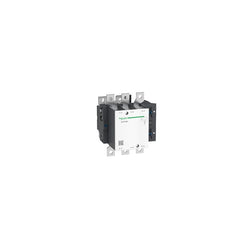
TeSys D contactors have been designed for perfect integration into control systems. They can be used to create motor starters for almost any type of application. TeSys D contactors are available in 13 contactor ratings for inductive motor applications up to 150 full-load amps and resistive loads up to 200 amps. This 150A inductive 3 pole IEC contactor can be mounted on DIN rail or mounted directly to a panel. Contactors have both Horsepower and Kw motor rating for international acceptance. Contactor is rated for 40HP at 200 to 208VAC, 50HP at 240VAC, 100HP at 480VAC and 125HP at 600VAC three phase. Contactor is supplied with a 24 VDC coil with transient suppressor module. Contactor has one normally open and one normally closed auxiliary contact built-in as standard. The NC contact is mirror certified. Ring-lug screw terminals are used for load and auxiliary connections. An extensive line of accessories makes it easy to meet the requirements of most applications. The contactor is 6.22 inches tall, 4.72 inches wide and 5.35 inches deep. It weighs 5.51 lbs. Contactor is certified to UL, CSA, IEC, CCC, EAC and Marine standards.
Main
| Characteristic | Value(s) |
|---|---|
| Range | TeSys |
| Range of Product | TeSys Deca |
| Product or Component Type | Contactor |
| Device short name | LC1D |
| Contactor application | Motor control Resistive load |
| Utilisation category | AC-3 AC-1 AC-4 AC-3e |
| Poles description | 3P |
| [Ue] rated operational voltage | Power circuit <= 1000 V AC 25...400 Hz Power circuit <= 300 V DC |
| [Ie] rated operational current | 200 A (at <140 °F (60 °C)) at <= 440 V AC AC-1 for power circuit 150 A (at <140 °F (60 °C)) at <= 440 V AC AC-3 for power circuit 150 A (at <140 °F (60 °C)) at <= 440 V AC AC-3e for power circuit |
| [Uc] control circuit voltage | 24 V DC |
Complementary
| Characteristic | Value(s) |
|---|---|
| Motor power kW | 40 kW at 220...230 V AC 50/60 Hz (AC-3) 75 kW at 380...400 V AC 50/60 Hz (AC-3) 80 kW at 415...440 V AC 50/60 Hz (AC-3) 90 kW at 500 V AC 50/60 Hz (AC-3) 100 kW at 660...690 V AC 50/60 Hz (AC-3) 75 kW at 1000 V AC 50/60 Hz (AC-3) 22 kW at 400 V AC 50/60 Hz (AC-4) 40 kW at 220...230 V AC 50/60 Hz (AC-3e) 75 kW at 380...400 V AC 50/60 Hz (AC-3e) 80 kW at 415...440 V AC 50/60 Hz (AC-3e) 90 kW at 500 V AC 50/60 Hz (AC-3e) 100 kW at 660...690 V AC 50/60 Hz (AC-3e) 75 kW at 1000 V AC 50/60 Hz (AC-3e) |
| Maximum Horse Power Rating | 40 hp at 200/208 V AC 50/60 Hz for 3 phase motors 50 hp at 230/240 V AC 50/60 Hz for 3 phase motors 100 hp at 460/480 V AC 50/60 Hz for 3 phase motors 125 hp at 575/600 V AC 50/60 Hz for 3 phase motors |
| Compatibility code | LC1D |
| Pole contact composition | 3 NO |
| Protective cover | With |
| [Ith] conventional free air thermal current | 200 A (at 140 °F (60 °C)) for power circuit |
| Irms rated making capacity | 140 A AC for signalling circuit conforming to IEC 60947-5-1 250 A DC for signalling circuit conforming to IEC 60947-5-1 1660 A at 440 V for power circuit conforming to IEC 60947 |
| Rated breaking capacity | 1400 A at 440 V for power circuit conforming to IEC 60947 |
| [Icw] rated short-time withstand current | 250 A 104 °F (40 °C) - 10 min for power circuit 580 A 104 °F (40 °C) - 1 min for power circuit 1200 A 104 °F (40 °C) - 10 s for power circuit 1400 A 104 °F (40 °C) - 1 s for power circuit 100 A - 1 s for signalling circuit 120 A - 500 ms for signalling circuit 140 A - 100 ms for signalling circuit |
| Associated fuse rating | 10 A gG for signalling circuit conforming to IEC 60947-5-1 315 A gG at <= 690 V coordination type 1 for power circuit 250 A gG at <= 690 V coordination type 2 for power circuit |
| Average impedance | 0.6 mOhm - Ith 200 A 50 Hz for power circuit |
| Power dissipation per pole | 24 W AC-1 13.5 W AC-3 13.5 W AC-3e |
| [Ui] rated insulation voltage | Power circuit 600 V CSA Power circuit 600 V UL Power circuit 1000 V IEC 60947-4-1 Signalling circuit 690 V IEC 60947-1 Signalling circuit 600 V CSA Signalling circuit 600 V UL |
| Overvoltage category | III |
| pollution degree | 3 |
| [Uimp] rated impulse withstand voltage | 8 kV IEC 60947 |
| Safety reliability level | B10d = 684932 cycles contactor with nominal load EN/ISO 13849-1 B10d = 10000000 cycles contactor with mechanical load EN/ISO 13849-1 |
| Mechanical durability | 8 Mcycles |
| Electrical durability | 0.85 Mcycles 150 A AC-3 <= 440 V 1 Mcycles 200 A AC-1 <= 440 V 0.85 Mcycles 150 A AC-3e <= 440 V |
| Control circuit type | DC standard |
| Coil technology | With integral suppression device |
| Control circuit voltage limits | 0.75...1.2 Uc (-40â¦131 °F (-40â¦55 °C)):operational DC 0.15...0.4 Uc (-40â¦158 °F (-40â¦70 °C)):drop-out DC 1...1.2 Uc (131â¦158 °F (55â¦70 °C)):operational DC |
| Inrush power in W | 270â¦365 W 68 °F (20 °C)) |
| Hold-in power consumption in W | 2.4â¦5.1 W 68 °F (20 °C) |
| Operating time | 20...35 ms closing 40...75 ms opening |
| Time constant | 25 ms |
| Maximum operating rate | 1200 cyc/h at 60 °C |
| Connections - terminals | Control circuit: lugs-ring terminals - external diameter: 0.3 in (8 mm) Power circuit: lugs-ring terminals - external diameter: 1.0 in (25 mm) Power circuit: bars 1 - busbar cross section: 5 x 25 mm |
| Tightening torque | Control circuit 10.6 lbf.in (1.2 N.m) lugs-ring terminals flat à 6 mm M3.5 Control circuit 10.6 lbf.in (1.2 N.m) lugs-ring terminals Philips No 2 M3.5 Power circuit 106.2 lbf.in (12 N.m) lugs-ring terminals hexagonal 0.5 in (13 mm) M8 Power circuit 106.2 lbf.in (12 N.m) bars hexagonal 0.5 in (13 mm) M8 Control circuit 10.6 lbf.in (1.2 N.m) lugs-ring terminals pozidriv No 2 M3.5 |
| Auxiliary contact composition | 1 NO + 1 NC |
| Auxiliary contacts type | Mechanically linked 1 NO + 1 NC IEC 60947-5-1 Mirror contact 1 NC IEC 60947-4-1 |
| Signalling circuit frequency | 25...400 Hz |
| Minimum switching voltage | 17 V for signalling circuit |
| Minimum switching current | 5 mA for signalling circuit |
| Insulation resistance | > 10 MOhm for signalling circuit |
| Non-overlap time | 1.5 ms on de-energisation between NC and NO contact 1.5 ms on energisation between NC and NO contact |
| Mounting Support | Rail Plate |
TeSys K contactor - 3P - AC-3 <= 440 V 9 A - 1 NC aux. - 24 V DC coil

TeSys GV motor circuit breaker, 3 poles (3P), 150A/690V, for protection of 3-phase motors 55-75kW@400V. It provides thermal magnetic protection and additional protections, breaking capacity Icu 70kA, start-stop control by rotary handle, connection for bars or cables with lugs (direct connection of cables with additional connectors). Thermal protection adjustable by dials with a setting current Ir in range 70-150A and a selectable tripping class 5, 10 or 20, magnetic protection at 15 In. Additional protections with fixed pick-up include short time delay protection Isd at 13 Ir, phase unbalance and loss protection. It makes internal locations available for additional auxiliary contact blocks (OF, SD), and voltage trip units (MN, MX). Multi standards certified (IEC, UL, CSA, CCC, EAC, Marine).
Main
| Characteristic | Value(s) |
|---|---|
| Range of product | TeSys GV5 |
| Range | TeSys |
| Device short name | GV5P |
| product name | TeSys GV5 TeSys Giga |
| Product or component type | Motor circuit breaker |
| Device application | Motor protection |
| Trip unit technology | Electronic |
Complementary
| Characteristic | Value(s) |
|---|---|
| Poles description | 3P |
| Utilisation category | Category A conforming to IEC 60947-2 |
| Motor power kW | 55â¦75 kW at 400/415 V AC 50/60 Hz 75â¦90 kW at 500 V AC 50/60 Hz 90â¦110 kW at 660/690 V AC 50/60 Hz |
| Breaking capacity | 70 kA Icu at 400/415 V AC 50/60 Hz conforming to IEC 60947-2 50 kA Icu at 500 V AC 50/60 Hz conforming to IEC 60947-2 10 kA Icu at 660/690 V AC 50/60 Hz conforming to IEC 60947-2 |
| [Ics] rated service short-circuit breaking capacity | 100 % at 400/415 V AC 50/60 Hz conforming to IEC 60947-2 100 % at 500 V AC 50/60 Hz conforming to IEC 60947-2 100 % at 660/690 V AC 50/60 Hz conforming to IEC 60947-2 |
| control type | Direct rotary handle |
| [In] rated current | 150 A at 65 °C |
| Magnetic tripping current | 2250 A |
| [Ue] rated operational voltage | 690 V AC 50/60 Hz |
| [Ui] rated insulation voltage | 800 V AC 50/60 Hz conforming to IEC 60947-2 |
| [Ith] conventional free air thermal current | 150 A conforming to IEC 60947-4-1 |
| [Uimp] rated impulse withstand voltage | 8 kV |
| Power dissipation per pole | 9.2 W |
| Mechanical durability | 40000 cycles |
| Electrical durability | 20000 cycles for AC-3 at 400/415 V In |
| Maximum operating rate | 25 cyc/h |
| Rated duty | Continuous |
| Connection pitch | 35 mm without spreaders |
| Connections - terminals | Bars Lugs |
| Tightening torque | 15 N.m M8 screw type |
| Mechanical robustness | Vibrations: +/- 1 mm 2...13.2 Hz conforming to IEC 60068-2-6 Vibrations: 0.7 gn 13.2...100 Hz conforming to IEC 60068-2-6 |
| Phase failure sensitivity | Yes conforming to IEC 60947-4-1 |
| Height | 161 mm |
| Width | 105 mm |
| Depth | 155 mm |
| Product weight | 2.4 kg |
| Colour | Anthracite (RAL 7016) |
| Suitability for isolation | Yes conforming to EN/IEC 60947-2 |

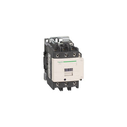
"TeSys Deca contactor, 3P(3NO) for category AC-3/AC-3e applications up to 95A @440V." It provides with 42V 50/60 Hz coil, with 1NO+1NC auxiliary contacts, power and control connections by screw clamp terminals. It procures with 4 Mcycles mechanical durability and 1.2 Mcycles electrical durability. It provides IP20 protection on front face conforming to IEC 60529. It can cover -40°C to 60°C operation temperature and without derating under 3000m altitude. Designed for demanding applications with maximum operating rates up to 3600 cycles per hour under maximum 60°C. The dimension is 127mm x 85mm x 130mm (H x W x D), mounting on rail or plate. Multi standards certified(CCC,BV,RINA,DNV-GL,LROS,CB,EAC,CSA).
Main
| Characteristic | Value(s) |
|---|---|
| Range | TeSys |
| Range of product | TeSys Deca |
| Product or component type | Contactor |
| Device short name | LC1D |
| Contactor application | Motor control Resistive load |
| Utilisation category | AC-3 AC-3e AC-4 AC-1 |
| Poles description | 3P |
| [Ue] rated operational voltage | Power circuit: <= 690 V AC 25...400 Hz |
| [Ie] rated operational current | 95 A (at <60 °C) at <= 440 V AC-3 for power circuit 125 A (at <60 °C) at <= 690 V AC-1 for power circuit 95 A (at <60 °C) at <= 440 V AC-3e for power circuit |
| [Uc] control circuit voltage | 42 V AC 50/60 Hz |
Complementary
| Characteristic | Value(s) |
|---|---|
| Motor power kW | 25 kW at 220...230 V AC 50 Hz (AC-3) 45 kW at 380...400 V AC 50 Hz (AC-3) 45 kW at 415...440 V AC 50 Hz (AC-3) 55 kW at 500 V AC 50 Hz (AC-3) 45 kW at 660...690 V AC 50 Hz (AC-3) 15 kW at 400 V AC 50 Hz (AC-4) 25 kW at 220...230 V AC 50 Hz (AC-3e) 45 kW at 380...400 V AC 50 Hz (AC-3e) 45 kW at 415...440 V AC 50 Hz (AC-3e) 55 kW at 500 V AC 50 Hz (AC-3e) 45 kW at 660...690 V AC 50 Hz (AC-3e) |
| Motor power hp | 7.5 hp at 120 V AC 60 Hz for 1 phase motors 15 hp at 230/240 V AC 60 Hz for 1 phase motors 30 hp at 200/208 V AC 60 Hz for 3 phases motors 30 hp at 230/240 V AC 60 Hz for 3 phases motors 60 hp at 460/480 V AC 60 Hz for 3 phases motors 60 hp at 575/600 V AC 60 Hz for 3 phases motors |
| Compatibility code | LC1D |
| Pole contact composition | 3 NO |
| Protective cover | With |
| [Ith] conventional free air thermal current | 10 A (at 60 °C) for signalling circuit 125 A (at 60 °C) for power circuit |
| Irms rated making capacity | 1100 A at 440 V AC for power circuit conforming to IEC 60947 140 A AC for signalling circuit conforming to IEC 60947-5-1 250 A DC for signalling circuit conforming to IEC 60947-5-1 |
| Rated breaking capacity | 1100 A at 440 V for power circuit conforming to IEC 60947 |
| [Icw] rated short-time withstand current | 1100 A 40 °C - 1 s for power circuit 800 A 40 °C - 10 s for power circuit 400 A 40 °C - 1 min for power circuit 135 A 40 °C - 10 min for power circuit 140 A - 100 ms for signalling circuit 120 A - 500 ms for signalling circuit 100 A - 1 s for signalling circuit |
| Associated fuse rating | 10 A gG for signalling circuit conforming to IEC 60947-5-1 200 A gG at <= 690 V coordination type 1 for power circuit 160 A gG at <= 690 V coordination type 2 for power circuit |
| Average impedance | 0.8 mOhm - Ith 125 A 50 Hz for power circuit |
| Power dissipation per pole | 12.5 W AC-1 7.2 W AC-3 7.2 W AC-3e |
| [Ui] rated insulation voltage | Power circuit: 1000 V conforming to IEC 60947-4-1 Power circuit: 600 V CSA certified Power circuit: 600 V UL certified Signalling circuit: 690 V conforming to IEC 60947-1 Signalling circuit: 600 V CSA certified Signalling circuit: 600 V UL certified |
| Overvoltage category | III |
| pollution degree | 3 |
| [Uimp] rated impulse withstand voltage | 8 kV conforming to IEC 60947 |
| Safety reliability level | B10d = 1.3 Mcycles contactor with nominal load conforming to EN/ISO 13849-1 B10d = 20 Mcycles contactor with mechanical load conforming to EN/ISO 13849-1 |
| Mechanical durability | 4 Mcycles |
| Electrical durability | 1.2 Mcycles 95 A AC-3 1.3 Mcycles 125 A AC-1 1.2 Mcycles 95 A AC-3e |
| Control circuit type | AC at 50/60 Hz |
| Coil technology | Without built-in suppressor module |
| Control circuit voltage limits | 0.8...1.1 Uc (-40â¦55 °C):operational AC 50 Hz 0.85...1.1 Uc (-40â¦55 °C):operational AC 60 Hz 0.3...0.6 Uc (-40â¦70 °C):drop-out AC 50/60 Hz 1...1.1 Uc (55â¦70 °C):operational AC 50/60 Hz |
| Inrush power in VA | 245 VA 60 Hz cos phi 0.75 (at 20 °C) 245 VA 50 Hz cos phi 0.75 (at 20 °C) |
| Hold-in power consumption in VA | 26 VA 60 Hz cos phi 0.3 (at 20 °C) 26 VA 50 Hz cos phi 0.3 (at 20 °C) |
| Heat dissipation | 6â¦10 W at 50/60 Hz |
| Operating time | 20...35 ms closing 6...20 ms opening |
| Maximum operating rate | 3600 cyc/h at 60 °C |
| Connections - terminals | Control circuit: screw clamp terminals 2 1â¦2.5 mm² - cable stiffness: flexible with cable end Control circuit: screw clamp terminals 1 1â¦2.5 mm² - cable stiffness: flexible with cable end Control circuit: screw clamp terminals 1 1â¦4 mm² - cable stiffness: flexible without cable end Control circuit: screw clamp terminals 2 1â¦4 mm² - cable stiffness: flexible without cable end Control circuit: screw clamp terminals 1 1â¦4 mm² - cable stiffness: solid without cable end Control circuit: screw clamp terminals 2 1â¦4 mm² - cable stiffness: solid without cable end Power circuit: connector 1 4â¦50 mm² - cable stiffness: flexible without cable end Power circuit: connector 2 4â¦25 mm² - cable stiffness: flexible without cable end Power circuit: connector 1 4â¦50 mm² - cable stiffness: flexible with cable end Power circuit: connector 2 4â¦16 mm² - cable stiffness: flexible with cable end Power circuit: connector 1 4â¦50 mm² - cable stiffness: solid without cable end Power circuit: connector 2 4â¦25 mm² - cable stiffness: solid without cable end |
| Tightening torque | Control circuit: 1.2 N.m - on screw clamp terminals - with screwdriver flat à 6 mm Control circuit: 1.2 N.m - on screw clamp terminals - with screwdriver Philips No 2 Power circuit: 12 N.m - on connector - with screwdriver flat à 6 to à 8 mm Power circuit: 12 N.m - on connector hexagonal screw head 4 mm Control circuit: 1.2 N.m - on screw clamp terminals - with screwdriver pozidriv No 2 |
| Auxiliary contact composition | 1 NO + 1 NC |
| Auxiliary contacts type | type mechanically linked 1 NO + 1 NC conforming to IEC 60947-5-1 type mirror contact 1 NC conforming to IEC 60947-4-1 |
| Signalling circuit frequency | 25...400 Hz |
| Minimum switching voltage | 17 V for signalling circuit |
| Minimum switching current | 5 mA for signalling circuit |
| Insulation resistance | > 10 MOhm for signalling circuit |
| Non-overlap time | 1.5 ms on de-energisation between NC and NO contact 1.5 ms on energisation between NC and NO contact |
| Mounting support | Plate Rail |
TeSys F contactor - 3P (3 NO) - AC-3 - <= 440 V 275 A - coil 24 V AC. Comes without coil.

Motor circuit breaker, TeSys GV4, 3P, 2A, Icu 50kA, thermal magnetic, Everlink terminals