
 1 year warranty


Material Compliance
Following EU Directive 2011/65/EU and Amendment 2015/863 July 22, 2019
Environmental
Ordering
8015644551520
1 piece
85362090
Dimensions
140 mm
205 mm
103.5 mm
3.05 kg
Container Information
1 piece
248 mm
240 mm
285 mm
3.5 kg
8015644551520
Additional Information
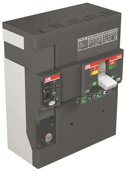
SACE Tmax T
Moulded Case Circuit Breaker
Automatic Circuit Breaker
T4
Moulded Case Circuit Breakers
F
Technical
8000 cycle
120 cycles per hour
8000 cycle
120 cycles per hour
20000 cycle
240 cycles per hour
20000 cycle
240 cycles per hour
4P
at Rated Operating Conditions per Pole 1.7 W
100 A
8 kV
1000 V
690 V AC
(220 V AC) 100 kA
(230 V AC) 100 kA
(380 V AC) 70 kA
(400 V AC) 70 kA
(415 V AC) 70 kA
(440 V AC) 65 kA
(500 V AC) 50 kA
(690 V) 40 kA
(220 V AC) 100 kA
(230 V AC) 100 kA
(380 V AC) 70 kA
(400 V AC) 70 kA
(415 V AC) 70 kA
(440 V AC) 65 kA
(500 V AC) 50 kA
(690 V) 40 kA
(220 V AC) 100 kA
(230 V AC) 100 kA
(380 V AC) 70 kA
(400 V AC) 70 kA
(415 V AC) 70 kA
(440 V AC) 65 kA
(500 V AC) 50 kA
(690 V AC) 40 kA
(220 V AC) 100 kA
(230 V AC) 100 kA
(380 V AC) 70 kA
(400 V AC) 70 kA
(415 V AC) 70 kA
(440 V AC) 65 kA
(500 V AC) 50 kA
(690 V AC) 40 kA
250 A
PR221DS-I
EL
H
IEC
T4
Fixed Circuit-Breakers
Front
Fixed Circuit-Breakers
Front
3500 V
3500 V
Certificates and Declarations
External Classifications and Standards
Q
39121100
5. Small Equipment (No External Dimension More Than 50 cm)
V11.1 : 27370409

Ordering
1 piece
85364900
Popular Downloads
Dimensions
54.9 mm
101.4 mm
106.9 mm
0.372 kg
Technical
30 ... 40 A
Auxiliary Circuit 600 V AC/DC
Main Circuit 690 V AC
Main Circuit 440 V DC
Auxiliary Circuit 600 V AC/DC
Main Circuit 690 V AC
Main Circuit 440 V DC
40 A
Auxiliary Circuit 50 Hz
Auxiliary Circuit 60 Hz
Auxiliary Circuit DC
Main Circuit 50 Hz
Main Circuit 60 Hz
Auxiliary Circuit 50 Hz
Auxiliary Circuit 60 Hz
Auxiliary Circuit DC
Main Circuit 50 Hz
Main Circuit 60 Hz
Auxiliary Circuit 6 kV
Main Circuit 8 kV
Auxiliary Circuit 6 kV
Main Circuit 8 kV
690 V
3P
1
1
3
Auxiliary Circuit NC 6 A
Auxiliary Circuit NO 4 A
Auxiliary Circuit NC 6 A
Auxiliary Circuit NO 4 A
(120 V) NC 3 A
(120 V) NO 0.5 A
(240 V) NC 3 A
(240 V) NO 0.5 A
(400 V) NC 0.75 A
(400 V) NO 0.5 A
(500 V) NC 0.75 A
(500 V) NO 0.5 A
(120 V) NC 3 A
(120 V) NO 0.5 A
(240 V) NC 3 A
(240 V) NO 0.5 A
(400 V) NC 0.75 A
(400 V) NO 0.5 A
(500 V) NC 0.75 A
(500 V) NO 0.5 A
(125 V) NC 0.55 A
(125 V) NO 0.55 A
(24 V) NC 1.25 A
(24 V) NO 1.25 A
(250 V) NC 0.27 A
(250 V) NO 0.27 A
(500 V) NC 0.15 A
(500 V) NO 0.15 A
(60 V) NC 0.55 A
(60 V) NO 0.55 A
(125 V) NC 0.55 A
(125 V) NO 0.55 A
(24 V) NC 1.25 A
(24 V) NO 1.25 A
(250 V) NC 0.27 A
(250 V) NO 0.27 A
(500 V) NC 0.15 A
(500 V) NO 0.15 A
(60 V) NC 0.55 A
(60 V) NO 0.55 A
Housing IP20
Main Circuit Terminals IP10
Housing IP20
Main Circuit Terminals IP10
3
Flexible with Ferrule 1/2x 0.75 ... 2.5 mm²
Flexible with Insulated Ferrule 1x 0.75 ... 2.5 mm²
Flexible with Insulated Ferrule 2x 0.75 ... 1.5 mm²
Flexible 1/2x 0.75 ... 1 mm²
Flexible 1/2x 1 ... 2.5 mm²
Rigid 1/2x 0.75 ... 4 mm²
Flexible with Ferrule 1/2x 0.75 ... 2.5 mm²
Flexible with Insulated Ferrule 1x 0.75 ... 2.5 mm²
Flexible with Insulated Ferrule 2x 0.75 ... 1.5 mm²
Flexible 1/2x 0.75 ... 1 mm²
Flexible 1/2x 1 ... 2.5 mm²
Rigid 1/2x 0.75 ... 4 mm²
Flexible with Ferrule 1/2x 2.5 ... 10 mm²
Flexible with Ferrule 1x 2.5 ... 35 mm²
Flexible with Insulated Ferrule 1x 2.5 ... 35 mm²
Flexible with Insulated Ferrule 1/2x 2.5 ... 10 mm²
Flexible 1/2x 2.5 ... 16 mm²
Flexible 1x 2.5 ... 35 mm²
Rigid 1/2x 2.5 ... 16 mm²
Rigid 1x 2.5 ... 35 mm²
Flexible with Ferrule 1/2x 2.5 ... 10 mm²
Flexible with Ferrule 1x 2.5 ... 35 mm²
Flexible with Insulated Ferrule 1x 2.5 ... 35 mm²
Flexible with Insulated Ferrule 1/2x 2.5 ... 10 mm²
Flexible 1/2x 2.5 ... 16 mm²
Flexible 1x 2.5 ... 35 mm²
Rigid 1/2x 2.5 ... 16 mm²
Rigid 1x 2.5 ... 35 mm²
Auxiliary Circuit 1 ... 1.2 N·m
Main Circuit 4.0 ... 4.5 N·m
Auxiliary Circuit 1 ... 1.2 N·m
Main Circuit 4.0 ... 4.5 N·m
Auxiliary Circuit 9 mm
Main Circuit 17 mm
Auxiliary Circuit 9 mm
Main Circuit 17 mm
Auxiliary Circuit Pozidriv 2
Main Circuit Pozidriv 2
Auxiliary Circuit Pozidriv 2
Main Circuit Pozidriv 2
1 ... 6
at Rated Operating Conditions per Pole 2.1 ... 3.7 W
AF40
AF52
AF65
AF40
AF52
AF65
IEC/EN 60947-1
IEC/EN 60947-4-1
IEC/EN 60947-5-1
UL 60947-1
UL 60947-4-1
IEC 60335-2-40 A2L
IEC/EN 60947-1
IEC/EN 60947-4-1
IEC/EN 60947-5-1
UL 60947-1
UL 60947-4-1
IEC 60335-2-40 A2L
Technical UL/CSA
Main Circuit 600 V AC
(NC:) B600
(NC:) Q600
(NO:) Q600
(NO:) D300
(NC:) B600
(NC:) Q600
(NO:) Q600
(NO:) D300
Flexible 1x 12-2 AWG
Flexible 2x 12-6 AWG
Stranded 1x 12-2 AWG
Stranded 2x 12-6 AWG
Flexible 1x 12-2 AWG
Flexible 2x 12-6 AWG
Stranded 1x 12-2 AWG
Stranded 2x 12-6 AWG
Flexible 1/2x 18-12 AWG
Stranded 1/2x 18-12 AWG
Flexible 1/2x 18-12 AWG
Stranded 1/2x 18-12 AWG
Auxiliary Circuit 9 ... 11 in·lb
Main Circuit 35 ... 40 in·lb
Auxiliary Circuit 9 ... 11 in·lb
Main Circuit 35 ... 40 in·lb
Environmental
Operation -40 ... +70 °C
Operation Compensated -40 ... +70 °C
Storage -50 ... +80 °C
Operation -40 ... +70 °C
Operation Compensated -40 ... +70 °C
Storage -50 ... +80 °C
Yes
2000 m
11 ms Pulse 25g
5g 3 ... 150 Hz
Following EU Directive 2011/65/EU and Amendment 2015/863 July 22, 2019
Material Compliance
Business To Business
5. Small Equipment (No External Dimension More Than 50 cm)
ABB EcoSolutions
Certificates and Declarations
Container Information
box 1 piece
123 mm
121 mm
82 mm
0.456 kg
4013614482939
12 piece
280 mm
210 mm
395 mm
5.858 kg
4013614485336
External Classifications and Standards
F
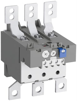
EC000106 - Thermal overload relay
EC000106 - Thermal overload relay
V11.0 : 27371501
39122330
5366 >> Thermal overload relay
3706585
4116788
3210265
Material Compliance
Environmental
Ordering
4377346
8015644518301
1 piece
85389099
Dimensions
1.85 kg
Container Information
1 piece
250 mm
170 mm
260 mm
1.95 kg
8015644518301
Additional Information
Accessories for Tmax T
Accessory
ACC
T3
SACE Tmax T
Technical
Loose or configurable
T3
4P
IEC
Certificates and Declarations
External Classifications and Standards
Q
39121100
5. Small Equipment (No External Dimension More Than 50 cm)
Ordering
1 piece
85364900
Popular Downloads
Dimensions
104 mm
151 mm
126 mm
0.76 kg
Technical
100 ... 135 A
Auxiliary Circuit 440 V DC
Auxiliary Circuit 500 V AC
Main Circuit 690 V AC
Main Circuit 440 V DC
Auxiliary Circuit 440 V DC
Auxiliary Circuit 500 V AC
Main Circuit 690 V AC
Main Circuit 440 V DC
135 A
Auxiliary Circuit 50 Hz
Auxiliary Circuit 60 Hz
Auxiliary Circuit DC
Main Circuit 60 Hz
Main Circuit 50 Hz
Main Circuit DC
Auxiliary Circuit 50 Hz
Auxiliary Circuit 60 Hz
Auxiliary Circuit DC
Main Circuit 60 Hz
Main Circuit 50 Hz
Main Circuit DC
Auxiliary Circuit 6 kV
Main Circuit 6 kV
Auxiliary Circuit 6 kV
Main Circuit 6 kV
690 V
3P
1
1
3
Auxiliary Circuit NC 5 A
Auxiliary Circuit NO 5 A
Auxiliary Circuit NC 5 A
Auxiliary Circuit NO 5 A
(120 V) NC 3 A
(120 V) NO 1.5 A
(240 V) NC 3 A
(240 V) NO 1.2 A
(400 V) NC 0.75 A
(400 V) NO 0.37 A
(440 V) NC 0.75 A
(440 V) NO 0.37 A
(500 V) NC 0.3 A
(500 V) NO 0.25 A
(120 V) NC 3 A
(120 V) NO 1.5 A
(240 V) NC 3 A
(240 V) NO 1.2 A
(400 V) NC 0.75 A
(400 V) NO 0.37 A
(440 V) NC 0.75 A
(440 V) NO 0.37 A
(500 V) NC 0.3 A
(500 V) NO 0.25 A
(125 V) NC 0.25 A
(125 V) NO 0.25 A
(24 V) NC 1.25 A
(24 V) NO 1.25 A
(250 V) NC 0.12 A
(250 V) NO 0.04 A
(60 V) NC 0.25 A
(60 V) NO 0.25 A
(125 V) NC 0.25 A
(125 V) NO 0.25 A
(24 V) NC 1.25 A
(24 V) NO 1.25 A
(250 V) NC 0.12 A
(250 V) NO 0.04 A
(60 V) NC 0.25 A
(60 V) NO 0.25 A
Housing IP20
Main Circuit Terminals IP00
Housing IP20
Main Circuit Terminals IP00
3
Flexible with Ferrule 1/2x 0.75 ... 2.5 mm²
Flexible 1/2x 0.75 ... 2.5 mm²
Rigid 1/2x 0.75 ... 4 mm²
Flexible with Ferrule 1/2x 0.75 ... 2.5 mm²
Flexible 1/2x 0.75 ... 2.5 mm²
Rigid 1/2x 0.75 ... 4 mm²
Hole Diameter > 10 mm²
Rigid or Flexible with Cable Lug 1x 25 ... 120 mm²
Hole Diameter > 10 mm²
Rigid or Flexible with Cable Lug 1x 25 ... 120 mm²
Auxiliary Circuit 1 ... 1.3 N·m
Main Circuit 25 N·m
Auxiliary Circuit 1 ... 1.3 N·m
Main Circuit 25 N·m
Auxiliary Circuit 9 mm
Auxiliary Circuit Pozidriv 1
Main Circuit Open Bars
Auxiliary Circuit Pozidriv 1
Main Circuit Open Bars
1 ... 6
at Rated Operating Conditions per Pole 3.3 ... 6.0 W
A145
A185
AF145
AF185
AF190
AF205
A145
A185
AF145
AF185
AF190
AF205
IEC/EN 60947-1
IEC/EN 60947-4-1
IEC/EN 60947-5-1
UL 60947-1
UL 60947-4-1
IEC/EN 60947-1
IEC/EN 60947-4-1
IEC/EN 60947-5-1
UL 60947-1
UL 60947-4-1
Technical UL/CSA
Main Circuit 600 V AC
(NC:) B600
(NO:) C600
(NC:) B600
(NO:) C600
Flexible 1x 4-0000 AWG
Stranded 1x 4-0000 AWG
Flexible 1x 4-0000 AWG
Stranded 1x 4-0000 AWG
Flexible 1/2x 18-14 AWG
Stranded 1/2x 18-14 AWG
Flexible 1/2x 18-14 AWG
Stranded 1/2x 18-14 AWG
Auxiliary Circuit 12 in·lb
Main Circuit 220 in·lb
Auxiliary Circuit 12 in·lb
Main Circuit 220 in·lb
Environmental
Operation -25 ... +55 °C
Operation Compensated -25 ... +55 °C
Storage -40 ... +70 °C
Operation -25 ... +55 °C
Operation Compensated -25 ... +55 °C
Storage -40 ... +70 °C
Yes
2000 m
11 ms Pulse 12g
Following EU Directive 2011/65/EU and Amendment 2015/863 July 22, 2019
Material Compliance
Business To Business
5. Small Equipment (No External Dimension More Than 50 cm)
ABB EcoSolutions
Certificates and Declarations
Container Information
box 1 piece
165 mm
133 mm
151 mm
1.01 kg
4013614286032
4 piece
280 mm
210 mm
395 mm
8.786 kg
4013614494253
External Classifications and Standards
F
EC000106 - Thermal overload relay
EC000106 - Thermal overload relay
V11.0 : 27371501
39122330
5366 >> Thermal overload relay
3709359
3228704
Ordering
1 piece
85364900
Popular Downloads
Dimensions
45 mm
139.5 mm
86 mm
0.54 kg
Technical
3
0
2
2
3P
IEC/EN 60947-1, IEC/EN 60947-4-1, UL 60335-2-40 LZGH2 A2L, UL 60947-4-1, CSA C22.2 No. 60335-2-40 LZGH2 A2L, CSA C22.2 No. 60947-4-1
Auxiliary Circuit 690 V
Main Circuit 690 V
Auxiliary Circuit 690 V
Main Circuit 690 V
Auxiliary Circuit 50 / 60 Hz
Main Circuit 50 / 60 Hz
Auxiliary Circuit 50 / 60 Hz
Main Circuit 50 / 60 Hz
acc. to IEC 60947-4-1, Open Contactors Θ = 40 °C 50 A
acc. to IEC 60947-5-1, Θ = 40 °C 16 A
acc. to IEC 60947-4-1, Open Contactors Θ = 40 °C 50 A
acc. to IEC 60947-5-1, Θ = 40 °C 16 A
(690 V) 40 °C 50 A
(690 V) 60 °C 42 A
(690 V) 70 °C 37 A
(690 V) 40 °C 50 A
(690 V) 60 °C 42 A
(690 V) 70 °C 37 A
(415 V) 60 °C 38 A
(440 V) 60 °C 38 A
(500 V) 60 °C 33 A
(690 V) 60 °C 24 A
(380 / 400 V) 60 °C 38 A
(220 / 230 / 240 V) 60 °C 40 A
(415 V) 60 °C 38 A
(440 V) 60 °C 38 A
(500 V) 60 °C 33 A
(690 V) 60 °C 24 A
(380 / 400 V) 60 °C 38 A
(220 / 230 / 240 V) 60 °C 40 A
(415 V) 60 °C 38 A
(440 V) 60 °C 38 A
(500 V) 60 °C 33 A
(690 V) 60 °C 24 A
(380 / 400 V) 60 °C 38 A
(220 / 230 / 240 V) 60 °C 40 A
(415 V) 60 °C 38 A
(440 V) 60 °C 38 A
(500 V) 60 °C 33 A
(690 V) 60 °C 24 A
(380 / 400 V) 60 °C 38 A
(220 / 230 / 240 V) 60 °C 40 A
(500 V) 2 A
(690 V) 2 A
(24 / 127 V) 6 A
(220 / 240 V) 4 A
(400 / 440 V) 3 A
(500 V) 2 A
(690 V) 2 A
(24 / 127 V) 6 A
(220 / 240 V) 4 A
(400 / 440 V) 3 A
(110 V) 2 Poles in Series, 40 °C 50 A
(110 V) 2 Poles in Series, 60 °C 42 A
(110 V) 2 Poles in Series, 70 °C 37 A
(110 V) 3 Poles in Series, 40 °C 50 A
(110 V) 3 Poles in Series, 60 °C 42 A
(110 V) 3 Poles in Series, 70 °C 37 A
(220 V) 3 Poles in Series, 40 °C 50 A
(220 V) 3 Poles in Series, 60 °C 42 A
(220 V) 3 Poles in Series, 70 °C 37 A
(72 V) 1-Pole, 40 °C 50 A
(72 V) 1-Pole, 60 °C 42 A
(72 V) 1-Pole, 70 °C 37 A
(72 V) 2 Poles in Series, 40 °C 50 A
(72 V) 2 Poles in Series, 60 °C 42 A
(72 V) 2 Poles in Series, 70 °C 37 A
(72 V) 3 Poles in Series, 40 °C 50 A
(72 V) 3 Poles in Series, 60 °C 42 A
(72 V) 3 Poles in Series, 70 °C 37 A
(110 V) 2 Poles in Series, 40 °C 50 A
(110 V) 2 Poles in Series, 60 °C 42 A
(110 V) 2 Poles in Series, 70 °C 37 A
(110 V) 3 Poles in Series, 40 °C 50 A
(110 V) 3 Poles in Series, 60 °C 42 A
(110 V) 3 Poles in Series, 70 °C 37 A
(220 V) 3 Poles in Series, 40 °C 50 A
(220 V) 3 Poles in Series, 60 °C 42 A
(220 V) 3 Poles in Series, 70 °C 37 A
(72 V) 1-Pole, 40 °C 50 A
(72 V) 1-Pole, 60 °C 42 A
(72 V) 1-Pole, 70 °C 37 A
(72 V) 2 Poles in Series, 40 °C 50 A
(72 V) 2 Poles in Series, 60 °C 42 A
(72 V) 2 Poles in Series, 70 °C 37 A
(72 V) 3 Poles in Series, 40 °C 50 A
(72 V) 3 Poles in Series, 60 °C 42 A
(72 V) 3 Poles in Series, 70 °C 37 A
(110 V) 2 Poles in Series, 40 °C 50 A
(110 V) 2 Poles in Series, 60 °C 42 A
(110 V) 2 Poles in Series, 70 °C 37 A
(110 V) 3 Poles in Series, 40 °C 50 A
(110 V) 3 Poles in Series, 60 °C 42 A
(110 V) 3 Poles in Series, 70 °C 37 A
(220 V) 3 Poles in Series, 40 °C 50 A
(220 V) 3 Poles in Series, 60 °C 42 A
(220 V) 3 Poles in Series, 70 °C 37 A
(72 V) 1-Pole, 40 °C 50 A
(110 V) 2 Poles in Series, 40 °C 50 A
(110 V) 2 Poles in Series, 60 °C 42 A
(110 V) 2 Poles in Series, 70 °C 37 A
(110 V) 3 Poles in Series, 40 °C 50 A
(110 V) 3 Poles in Series, 60 °C 42 A
(110 V) 3 Poles in Series, 70 °C 37 A
(220 V) 3 Poles in Series, 40 °C 25 A
(220 V) 3 Poles in Series, 60 °C 25 A
(220 V) 3 Poles in Series, 70 °C 25 A
(72 V) 1-Pole, 40 °C 25 A
(72 V) 1-Pole, 60 °C 25 A
(72 V) 1-Pole, 70 °C 25 A
(72 V) 2 Poles in Series, 40 °C 50 A
(72 V) 2 Poles in Series, 60 °C 42 A
(72 V) 2 Poles in Series, 70 °C 37 A
(72 V) 3 Poles in Series, 40 °C 50 A
(72 V) 3 Poles in Series, 60 °C 42 A
(72 V) 3 Poles in Series, 70 °C 37 A
(110 V) 2 Poles in Series, 40 °C 50 A
(110 V) 2 Poles in Series, 60 °C 42 A
(110 V) 2 Poles in Series, 70 °C 37 A
(110 V) 3 Poles in Series, 40 °C 50 A
(110 V) 3 Poles in Series, 60 °C 42 A
(110 V) 3 Poles in Series, 70 °C 37 A
(220 V) 3 Poles in Series, 40 °C 25 A
(220 V) 3 Poles in Series, 60 °C 25 A
(220 V) 3 Poles in Series, 70 °C 25 A
(72 V) 1-Pole, 40 °C 25 A
(24 V) 6 A / 144 W
(48 V) 2.8 A / 134 W
(72 V) 1 A / 72 W
(110 V) 0.55 A / 60 W
(125 V) 0.55 A / 69 W
(220 V) 0.27 A / 60 W
(250 V) 0.27 A / 68 W
(400 V) 0.15 A / 60 W
(500 V) 0.13 A / 65 W
(600 V) 0.1 A / 60 W
(24 V) 6 A / 144 W
(48 V) 2.8 A / 134 W
(72 V) 1 A / 72 W
(110 V) 0.55 A / 60 W
(125 V) 0.55 A / 69 W
(220 V) 0.27 A / 60 W
(250 V) 0.27 A / 68 W
(400 V) 0.15 A / 60 W
(500 V) 0.13 A / 65 W
(600 V) 0.1 A / 60 W
(400 V) 18.5 kW
(415 V) 18.5 kW
(440 V) 22 kW
(500 V) 22 kW
(690 V) 22 kW
(380 / 400 V) 18.5 kW
(220 / 230 / 240 V) 11 kW
(400 V) 18.5 kW
(415 V) 18.5 kW
(440 V) 22 kW
(500 V) 22 kW
(690 V) 22 kW
(380 / 400 V) 18.5 kW
(220 / 230 / 240 V) 11 kW
(415 V) 18.5 kW
(440 V) 22 kW
(500 V) 22 kW
(690 V) 22 kW
(380 / 400 V) 18.5 kW
(220 / 230 / 240 V) 11 kW
(415 V) 18.5 kW
(440 V) 22 kW
(500 V) 22 kW
(690 V) 22 kW
(380 / 400 V) 18.5 kW
(220 / 230 / 240 V) 11 kW
at 40 °C Ambient Temp, in Free Air, from a Cold State 10 s 350 A
at 40 °C Ambient Temp, in Free Air, from a Cold State 15 min 50 A
at 40 °C Ambient Temp, in Free Air, from a Cold State 1 min 150 A
at 40 °C Ambient Temp, in Free Air, from a Cold State 1 s 700 A
at 40 °C Ambient Temp, in Free Air, from a Cold State 30 s 225 A
for 0.1 s 140 A
for 1 s 100 A
cos phi=0.45 (cos phi=0.35 for Ie > 100 A) at 440 V 500 A
cos phi=0.45 (cos phi=0.35 for Ie > 100 A) at 690 V 200 A
cos phi=0.45 (cos phi=0.35 for Ie > 100 A) at 440 V 500 A
cos phi=0.45 (cos phi=0.35 for Ie > 100 A) at 690 V 200 A
acc. to IEC 60947-4-1 690 V
acc. to IEC 60947-5-1 690 V
acc. to UL/CSA 600 V
acc. to IEC 60947-4-1 690 V
acc. to IEC 60947-5-1 690 V
acc. to UL/CSA 600 V
6 kV
(AC-1) 600 cycles per hour
(AC-15) 1200 cycles per hour
(AC-2 / AC-4) 150 cycles per hour
(AC-3) 1200 cycles per hour
(DC-13) 900 cycles per hour
(AC-1) 600 cycles per hour
(AC-15) 1200 cycles per hour
(AC-2 / AC-4) 150 cycles per hour
(AC-3) 1200 cycles per hour
(DC-13) 900 cycles per hour
3600 cycles per hour
DC Operation 24 V
at 6 A per Pole 0.1 W
at Rated Operating Conditions AC-1 per Pole 2.4 W
at Rated Operating Conditions AC-3 per Pole 1.3 W
at 6 A per Pole 0.1 W
at Rated Operating Conditions AC-1 per Pole 2.4 W
at Rated Operating Conditions AC-3 per Pole 1.3 W
Between Coil De-energization and NC Contact Closing 22 ... 57 ms
Between Coil De-energization and NO Contact Opening 17 ... 29 ms
Between Coil Energization and NC Contact Opening 20 ... 35 ms
Between Coil Energization and NO Contact Closing 27 ... 53 ms
Between Coil De-energization and NC Contact Closing 22 ... 57 ms
Between Coil De-energization and NO Contact Opening 17 ... 29 ms
Between Coil Energization and NC Contact Opening 20 ... 35 ms
Between Coil Energization and NO Contact Closing 27 ... 53 ms
TH35-15 (35 x 15 mm Mounting Rail) acc. to IEC 60715
TH35-7.5 (35 x 7.5 mm Mounting Rail) acc. to IEC 60715
TH35-15 (35 x 15 mm Mounting Rail) acc. to IEC 60715
TH35-7.5 (35 x 7.5 mm Mounting Rail) acc. to IEC 60715
2 x M4 Screws Placed Diagonally
Flexible with Ferrule 1/2x 1.5 ... 10 mm²
Flexible with Insulated Ferrule 1x 1.5 ... 10 mm²
Flexible with Insulated Ferrule 2x 1.5 ... 4 mm²
Rigid Solid 1/2x 2.5 ... 4 mm²
Rigid Stranded 1/2x 2.5 ... 10 mm²
Flexible with Ferrule 1/2x 1.5 ... 10 mm²
Flexible with Insulated Ferrule 1x 1.5 ... 10 mm²
Flexible with Insulated Ferrule 2x 1.5 ... 4 mm²
Rigid Solid 1/2x 2.5 ... 4 mm²
Rigid Stranded 1/2x 2.5 ... 10 mm²
Flexible with Ferrule 1/2x 0.75 ... 2.5 mm²
Flexible with Insulated Ferrule 1x 0.75 ... 2.5 mm²
Flexible with Insulated Ferrule 2x 0.75 ... 1.5 mm²
Rigid Solid 1/2x 1 ... 2.5 mm²
Rigid Stranded 1/2x 1 ... 2.5 mm²
Flexible with Ferrule 1/2x 0.75 ... 2.5 mm²
Flexible with Insulated Ferrule 1x 0.75 ... 2.5 mm²
Flexible with Insulated Ferrule 2x 0.75 ... 1.5 mm²
Rigid Solid 1/2x 1 ... 2.5 mm²
Rigid Stranded 1/2x 1 ... 2.5 mm²
Flexible with Ferrule 1/2x 0.75 ... 2.5 mm²
Flexible with Insulated Ferrule 1x 0.75 ... 2.5 mm²
Flexible with Insulated Ferrule 2x 0.75 ... 1.5 mm²
Rigid Solid 1/2x 1 ... 2.5 mm²
Rigid Stranded 1/2x 1 ... 2.5 mm²
Flexible with Ferrule 1/2x 0.75 ... 2.5 mm²
Flexible with Insulated Ferrule 1x 0.75 ... 2.5 mm²
Flexible with Insulated Ferrule 2x 0.75 ... 1.5 mm²
Rigid Solid 1/2x 1 ... 2.5 mm²
Rigid Stranded 1/2x 1 ... 2.5 mm²
Auxiliary Circuit 10 mm
Control Circuit 10 mm
Main Circuit 14 mm
Auxiliary Circuit 10 mm
Control Circuit 10 mm
Main Circuit 14 mm
acc. to IEC 60529, IEC 60947-1, EN 60529 Auxiliary Terminals IP20
acc. to IEC 60529, IEC 60947-1, EN 60529 Coil Terminals IP20
acc. to IEC 60529, IEC 60947-1, EN 60529 Main Terminals IP20
acc. to IEC 60529, IEC 60947-1, EN 60529 Auxiliary Terminals IP20
acc. to IEC 60529, IEC 60947-1, EN 60529 Coil Terminals IP20
acc. to IEC 60529, IEC 60947-1, EN 60529 Main Terminals IP20
Auxiliary Circuit 1.2 N·m
Control Circuit 1.2 N·m
Main Circuit 2.5 N·m
Auxiliary Circuit 1.2 N·m
Control Circuit 1.2 N·m
Main Circuit 2.5 N·m
Screw Terminals
Block Contactor
Technical UL/CSA
Main Circuit 600 V
(600 V AC) 50 A
(120 V AC) Single Phase 2 hp
(200 ... 208 V AC) Three Phase 10 hp
(220 ... 240 V AC) Three Phase 10 hp
(240 V AC) Single Phase 5 hp
(440 ... 480 V AC) Three Phase 25 hp
(550 ... 600 V AC) Three Phase 30 hp
(120 V AC) Single Phase 2 hp
(200 ... 208 V AC) Three Phase 10 hp
(220 ... 240 V AC) Three Phase 10 hp
(240 V AC) Single Phase 5 hp
(440 ... 480 V AC) Three Phase 25 hp
(550 ... 600 V AC) Three Phase 30 hp
Rigid Solid 1/2x 14-10 AWG
Rigid Stranded 1/2x 14-8 AWG
Rigid Solid 1/2x 14-10 AWG
Rigid Stranded 1/2x 14-8 AWG
Rigid Solid 1/2x 18-14 AWG
Rigid Stranded 1/2x 18-14 AWG
Rigid Solid 1/2x 18-14 AWG
Rigid Stranded 1/2x 18-14 AWG
Rigid Solid 1/2x 18-14 AWG
Rigid Stranded 1/2x 18-14 AWG
Rigid Solid 1/2x 18-14 AWG
Rigid Stranded 1/2x 18-14 AWG
Auxiliary Circuit 11 in·lb
Control Circuit 11 in·lb
Main Circuit 22 in·lb
Auxiliary Circuit 11 in·lb
Control Circuit 11 in·lb
Main Circuit 22 in·lb
(120 V AC) Single Phase 24 A
(200 ... 208 V AC) Three Phase 32.2 A
(220 ... 240 V AC) Three Phase 28 A
(240 V AC) Single Phase 28 A
(440 ... 480 V AC) Three Phase 34 A
(550 ... 600 V AC) Three Phase 32 A
(120 V AC) Single Phase 24 A
(200 ... 208 V AC) Three Phase 32.2 A
(220 ... 240 V AC) Three Phase 28 A
(240 V AC) Single Phase 28 A
(440 ... 480 V AC) Three Phase 34 A
(550 ... 600 V AC) Three Phase 32 A
Environmental
Close to Contactor Fitted with Thermal O/L Relay -25 ... 60 °C
Close to Contactor without Thermal O/L Relay -40 ... 70 °C
Close to Contactor for Storage -60 ... +80 °C
Close to Contactor Fitted with Thermal O/L Relay -25 ... 60 °C
Close to Contactor without Thermal O/L Relay -40 ... 70 °C
Close to Contactor for Storage -60 ... +80 °C
Category B according to IEC 60947-1 Annex Q
Without Derating 3000 m
Closed, Shock Direction: A 30 g
Closed, Shock Direction: B1 25 g
Closed, Shock Direction: B2 15 g
Closed, Shock Direction: C1 25 g
Closed, Shock Direction: C2 25 g
Closed, Shock Direction: A 30 g
Closed, Shock Direction: B1 25 g
Closed, Shock Direction: B2 15 g
Closed, Shock Direction: C1 25 g
Closed, Shock Direction: C2 25 g
4g Closed Position & 2g Open position 5 ... 300 Hz
3
Material Compliance
Business To Business
5. Small Equipment (No External Dimension More Than 50 cm)
ABB EcoSolutions
Recycled Cardboard - 86 %
Recycled Metal - 28 %
Certificates and Declarations
Container Information
box 1 piece
96 mm
145 mm
50 mm
0.591 kg
3471523158696
crate 12 piece
51 mm
98 mm
148 mm
7.092 kg
External Classifications and Standards
Q
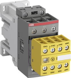
EC000066 - Power contactor, AC switching
EC000066 - Power contactor, AC switching
EC000066 - Power contactor, AC switching
V11.0 : 27371003
39121529
4758 >> Iec Contactors
3708050
3210682

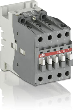
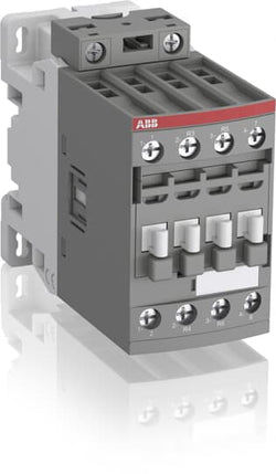
A30-30-10 190V 50Hz / 220V 60Hz Contactor

A40-30-01 110V 50Hz / 110-120V 60Hz Contactor

A30-30-01 24V 50Hz / 24V 60Hz Contactor

A40-30-01 24V 50Hz / 24V 60Hz Contactor
A30-30-10 690V60HZ Contactor

Ordering
1 piece
85364900
Popular Downloads
Dimensions
54 mm
141 mm
130 mm
0.81 kg
Technical
3
0
1
0
3P
IEC/EN 60947-1, IEC/EN 60947-4-1
Auxiliary Circuit 690 V
Main Circuit 690 V
Auxiliary Circuit 690 V
Main Circuit 690 V
Auxiliary Circuit 50 / 60 Hz
Control Circuit 50 / 60 Hz
Main Circuit 50 / 60 Hz
Auxiliary Circuit 50 / 60 Hz
Control Circuit 50 / 60 Hz
Main Circuit 50 / 60 Hz
acc. to IEC 60947-5-1, Θ = 40 °C 16 A
(500 V) 2 A
(690 V) 2 A
(24 / 127 V) 6 A
(220 / 240 V) 4 A
(380 / 400 V) 3 A
(500 V) 2 A
(690 V) 2 A
(24 / 127 V) 6 A
(220 / 240 V) 4 A
(380 / 400 V) 3 A
(24 V) 6 A / 144 W
(48 V) 2.8 A / 134 W
(72 V) 2 / 144 W
(110 V) 0.55 A / 60 W
(125 V) 1.1 / 138 W
(220 V) 0.55 A / 121 W
(250 V) 0.55 / 138 W
(24 V) 6 A / 144 W
(48 V) 2.8 A / 134 W
(72 V) 2 / 144 W
(110 V) 0.55 A / 60 W
(125 V) 1.1 / 138 W
(220 V) 0.55 A / 121 W
(250 V) 0.55 / 138 W
(230 / 240 V) 40 °C, 50 / 60 Hz 16 kvar
(230 / 240 V) 55 °C, 50 / 60 Hz 16 kvar
(230 / 240 V) 70 °C, 50 / 60 Hz 11 kvar
(400 / 415 V) 40 °C, 50 / 60 Hz 30 kvar
(400 / 415 V) 70 °C, 50 / 60 Hz 19.5 kvar
(400 / 415 V) 55 °C, 50 / 60 Hz 27.5 kvar
(440 V) 40 °C, 50 / 60 Hz 32 kvar
(440 V) 55 °C, 50 / 60 Hz 30 kvar
(440 V) 70 °C, 50 / 60 Hz 20.5 kvar
(500 / 550 V), 40 °C, 50 / 60 Hz 34 kvar
(500 / 550 V) 55 °C, 50 / 60 Hz 34 kvar
(500 / 550 V) 70 °C, 50 / 60 Hz 25 kvar
(690 V) 40 °C, 50 / 60 Hz 45 kvar
(690 V) 55 °C, 50 / 60 Hz 45 kvar
(690 V) 70 °C, 50 / 60 Hz 32 kvar
(230 / 240 V) 40 °C, 50 / 60 Hz 16 kvar
(230 / 240 V) 55 °C, 50 / 60 Hz 16 kvar
(230 / 240 V) 70 °C, 50 / 60 Hz 11 kvar
(400 / 415 V) 40 °C, 50 / 60 Hz 30 kvar
(400 / 415 V) 70 °C, 50 / 60 Hz 19.5 kvar
(400 / 415 V) 55 °C, 50 / 60 Hz 27.5 kvar
(440 V) 40 °C, 50 / 60 Hz 32 kvar
(440 V) 55 °C, 50 / 60 Hz 30 kvar
(440 V) 70 °C, 50 / 60 Hz 20.5 kvar
(500 / 550 V), 40 °C, 50 / 60 Hz 34 kvar
Auxiliary Circuit - gG Type Fuses 10 A
gG Type Fuses 200 A
Auxiliary Circuit - gG Type Fuses 10 A
gG Type Fuses 200 A
for 0.1 s 140 A
for 1 s 100 A
for 0.1 s 140 A
for 1 s 100 A
cos phi=0.45 (cos phi=0.35 for Ie > 100 A) at 440 V 820 A
cos phi=0.45 (cos phi=0.35 for Ie > 100 A) at 690 V 340 A
cos phi=0.45 (cos phi=0.35 for Ie > 100 A) at 440 V 820 A
cos phi=0.45 (cos phi=0.35 for Ie > 100 A) at 690 V 340 A
acc. to IEC 60947-4-1 1000 V
acc. to IEC 60947-5-1 690 V
acc. to UL/CSA 600 V
acc. to IEC 60947-4-1 1000 V
acc. to IEC 60947-5-1 690 V
acc. to UL/CSA 600 V
8 kV
Ue =< 440 V 250000 cycle
Ue = 500 ... 690 V 100000 cycle
Ue =< 440 V 250000 cycle
Ue = 500 ... 690 V 100000 cycle
240 cycles per hour
17 / 5 VLT4K
50 Hz 220 ... 230 V
60 Hz 230 ... 240 V
50 Hz 220 ... 230 V
60 Hz 230 ... 240 V
Average Holding Value 50 / 60 Hz 12 V·A
Average Holding Value 50 Hz 12 V·A
Average Holding Value 60 Hz 12 V·A
Average Pull-in Value 50 Hz 120 V·A
Average Pull-in Value 60 Hz 140 V·A
Average Holding Value 50 / 60 Hz 12 V·A
Average Holding Value 50 Hz 12 V·A
Average Holding Value 60 Hz 12 V·A
Average Pull-in Value 50 Hz 120 V·A
Average Pull-in Value 60 Hz 140 V·A
at Rated Operating Conditions per Pole 0.1 W
at 6 A per Pole 0.1 W
at Rated Operating Conditions per Pole 0.1 W
at 6 A per Pole 0.1 W
Between Coil De-energization and NO Contact Opening 4 ... 11 ms
Between Coil Energization and NO Contact Closing 8 ... 21 ms
Between Coil De-energization and NO Contact Opening 4 ... 11 ms
Between Coil Energization and NO Contact Closing 8 ... 21 ms
TH35-15 (35 x 15 mm Mounting Rail) acc. to IEC 60715
TH35-7.5 (35 x 7.5 mm Mounting Rail) acc. to IEC 60715
TH35-15 (35 x 15 mm Mounting Rail) acc. to IEC 60715
TH35-7.5 (35 x 7.5 mm Mounting Rail) acc. to IEC 60715
2 x M4 Screws Placed Diagonally
Flexible with Cable End 2.5 ... 4 mm²
Rigid Cable 2.5 ... 6 mm²
Flexible with Cable End 2.5 ... 4 mm²
Rigid Cable 2.5 ... 6 mm²
Flexible with Cable End 0.75 ... 2.5 mm²
Rigid Cable 1 ... 4 mm²
Flexible with Cable End 0.75 ... 2.5 mm²
Rigid Cable 1 ... 4 mm²
acc. to IEC 60529, IEC 60947-1, EN 60529 Auxiliary Terminals IP20
acc. to IEC 60529, IEC 60947-1, EN 60529 Coil Terminals IP20
acc. to IEC 60529, IEC 60947-1, EN 60529 Main Terminals IP20
acc. to IEC 60529, IEC 60947-1, EN 60529 Auxiliary Terminals IP20
acc. to IEC 60529, IEC 60947-1, EN 60529 Coil Terminals IP20
acc. to IEC 60529, IEC 60947-1, EN 60529 Main Terminals IP20
M 5 (+,-) pozidriv 2 screws with 2x (5.6x6.5 mm) connector
Screw Terminals
Block Contactor
Environmental
Close to Contactor for Storage -60 ... +80 °C
Near Contactor for Operation in Free Air (0.85 ... 1.1 Uc) -40 ... +55 °C
Near Contactor for Operation in Free Air (Uc) -40 ... 70 °C
Close to Contactor for Storage -60 ... +80 °C
Near Contactor for Operation in Free Air (0.85 ... 1.1 Uc) -40 ... +55 °C
Near Contactor for Operation in Free Air (Uc) -40 ... 70 °C
acc. to IEC 60068-2-30 and 60068-2-11 - UTE C 63-100 specification II
Without Derating 3000 m
3
Material Compliance
Following EU Directive 2011/65/EU and Amendment 2015/863 July 22, 2019
Business To Business
5. Small Equipment (No External Dimension More Than 50 cm)
Certificates and Declarations
Container Information
box 1 piece
135 mm
155 mm
63 mm
0.81 kg
3471522302809
External Classifications and Standards
Q
EC001079 - Capacitor contactor
EC001079 - Capacitor contactor
EC001079 - Capacitor contactor
V11.0 : 27371006
39121529
4756 >> Capacitor magnet contactor
3709165

Ordering
1 piece
85364900
Popular Downloads
Dimensions
45 mm
119.5 mm
86 mm
0.36 kg
Technical
3
0
2
2
3P
IEC/EN 60947-1, IEC/EN 60947-4-1, UL 60335-2-40 LZGH2 A2L, UL 60947-4-1, CSA C22.2 No. 60335-2-40 LZGH2 A2L, CSA C22.2 No. 60947-4-1
Auxiliary Circuit 690 V
Main Circuit 690 V
Auxiliary Circuit 690 V
Main Circuit 690 V
Auxiliary Circuit 50 / 60 Hz
Control Circuit 50 / 60 Hz
Main Circuit 50 / 60 Hz
Auxiliary Circuit 50 / 60 Hz
Control Circuit 50 / 60 Hz
Main Circuit 50 / 60 Hz
acc. to IEC 60947-4-1, Open Contactors Θ = 40 °C 50 A
acc. to IEC 60947-5-1, Θ = 40 °C 16 A
acc. to IEC 60947-4-1, Open Contactors Θ = 40 °C 50 A
acc. to IEC 60947-5-1, Θ = 40 °C 16 A
(690 V) 40 °C 50 A
(690 V) 60 °C 42 A
(690 V) 70 °C 37 A
(690 V) 40 °C 50 A
(690 V) 60 °C 42 A
(690 V) 70 °C 37 A
(415 V) 60 °C 38 A
(440 V) 60 °C 38 A
(500 V) 60 °C 33 A
(690 V) 60 °C 24 A
(380 / 400 V) 60 °C 38 A
(220 / 230 / 240 V) 60 °C 40 A
(415 V) 60 °C 38 A
(440 V) 60 °C 38 A
(500 V) 60 °C 33 A
(690 V) 60 °C 24 A
(380 / 400 V) 60 °C 38 A
(220 / 230 / 240 V) 60 °C 40 A
(415 V) 60 °C 38 A
(440 V) 60 °C 38 A
(500 V) 60 °C 33 A
(690 V) 60 °C 24 A
(380 / 400 V) 60 °C 38 A
(220 / 230 / 240 V) 60 °C 40 A
(415 V) 60 °C 38 A
(440 V) 60 °C 38 A
(500 V) 60 °C 33 A
(690 V) 60 °C 24 A
(380 / 400 V) 60 °C 38 A
(220 / 230 / 240 V) 60 °C 40 A
(500 V) 2 A
(690 V) 2 A
(24 / 127 V) 6 A
(220 / 240 V) 4 A
(400 / 440 V) 3 A
(500 V) 2 A
(690 V) 2 A
(24 / 127 V) 6 A
(220 / 240 V) 4 A
(400 / 440 V) 3 A
(110 V) 2 Poles in Series, 40 °C 50 A
(110 V) 2 Poles in Series, 60 °C 42 A
(110 V) 2 Poles in Series, 70 °C 37 A
(110 V) 3 Poles in Series, 40 °C 50 A
(110 V) 3 Poles in Series, 60 °C 42 A
(110 V) 3 Poles in Series, 70 °C 37 A
(220 V) 3 Poles in Series, 40 °C 50 A
(220 V) 3 Poles in Series, 60 °C 42 A
(220 V) 3 Poles in Series, 70 °C 37 A
(72 V) 1-Pole, 40 °C 50 A
(72 V) 1-Pole, 60 °C 42 A
(72 V) 1-Pole, 70 °C 37 A
(72 V) 2 Poles in Series, 40 °C 50 A
(72 V) 2 Poles in Series, 60 °C 42 A
(72 V) 2 Poles in Series, 70 °C 37 A
(72 V) 3 Poles in Series, 40 °C 50 A
(72 V) 3 Poles in Series, 60 °C 42 A
(72 V) 3 Poles in Series, 70 °C 37 A
(110 V) 2 Poles in Series, 40 °C 50 A
(110 V) 2 Poles in Series, 60 °C 42 A
(110 V) 2 Poles in Series, 70 °C 37 A
(110 V) 3 Poles in Series, 40 °C 50 A
(110 V) 3 Poles in Series, 60 °C 42 A
(110 V) 3 Poles in Series, 70 °C 37 A
(220 V) 3 Poles in Series, 40 °C 50 A
(220 V) 3 Poles in Series, 60 °C 42 A
(220 V) 3 Poles in Series, 70 °C 37 A
(72 V) 1-Pole, 40 °C 50 A
(110 V) 2 Poles in Series, 40 °C 50 A
(110 V) 2 Poles in Series, 60 °C 42 A
(110 V) 2 Poles in Series, 70 °C 37 A
(110 V) 3 Poles in Series, 40 °C 50 A
(110 V) 3 Poles in Series, 60 °C 42 A
(110 V) 3 Poles in Series, 70 °C 37 A
(220 V) 3 Poles in Series, 40 °C 50 A
(220 V) 3 Poles in Series, 60 °C 42 A
(220 V) 3 Poles in Series, 70 °C 37 A
(72 V) 1-Pole, 40 °C 50 A
(72 V) 1-Pole, 60 °C 42 A
(72 V) 1-Pole, 70 °C 37 A
(72 V) 2 Poles in Series, 40 °C 50 A
(72 V) 2 Poles in Series, 60 °C 42 A
(72 V) 2 Poles in Series, 70 °C 37 A
(72 V) 3 Poles in Series, 40 °C 50 A
(72 V) 3 Poles in Series, 60 °C 42 A
(72 V) 3 Poles in Series, 70 °C 37 A
(110 V) 2 Poles in Series, 40 °C 50 A
(110 V) 2 Poles in Series, 60 °C 42 A
(110 V) 2 Poles in Series, 70 °C 37 A
(110 V) 3 Poles in Series, 40 °C 50 A
(110 V) 3 Poles in Series, 60 °C 42 A
(110 V) 3 Poles in Series, 70 °C 37 A
(220 V) 3 Poles in Series, 40 °C 50 A
(220 V) 3 Poles in Series, 60 °C 42 A
(220 V) 3 Poles in Series, 70 °C 37 A
(72 V) 1-Pole, 40 °C 50 A
(110 V) 2 Poles in Series, 40 °C 50 A
(110 V) 2 Poles in Series, 60 °C 42 A
(110 V) 2 Poles in Series, 70 °C 37 A
(110 V) 3 Poles in Series, 40 °C 50 A
(110 V) 3 Poles in Series, 60 °C 42 A
(110 V) 3 Poles in Series, 70 °C 37 A
(220 V) 3 Poles in Series, 40 °C 25 A
(220 V) 3 Poles in Series, 60 °C 25 A
(220 V) 3 Poles in Series, 70 °C 25 A
(72 V) 1-Pole, 40 °C 25 A
(72 V) 1-Pole, 60 °C 25 A
(72 V) 1-Pole, 70 °C 25 A
(72 V) 2 Poles in Series, 40 °C 50 A
(72 V) 2 Poles in Series, 60 °C 42 A
(72 V) 2 Poles in Series, 70 °C 37 A
(72 V) 3 Poles in Series, 40 °C 50 A
(72 V) 3 Poles in Series, 60 °C 42 A
(72 V) 3 Poles in Series, 70 °C 37 A
(110 V) 2 Poles in Series, 40 °C 50 A
(110 V) 2 Poles in Series, 60 °C 42 A
(110 V) 2 Poles in Series, 70 °C 37 A
(110 V) 3 Poles in Series, 40 °C 50 A
(110 V) 3 Poles in Series, 60 °C 42 A
(110 V) 3 Poles in Series, 70 °C 37 A
(220 V) 3 Poles in Series, 40 °C 25 A
(220 V) 3 Poles in Series, 60 °C 25 A
(220 V) 3 Poles in Series, 70 °C 25 A
(72 V) 1-Pole, 40 °C 25 A
(24 V) 6 A / 144 W
(48 V) 2.8 A / 134 W
(72 V) 1 A / 72 W
(110 V) 0.55 A / 60 W
(125 V) 0.55 A / 69 W
(220 V) 0.27 A / 60 W
(250 V) 0.27 A / 68 W
(400 V) 0.15 A / 60 W
(500 V) 0.13 A / 65 W
(600 V) 0.1 A / 60 W
(24 V) 6 A / 144 W
(48 V) 2.8 A / 134 W
(72 V) 1 A / 72 W
(110 V) 0.55 A / 60 W
(125 V) 0.55 A / 69 W
(220 V) 0.27 A / 60 W
(250 V) 0.27 A / 68 W
(400 V) 0.15 A / 60 W
(500 V) 0.13 A / 65 W
(600 V) 0.1 A / 60 W
(400 V) 18.5 kW
(415 V) 18.5 kW
(440 V) 22 kW
(500 V) 22 kW
(690 V) 22 kW
(380 / 400 V) 18.5 kW
(220 / 230 / 240 V) 11 kW
(400 V) 18.5 kW
(415 V) 18.5 kW
(440 V) 22 kW
(500 V) 22 kW
(690 V) 22 kW
(380 / 400 V) 18.5 kW
(220 / 230 / 240 V) 11 kW
(415 V) 18.5 kW
(440 V) 22 kW
(500 V) 22 kW
(690 V) 22 kW
(380 / 400 V) 18.5 kW
(220 / 230 / 240 V) 11 kW
(415 V) 18.5 kW
(440 V) 22 kW
(500 V) 22 kW
(690 V) 22 kW
(380 / 400 V) 18.5 kW
(220 / 230 / 240 V) 11 kW
at 40 °C Ambient Temp, in Free Air, from a Cold State 10 s 350 A
at 40 °C Ambient Temp, in Free Air, from a Cold State 15 min 50 A
at 40 °C Ambient Temp, in Free Air, from a Cold State 1 min 150 A
at 40 °C Ambient Temp, in Free Air, from a Cold State 1 s 700 A
at 40 °C Ambient Temp, in Free Air, from a Cold State 30 s 225 A
for 0.1 s 140 A
for 1 s 100 A
at 40 °C Ambient Temp, in Free Air, from a Cold State 10 s 350 A
at 40 °C Ambient Temp, in Free Air, from a Cold State 15 min 50 A
at 40 °C Ambient Temp, in Free Air, from a Cold State 1 min 150 A
at 40 °C Ambient Temp, in Free Air, from a Cold State 1 s 700 A
at 40 °C Ambient Temp, in Free Air, from a Cold State 30 s 225 A
for 0.1 s 140 A
for 1 s 100 A
cos phi=0.45 (cos phi=0.35 for Ie > 100 A) at 440 V 500 A
cos phi=0.45 (cos phi=0.35 for Ie > 100 A) at 690 V 200 A
cos phi=0.45 (cos phi=0.35 for Ie > 100 A) at 440 V 500 A
cos phi=0.45 (cos phi=0.35 for Ie > 100 A) at 690 V 200 A
acc. to IEC 60947-4-1 690 V
acc. to IEC 60947-5-1 690 V
acc. to UL/CSA 600 V
acc. to IEC 60947-4-1 690 V
acc. to IEC 60947-5-1 690 V
acc. to UL/CSA 600 V
6 kV
(AC-1) 600 cycles per hour
(AC-15) 1200 cycles per hour
(AC-2 / AC-4) 150 cycles per hour
(AC-3) 1200 cycles per hour
(DC-13) 900 cycles per hour
(AC-1) 600 cycles per hour
(AC-15) 1200 cycles per hour
(AC-2 / AC-4) 150 cycles per hour
(AC-3) 1200 cycles per hour
(DC-13) 900 cycles per hour
3600 cycles per hour
50 Hz 100 ... 250 V
60 Hz 100 ... 250 V
DC Operation 100 ... 250 V
50 Hz 100 ... 250 V
60 Hz 100 ... 250 V
DC Operation 100 ... 250 V
at 6 A per Pole 0.1 W
at Rated Operating Conditions AC-1 per Pole 2.4 W
at Rated Operating Conditions AC-3 per Pole 1.3 W
at 6 A per Pole 0.1 W
at Rated Operating Conditions AC-1 per Pole 2.4 W
at Rated Operating Conditions AC-3 per Pole 1.3 W
Between Coil De-energization and NC Contact Closing 13 ... 98 ms
Between Coil De-energization and NO Contact Opening 11 ... 95 ms
Between Coil Energization and NC Contact Opening 38 ... 90 ms
Between Coil Energization and NO Contact Closing 40 ... 95 ms
Between Coil De-energization and NC Contact Closing 13 ... 98 ms
Between Coil De-energization and NO Contact Opening 11 ... 95 ms
Between Coil Energization and NC Contact Opening 38 ... 90 ms
Between Coil Energization and NO Contact Closing 40 ... 95 ms
TH35-15 (35 x 15 mm Mounting Rail) acc. to IEC 60715
TH35-7.5 (35 x 7.5 mm Mounting Rail) acc. to IEC 60715
TH35-15 (35 x 15 mm Mounting Rail) acc. to IEC 60715
TH35-7.5 (35 x 7.5 mm Mounting Rail) acc. to IEC 60715
2 x M4 Screws Placed Diagonally
Flexible with Ferrule 1/2x 1.5 ... 10 mm²
Flexible with Insulated Ferrule 1x 1.5 ... 10 mm²
Flexible with Insulated Ferrule 2x 1.5 ... 4 mm²
Rigid Solid 1/2x 2.5 ... 4 mm²
Rigid Stranded 1/2x 2.5 ... 10 mm²
Flexible with Ferrule 1/2x 1.5 ... 10 mm²
Flexible with Insulated Ferrule 1x 1.5 ... 10 mm²
Flexible with Insulated Ferrule 2x 1.5 ... 4 mm²
Rigid Solid 1/2x 2.5 ... 4 mm²
Rigid Stranded 1/2x 2.5 ... 10 mm²
Flexible with Ferrule 1/2x 0.75 ... 2.5 mm²
Flexible with Insulated Ferrule 1x 0.75 ... 2.5 mm²
Flexible with Insulated Ferrule 2x 0.75 ... 1.5 mm²
Rigid Solid 1/2x 1 ... 2.5 mm²
Rigid Stranded 1/2x 1 ... 2.5 mm²
Flexible with Ferrule 1/2x 0.75 ... 2.5 mm²
Flexible with Insulated Ferrule 1x 0.75 ... 2.5 mm²
Flexible with Insulated Ferrule 2x 0.75 ... 1.5 mm²
Rigid Solid 1/2x 1 ... 2.5 mm²
Rigid Stranded 1/2x 1 ... 2.5 mm²
Flexible with Ferrule 1/2x 0.75 ... 2.5 mm²
Flexible with Insulated Ferrule 1x 0.75 ... 2.5 mm²
Flexible with Insulated Ferrule 2x 0.75 ... 1.5 mm²
Rigid Solid 1/2x 1 ... 2.5 mm²
Rigid Stranded 1/2x 1 ... 2.5 mm²
Flexible with Ferrule 1/2x 0.75 ... 2.5 mm²
Flexible with Insulated Ferrule 1x 0.75 ... 2.5 mm²
Flexible with Insulated Ferrule 2x 0.75 ... 1.5 mm²
Rigid Solid 1/2x 1 ... 2.5 mm²
Rigid Stranded 1/2x 1 ... 2.5 mm²
Auxiliary Circuit 10 mm
Control Circuit 10 mm
Main Circuit 14 mm
Auxiliary Circuit 10 mm
Control Circuit 10 mm
Main Circuit 14 mm
acc. to IEC 60529, IEC 60947-1, EN 60529 Auxiliary Terminals IP20
acc. to IEC 60529, IEC 60947-1, EN 60529 Coil Terminals IP20
acc. to IEC 60529, IEC 60947-1, EN 60529 Main Terminals IP20
acc. to IEC 60529, IEC 60947-1, EN 60529 Auxiliary Terminals IP20
acc. to IEC 60529, IEC 60947-1, EN 60529 Coil Terminals IP20
acc. to IEC 60529, IEC 60947-1, EN 60529 Main Terminals IP20
Auxiliary Circuit 1.2 N·m
Control Circuit 1.2 N·m
Main Circuit 2.5 N·m
Auxiliary Circuit 1.2 N·m
Control Circuit 1.2 N·m
Main Circuit 2.5 N·m
Screw Terminals
Block Contactor
Technical UL/CSA
Main Circuit 600 V
(600 V AC) 50 A
(120 V AC) Single Phase 2 hp
(200 ... 208 V AC) Three Phase 10 hp
(220 ... 240 V AC) Three Phase 10 hp
(240 V AC) Single Phase 5 hp
(440 ... 480 V AC) Three Phase 25 hp
(550 ... 600 V AC) Three Phase 30 hp
(120 V AC) Single Phase 2 hp
(200 ... 208 V AC) Three Phase 10 hp
(220 ... 240 V AC) Three Phase 10 hp
(240 V AC) Single Phase 5 hp
(440 ... 480 V AC) Three Phase 25 hp
(550 ... 600 V AC) Three Phase 30 hp
Rigid Solid 1/2x 14-10 AWG
Rigid Stranded 1/2x 14-8 AWG
Rigid Solid 1/2x 14-10 AWG
Rigid Stranded 1/2x 14-8 AWG
Rigid Solid 1/2x 18-14 AWG
Rigid Stranded 1/2x 18-14 AWG
Rigid Solid 1/2x 18-14 AWG
Rigid Stranded 1/2x 18-14 AWG
Rigid Solid 1/2x 18-14 AWG
Rigid Stranded 1/2x 18-14 AWG
Rigid Solid 1/2x 18-14 AWG
Rigid Stranded 1/2x 18-14 AWG
Auxiliary Circuit 11 in·lb
Control Circuit 11 in·lb
Main Circuit 22 in·lb
Auxiliary Circuit 11 in·lb
Control Circuit 11 in·lb
Main Circuit 22 in·lb
(120 V AC) Single Phase 24 A
(200 ... 208 V AC) Three Phase 32.2 A
(220 ... 240 V AC) Three Phase 28 A
(240 V AC) Single Phase 28 A
(440 ... 480 V AC) Three Phase 34 A
(550 ... 600 V AC) Three Phase 32 A
(120 V AC) Single Phase 24 A
(200 ... 208 V AC) Three Phase 32.2 A
(220 ... 240 V AC) Three Phase 28 A
(240 V AC) Single Phase 28 A
(440 ... 480 V AC) Three Phase 34 A
(550 ... 600 V AC) Three Phase 32 A
Environmental
Close to Contactor Fitted with Thermal O/L Relay -25 ... 60 °C
Close to Contactor without Thermal O/L Relay -40 ... 70 °C
Close to Contactor for Storage -60 ... +80 °C
Close to Contactor Fitted with Thermal O/L Relay -25 ... 60 °C
Close to Contactor without Thermal O/L Relay -40 ... 70 °C
Close to Contactor for Storage -60 ... +80 °C
Category B according to IEC 60947-1 Annex Q
Without Derating 3000 m
Closed, Shock Direction: A 30 g
Closed, Shock Direction: B1 25 g
Closed, Shock Direction: B2 15 g
Closed, Shock Direction: C1 25 g
Closed, Shock Direction: C2 25 g
Closed, Shock Direction: A 30 g
Closed, Shock Direction: B1 25 g
Closed, Shock Direction: B2 15 g
Closed, Shock Direction: C1 25 g
Closed, Shock Direction: C2 25 g
4g Closed Position & 2g Open position 5 ... 300 Hz
3
Material Compliance
Business To Business
5. Small Equipment (No External Dimension More Than 50 cm)
ABB EcoSolutions
Recycled Cardboard - 86 %
Recycled Metal - 28 %
Certificates and Declarations
Container Information
box 1 piece
87 mm
121 mm
47 mm
0.36 kg
3471523157538
box 18 piece
250 mm
300 mm
315 mm
12.96 kg
External Classifications and Standards
Q
EC000066 - Power contactor, AC switching
EC000066 - Power contactor, AC switching
EC000066 - Power contactor, AC switching
V11.0 : 27371003
39121529
4758 >> Iec Contactors
3708067
3210666

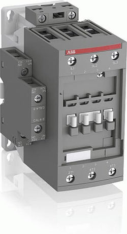
ABB
1SBL281001R8810 ABB - A30-30-10 230-240V 50Hz / 240-260V 60Hz
Sale price
$600.00
Only 1 unit leftA30-30-10 230-240V 50Hz / 240-260V 60Hz Contactor

Ordering
1 piece
85364900
Popular Downloads
Dimensions
45 mm
101 mm
86 mm
0.4 kg
Technical
2
2
0
0
4P
IEC/EN 60947-1, IEC/EN 60947-4-1, UL 60335-2-40 LZGH2 A2L, UL 60947-1, UL 60947-4-1, CSA C22.2 No. 60335-2-40 LZGH2 A2L, CAN/CSA C22.2 No.60947-1, CAN/CSA C22.2 No.60947-4-1
Main Circuit 690 V
Main Circuit 50 / 60 Hz
acc. to IEC 60947-4-1, Open Contactors Θ = 40 °C 55 A
(690 V) 40 °C 55 A
(690 V) 60 °C 45 A
(690 V) 70 °C 37 A
(690 V) 40 °C 55 A
(690 V) 60 °C 45 A
(690 V) 70 °C 37 A
(415 V) 60 °C 21.2 A
(440 V) 60 °C 20 A
(500 V) 60 °C 17.6 A
(690 V) 60 °C 10.5 A
(380 / 400 V) 60 °C 22 A
(220 / 230 / 240 V) 60 °C 23.2 A
(415 V) 60 °C 21.2 A
(440 V) 60 °C 20 A
(500 V) 60 °C 17.6 A
(690 V) 60 °C 10.5 A
(380 / 400 V) 60 °C 22 A
(220 / 230 / 240 V) 60 °C 23.2 A
(400 V) 11 kW
(415 V) 11 kW
(440 V) 11 kW
(500 V) 11 kW
(690 V) 9 kW
(220 / 230 / 240 V) 5.5 kW
(400 V) 11 kW
(415 V) 11 kW
(440 V) 11 kW
(500 V) 11 kW
(690 V) 9 kW
(220 / 230 / 240 V) 5.5 kW
at 40 °C Ambient Temp, in Free Air, from a Cold State 10 s 300 A
at 40 °C Ambient Temp, in Free Air, from a Cold State 15 min 55 A
at 40 °C Ambient Temp, in Free Air, from a Cold State 1 min 150 A
at 40 °C Ambient Temp, in Free Air, from a Cold State 1 s 450 A
at 40 °C Ambient Temp, in Free Air, from a Cold State 30 s 225 A
acc. to IEC 60947-4-1 690 V
acc. to UL/CSA 600 V
acc. to IEC 60947-4-1 690 V
acc. to UL/CSA 600 V
6 kV
(AC-1) 600 cycles per hour
3600 cycles per hour
DC Operation 12 ... 20 V
at Rated Operating Conditions AC-1 per Pole 2.3 W
at Rated Operating Conditions AC-3 per Pole 0.42 W
at Rated Operating Conditions AC-1 per Pole 2.3 W
at Rated Operating Conditions AC-3 per Pole 0.42 W
Between Coil De-energization and NC Contact Closing 13 ... 98 ms
Between Coil De-energization and NO Contact Opening 11 ... 95 ms
Between Coil Energization and NC Contact Opening 38 ... 90 ms
Between Coil Energization and NO Contact Closing 40 ... 95 ms
Between Coil De-energization and NC Contact Closing 13 ... 98 ms
Between Coil De-energization and NO Contact Opening 11 ... 95 ms
Between Coil Energization and NC Contact Opening 38 ... 90 ms
Between Coil Energization and NO Contact Closing 40 ... 95 ms
TH35-15 (35 x 15 mm Mounting Rail) acc. to IEC 60715
TH35-7.5 (35 x 7.5 mm Mounting Rail) acc. to IEC 60715
TH35-15 (35 x 15 mm Mounting Rail) acc. to IEC 60715
TH35-7.5 (35 x 7.5 mm Mounting Rail) acc. to IEC 60715
2 x M4 Screws Placed Diagonally
Flexible with Ferrule 1/2x 1.5 ... 16 mm²
Flexible with Insulated Ferrule 1/2x 1.5 ... 16 mm²
Rigid Solid 1/2x 1.5 ... 4 mm²
Rigid Stranded 1/2x 1.5 ... 16 mm²
Flexible with Ferrule 1/2x 1.5 ... 16 mm²
Flexible with Insulated Ferrule 1/2x 1.5 ... 16 mm²
Rigid Solid 1/2x 1.5 ... 4 mm²
Rigid Stranded 1/2x 1.5 ... 16 mm²
Flexible with Ferrule 1/2x 0.75 ... 2.5 mm²
Flexible with Insulated Ferrule 1x 0.75 ... 2.5 mm²
Flexible with Insulated Ferrule 2x 0.75 ... 1.5 mm²
Rigid Solid 1/2x 1 ... 2.5 mm²
Rigid Stranded 1/2x 1 ... 2.5 mm²
Flexible with Ferrule 1/2x 0.75 ... 2.5 mm²
Flexible with Insulated Ferrule 1x 0.75 ... 2.5 mm²
Flexible with Insulated Ferrule 2x 0.75 ... 1.5 mm²
Rigid Solid 1/2x 1 ... 2.5 mm²
Rigid Stranded 1/2x 1 ... 2.5 mm²
Control Circuit 10 mm
Main Circuit 12 mm
Control Circuit 10 mm
Main Circuit 12 mm
acc. to IEC 60529, IEC 60947-1, EN 60529 Coil Terminals IP20
acc. to IEC 60529, IEC 60947-1, EN 60529 Main Terminals IP20
acc. to IEC 60529, IEC 60947-1, EN 60529 Coil Terminals IP20
acc. to IEC 60529, IEC 60947-1, EN 60529 Main Terminals IP20
Control Circuit 1.2 N·m
Main Circuit 2.5 N·m
Control Circuit 1.2 N·m
Main Circuit 2.5 N·m
Screw Terminals
Block Contactor
Technical UL/CSA
Main Circuit 600 V
(600 V AC) 55 A
Rigid Solid 1/2x 16-10 AWG
Rigid Stranded 1/2x 16-6 AWG
Rigid Solid 1/2x 16-10 AWG
Rigid Stranded 1/2x 16-6 AWG
Rigid Solid 1/2x 18-14 AWG
Rigid Stranded 1/2x 18-14 AWG
Rigid Solid 1/2x 18-14 AWG
Rigid Stranded 1/2x 18-14 AWG
Control Circuit 11 in·lb
Main Circuit 22 in·lb
Control Circuit 11 in·lb
Main Circuit 22 in·lb
Environmental
Close to Contactor for Storage -60 ... +80 °C
Near Contactor for Operation in Free Air -40 ... 70 °C
Close to Contactor for Storage -60 ... +80 °C
Near Contactor for Operation in Free Air -40 ... 70 °C
Category B according to IEC 60947-1 Annex Q
Without Derating 3000 m
Closed, Shock Direction: A 30 g
Closed, Shock Direction: B1 25 g
Closed, Shock Direction: B2 15 g
Closed, Shock Direction: C1 25 g
Closed, Shock Direction: C2 25 g
Open, Shock Direction: A 25 g
Open, Shock Direction: B1 5 g
Open, Shock Direction: B2 10 g
Open, Shock Direction: C1 20 g
Open, Shock Direction: C2 20 g
4g Closed Position & 2g Open position 5 ... 300 Hz
3
Material Compliance
Following EU Directive 2011/65/EU and Amendment 2015/863 July 22, 2019
Business To Business
5. Small Equipment (No External Dimension More Than 50 cm)
ABB EcoSolutions
Recycled Cardboard - 86 %
Recycled Metal - 28 %
Certificates and Declarations
Container Information
box 1 piece
87 mm
103 mm
47 mm
0.4 kg
3471523116900
box 18 piece
250 mm
300 mm
315 mm
14.4 kg
External Classifications and Standards
Q
EC000066 - Power contactor, AC switching
EC000066 - Power contactor, AC switching
EC000066 - Power contactor, AC switching
V11.0 : 27371003
39121529
4758 >> Iec Contactors
3705856
Ordering
1 piece
85364900
Popular Downloads
Dimensions
45 mm
101 mm
86 mm
0.36 kg
Technical
2
2
0
0
4P
IEC/EN 60947-1, IEC/EN 60947-4-1, UL 60335-2-40 LZGH2 A2L, UL 60947-1, UL 60947-4-1, CSA C22.2 No. 60335-2-40 LZGH2 A2L, CAN/CSA C22.2 No.60947-1, CAN/CSA C22.2 No.60947-4-1
Main Circuit 690 V
Control Circuit 50 / 60 Hz
Main Circuit 50 / 60 Hz
Control Circuit 50 / 60 Hz
Main Circuit 50 / 60 Hz
acc. to IEC 60947-4-1, Open Contactors Θ = 40 °C 55 A
(690 V) 40 °C 55 A
(690 V) 60 °C 45 A
(690 V) 70 °C 37 A
(690 V) 40 °C 55 A
(690 V) 60 °C 45 A
(690 V) 70 °C 37 A
(415 V) 60 °C 21.2 A
(440 V) 60 °C 20 A
(500 V) 60 °C 17.6 A
(690 V) 60 °C 10.5 A
(380 / 400 V) 60 °C 22 A
(220 / 230 / 240 V) 60 °C 23.2 A
(415 V) 60 °C 21.2 A
(440 V) 60 °C 20 A
(500 V) 60 °C 17.6 A
(690 V) 60 °C 10.5 A
(380 / 400 V) 60 °C 22 A
(220 / 230 / 240 V) 60 °C 23.2 A
(400 V) 11 kW
(415 V) 11 kW
(440 V) 11 kW
(500 V) 11 kW
(690 V) 9 kW
(220 / 230 / 240 V) 5.5 kW
(400 V) 11 kW
(415 V) 11 kW
(440 V) 11 kW
(500 V) 11 kW
(690 V) 9 kW
(220 / 230 / 240 V) 5.5 kW
at 40 °C Ambient Temp, in Free Air, from a Cold State 10 s 300 A
at 40 °C Ambient Temp, in Free Air, from a Cold State 15 min 55 A
at 40 °C Ambient Temp, in Free Air, from a Cold State 1 min 150 A
at 40 °C Ambient Temp, in Free Air, from a Cold State 1 s 450 A
at 40 °C Ambient Temp, in Free Air, from a Cold State 30 s 225 A
at 40 °C Ambient Temp, in Free Air, from a Cold State 10 s 300 A
at 40 °C Ambient Temp, in Free Air, from a Cold State 15 min 55 A
at 40 °C Ambient Temp, in Free Air, from a Cold State 1 min 150 A
at 40 °C Ambient Temp, in Free Air, from a Cold State 1 s 450 A
at 40 °C Ambient Temp, in Free Air, from a Cold State 30 s 225 A
acc. to IEC 60947-4-1 690 V
acc. to UL/CSA 600 V
acc. to IEC 60947-4-1 690 V
acc. to UL/CSA 600 V
6 kV
(AC-1) 600 cycles per hour
3600 cycles per hour
50 Hz 24 ... 60 V
60 Hz 24 ... 60 V
DC Operation 20 ... 60 V
50 Hz 24 ... 60 V
60 Hz 24 ... 60 V
DC Operation 20 ... 60 V
at Rated Operating Conditions AC-1 per Pole 2.3 W
at Rated Operating Conditions AC-3 per Pole 0.42 W
at Rated Operating Conditions AC-1 per Pole 2.3 W
at Rated Operating Conditions AC-3 per Pole 0.42 W
Between Coil De-energization and NC Contact Closing 13 ... 98 ms
Between Coil De-energization and NO Contact Opening 11 ... 95 ms
Between Coil Energization and NC Contact Opening 38 ... 90 ms
Between Coil Energization and NO Contact Closing 40 ... 95 ms
Between Coil De-energization and NC Contact Closing 13 ... 98 ms
Between Coil De-energization and NO Contact Opening 11 ... 95 ms
Between Coil Energization and NC Contact Opening 38 ... 90 ms
Between Coil Energization and NO Contact Closing 40 ... 95 ms
TH35-15 (35 x 15 mm Mounting Rail) acc. to IEC 60715
TH35-7.5 (35 x 7.5 mm Mounting Rail) acc. to IEC 60715
TH35-15 (35 x 15 mm Mounting Rail) acc. to IEC 60715
TH35-7.5 (35 x 7.5 mm Mounting Rail) acc. to IEC 60715
2 x M4 Screws Placed Diagonally
Flexible with Ferrule 1/2x 1.5 ... 16 mm²
Flexible with Insulated Ferrule 1/2x 1.5 ... 16 mm²
Rigid Solid 1/2x 1.5 ... 4 mm²
Rigid Stranded 1/2x 1.5 ... 16 mm²
Flexible with Ferrule 1/2x 1.5 ... 16 mm²
Flexible with Insulated Ferrule 1/2x 1.5 ... 16 mm²
Rigid Solid 1/2x 1.5 ... 4 mm²
Rigid Stranded 1/2x 1.5 ... 16 mm²
Flexible with Ferrule 1/2x 0.75 ... 2.5 mm²
Flexible with Insulated Ferrule 1x 0.75 ... 2.5 mm²
Flexible with Insulated Ferrule 2x 0.75 ... 1.5 mm²
Rigid Solid 1/2x 1 ... 2.5 mm²
Rigid Stranded 1/2x 1 ... 2.5 mm²
Flexible with Ferrule 1/2x 0.75 ... 2.5 mm²
Flexible with Insulated Ferrule 1x 0.75 ... 2.5 mm²
Flexible with Insulated Ferrule 2x 0.75 ... 1.5 mm²
Rigid Solid 1/2x 1 ... 2.5 mm²
Rigid Stranded 1/2x 1 ... 2.5 mm²
Control Circuit 10 mm
Main Circuit 12 mm
Control Circuit 10 mm
Main Circuit 12 mm
acc. to IEC 60529, IEC 60947-1, EN 60529 Coil Terminals IP20
acc. to IEC 60529, IEC 60947-1, EN 60529 Main Terminals IP20
acc. to IEC 60529, IEC 60947-1, EN 60529 Coil Terminals IP20
acc. to IEC 60529, IEC 60947-1, EN 60529 Main Terminals IP20
Control Circuit 1.2 N·m
Main Circuit 2.5 N·m
Control Circuit 1.2 N·m
Main Circuit 2.5 N·m
Screw Terminals
Block Contactor
Technical UL/CSA
Main Circuit 600 V
(600 V AC) 55 A
Rigid Solid 1/2x 16-10 AWG
Rigid Stranded 1/2x 16-6 AWG
Rigid Solid 1/2x 16-10 AWG
Rigid Stranded 1/2x 16-6 AWG
Rigid Solid 1/2x 18-14 AWG
Rigid Stranded 1/2x 18-14 AWG
Rigid Solid 1/2x 18-14 AWG
Rigid Stranded 1/2x 18-14 AWG
Control Circuit 11 in·lb
Main Circuit 22 in·lb
Control Circuit 11 in·lb
Main Circuit 22 in·lb
Environmental
Close to Contactor for Storage -60 ... +80 °C
Near Contactor for Operation in Free Air -40 ... 70 °C
Close to Contactor for Storage -60 ... +80 °C
Near Contactor for Operation in Free Air -40 ... 70 °C
Category B according to IEC 60947-1 Annex Q
Without Derating 3000 m
Closed, Shock Direction: A 30 g
Closed, Shock Direction: B1 25 g
Closed, Shock Direction: B2 15 g
Closed, Shock Direction: C1 25 g
Closed, Shock Direction: C2 25 g
Open, Shock Direction: A 25 g
Open, Shock Direction: B1 5 g
Open, Shock Direction: B2 10 g
Open, Shock Direction: C1 20 g
Open, Shock Direction: C2 20 g
Closed, Shock Direction: A 30 g
Closed, Shock Direction: B1 25 g
Closed, Shock Direction: B2 15 g
Closed, Shock Direction: C1 25 g
Closed, Shock Direction: C2 25 g
Open, Shock Direction: A 25 g
Open, Shock Direction: B1 5 g
Open, Shock Direction: B2 10 g
Open, Shock Direction: C1 20 g
Open, Shock Direction: C2 20 g
4g Closed Position & 2g Open position 5 ... 300 Hz
3
Material Compliance
Following EU Directive 2011/65/EU and Amendment 2015/863 July 22, 2019
Business To Business
5. Small Equipment (No External Dimension More Than 50 cm)
ABB EcoSolutions
Recycled Cardboard - 86 %
Recycled Metal - 28 %
Certificates and Declarations
Container Information
box 1 piece
87 mm
103 mm
47 mm
0.36 kg
3471523116511
box 18 piece
250 mm
300 mm
315 mm
12.96 kg
External Classifications and Standards
Q
EC000066 - Power contactor, AC switching
EC000066 - Power contactor, AC switching
EC000066 - Power contactor, AC switching
V11.0 : 27371003
39121529
4758 >> Iec Contactors
3705852
3211522

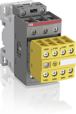
A45-40-00 220-230V 50Hz / 230-240V 60Hz Contactor

A40-30-01 230-240V 50Hz / 240-260V 60Hz Contactor

A40-30-01 220-230V 50Hz / 230-240V 60Hz Contactor
Ordering
1 piece
85364900
Popular Downloads
Dimensions
45 mm
119.5 mm
86 mm
0.36 kg
Technical
3
0
2
2
3P
IEC/EN 60947-1, IEC/EN 60947-4-1, UL 60335-2-40 LZGH2 A2L, UL 60947-4-1, CSA C22.2 No. 60335-2-40 LZGH2 A2L, CSA C22.2 No. 60947-4-1
Auxiliary Circuit 690 V
Main Circuit 690 V
Auxiliary Circuit 690 V
Main Circuit 690 V
Auxiliary Circuit 50 / 60 Hz
Control Circuit 50 / 60 Hz
Main Circuit 50 / 60 Hz
Auxiliary Circuit 50 / 60 Hz
Control Circuit 50 / 60 Hz
Main Circuit 50 / 60 Hz
acc. to IEC 60947-4-1, Open Contactors Θ = 40 °C 50 A
acc. to IEC 60947-5-1, Θ = 40 °C 16 A
acc. to IEC 60947-4-1, Open Contactors Θ = 40 °C 50 A
acc. to IEC 60947-5-1, Θ = 40 °C 16 A
(690 V) 40 °C 50 A
(690 V) 60 °C 42 A
(690 V) 70 °C 37 A
(690 V) 40 °C 50 A
(690 V) 60 °C 42 A
(690 V) 70 °C 37 A
(415 V) 60 °C 38 A
(440 V) 60 °C 38 A
(500 V) 60 °C 33 A
(690 V) 60 °C 24 A
(380 / 400 V) 60 °C 38 A
(220 / 230 / 240 V) 60 °C 40 A
(415 V) 60 °C 38 A
(440 V) 60 °C 38 A
(500 V) 60 °C 33 A
(690 V) 60 °C 24 A
(380 / 400 V) 60 °C 38 A
(220 / 230 / 240 V) 60 °C 40 A
(415 V) 60 °C 38 A
(440 V) 60 °C 38 A
(500 V) 60 °C 33 A
(690 V) 60 °C 24 A
(380 / 400 V) 60 °C 38 A
(220 / 230 / 240 V) 60 °C 40 A
(415 V) 60 °C 38 A
(440 V) 60 °C 38 A
(500 V) 60 °C 33 A
(690 V) 60 °C 24 A
(380 / 400 V) 60 °C 38 A
(220 / 230 / 240 V) 60 °C 40 A
(500 V) 2 A
(690 V) 2 A
(24 / 127 V) 6 A
(220 / 240 V) 4 A
(400 / 440 V) 3 A
(500 V) 2 A
(690 V) 2 A
(24 / 127 V) 6 A
(220 / 240 V) 4 A
(400 / 440 V) 3 A
(110 V) 2 Poles in Series, 40 °C 50 A
(110 V) 2 Poles in Series, 60 °C 42 A
(110 V) 2 Poles in Series, 70 °C 37 A
(110 V) 3 Poles in Series, 40 °C 50 A
(110 V) 3 Poles in Series, 60 °C 42 A
(110 V) 3 Poles in Series, 70 °C 37 A
(220 V) 3 Poles in Series, 40 °C 50 A
(220 V) 3 Poles in Series, 60 °C 42 A
(220 V) 3 Poles in Series, 70 °C 37 A
(72 V) 1-Pole, 40 °C 50 A
(72 V) 1-Pole, 60 °C 42 A
(72 V) 1-Pole, 70 °C 37 A
(72 V) 2 Poles in Series, 40 °C 50 A
(72 V) 2 Poles in Series, 60 °C 42 A
(72 V) 2 Poles in Series, 70 °C 37 A
(72 V) 3 Poles in Series, 40 °C 50 A
(72 V) 3 Poles in Series, 60 °C 42 A
(72 V) 3 Poles in Series, 70 °C 37 A
(110 V) 2 Poles in Series, 40 °C 50 A
(110 V) 2 Poles in Series, 60 °C 42 A
(110 V) 2 Poles in Series, 70 °C 37 A
(110 V) 3 Poles in Series, 40 °C 50 A
(110 V) 3 Poles in Series, 60 °C 42 A
(110 V) 3 Poles in Series, 70 °C 37 A
(220 V) 3 Poles in Series, 40 °C 50 A
(220 V) 3 Poles in Series, 60 °C 42 A
(220 V) 3 Poles in Series, 70 °C 37 A
(72 V) 1-Pole, 40 °C 50 A
(110 V) 2 Poles in Series, 40 °C 50 A
(110 V) 2 Poles in Series, 60 °C 42 A
(110 V) 2 Poles in Series, 70 °C 37 A
(110 V) 3 Poles in Series, 40 °C 50 A
(110 V) 3 Poles in Series, 60 °C 42 A
(110 V) 3 Poles in Series, 70 °C 37 A
(220 V) 3 Poles in Series, 40 °C 50 A
(220 V) 3 Poles in Series, 60 °C 42 A
(220 V) 3 Poles in Series, 70 °C 37 A
(72 V) 1-Pole, 40 °C 50 A
(72 V) 1-Pole, 60 °C 42 A
(72 V) 1-Pole, 70 °C 37 A
(72 V) 2 Poles in Series, 40 °C 50 A
(72 V) 2 Poles in Series, 60 °C 42 A
(72 V) 2 Poles in Series, 70 °C 37 A
(72 V) 3 Poles in Series, 40 °C 50 A
(72 V) 3 Poles in Series, 60 °C 42 A
(72 V) 3 Poles in Series, 70 °C 37 A
(110 V) 2 Poles in Series, 40 °C 50 A
(110 V) 2 Poles in Series, 60 °C 42 A
(110 V) 2 Poles in Series, 70 °C 37 A
(110 V) 3 Poles in Series, 40 °C 50 A
(110 V) 3 Poles in Series, 60 °C 42 A
(110 V) 3 Poles in Series, 70 °C 37 A
(220 V) 3 Poles in Series, 40 °C 50 A
(220 V) 3 Poles in Series, 60 °C 42 A
(220 V) 3 Poles in Series, 70 °C 37 A
(72 V) 1-Pole, 40 °C 50 A
(110 V) 2 Poles in Series, 40 °C 50 A
(110 V) 2 Poles in Series, 60 °C 42 A
(110 V) 2 Poles in Series, 70 °C 37 A
(110 V) 3 Poles in Series, 40 °C 50 A
(110 V) 3 Poles in Series, 60 °C 42 A
(110 V) 3 Poles in Series, 70 °C 37 A
(220 V) 3 Poles in Series, 40 °C 25 A
(220 V) 3 Poles in Series, 60 °C 25 A
(220 V) 3 Poles in Series, 70 °C 25 A
(72 V) 1-Pole, 40 °C 25 A
(72 V) 1-Pole, 60 °C 25 A
(72 V) 1-Pole, 70 °C 25 A
(72 V) 2 Poles in Series, 40 °C 50 A
(72 V) 2 Poles in Series, 60 °C 42 A
(72 V) 2 Poles in Series, 70 °C 37 A
(72 V) 3 Poles in Series, 40 °C 50 A
(72 V) 3 Poles in Series, 60 °C 42 A
(72 V) 3 Poles in Series, 70 °C 37 A
(110 V) 2 Poles in Series, 40 °C 50 A
(110 V) 2 Poles in Series, 60 °C 42 A
(110 V) 2 Poles in Series, 70 °C 37 A
(110 V) 3 Poles in Series, 40 °C 50 A
(110 V) 3 Poles in Series, 60 °C 42 A
(110 V) 3 Poles in Series, 70 °C 37 A
(220 V) 3 Poles in Series, 40 °C 25 A
(220 V) 3 Poles in Series, 60 °C 25 A
(220 V) 3 Poles in Series, 70 °C 25 A
(72 V) 1-Pole, 40 °C 25 A
(24 V) 6 A / 144 W
(48 V) 2.8 A / 134 W
(72 V) 1 A / 72 W
(110 V) 0.55 A / 60 W
(125 V) 0.55 A / 69 W
(220 V) 0.27 A / 60 W
(250 V) 0.27 A / 68 W
(400 V) 0.15 A / 60 W
(500 V) 0.13 A / 65 W
(600 V) 0.1 A / 60 W
(24 V) 6 A / 144 W
(48 V) 2.8 A / 134 W
(72 V) 1 A / 72 W
(110 V) 0.55 A / 60 W
(125 V) 0.55 A / 69 W
(220 V) 0.27 A / 60 W
(250 V) 0.27 A / 68 W
(400 V) 0.15 A / 60 W
(500 V) 0.13 A / 65 W
(600 V) 0.1 A / 60 W
(400 V) 18.5 kW
(415 V) 18.5 kW
(440 V) 22 kW
(500 V) 22 kW
(690 V) 22 kW
(380 / 400 V) 18.5 kW
(220 / 230 / 240 V) 11 kW
(400 V) 18.5 kW
(415 V) 18.5 kW
(440 V) 22 kW
(500 V) 22 kW
(690 V) 22 kW
(380 / 400 V) 18.5 kW
(220 / 230 / 240 V) 11 kW
(415 V) 18.5 kW
(440 V) 22 kW
(500 V) 22 kW
(690 V) 22 kW
(380 / 400 V) 18.5 kW
(220 / 230 / 240 V) 11 kW
(415 V) 18.5 kW
(440 V) 22 kW
(500 V) 22 kW
(690 V) 22 kW
(380 / 400 V) 18.5 kW
(220 / 230 / 240 V) 11 kW
at 40 °C Ambient Temp, in Free Air, from a Cold State 10 s 350 A
at 40 °C Ambient Temp, in Free Air, from a Cold State 15 min 50 A
at 40 °C Ambient Temp, in Free Air, from a Cold State 1 min 150 A
at 40 °C Ambient Temp, in Free Air, from a Cold State 1 s 700 A
at 40 °C Ambient Temp, in Free Air, from a Cold State 30 s 225 A
for 0.1 s 140 A
for 1 s 100 A
at 40 °C Ambient Temp, in Free Air, from a Cold State 10 s 350 A
at 40 °C Ambient Temp, in Free Air, from a Cold State 15 min 50 A
at 40 °C Ambient Temp, in Free Air, from a Cold State 1 min 150 A
at 40 °C Ambient Temp, in Free Air, from a Cold State 1 s 700 A
at 40 °C Ambient Temp, in Free Air, from a Cold State 30 s 225 A
for 0.1 s 140 A
for 1 s 100 A
cos phi=0.45 (cos phi=0.35 for Ie > 100 A) at 440 V 500 A
cos phi=0.45 (cos phi=0.35 for Ie > 100 A) at 690 V 200 A
cos phi=0.45 (cos phi=0.35 for Ie > 100 A) at 440 V 500 A
cos phi=0.45 (cos phi=0.35 for Ie > 100 A) at 690 V 200 A
acc. to IEC 60947-4-1 690 V
acc. to IEC 60947-5-1 690 V
acc. to UL/CSA 600 V
acc. to IEC 60947-4-1 690 V
acc. to IEC 60947-5-1 690 V
acc. to UL/CSA 600 V
6 kV
(AC-1) 600 cycles per hour
(AC-15) 1200 cycles per hour
(AC-2 / AC-4) 150 cycles per hour
(AC-3) 1200 cycles per hour
(DC-13) 900 cycles per hour
(AC-1) 600 cycles per hour
(AC-15) 1200 cycles per hour
(AC-2 / AC-4) 150 cycles per hour
(AC-3) 1200 cycles per hour
(DC-13) 900 cycles per hour
3600 cycles per hour
50 Hz 24 ... 60 V
60 Hz 24 ... 60 V
DC Operation 20 ... 60 V
50 Hz 24 ... 60 V
60 Hz 24 ... 60 V
DC Operation 20 ... 60 V
at 6 A per Pole 0.1 W
at Rated Operating Conditions AC-1 per Pole 2.4 W
at Rated Operating Conditions AC-3 per Pole 1.3 W
at 6 A per Pole 0.1 W
at Rated Operating Conditions AC-1 per Pole 2.4 W
at Rated Operating Conditions AC-3 per Pole 1.3 W
Between Coil De-energization and NC Contact Closing 13 ... 98 ms
Between Coil De-energization and NO Contact Opening 11 ... 95 ms
Between Coil Energization and NC Contact Opening 38 ... 90 ms
Between Coil Energization and NO Contact Closing 40 ... 95 ms
Between Coil De-energization and NC Contact Closing 13 ... 98 ms
Between Coil De-energization and NO Contact Opening 11 ... 95 ms
Between Coil Energization and NC Contact Opening 38 ... 90 ms
Between Coil Energization and NO Contact Closing 40 ... 95 ms
TH35-15 (35 x 15 mm Mounting Rail) acc. to IEC 60715
TH35-7.5 (35 x 7.5 mm Mounting Rail) acc. to IEC 60715
TH35-15 (35 x 15 mm Mounting Rail) acc. to IEC 60715
TH35-7.5 (35 x 7.5 mm Mounting Rail) acc. to IEC 60715
2 x M4 Screws Placed Diagonally
Flexible with Ferrule 1/2x 1.5 ... 10 mm²
Flexible with Insulated Ferrule 1x 1.5 ... 10 mm²
Flexible with Insulated Ferrule 2x 1.5 ... 4 mm²
Rigid Solid 1/2x 2.5 ... 4 mm²
Rigid Stranded 1/2x 2.5 ... 10 mm²
Flexible with Ferrule 1/2x 1.5 ... 10 mm²
Flexible with Insulated Ferrule 1x 1.5 ... 10 mm²
Flexible with Insulated Ferrule 2x 1.5 ... 4 mm²
Rigid Solid 1/2x 2.5 ... 4 mm²
Rigid Stranded 1/2x 2.5 ... 10 mm²
Flexible with Ferrule 1/2x 0.75 ... 2.5 mm²
Flexible with Insulated Ferrule 1x 0.75 ... 2.5 mm²
Flexible with Insulated Ferrule 2x 0.75 ... 1.5 mm²
Rigid Solid 1/2x 1 ... 2.5 mm²
Rigid Stranded 1/2x 1 ... 2.5 mm²
Flexible with Ferrule 1/2x 0.75 ... 2.5 mm²
Flexible with Insulated Ferrule 1x 0.75 ... 2.5 mm²
Flexible with Insulated Ferrule 2x 0.75 ... 1.5 mm²
Rigid Solid 1/2x 1 ... 2.5 mm²
Rigid Stranded 1/2x 1 ... 2.5 mm²
Flexible with Ferrule 1/2x 0.75 ... 2.5 mm²
Flexible with Insulated Ferrule 1x 0.75 ... 2.5 mm²
Flexible with Insulated Ferrule 2x 0.75 ... 1.5 mm²
Rigid Solid 1/2x 1 ... 2.5 mm²
Rigid Stranded 1/2x 1 ... 2.5 mm²
Flexible with Ferrule 1/2x 0.75 ... 2.5 mm²
Flexible with Insulated Ferrule 1x 0.75 ... 2.5 mm²
Flexible with Insulated Ferrule 2x 0.75 ... 1.5 mm²
Rigid Solid 1/2x 1 ... 2.5 mm²
Rigid Stranded 1/2x 1 ... 2.5 mm²
Auxiliary Circuit 10 mm
Control Circuit 10 mm
Main Circuit 14 mm
Auxiliary Circuit 10 mm
Control Circuit 10 mm
Main Circuit 14 mm
acc. to IEC 60529, IEC 60947-1, EN 60529 Auxiliary Terminals IP20
acc. to IEC 60529, IEC 60947-1, EN 60529 Coil Terminals IP20
acc. to IEC 60529, IEC 60947-1, EN 60529 Main Terminals IP20
acc. to IEC 60529, IEC 60947-1, EN 60529 Auxiliary Terminals IP20
acc. to IEC 60529, IEC 60947-1, EN 60529 Coil Terminals IP20
acc. to IEC 60529, IEC 60947-1, EN 60529 Main Terminals IP20
Auxiliary Circuit 1.2 N·m
Control Circuit 1.2 N·m
Main Circuit 2.5 N·m
Auxiliary Circuit 1.2 N·m
Control Circuit 1.2 N·m
Main Circuit 2.5 N·m
Screw Terminals
Block Contactor
Technical UL/CSA
Main Circuit 600 V
(600 V AC) 50 A
(120 V AC) Single Phase 2 hp
(200 ... 208 V AC) Three Phase 10 hp
(220 ... 240 V AC) Three Phase 10 hp
(240 V AC) Single Phase 5 hp
(440 ... 480 V AC) Three Phase 25 hp
(550 ... 600 V AC) Three Phase 30 hp
(120 V AC) Single Phase 2 hp
(200 ... 208 V AC) Three Phase 10 hp
(220 ... 240 V AC) Three Phase 10 hp
(240 V AC) Single Phase 5 hp
(440 ... 480 V AC) Three Phase 25 hp
(550 ... 600 V AC) Three Phase 30 hp
Rigid Solid 1/2x 14-10 AWG
Rigid Stranded 1/2x 14-8 AWG
Rigid Solid 1/2x 14-10 AWG
Rigid Stranded 1/2x 14-8 AWG
Rigid Solid 1/2x 18-14 AWG
Rigid Stranded 1/2x 18-14 AWG
Rigid Solid 1/2x 18-14 AWG
Rigid Stranded 1/2x 18-14 AWG
Rigid Solid 1/2x 18-14 AWG
Rigid Stranded 1/2x 18-14 AWG
Rigid Solid 1/2x 18-14 AWG
Rigid Stranded 1/2x 18-14 AWG
Auxiliary Circuit 11 in·lb
Control Circuit 11 in·lb
Main Circuit 22 in·lb
Auxiliary Circuit 11 in·lb
Control Circuit 11 in·lb
Main Circuit 22 in·lb
(120 V AC) Single Phase 24 A
(200 ... 208 V AC) Three Phase 32.2 A
(220 ... 240 V AC) Three Phase 28 A
(240 V AC) Single Phase 28 A
(440 ... 480 V AC) Three Phase 34 A
(550 ... 600 V AC) Three Phase 32 A
(120 V AC) Single Phase 24 A
(200 ... 208 V AC) Three Phase 32.2 A
(220 ... 240 V AC) Three Phase 28 A
(240 V AC) Single Phase 28 A
(440 ... 480 V AC) Three Phase 34 A
(550 ... 600 V AC) Three Phase 32 A
Environmental
Close to Contactor Fitted with Thermal O/L Relay -25 ... 60 °C
Close to Contactor without Thermal O/L Relay -40 ... 70 °C
Close to Contactor for Storage -60 ... +80 °C
Close to Contactor Fitted with Thermal O/L Relay -25 ... 60 °C
Close to Contactor without Thermal O/L Relay -40 ... 70 °C
Close to Contactor for Storage -60 ... +80 °C
Category B according to IEC 60947-1 Annex Q
Without Derating 3000 m
Closed, Shock Direction: A 30 g
Closed, Shock Direction: B1 25 g
Closed, Shock Direction: B2 15 g
Closed, Shock Direction: C1 25 g
Closed, Shock Direction: C2 25 g
Closed, Shock Direction: A 30 g
Closed, Shock Direction: B1 25 g
Closed, Shock Direction: B2 15 g
Closed, Shock Direction: C1 25 g
Closed, Shock Direction: C2 25 g
4g Closed Position & 2g Open position 5 ... 300 Hz
3
Material Compliance
Business To Business
5. Small Equipment (No External Dimension More Than 50 cm)
ABB EcoSolutions
Recycled Cardboard - 86 %
Recycled Metal - 28 %
Certificates and Declarations
Container Information
box 1 piece
87 mm
121 mm
47 mm
0.36 kg
3471523005495
box 18 piece
250 mm
300 mm
315 mm
12.96 kg
External Classifications and Standards
Q
EC000066 - Power contactor, AC switching
EC000066 - Power contactor, AC switching
EC000066 - Power contactor, AC switching
V11.0 : 27371003
39121529
4758 >> Iec Contactors
3708056
Ordering
1 piece
85364900
Popular Downloads
Dimensions
67 mm
111 mm
125.5 mm
0.99 kg
Technical
3
0
1
1
3P
IEC/EN 60947-1, IEC/EN 60947-4-1, UL 60335-2-40 LZGH2 A2L, UL 60947-1, UL 60947-4-1, CSA C22.2 No. 60335-2-40 LZGH2 A2L, CSA C22.2 No. 60947-1:22, CSA C22.2 No. 60947-4-1:22
Auxiliary Circuit 690 V
Main Circuit 690 V
Auxiliary Circuit 690 V
Main Circuit 690 V
Auxiliary Circuit 50 / 60 Hz
Control Circuit 50 / 60 Hz
Main Circuit 50 / 60 Hz
Auxiliary Circuit 50 / 60 Hz
Control Circuit 50 / 60 Hz
Main Circuit 50 / 60 Hz
acc. to IEC 60947-4-1, Open Contactors Θ = 40 °C 105 A
acc. to IEC 60947-5-1, Θ = 40 °C 16 A
acc. to IEC 60947-4-1, Open Contactors Θ = 40 °C 105 A
acc. to IEC 60947-5-1, Θ = 40 °C 16 A
(690 V) 40 °C 70 A
(690 V) 60 °C 60 A
(690 V) 70 °C 50 A
(690 V) 40 °C 70 A
(690 V) 60 °C 60 A
(690 V) 70 °C 50 A
(415 V) 60 °C 40 A
(440 V) 60 °C 40 A
(500 V) 60 °C 35 A
(690 V) 60 °C 25 A
(380 / 400 V) 60 °C 40 A
(220 / 230 / 240 V) 60 °C 40 A
(415 V) 60 °C 40 A
(440 V) 60 °C 40 A
(500 V) 60 °C 35 A
(690 V) 60 °C 25 A
(380 / 400 V) 60 °C 40 A
(220 / 230 / 240 V) 60 °C 40 A
(415 V) 60 °C 40 A
(440 V) 60 °C 40 A
(500 V) 60 °C 35 A
(690 V) 60 °C 25 A
(380 / 400 V) 60 °C 40 A
(220 / 230 / 240 V) 60 °C 40 A
(415 V) 60 °C 40 A
(440 V) 60 °C 40 A
(500 V) 60 °C 35 A
(690 V) 60 °C 25 A
(380 / 400 V) 60 °C 40 A
(220 / 230 / 240 V) 60 °C 40 A
(500 V) 2 A
(690 V) 2 A
(24 / 127 V) 6 A
(220 / 240 V) 4 A
(400 / 440 V) 3 A
(500 V) 2 A
(690 V) 2 A
(24 / 127 V) 6 A
(220 / 240 V) 4 A
(400 / 440 V) 3 A
(110 V) 2 Poles in Series, 40 °C 70 A
(110 V) 2 Poles in Series, 60 °C 60 A
(110 V) 2 Poles in Series, 70 °C 50 A
(110 V) 3 Poles in Series, 40 °C 70 A
(110 V) 3 Poles in Series, 60 °C 60 A
(110 V) 3 Poles in Series, 70 °C 50 A
(220 V) 3 Poles in Series, 40 °C 70 A
(220 V) 3 Poles in Series, 60 °C 60 A
(220 V) 3 Poles in Series, 70 °C 50 A
(72 V) 1-Pole, 40 °C 70 A
(72 V) 1-Pole, 60 °C 60 A
(72 V) 1-Pole, 70 °C 50 A
(72 V) 2 Poles in Series, 40 °C 70 A
(72 V) 2 Poles in Series, 60 °C 60 A
(72 V) 2 Poles in Series, 70 °C 50 A
(72 V) 3 Poles in Series, 40 °C 70 A
(72 V) 3 Poles in Series, 60 °C 60 A
(72 V) 3 Poles in Series, 70 °C 50 A
(110 V) 2 Poles in Series, 40 °C 70 A
(110 V) 2 Poles in Series, 60 °C 60 A
(110 V) 2 Poles in Series, 70 °C 50 A
(110 V) 3 Poles in Series, 40 °C 70 A
(110 V) 3 Poles in Series, 60 °C 60 A
(110 V) 3 Poles in Series, 70 °C 50 A
(220 V) 3 Poles in Series, 40 °C 70 A
(220 V) 3 Poles in Series, 60 °C 60 A
(220 V) 3 Poles in Series, 70 °C 50 A
(72 V) 1-Pole, 40 °C 70 A
(72 V) 1-Pole, 60 °C 60 A
(72 V) 1-Pole, 70 °C 50 A
(72 V) 2 Poles in Series, 40 °C 70 A
(72 V) 2 Poles in Series, 60 °C 60 A
(72 V) 2 Poles in Series, 70 °C 50 A
(72 V) 3 Poles in Series, 40 °C 70 A
(72 V) 3 Poles in Series, 60 °C 60 A
(72 V) 3 Poles in Series, 70 °C 50 A
(110 V) 2 Poles in Series, 40 °C 70 A
(110 V) 2 Poles in Series, 60 °C 60 A
(110 V) 2 Poles in Series, 70 °C 50 A
(110 V) 3 Poles in Series, 40 °C 70 A
(110 V) 3 Poles in Series, 60 °C 60 A
(110 V) 3 Poles in Series, 70 °C 50 A
(220 V) 3 Poles in Series, 40 °C 70 A
(220 V) 3 Poles in Series, 60 °C 60 A
(220 V) 3 Poles in Series, 70 °C 50 A
(72 V) 1-Pole, 40 °C 70 A
(24 V) 6 A / 144 W
(48 V) 2.8 A / 134 W
(72 V) 1 A / 72 W
(110 V) 0.55 A / 60 W
(125 V) 0.55 A / 69 W
(220 V) 0.27 A / 60 W
(250 V) 0.27 A / 68 W
(400 V) 0.15 A / 60 W
(500 V) 0.13 A / 65 W
(600 V) 0.1 A / 60 W
(24 V) 6 A / 144 W
(48 V) 2.8 A / 134 W
(72 V) 1 A / 72 W
(110 V) 0.55 A / 60 W
(125 V) 0.55 A / 69 W
(220 V) 0.27 A / 60 W
(250 V) 0.27 A / 68 W
(400 V) 0.15 A / 60 W
(500 V) 0.13 A / 65 W
(600 V) 0.1 A / 60 W
(400 V) 18.5 kW
(415 V) 22 kW
(440 V) 22 kW
(500 V) 22 kW
(690 V) 22 kW
(380 / 400 V) 18.5 kW
(220 / 230 / 240 V) 11 kW
(400 V) 18.5 kW
(415 V) 22 kW
(440 V) 22 kW
(500 V) 22 kW
(690 V) 22 kW
(380 / 400 V) 18.5 kW
(220 / 230 / 240 V) 11 kW
(415 V) 22 kW
(440 V) 22 kW
(500 V) 22 kW
(690 V) 22 kW
(380 / 400 V) 18.5 kW
(220 / 230 / 240 V) 11 kW
(415 V) 22 kW
(440 V) 22 kW
(500 V) 22 kW
(690 V) 22 kW
(380 / 400 V) 18.5 kW
(220 / 230 / 240 V) 11 kW
at 40 °C Ambient Temp, in Free Air, from a Cold State 10 s 600 A
at 40 °C Ambient Temp, in Free Air, from a Cold State 15 min 110 A
at 40 °C Ambient Temp, in Free Air, from a Cold State 1 min 250 A
at 40 °C Ambient Temp, in Free Air, from a Cold State 1 s 1000 A
at 40 °C Ambient Temp, in Free Air, from a Cold State 30 s 350 A
for 0.1 s 140 A
for 1 s 100 A
cos phi=0.45 (cos phi=0.35 for Ie > 100 A) at 440 V 950 A
cos phi=0.45 (cos phi=0.35 for Ie > 100 A) at 690 V 600 A
cos phi=0.45 (cos phi=0.35 for Ie > 100 A) at 440 V 950 A
cos phi=0.45 (cos phi=0.35 for Ie > 100 A) at 690 V 600 A
acc. to IEC 60947-4-1 690 V
acc. to IEC 60947-5-1 690 V
acc. to UL/CSA 600 V
acc. to IEC 60947-4-1 690 V
acc. to IEC 60947-5-1 690 V
acc. to UL/CSA 600 V
6 kV
(AC-1) 600 cycles per hour
(AC-15) 1200 cycles per hour
(AC-2 / AC-4) 150 cycles per hour
(AC-3) 1200 cycles per hour
(DC-13) 900 cycles per hour
(AC-1) 600 cycles per hour
(AC-15) 1200 cycles per hour
(AC-2 / AC-4) 150 cycles per hour
(AC-3) 1200 cycles per hour
(DC-13) 900 cycles per hour
3600 cycles per hour
50 Hz 100 ... 250 V
60 Hz 100 ... 250 V
DC Operation 100 ... 250 V
50 Hz 100 ... 250 V
60 Hz 100 ... 250 V
DC Operation 100 ... 250 V
Average Holding Value 50 / 60 Hz 4 V·A
Average Holding Value 50 Hz 4 V·A
Average Holding Value 60 Hz 4 V·A
Average Holding Value DC 2 W
Average Holding Value, from Warm State 2 W
Average Holding Value 50 / 60 Hz 4 V·A
Average Holding Value 50 Hz 4 V·A
Average Holding Value 60 Hz 4 V·A
Average Holding Value DC 2 W
Average Holding Value, from Warm State 2 W
at 6 A per Pole 0.1 W
at Rated Operating Conditions AC-1 per Pole 3 W
at Rated Operating Conditions AC-3 per Pole 1 W
at 6 A per Pole 0.1 W
at Rated Operating Conditions AC-1 per Pole 3 W
at Rated Operating Conditions AC-3 per Pole 1 W
Between Coil De-energization and NC Contact Closing 19 ... 105 ms
Between Coil De-energization and NO Contact Opening 17 ... 100 ms
Between Coil Energization and NC Contact Opening 38 ... 95 ms
Between Coil Energization and NO Contact Closing 42 ... 100 ms
Between Coil De-energization and NC Contact Closing 19 ... 105 ms
Between Coil De-energization and NO Contact Opening 17 ... 100 ms
Between Coil Energization and NC Contact Opening 38 ... 95 ms
Between Coil Energization and NO Contact Closing 42 ... 100 ms
TH35-15 (35 x 15 mm Mounting Rail) acc. to IEC 60715
TH35-7.5 (35 x 7.5 mm Mounting Rail) acc. to IEC 60715
TH35-15 (35 x 15 mm Mounting Rail) acc. to IEC 60715
TH35-7.5 (35 x 7.5 mm Mounting Rail) acc. to IEC 60715
2 x M4 or 2 x M6 Screws Placed Diagonally
Flexible with Ferrule 1/2x 4 ... 35 mm²
Flexible with Insulated Ferrule 1/2x 4 ... 35 mm²
Rigid Stranded 1/2x 6 ... 35 mm²
Flexible with Ferrule 1/2x 4 ... 35 mm²
Flexible with Insulated Ferrule 1/2x 4 ... 35 mm²
Rigid Stranded 1/2x 6 ... 35 mm²
Flexible with Ferrule 1/2x 0.75 ... 2.5 mm²
Flexible with Insulated Ferrule 2x 0.75 ... 1.5 mm²
Flexible with Insulated Ferrule 1x 0.75 ... 2.5 mm²
Rigid 1/2x 1 ... 2.5 mm²
Flexible with Ferrule 1/2x 0.75 ... 2.5 mm²
Flexible with Insulated Ferrule 2x 0.75 ... 1.5 mm²
Flexible with Insulated Ferrule 1x 0.75 ... 2.5 mm²
Rigid 1/2x 1 ... 2.5 mm²
Flexible with Ferrule 1/2x 0.75 ... 2.5 mm²
Flexible with Insulated Ferrule 1x 0.75 ... 2.5 mm²
Flexible with Insulated Ferrule 2x 0.75 ... 1.5 mm²
Rigid Solid 1/2x 1 ... 2.5 mm²
Rigid Stranded 1/2x 1 ... 2.5 mm²
Flexible with Ferrule 1/2x 0.75 ... 2.5 mm²
Flexible with Insulated Ferrule 1x 0.75 ... 2.5 mm²
Flexible with Insulated Ferrule 2x 0.75 ... 1.5 mm²
Rigid Solid 1/2x 1 ... 2.5 mm²
Rigid Stranded 1/2x 1 ... 2.5 mm²
Auxiliary Circuit 10 mm
Control Circuit 10 mm
Main Circuit 16 mm
Auxiliary Circuit 10 mm
Control Circuit 10 mm
Main Circuit 16 mm
acc. to IEC 60529, IEC 60947-1, EN 60529 Auxiliary Terminals IP20
acc. to IEC 60529, IEC 60947-1, EN 60529 Coil Terminals IP20
acc. to IEC 60529, IEC 60947-1, EN 60529 Main Terminals IP10
acc. to IEC 60529, IEC 60947-1, EN 60529 Auxiliary Terminals IP20
acc. to IEC 60529, IEC 60947-1, EN 60529 Coil Terminals IP20
acc. to IEC 60529, IEC 60947-1, EN 60529 Main Terminals IP10
Pozidriv PZ
Auxiliary Circuit 1.2 N·m
Control Circuit 1.2 N·m
Main Circuit 4 N·m
Auxiliary Circuit 1.2 N·m
Control Circuit 1.2 N·m
Main Circuit 4 N·m
Screw Terminals
Block Contactor
Technical UL/CSA
2
45 A
(115 V AC) Single Phase 3 Hp
(200 V AC) Three Phase 10 Hp
(230 V AC) Single Phase 7-1/2 Hp
(230 V AC) Three Phase 15 Hp
(460 V AC) Three Phase 25 Hp
(575 V AC) Three Phase 25 Hp
(115 V AC) Single Phase 3 Hp
(200 V AC) Three Phase 10 Hp
(230 V AC) Single Phase 7-1/2 Hp
(230 V AC) Three Phase 15 Hp
(460 V AC) Three Phase 25 Hp
(575 V AC) Three Phase 25 Hp
Main Circuit 600 V
(600 V AC) 60 A
(120 V AC) Single Phase 3 hp
(200 ... 208 V AC) Three Phase 10 hp
(220 ... 240 V AC) Three Phase 15 hp
(240 V AC) Single Phase 7-1/2 hp
(440 ... 480 V AC) Three Phase 30 hp
(550 ... 600 V AC) Three Phase 40 hp
(120 V AC) Single Phase 3 hp
(200 ... 208 V AC) Three Phase 10 hp
(220 ... 240 V AC) Three Phase 15 hp
(240 V AC) Single Phase 7-1/2 hp
(440 ... 480 V AC) Three Phase 30 hp
(550 ... 600 V AC) Three Phase 40 hp
Rigid Stranded 1/2x 10-2 AWG
Rigid Solid 1/2x 18-14 AWG
Rigid Stranded 1/2x 18-14 AWG
Rigid Solid 1/2x 18-14 AWG
Rigid Stranded 1/2x 18-14 AWG
Auxiliary Circuit 11 in·lb
Control Circuit 11 in·lb
Main Circuit 35 in·lb
Auxiliary Circuit 11 in·lb
Control Circuit 11 in·lb
Main Circuit 35 in·lb
(120 V AC) Single Phase 34 A
(200 ... 208 V AC) Three Phase 32.2 A
(220 ... 240 V AC) Three Phase 42 A
(240 V AC) Single Phase 40 A
(440 ... 480 V AC) Three Phase 41 A
(550 ... 600 V AC) Three Phase 40 A
(120 V AC) Single Phase 34 A
(200 ... 208 V AC) Three Phase 32.2 A
(220 ... 240 V AC) Three Phase 42 A
(240 V AC) Single Phase 40 A
(440 ... 480 V AC) Three Phase 41 A
(550 ... 600 V AC) Three Phase 40 A
Environmental
Close to Contactor Fitted with Thermal O/L Relay -40 ... 70 °C
Close to Contactor without Thermal O/L Relay -40 ... 70 °C
Close to Contactor for Storage -60 ... +80 °C
Close to Contactor Fitted with Thermal O/L Relay -40 ... 70 °C
Close to Contactor without Thermal O/L Relay -40 ... 70 °C
Close to Contactor for Storage -60 ... +80 °C
Category B according to IEC 60947-1 Annex Q
Without Derating 3000 m
Closed, Shock Direction: A 25 g
Closed, Shock Direction: B1 25 g
Closed, Shock Direction: B2 15 g
Closed, Shock Direction: C1 25 g
Closed, Shock Direction: C2 25 g
Open, Shock Direction: B1 5 g
Closed, Shock Direction: A 25 g
Closed, Shock Direction: B1 25 g
Closed, Shock Direction: B2 15 g
Closed, Shock Direction: C1 25 g
Closed, Shock Direction: C2 25 g
Open, Shock Direction: B1 5 g
3g Closed Position & 3g Open Position 5 ... 300 Hz
3
Material Compliance
Following EU Directive 2011/65/EU and Amendment 2015/863 July 22, 2019
bba93f86-cab1-4bdf-98ab-334e20efebe9 France
aab41b3b-f288-46ae-b2a9-06e5f0b4471b Germany
4cb5d32e-29e0-4631-a0a4-af9ef3b0eea0 Hungary
8870b071-fc03-4cf2-95d9-54102176a134 Spain
109b52fa-80da-4dbb-a67d-1e0dbe015481 Belgium
4b433990-61a0-428b-8d4c-7e537c2c769a Hungary
518243f6-bedf-44e1-9109-1cf79ae8ecbb Estonia
527e7616-d3ca-4045-acfa-81dea5cffa55 Greece
c25e8e6c-ba6c-4c5f-a742-75212abf86c8 Portugal
6a54e910-6e1d-48da-b1cd-e0aac9c0b2c7 Bulgaria
03b61e36-715c-40e0-90a8-ec718552d68f Poland
50d16ee4-9f75-44eb-9b03-b4e649f32257 Finland
580aaa2e-4e3b-4357-99c4-d2c79a273474 Germany
6b98ee8b-c69a-41c2-9dc1-5ca099b085ff Norway
e49814bb-2f00-4505-bc1f-cac94c92c89e Belgium
39f7085c-b580-4a36-a322-6deb6bbfee18 Italy
33e3abc9-d491-4037-8812-094130f748bf Poland
a9f4599f-4ce0-40e3-ba3d-67d507cecba9 France
eb0cd70f-e340-44d0-9a25-6a9f16a2202e Sweden
fb1128a1-c3c1-47a7-a1c6-05ed233d9ceb Germany
217ec338-1b73-4044-9791-ab6d2afadb2f Germany
e29fd3d2-c7d3-45e8-886d-590dfc194a4c Denmark
429eb4d1-7c50-486e-965f-a2c15ca0b21e Germany
e8de44f6-c08e-414e-aa2e-23205315eb28 Croatia
f8c26055-6f16-4130-b9a4-013e9ed58758 Czech Republic
8b2fea28-3b77-460b-b679-d0ba79a8bf6d Poland
4bdaa5ea-c540-4347-899e-a74f681b3d8f Netherlands
8cb1740b-9b65-4e96-bd26-79a9684c7a42 Sweden
aab41b3b-f288-46ae-b2a9-06e5f0b4471b Germany
4cb5d32e-29e0-4631-a0a4-af9ef3b0eea0 Hungary
8870b071-fc03-4cf2-95d9-54102176a134 Spain
109b52fa-80da-4dbb-a67d-1e0dbe015481 Belgium
4b433990-61a0-428b-8d4c-7e537c2c769a Hungary
518243f6-bedf-44e1-9109-1cf79ae8ecbb Estonia
527e7616-d3ca-4045-acfa-81dea5cffa55 Greece
c25e8e6c-ba6c-4c5f-a742-75212abf86c8 Portugal
6a54e910-6e1d-48da-b1cd-e0aac9c0b2c7 Bulgaria
03b61e36-715c-40e0-90a8-ec718552d68f Poland
Business To Business
5. Small Equipment (No External Dimension More Than 50 cm)
ABB EcoSolutions
Yes
FSC Recycled Paper - 94.6 %
Recycled Metal - 28.2 %
Certificates and Declarations
Container Information
box 1 piece
150 mm
150 mm
97 mm
1.09 kg
3471523132139
box 10 piece
250 mm
300 mm
300 mm
10.9 kg
External Classifications and Standards
Q
EC000066 - Power contactor, AC switching
EC000066 - Power contactor, AC switching
EC000066 - Power contactor, AC switching
V11.0 : 27371003
39121529
4758 >> Iec Contactors
3707004
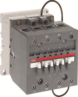
AE45-22-00 24V DC Contactor

Ordering
1 piece
85364900
Popular Downloads
Dimensions
67 mm
111 mm
125.5 mm
1.01 kg
Technical
3
0
1
1
3P
IEC/EN 60947-1, IEC/EN 60947-4-1, UL 60335-2-40 LZGH2 A2L, UL 60947-1, UL 60947-4-1, CSA C22.2 No. 60335-2-40 LZGH2 A2L, CSA C22.2 No. 60947-1:22, CSA C22.2 No. 60947-4-1:22
Auxiliary Circuit 690 V
Main Circuit 690 V
Auxiliary Circuit 690 V
Main Circuit 690 V
Auxiliary Circuit 50 / 60 Hz
Control Circuit 50 / 60 Hz
Main Circuit 50 / 60 Hz
Auxiliary Circuit 50 / 60 Hz
Control Circuit 50 / 60 Hz
Main Circuit 50 / 60 Hz
acc. to IEC 60947-4-1, Open Contactors Θ = 40 °C 105 A
acc. to IEC 60947-5-1, Θ = 40 °C 16 A
acc. to IEC 60947-4-1, Open Contactors Θ = 40 °C 105 A
acc. to IEC 60947-5-1, Θ = 40 °C 16 A
(690 V) 40 °C 70 A
(690 V) 60 °C 60 A
(690 V) 70 °C 50 A
(690 V) 40 °C 70 A
(690 V) 60 °C 60 A
(690 V) 70 °C 50 A
(415 V) 60 °C 40 A
(440 V) 60 °C 40 A
(500 V) 60 °C 35 A
(690 V) 60 °C 25 A
(380 / 400 V) 60 °C 40 A
(220 / 230 / 240 V) 60 °C 40 A
(415 V) 60 °C 40 A
(440 V) 60 °C 40 A
(500 V) 60 °C 35 A
(690 V) 60 °C 25 A
(380 / 400 V) 60 °C 40 A
(220 / 230 / 240 V) 60 °C 40 A
(415 V) 60 °C 40 A
(440 V) 60 °C 40 A
(500 V) 60 °C 35 A
(690 V) 60 °C 25 A
(380 / 400 V) 60 °C 40 A
(220 / 230 / 240 V) 60 °C 40 A
(415 V) 60 °C 40 A
(440 V) 60 °C 40 A
(500 V) 60 °C 35 A
(690 V) 60 °C 25 A
(380 / 400 V) 60 °C 40 A
(220 / 230 / 240 V) 60 °C 40 A
(500 V) 2 A
(690 V) 2 A
(24 / 127 V) 6 A
(220 / 240 V) 4 A
(400 / 440 V) 3 A
(500 V) 2 A
(690 V) 2 A
(24 / 127 V) 6 A
(220 / 240 V) 4 A
(400 / 440 V) 3 A
(110 V) 2 Poles in Series, 40 °C 70 A
(110 V) 2 Poles in Series, 60 °C 60 A
(110 V) 2 Poles in Series, 70 °C 50 A
(110 V) 3 Poles in Series, 40 °C 70 A
(110 V) 3 Poles in Series, 60 °C 60 A
(110 V) 3 Poles in Series, 70 °C 50 A
(220 V) 3 Poles in Series, 40 °C 70 A
(220 V) 3 Poles in Series, 60 °C 60 A
(220 V) 3 Poles in Series, 70 °C 50 A
(72 V) 1-Pole, 40 °C 70 A
(72 V) 1-Pole, 60 °C 60 A
(72 V) 1-Pole, 70 °C 50 A
(72 V) 2 Poles in Series, 40 °C 70 A
(72 V) 2 Poles in Series, 60 °C 60 A
(72 V) 2 Poles in Series, 70 °C 50 A
(72 V) 3 Poles in Series, 40 °C 70 A
(72 V) 3 Poles in Series, 60 °C 60 A
(72 V) 3 Poles in Series, 70 °C 50 A
(110 V) 2 Poles in Series, 40 °C 70 A
(110 V) 2 Poles in Series, 60 °C 60 A
(110 V) 2 Poles in Series, 70 °C 50 A
(110 V) 3 Poles in Series, 40 °C 70 A
(110 V) 3 Poles in Series, 60 °C 60 A
(110 V) 3 Poles in Series, 70 °C 50 A
(220 V) 3 Poles in Series, 40 °C 70 A
(220 V) 3 Poles in Series, 60 °C 60 A
(220 V) 3 Poles in Series, 70 °C 50 A
(72 V) 1-Pole, 40 °C 70 A
(110 V) 2 Poles in Series, 40 °C 70 A
(110 V) 2 Poles in Series, 60 °C 60 A
(110 V) 2 Poles in Series, 70 °C 50 A
(110 V) 3 Poles in Series, 40 °C 70 A
(110 V) 3 Poles in Series, 60 °C 60 A
(110 V) 3 Poles in Series, 70 °C 50 A
(220 V) 3 Poles in Series, 40 °C 70 A
(220 V) 3 Poles in Series, 60 °C 60 A
(220 V) 3 Poles in Series, 70 °C 50 A
(72 V) 1-Pole, 40 °C 70 A
(72 V) 1-Pole, 60 °C 60 A
(72 V) 1-Pole, 70 °C 50 A
(72 V) 2 Poles in Series, 40 °C 70 A
(72 V) 2 Poles in Series, 60 °C 60 A
(72 V) 2 Poles in Series, 70 °C 50 A
(72 V) 3 Poles in Series, 40 °C 70 A
(72 V) 3 Poles in Series, 60 °C 60 A
(72 V) 3 Poles in Series, 70 °C 50 A
(110 V) 2 Poles in Series, 40 °C 70 A
(110 V) 2 Poles in Series, 60 °C 60 A
(110 V) 2 Poles in Series, 70 °C 50 A
(110 V) 3 Poles in Series, 40 °C 70 A
(110 V) 3 Poles in Series, 60 °C 60 A
(110 V) 3 Poles in Series, 70 °C 50 A
(220 V) 3 Poles in Series, 40 °C 70 A
(220 V) 3 Poles in Series, 60 °C 60 A
(220 V) 3 Poles in Series, 70 °C 50 A
(72 V) 1-Pole, 40 °C 70 A
(110 V) 2 Poles in Series, 40 °C 70 A
(110 V) 2 Poles in Series, 60 °C 60 A
(110 V) 2 Poles in Series, 70 °C 50 A
(110 V) 3 Poles in Series, 40 °C 70 A
(110 V) 3 Poles in Series, 60 °C 60 A
(110 V) 3 Poles in Series, 70 °C 50 A
(220 V) 3 Poles in Series, 40 °C 70 A
(220 V) 3 Poles in Series, 60 °C 60 A
(220 V) 3 Poles in Series, 70 °C 50 A
(72 V) 1-Pole, 40 °C 70 A
(72 V) 1-Pole, 60 °C 60 A
(72 V) 1-Pole, 70 °C 50 A
(72 V) 2 Poles in Series, 40 °C 70 A
(72 V) 2 Poles in Series, 60 °C 60 A
(72 V) 2 Poles in Series, 70 °C 50 A
(72 V) 3 Poles in Series, 40 °C 70 A
(72 V) 3 Poles in Series, 60 °C 60 A
(72 V) 3 Poles in Series, 70 °C 50 A
(110 V) 2 Poles in Series, 40 °C 70 A
(110 V) 2 Poles in Series, 60 °C 60 A
(110 V) 2 Poles in Series, 70 °C 50 A
(110 V) 3 Poles in Series, 40 °C 70 A
(110 V) 3 Poles in Series, 60 °C 60 A
(110 V) 3 Poles in Series, 70 °C 50 A
(220 V) 3 Poles in Series, 40 °C 70 A
(220 V) 3 Poles in Series, 60 °C 60 A
(220 V) 3 Poles in Series, 70 °C 50 A
(72 V) 1-Pole, 40 °C 70 A
(24 V) 6 A / 144 W
(48 V) 2.8 A / 134 W
(72 V) 1 A / 72 W
(110 V) 0.55 A / 60 W
(125 V) 0.55 A / 69 W
(220 V) 0.27 A / 60 W
(250 V) 0.27 A / 68 W
(400 V) 0.15 A / 60 W
(500 V) 0.13 A / 65 W
(600 V) 0.1 A / 60 W
(24 V) 6 A / 144 W
(48 V) 2.8 A / 134 W
(72 V) 1 A / 72 W
(110 V) 0.55 A / 60 W
(125 V) 0.55 A / 69 W
(220 V) 0.27 A / 60 W
(250 V) 0.27 A / 68 W
(400 V) 0.15 A / 60 W
(500 V) 0.13 A / 65 W
(600 V) 0.1 A / 60 W
(400 V) 18.5 kW
(415 V) 22 kW
(440 V) 22 kW
(500 V) 22 kW
(690 V) 22 kW
(380 / 400 V) 18.5 kW
(220 / 230 / 240 V) 11 kW
(400 V) 18.5 kW
(415 V) 22 kW
(440 V) 22 kW
(500 V) 22 kW
(690 V) 22 kW
(380 / 400 V) 18.5 kW
(220 / 230 / 240 V) 11 kW
(415 V) 22 kW
(440 V) 22 kW
(500 V) 22 kW
(690 V) 22 kW
(380 / 400 V) 18.5 kW
(220 / 230 / 240 V) 11 kW
(415 V) 22 kW
(440 V) 22 kW
(500 V) 22 kW
(690 V) 22 kW
(380 / 400 V) 18.5 kW
(220 / 230 / 240 V) 11 kW
at 40 °C Ambient Temp, in Free Air, from a Cold State 10 s 600 A
at 40 °C Ambient Temp, in Free Air, from a Cold State 15 min 110 A
at 40 °C Ambient Temp, in Free Air, from a Cold State 1 min 250 A
at 40 °C Ambient Temp, in Free Air, from a Cold State 1 s 1000 A
at 40 °C Ambient Temp, in Free Air, from a Cold State 30 s 350 A
for 0.1 s 140 A
for 1 s 100 A
at 40 °C Ambient Temp, in Free Air, from a Cold State 10 s 600 A
at 40 °C Ambient Temp, in Free Air, from a Cold State 15 min 110 A
at 40 °C Ambient Temp, in Free Air, from a Cold State 1 min 250 A
at 40 °C Ambient Temp, in Free Air, from a Cold State 1 s 1000 A
at 40 °C Ambient Temp, in Free Air, from a Cold State 30 s 350 A
for 0.1 s 140 A
for 1 s 100 A
cos phi=0.45 (cos phi=0.35 for Ie > 100 A) at 440 V 950 A
cos phi=0.45 (cos phi=0.35 for Ie > 100 A) at 690 V 600 A
cos phi=0.45 (cos phi=0.35 for Ie > 100 A) at 440 V 950 A
cos phi=0.45 (cos phi=0.35 for Ie > 100 A) at 690 V 600 A
acc. to IEC 60947-4-1 690 V
acc. to IEC 60947-5-1 690 V
acc. to UL/CSA 600 V
acc. to IEC 60947-4-1 690 V
acc. to IEC 60947-5-1 690 V
acc. to UL/CSA 600 V
6 kV
(AC-1) 600 cycles per hour
(AC-15) 1200 cycles per hour
(AC-2 / AC-4) 150 cycles per hour
(AC-3) 1200 cycles per hour
(DC-13) 900 cycles per hour
(AC-1) 600 cycles per hour
(AC-15) 1200 cycles per hour
(AC-2 / AC-4) 150 cycles per hour
(AC-3) 1200 cycles per hour
(DC-13) 900 cycles per hour
3600 cycles per hour
50 Hz 24 ... 60 V
60 Hz 24 ... 60 V
DC Operation 20 ... 60 V
50 Hz 24 ... 60 V
60 Hz 24 ... 60 V
DC Operation 20 ... 60 V
Average Holding Value 50 / 60 Hz 4 V·A
Average Holding Value 50 Hz 4 V·A
Average Holding Value 60 Hz 4 V·A
Average Holding Value DC 2 W
Average Holding Value, from Warm State 2 W
Average Holding Value 50 / 60 Hz 4 V·A
Average Holding Value 50 Hz 4 V·A
Average Holding Value 60 Hz 4 V·A
Average Holding Value DC 2 W
Average Holding Value, from Warm State 2 W
at 6 A per Pole 0.1 W
at Rated Operating Conditions AC-1 per Pole 3 W
at Rated Operating Conditions AC-3 per Pole 1 W
at 6 A per Pole 0.1 W
at Rated Operating Conditions AC-1 per Pole 3 W
at Rated Operating Conditions AC-3 per Pole 1 W
Between Coil De-energization and NC Contact Closing 19 ... 105 ms
Between Coil De-energization and NO Contact Opening 17 ... 100 ms
Between Coil Energization and NC Contact Opening 38 ... 95 ms
Between Coil Energization and NO Contact Closing 42 ... 100 ms
Between Coil De-energization and NC Contact Closing 19 ... 105 ms
Between Coil De-energization and NO Contact Opening 17 ... 100 ms
Between Coil Energization and NC Contact Opening 38 ... 95 ms
Between Coil Energization and NO Contact Closing 42 ... 100 ms
TH35-15 (35 x 15 mm Mounting Rail) acc. to IEC 60715
TH35-7.5 (35 x 7.5 mm Mounting Rail) acc. to IEC 60715
TH35-15 (35 x 15 mm Mounting Rail) acc. to IEC 60715
TH35-7.5 (35 x 7.5 mm Mounting Rail) acc. to IEC 60715
2 x M4 or 2 x M6 Screws Placed Diagonally
Flexible with Ferrule 1/2x 4 ... 35 mm²
Flexible with Insulated Ferrule 1/2x 4 ... 35 mm²
Rigid Stranded 1/2x 6 ... 35 mm²
Flexible with Ferrule 1/2x 4 ... 35 mm²
Flexible with Insulated Ferrule 1/2x 4 ... 35 mm²
Rigid Stranded 1/2x 6 ... 35 mm²
Flexible with Ferrule 1/2x 0.75 ... 2.5 mm²
Flexible with Insulated Ferrule 2x 0.75 ... 1.5 mm²
Flexible with Insulated Ferrule 1x 0.75 ... 2.5 mm²
Rigid Solid 1/2x 1 ... 2.5 mm²
Rigid Stranded 1/2x 1 ... 2.5 mm²
Flexible with Ferrule 1/2x 0.75 ... 2.5 mm²
Flexible with Insulated Ferrule 2x 0.75 ... 1.5 mm²
Flexible with Insulated Ferrule 1x 0.75 ... 2.5 mm²
Rigid Solid 1/2x 1 ... 2.5 mm²
Rigid Stranded 1/2x 1 ... 2.5 mm²
Flexible with Ferrule 1/2x 0.75 ... 2.5 mm²
Flexible with Insulated Ferrule 1x 0.75 ... 2.5 mm²
Flexible with Insulated Ferrule 2x 0.75 ... 1.5 mm²
Rigid Solid 1/2x 1 ... 2.5 mm²
Rigid Stranded 1/2x 1 ... 2.5 mm²
Flexible with Ferrule 1/2x 0.75 ... 2.5 mm²
Flexible with Insulated Ferrule 1x 0.75 ... 2.5 mm²
Flexible with Insulated Ferrule 2x 0.75 ... 1.5 mm²
Rigid Solid 1/2x 1 ... 2.5 mm²
Rigid Stranded 1/2x 1 ... 2.5 mm²
Auxiliary Circuit 10 mm
Control Circuit 10 mm
Main Circuit 16 mm
Auxiliary Circuit 10 mm
Control Circuit 10 mm
Main Circuit 16 mm
acc. to IEC 60529, IEC 60947-1, EN 60529 Auxiliary Terminals IP20
acc. to IEC 60529, IEC 60947-1, EN 60529 Coil Terminals IP20
acc. to IEC 60529, IEC 60947-1, EN 60529 Main Terminals IP10
acc. to IEC 60529, IEC 60947-1, EN 60529 Auxiliary Terminals IP20
acc. to IEC 60529, IEC 60947-1, EN 60529 Coil Terminals IP20
acc. to IEC 60529, IEC 60947-1, EN 60529 Main Terminals IP10
Pozidriv PZ
Auxiliary Circuit 1.2 N·m
Control Circuit 1.2 N·m
Main Circuit 4 N·m
Auxiliary Circuit 1.2 N·m
Control Circuit 1.2 N·m
Main Circuit 4 N·m
Screw Terminals
Block Contactor
Technical UL/CSA
2
45 A
(115 V AC) Single Phase 3 Hp
(200 V AC) Three Phase 10 Hp
(230 V AC) Single Phase 7-1/2 Hp
(230 V AC) Three Phase 15 Hp
(460 V AC) Three Phase 25 Hp
(575 V AC) Three Phase 25 Hp
(115 V AC) Single Phase 3 Hp
(200 V AC) Three Phase 10 Hp
(230 V AC) Single Phase 7-1/2 Hp
(230 V AC) Three Phase 15 Hp
(460 V AC) Three Phase 25 Hp
(575 V AC) Three Phase 25 Hp
Main Circuit 600 V
(600 V AC) 60 A
(120 V AC) Single Phase 3 hp
(200 ... 208 V AC) Three Phase 10 hp
(220 ... 240 V AC) Three Phase 15 hp
(240 V AC) Single Phase 7-1/2 hp
(440 ... 480 V AC) Three Phase 30 hp
(550 ... 600 V AC) Three Phase 40 hp
(120 V AC) Single Phase 3 hp
(200 ... 208 V AC) Three Phase 10 hp
(220 ... 240 V AC) Three Phase 15 hp
(240 V AC) Single Phase 7-1/2 hp
(440 ... 480 V AC) Three Phase 30 hp
(550 ... 600 V AC) Three Phase 40 hp
Rigid Stranded 1/2x 10-2 AWG
Rigid Solid 1/2x 18-14 AWG
Rigid Stranded 1/2x 18-14 AWG
Rigid Solid 1/2x 18-14 AWG
Rigid Stranded 1/2x 18-14 AWG
Rigid Solid 1/2x 18-14 AWG
Rigid Stranded 1/2x 18-14 AWG
Rigid Solid 1/2x 18-14 AWG
Rigid Stranded 1/2x 18-14 AWG
Auxiliary Circuit 11 in·lb
Control Circuit 11 in·lb
Main Circuit 35 in·lb
Auxiliary Circuit 11 in·lb
Control Circuit 11 in·lb
Main Circuit 35 in·lb
(120 V AC) Single Phase 34 A
(200 ... 208 V AC) Three Phase 32.2 A
(220 ... 240 V AC) Three Phase 42 A
(240 V AC) Single Phase 40 A
(440 ... 480 V AC) Three Phase 41 A
(550 ... 600 V AC) Three Phase 40 A
(120 V AC) Single Phase 34 A
(200 ... 208 V AC) Three Phase 32.2 A
(220 ... 240 V AC) Three Phase 42 A
(240 V AC) Single Phase 40 A
(440 ... 480 V AC) Three Phase 41 A
(550 ... 600 V AC) Three Phase 40 A
Environmental
Close to Contactor Fitted with Thermal O/L Relay -40 ... 70 °C
Close to Contactor without Thermal O/L Relay -40 ... 70 °C
Close to Contactor for Storage -60 ... +80 °C
Close to Contactor Fitted with Thermal O/L Relay -40 ... 70 °C
Close to Contactor without Thermal O/L Relay -40 ... 70 °C
Close to Contactor for Storage -60 ... +80 °C
Category B according to IEC 60947-1 Annex Q
Without Derating 3000 m
Closed, Shock Direction: A 25 g
Closed, Shock Direction: B1 25 g
Closed, Shock Direction: B2 15 g
Closed, Shock Direction: C1 25 g
Closed, Shock Direction: C2 25 g
Open, Shock Direction: B1 5 g
Closed, Shock Direction: A 25 g
Closed, Shock Direction: B1 25 g
Closed, Shock Direction: B2 15 g
Closed, Shock Direction: C1 25 g
Closed, Shock Direction: C2 25 g
Open, Shock Direction: B1 5 g
3g Closed Position & 3g Open Position 5 ... 300 Hz
3
Material Compliance
Following EU Directive 2011/65/EU and Amendment 2015/863 July 22, 2019
Business To Business
5. Small Equipment (No External Dimension More Than 50 cm)
ABB EcoSolutions
Yes
FSC Recycled Paper - 94.6 %
Recycled Metal - 28.2 %
Certificates and Declarations
Container Information
box 1 piece
150 mm
150 mm
97 mm
1.11 kg
3471523132115
box 10 piece
250 mm
300 mm
300 mm
11.1 kg
External Classifications and Standards
Q
EC000066 - Power contactor, AC switching
EC000066 - Power contactor, AC switching
EC000066 - Power contactor, AC switching
V11.0 : 27371003
39121529
4758 >> Iec Contactors
3707002
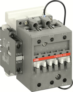
TAE50-30-11 77-143V DC Contactor
A45-40-00 230-240V 50Hz / 240-260V 60Hz Contactor
Main category name:Drives - Motors - Circuits Protection Sub category name:Drives - Motors - Circuits Protection Vendor:ABB