
 1 year warranty


The M340 processor module has a maximum of 1024 discrete and 256 analog I/O (Modbus or Ethernet). 36 application specific channels, product or component type. The processor module can do monitoring, diagnostic counters Modbus, event counters Modbus, is transparent ready, has 4 CANopen racks and 11 slots. It also has 1024 I/O multirack configuration, 704 I/O single rack configuration, analog I/O processor capacity, 256 I/O multirack configuration and 66 I/O single rack configuration. The Modicon M340 offers in a small form factor flexibility and integrated functions. In the heart of your process, it provides plug-and-play solutions with both Schneider Electric and third party devices. The large capacity of Unity Pro SoCollaborative software will ease and shorten programming and commissioning time. Modicon M340 Programmable Automation Controllers (PACs) are built to suit the needs of the process industry and a wide range of demanding automation applications. Modicon M340 PACs can be used individually, but are also the perfect companion to the Modicon M580. Together they can increase the performance, quality, and the profitability of your machine production. M340 PACs have an all in one CPU. It operates at 7 Kinst/ms. By using a multitasking system, it has reflex time. This PAC is programmed with Unity⢠Pro software. The M340 has a USB port for programming and HMI. Two additional Ethernet, CANopen® or Modbus⢠ports are available as required. The memory can process programming code up to 70 Kinst. Application back up is in a supplied memory card. Additional file storage is available up to 128 MB with FTP access. Additional file storage is available up to 128 MB with FTP access. The M340 range doesnât require a battery. It has extended temperature (-25°C +70°C) and conformal coating for operation in harsh environments. Protection for SI and OEM know how by using a SD card technology. Replace or hot swap I/O modules without stopping process. Configuration change on the fly (CCOTF) is used. No need to stop the process to expand system. FTD/DTM configuration tools for plug and play device integration. This simplifies configuration, commissioning, and maintenance. The M340 range is used in process industries, renewable energy applications (Solar, Wind power, etc.), water and cement applications, in manufacturing, in infrastructures and on machines.
Main
| Characteristic | Value(s) |
|---|---|
| Range of Product | Modicon X80 |
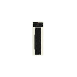
| Accessory / Separate Part Type | Removable connection block |
| Number of terminals | 20 removable screw clamp terminal block |
| Accessory / separate part destination | For module with 20-pin removable terminal block |
Complementary
| Characteristic | Value(s) |
|---|---|
| Product Weight | 0.165 lb(US) (0.075 kg) |

This power module is part of the Modicon X80 modules. This module provides the power supply for each Modicon X80 I/O rack and the modules installed. It is supplied with 24V to 48V DC isolated. It has a case which provides IP 20 protection of the electronics.
Main
| Characteristic | Value(s) |
|---|---|
| Range of Product | Modicon X80 |
| Product or Component Type | Power supply module |
| backplane compatibility | Not compatible with BMEXBP..02 |
| Primary Voltage | 24...48 V isolated |
| Supply circuit type | DC |
| Secondary power | 15 W 3.3 V DC I/O module logic power supply 31.2 W 24 V DC I/O module power supply and processor |
Complementary
| Characteristic | Value(s) |
|---|---|
| Primary voltage limit | 18...62.4 V |
| Input current | 0.83 A 48 V 1.65 A 24 V |
| Inrush current | 30 A 24 V 60 A 48 V |
| I²t on activation | 1 A².s 24 V 3 A².s 48 V |
| It on activation | 0.2 A.s 24 V 0.3 A.s 48 V |
| MTBF reliability | 4600000 H |
| Protection type | Internal fuse not accessible primary circuit Overload protection secondary circuit, 24 V sensor power supply Overvoltage protection secondary circuit, 24 V sensor power supply Short-circuit protection secondary circuit, 24 V sensor power supply |
| Current at secondary voltage | 1.3 A 24 V DC I/O module power supply and processor 4.5 A 3.3 V DC I/O module logic power supply |
| Maximum power dissipation in W | 8.5 W |
| Status LED | 1 LED (Green) rack voltage OK |
| Control Type | RESET push-button cold restart |
| Electrical connection | 1 connector 2 alarm relay 1 connector 5 line supply, protective earth |
| Maximum cable distance between devices | 32.8 ft (10 m) power supply cable copper 0.002 in² (1.5 mm²) 49.2 ft (15 m) power supply cable copper 0.004 in² (2.5 mm²) |
| Insulation resistance | >= 10 MOhm primary/ground >= 10 MOhm primary/secondary |
| Product Weight | 0.75 lb(US) (0.34 kg) |

Discrete output module M238 - 16 outputs relay- 1 removable screw terminal block

Advanced hand-held panel - 640 x 480 pixels VGA - 5.7" - TFT LCD - 24 V DC

Power distribution module - for I/O module 24 V DC & bus

Analog input module, Modicon TM3, 4 inputs (screw) 24 VDC
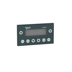
XBTN400 Small 5 V DC Panel w Green Matrix Touch Screen & Keypad

Analog input module, Modicon TM5, 4I, +/-10 V/0...20 mA, 16 bits

HMISTU655 Small 24 V DC Panel w 3.4 Color Touch Screen
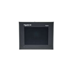
advanced touchscreen panel 320 x 240 pixels QVGA- 5.7" TFT - 96 MB
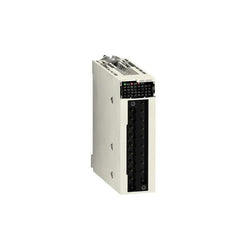
This product is part of the Modicon X80 range, a common platform of modules for Modicon M580 and M340 Programmable Automation Controllers (PAC). This discrete input module has 16 capacitive inputs. It is an input module with an input voltage of 100V AC to 120V AC, a current consumption of 90mA at 3.3V DC and a power dissipation of 3.8W. There is an isolation between channels. This product is robust, high quality and based on the latest innovative technology. It has an external fuse per group of channel 0.5A fast blow protection type. It offers 1504958 hours of MTBF. It is an IP20 rated product. It weighs 0.115kg. It is suitable for medium to large process applications. This product is certified by EAC, RCM, UL, CSA, Merchant Navy, CE. It meets IEC 61131-2, CSA C22.2 No 142, CSA C22.2 No 213 and UL 508 standards. This input module is compatible with 2-wire/3-wire proximity sensors conforming to IEC 60947-5-2. Modicon X80 consists in a compatible modules common platform that reduce maintenance and training costs with same spare parts in stock, and unique training for different Programmable Automation Controllers (PAC).
Main
| Characteristic | Value(s) |
|---|---|
| Range of Product | Modicon X80 |
| Product or Component Type | Discrete input module |
| Discrete input number | 16 |
| Discrete input type | Isolated |
| Input type | Capacitive |
| Discrete input voltage | 100...120 V AC |
| Discrete input current | 5 mA |
Complementary
| Characteristic | Value(s) |
|---|---|
| Input compatibility | 2-wire proximity sensor IEC 60947-5-2 2-wire proximity sensor IEC 61131-2 type 3 |
| Network Frequency | 50/60 Hz |
| Network frequency limits | 47â¦63 Hz |
| Sensor power supply | 85...132 V |
| Current state 1 guaranteed | >= 2.5 mA |
| Current state 0 guaranteed | <= 1 mA |
| Input impedance | 13000 Ohm |
| Insulation resistance | > 10 MOhm 500 V DC |
| Power dissipation in W | 3.8 W |
| AC activation response time | 10 ms |
| AC deactivation response time | 20 ms |
| Typical current consumption | 76 mA 3.3 V DC |
| MTBF reliability | 1120000 H |
| Protection type | 1 external fuse per group of channel 0.5 A fast blow |
| Voltage detection threshold | < 40 V AC sensor fault > 82 V AC sensor OK |
| Status LED | 1 LED (Green) module operating (RUN) 1 LED per channel (Green) channel diagnostic 1 LED (Red) module error (ERR) 1 LED (Red) module I/O |
| Product Weight | 0.254 lb(US) (0.115 kg) |
Non-isolated analog input module X80 - 8 inputs - fast speed

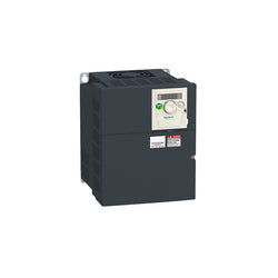
Variable Speed Drive - 11kW- 400V - 3 Phases - Altivar ATV340 Ethernet

This Altivar 320 variable speed drive can feed 3-phase synchronous and asynchronous motors. Its book form factor allows for a simple and compact installation in your automation cabinets. It works at a rated power up to 5.5kW / 7.5hp and a rated voltage from 380V to 500V AC. Its robust design with IEC 60721-3-3 class 3C3 coated printed circuit boards allows to extend machine availability in harsh environmental conditions, for example at ambient temperatures of up to 60°C without the need of additional cooling. It incorporates functions suitable for the most common applications, including torque and speed accuracy at very low speed, high dynamic performance with flux vector control without sensor and extended frequency range for high-speed motors. It also incorporates parallel connection of motors and special drives using the voltage/frequency ratio and static speed accuracy and energy saving for open-loop synchronous motors. The drive software includes 5 safety functions that help machines meet safety requirements, whether or not they are used in conjunction with a Preventa safety module. These safety functions are configured using SoMove software. Altivar Machine ATV320 was designed for Original Equipment Manufacturers (OEMs) that meets simple and advanced application requirements covered for packaging, material handling, textile, material working, mechanical actuators and hoisting. It conforms to international standards IEC/EN 61800-5-1 and IEC/EN 61800-3 (immunity and conducted and radiated EMC emissions). It is also CE, UL, CSA, NOM, EAC and RCM certified. Mounting accessories and external options (braking resistors, line chokes, motor chokes, additional EMC filters) are available with Altivar Machine ATV320 drives. The type of external accessories and options depends on the drive rating. It is designed to be mounted in vertical position (+/- 10 °) on a panel, thanks to 4 fixing holes. It is fully integrated inside Schneider Electricâs EcoStruxure Machine through DTM. It is possible to configure, control, and diagnose ATV320 drives directly in SoMachine and SoMove software by means of the same software brick (DTM).
Main
| Characteristic | Value(s) |
|---|---|
| Range of Product | Altivar Machine ATV320 |
| Product or Component Type | Variable speed drive |
| Product Specific Application | Complex machines |
| Variant | Standard version |
| Format of the drive | Book |
| Mounting Mode | Wall mount |
| Communication Port Protocol | Modbus serial CANopen |
| Option card | communication module, CANopen communication module, EtherCAT communication module, Profibus DP V1 communication module, PROFINET communication module, Ethernet Powerlink communication module, EtherNet/IP communication module, DeviceNet |
| [Us] rated supply voltage | 380...500 V - 15...10 % |
| nominal output current | 14.3 A |
| Motor power kW | 5.5 kW heavy duty |
| EMC filter | Class C2 EMC filter integrated |
| IP degree of protection | IP20 |
Complementary
| Characteristic | Value(s) |
|---|---|
| Discrete input number | 7 |
| Discrete input type | STO safe torque off, 24 V DC1.5 kOhm DI1...DI6 logic inputs, 24 V DC 30 V) DI5 programmable as pulse input 0â¦30 kHz, 24 V DC 30 V) |
| Discrete input logic | Positive logic (source) Negative logic (sink) |
| Discrete output number | 3 |
| Discrete output type | Open collector DQ+ 0â¦1 kHz 30 V DC 100 mA Open collector DQ- 0â¦1 kHz 30 V DC 100 mA |
| Analogue input number | 3 |
| Analogue input type | AI1 voltage 0...10 V DC 30 kOhm 10 bits AI2 bipolar differential voltage +/- 10 V DC 30 kOhm 10 bits AI3 current 0...20 mA (or 4-20 mA, x-20 mA, 20-x mA or other patterns by configuration) 250 Ohm 10 bits |
| Analogue output number | 1 |
| Analogue output type | Software-configurable current AQ1 0...20 mA 800 Ohm 10 bits Software-configurable voltage AQ1 0...10 V DC 470 Ohm 10 bits |
| Relay output type | Configurable relay logic R1A 1 NO 100000 cycles Configurable relay logic R1B 1 NC 100000 cycles Configurable relay logic R1C Configurable relay logic R2A 1 NO 100000 cycles Configurable relay logic R2C |
| Maximum switching current | Relay output R1A, R1B, R1C resistive, cos phi = 1 3 A 250 V AC Relay output R1A, R1B, R1C resistive, cos phi = 1 3 A 30 V DC Relay output R1A, R1B, R1C, R2A, R2C inductive, cos phi = 0.4 7 ms 2 A 250 V AC Relay output R1A, R1B, R1C, R2A, R2C inductive, cos phi = 0.4 7 ms 2 A 30 V DC Relay output R2A, R2C resistive, cos phi = 1 5 A 250 V AC Relay output R2A, R2C resistive, cos phi = 1 5 A 30 V DC |
| Minimum switching current | Relay output R1A, R1B, R1C, R2A, R2C 5 mA 24 V DC |
| Method of access | Slave CANopen |
| 4 quadrant operation possible | True |
| Asynchronous motor control profile | Voltage/frequency ratio, 5 points Flux vector control without sensor, standard Voltage/frequency ratio - Energy Saving, quadratic U/f Flux vector control without sensor - Energy Saving Voltage/frequency ratio, 2 points |
| Synchronous motor control profile | Vector control without sensor |
| Maximum output frequency | 0.599 kHz |
| Acceleration and deceleration ramps | Linear U S CUS Ramp switching Acceleration/deceleration ramp adaptation Acceleration/deceleration automatic stop with DC injection |
| Motor slip compensation | Automatic whatever the load Adjustable 0...300 % Not available in voltage/frequency ratio (2 or 5 points) |
| Switching frequency | 2...16 kHz adjustable 4...16 kHz with derating factor |
| Nominal switching frequency | 4 kHz |
| Braking to standstill | By DC injection |
| Brake chopper integrated | True |
| Line current | 20.7 A 380 V heavy duty) 14.5 A 500 V heavy duty) |
| Maximum Input Current per Phase | 20.7 A |
| Maximum output voltage | 500 V |
| Apparent power | 12.6 kVA 500 V heavy duty) |
| Network Frequency | 50-60 Hz |
| Relative symmetric network frequency tolerance | 5 % |
| Prospective line Isc | 22 kA |
| Base load current at high overload | 14.3 A |
| Power dissipation in W | Fan 195.0 W 380 V 4 kHz |
| With safety function Safely Limited Speed (SLS) | True |
| With safety function Safe brake management (SBC/SBT) | False |
| With safety function Safe Operating Stop (SOS) | False |
| With safety function Safe Position (SP) | False |
| With safety function Safe programmable logic | False |
| With safety function Safe Speed Monitor (SSM) | False |
| With safety function Safe Stop 1 (SS1) | True |
| With sft fct Safe Stop 2 (SS2) | False |
| With safety function Safe torque off (STO) | True |
| With safety function Safely Limited Position (SLP) | False |
| With safety function Safe Direction (SDI) | False |
| Protection type | Input phase breaks drive Overcurrent between output phases and earth drive Overheating protection drive Short-circuit between motor phases drive Thermal protection drive |
| Width | 5.9 in (150 mm) |
| Height | 12.1 in (308.0 mm) |
| Depth | 9.1 in (232.0 mm) |
| Product Weight | 9.7 lb(US) (4.4 kg) |
| Transient overtorque | 170â¦200 % of nominal motor torque |

This Altivar 320 variable speed drive can feed 3-phase synchronous and asynchronous motors. Its book form factor allows for a simple and compact installation in your automation cabinets. It works at a rated power up to 1.5kW / 2hp and a rated voltage from 380V to 500V AC. Its robust design with IEC 60721-3-3 class 3C3 coated printed circuit boards allows to extend machine availability in harsh environmental conditions, for example at ambient temperatures of up to 60°C without the need of additional cooling. It incorporates functions suitable for the most common applications, including torque and speed accuracy at very low speed, high dynamic performance with flux vector control without sensor and extended frequency range for high-speed motors. It also incorporates parallel connection of motors and special drives using the voltage/frequency ratio and static speed accuracy and energy saving for open-loop synchronous motors. The drive software includes 5 safety functions that help machines meet safety requirements, whether or not they are used in conjunction with a Preventa safety module. These safety functions are configured using SoMove software. Altivar Machine ATV320 was designed for Original Equipment Manufacturers (OEMs) that meets simple and advanced application requirements covered for packaging, material handling, textile, material working, mechanical actuators and hoisting. It conforms to international standards IEC/EN 61800-5-1 and IEC/EN 61800-3 (immunity and conducted and radiated EMC emissions). It is also CE, UL, CSA, NOM, EAC and RCM certified. Mounting accessories and external options (braking resistors, line chokes, motor chokes, additional EMC filters) are available with Altivar Machine ATV320 drives. The type of external accessories and options depends on the drive rating. It is designed to be mounted in vertical position (+/- 10 °) on a panel, thanks to 4 fixing holes. It is fully integrated inside Schneider Electricâs EcoStruxure Machine through DTM. It is possible to configure, control, and diagnose ATV320 drives directly in SoMachine and SoMove software by means of the same software brick (DTM).
Main
| Characteristic | Value(s) |
|---|---|
| Range of Product | Altivar Machine ATV320 |
| Product or Component Type | Variable speed drive |
| Product Specific Application | Complex machines |
| Variant | Standard version |
| Format of the drive | Book |
| Mounting Mode | Cabinet mount |
| Communication Port Protocol | Modbus serial CANopen |
| Option card | communication module, CANopen communication module, EtherCAT communication module, Profibus DP V1 communication module, PROFINET communication module, Ethernet Powerlink communication module, EtherNet/IP communication module, DeviceNet |
| [Us] rated supply voltage | 380...500 V - 15...10 % |
| nominal output current | 4.1 A |
| Motor power kW | 1.5 kW heavy duty |
| EMC filter | Class C2 EMC filter integrated |
| IP degree of protection | IP20 |
Complementary
| Characteristic | Value(s) |
|---|---|
| Discrete input number | 7 |
| Discrete input type | STO safe torque off, 24 V DC1.5 kOhm DI1...DI6 logic inputs, 24 V DC 30 V) DI5 programmable as pulse input 0â¦30 kHz, 24 V DC 30 V) |
| Discrete input logic | Positive logic (source) Negative logic (sink) |
| Discrete output number | 3 |
| Discrete output type | Open collector DQ+ 0â¦1 kHz 30 V DC 100 mA Open collector DQ- 0â¦1 kHz 30 V DC 100 mA |
| Analogue input number | 3 |
| Analogue input type | AI1 voltage 0...10 V DC 30 kOhm 10 bits AI2 bipolar differential voltage +/- 10 V DC 30 kOhm 10 bits AI3 current 0...20 mA (or 4-20 mA, x-20 mA, 20-x mA or other patterns by configuration) 250 Ohm 10 bits |
| Analogue output number | 1 |
| Analogue output type | Software-configurable current AQ1 0...20 mA 800 Ohm 10 bits Software-configurable voltage AQ1 0...10 V DC 470 Ohm 10 bits |
| Relay output type | Configurable relay logic R1A 1 NO 100000 cycles Configurable relay logic R1B 1 NC 100000 cycles Configurable relay logic R1C Configurable relay logic R2A 1 NO 100000 cycles Configurable relay logic R2C |
| Maximum switching current | Relay output R1A, R1B, R1C resistive, cos phi = 1 3 A 250 V AC Relay output R1A, R1B, R1C resistive, cos phi = 1 3 A 30 V DC Relay output R1A, R1B, R1C, R2A, R2C inductive, cos phi = 0.4 7 ms 2 A 250 V AC Relay output R1A, R1B, R1C, R2A, R2C inductive, cos phi = 0.4 7 ms 2 A 30 V DC Relay output R2A, R2C resistive, cos phi = 1 5 A 250 V AC Relay output R2A, R2C resistive, cos phi = 1 5 A 30 V DC |
| Minimum switching current | Relay output R1A, R1B, R1C, R2A, R2C 5 mA 24 V DC |
| Method of access | Slave CANopen |
| 4 quadrant operation possible | True |
| Asynchronous motor control profile | Voltage/frequency ratio, 5 points Flux vector control without sensor, standard Voltage/frequency ratio - Energy Saving, quadratic U/f Flux vector control without sensor - Energy Saving Voltage/frequency ratio, 2 points |
| Synchronous motor control profile | Vector control without sensor |
| Maximum output frequency | 0.599 kHz |
| Acceleration and deceleration ramps | Linear U S CUS Ramp switching Acceleration/deceleration ramp adaptation Acceleration/deceleration automatic stop with DC injection |
| Motor slip compensation | Automatic whatever the load Adjustable 0...300 % Not available in voltage/frequency ratio (2 or 5 points) |
| Switching frequency | 2...16 kHz adjustable 4...16 kHz with derating factor |
| Nominal switching frequency | 4 kHz |
| Braking to standstill | By DC injection |
| Brake chopper integrated | True |
| Line current | 6.5 A 380 V heavy duty) 4.9 A 500 V heavy duty) |
| Maximum Input Current per Phase | 6.5 A |
| Maximum output voltage | 500 V |
| Apparent power | 4.2 kVA 500 V heavy duty) |
| Network Frequency | 50-60 Hz |
| Relative symmetric network frequency tolerance | 5 % |
| Prospective line Isc | 5 kA |
| Base load current at high overload | 1.5 A |
| Power dissipation in W | Fan 56.0 W 380 V 4 kHz |
| With safety function Safely Limited Speed (SLS) | True |
| With safety function Safe brake management (SBC/SBT) | False |
| With safety function Safe Operating Stop (SOS) | False |
| With safety function Safe Position (SP) | False |
| With safety function Safe programmable logic | False |
| With safety function Safe Speed Monitor (SSM) | False |
| With safety function Safe Stop 1 (SS1) | True |
| With sft fct Safe Stop 2 (SS2) | False |
| With safety function Safe torque off (STO) | True |
| With safety function Safely Limited Position (SLP) | False |
| With safety function Safe Direction (SDI) | False |
| Protection type | Input phase breaks drive Overcurrent between output phases and earth drive Overheating protection drive Short-circuit between motor phases drive Thermal protection drive |
| Width | 1.8 in (45.0 mm) |
| Height | 12.8 in (325.0 mm) |
| Depth | 9.6 in (245.0 mm) |
| Product Weight | 5.5 lb(US) (2.5 kg) |
| Transient overtorque | 170â¦200 % of nominal motor torque |
Variable Speed Drive Altivar ATV312 - 7.5kW - 18kVA - 269W - 380..500 V - 3-Phase Supply

Variable Speed Drive Altivar ATV312 - 1.5kW - 4.2kVA - 61W - 380..500 V - 3-Phase Supply

This Altivar 312 3-phase variable speed drive has a rated power of 1.1kW, 3.2kVA, and a 380V to 500V AC rated output voltage. It is suitable for industrial machines such as materials handling and packaging, packing, textile machines, special machines, pumps and fans. It has a compact form-factor with 107mmwidth, allowing for a flexible and easy installation on a mounting plate. It also offers a snap-lock seal, status and faults display, a jog dial navigation button and an integrated EMC filter. It offers high readability of key parameters thanks to a bright LED 4-digit display. SoMove software compatibility enables saving and transfering of configurations to spare drive, reducing maintenance downtime.
Main
| Characteristic | Value(s) |
|---|---|
| Range of Product | Altivar 312 |
| Product or Component Type | Variable speed drive |
| Product destination | Asynchronous motors |
| Product Specific Application | Simple machine |
| Assembly style | With heat sink |
| Component name | ATV312 |
| Motor power kW | 1.1 kW |
| Maximum Horse Power Rating | 1.5 hp |
| [Us] rated supply voltage | 380...500 V - 15...10 % |
| Supply frequency | 50...60 Hz - 5...5 % |
| Phase | 3 phase |
| Line current | 4.9 A 380 V, Isc = 5 kA 3.7 A 500 V |
| EMC filter | Integrated |
| Apparent power | 3.2 kVA |
| Maximum transient current | 4.5 A 60 s |
| Power dissipation in W | 48 W at nominal load |
| Speed range | 1â¦50 |
| Asynchronous motor control profile | Factory set : constant torque Sensorless flux vector control with PWM type motor control signal |
| Electrical connection | Al1, Al2, Al3, AOV, AOC, R1A, R1B, R1C, R2A, R2B, LI1...LI6 terminal 0.004 in² (2.5 mm²) AWG 14 L1, L2, L3, U, V, W, PA, PB, PA/+, PC/- terminal 0.008 in² (5 mm²) AWG 10 |
| Supply | Internal supply for logic inputs 19...30 V 100 mA overload and short-circuit protection Internal supply for reference potentiometer (2.2 to 10 kOhm) 10...10.8 V 10 mA overload and short-circuit protection |
| Communication Port Protocol | Modbus CANopen |
| IP degree of protection | IP20 on upper part without cover plate IP21 on connection terminals IP31 on upper part IP41 on upper part |
| Option card | Communication card CANopen daisy chain Communication card DeviceNet Communication card Fipio Communication card Modbus TCP Communication card Profibus DP |
Complementary
| Characteristic | Value(s) |
|---|---|
| Supply voltage limits | 323â¦550 V |
| Prospective line Isc | 5 kA |
| Continuous output current | 3 A 4 kHz |
| Output frequency | 0â¦500 Hz |
| Nominal switching frequency | 4 kHz |
| Switching frequency | 2...16 kHz adjustable |
| Transient overtorque | 170â¦200 % of nominal motor torque |
| Braking torque | 150 % 60 s with braking resistor 100 % with braking resistor continuously 150 % without braking resistor |
| Regulation loop | Frequency PI regulator |
| Motor slip compensation | Adjustable Suppressable Automatic whatever the load |
| Output voltage | <= power supply voltage |
| Tightening torque | Al1, Al2, Al3, AOV, AOC, R1A, R1B, R1C, R2A, R2B, LI1...LI6 5.3 lbf.in (0.6 N.m) L1, L2, L3, U, V, W, PA, PB, PA/+, PC/- 10.6 lbf.in (1.2 N.m) |
| Insulation | Electrical between power and control |
| Analogue input number | 3 |
| Analogue input type | AI1 configurable voltage 0...10 V 30 V max 30000 Ohm AI2 configurable voltage +/- 10 V 30 V max 30000 Ohm AI3 configurable current 0...20 mA 250 Ohm |
| Sampling duration | AI1, AI2, AI3 8 ms analog LI1...LI6 4 ms discrete |
| Response time | AOV, AOC 8 ms analog R1A, R1B, R1C, R2A, R2B 8 ms discrete |
| Linearity error | +/- 0.2 % output |
| Analogue output number | 1 |
| Analogue output type | AOC configurable current 0...20 mA 800 Ohm 8 bits AOV configurable voltage 0...10 V 470 Ohm 8 bits |
| Discrete input logic | Logic input not wired LI1...LI4), < 13 V Negative logic (source) LI1...LI6), > 19 V Positive logic (source) LI1...LI6), < 5 V, > 11 V |
| Discrete output number | 2 |
| Discrete output type | Configurable relay logic R1A, R1B, R1C) 1 NO + 1 NC - 100000 cycles Configurable relay logic R2A, R2B) NC - 100000 cycles |
| Minimum switching current | R1-R2 10 mA 5 V DC |
| Maximum switching current | R1-R2 2 A 250 V AC inductive, cos phi = 0.4 7 ms R1-R2 2 A 30 V DC inductive, cos phi = 0.4 7 ms R1-R2 5 A 250 V AC resistive, cos phi = 1 0 ms R1-R2 5 A 30 V DC resistive, cos phi = 1 0 ms |
| Discrete input number | 6 |
| Discrete input type | LI1...LI6) programmable 24 V, 0â¦100 mA PLC 3500 Ohm |
| Acceleration and deceleration ramps | S, U or customized Linear adjustable separately from 0.1 to 999.9 s |
| Braking to standstill | By DC injection |
| Protection type | Input phase breaks drive Line supply overvoltage and undervoltage safety circuits drive Line supply phase loss safety function, for three phases supply drive Motor phase breaks drive Overcurrent between output phases and earth (on power up only) drive Overheating protection drive Short-circuit between motor phases drive Thermal protection motor |
| Insulation resistance | >= 500 mOhm 500 V DC for 1 minute |
| Local signalling | 1 LED (red) for drive voltage Four 7-segment display units for CANopen bus status |
| Time constant | 5 ms for reference change |
| Frequency resolution | Analog input 0.1...100 Hz Display unit 0.1 Hz |
| Connector type | 1 RJ45 Modbus/CANopen |
| Physical interface | RS485 multidrop serial link |
| Transmission frame | RTU |
| Transmission Rate | 10, 20, 50, 125, 250, 500 kbps or 1 Mbps CANopen 4800, 9600 or 19200 bps Modbus |
| Number of addresses | 1â¦127 CANopen 1â¦247 Modbus |
| Number of drive | 127 CANopen 31 Modbus |
| Marking | CE |
| Operating position | Vertical +/- 10 degree |
| Height | 5.6 in (143 mm) |
| Width | 4.2 in (107 mm) |
| Depth | 6.0 in (152 mm) |
| Product Weight | 4.0 lb(US) (1.8 kg) |

Variable Speed Drive Altivar ATV212 - 2.2kW - 3hp - 240V - 3ph - whitout EMC - IP21

Universal power supply, Phaseo, 1 or 2 phase, 100 to 500 V, 24 V, 5 A
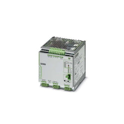
QUINT-UPS/ 1AC/ 1AC/500VA - Uninterruptible power supply with IQ technology 1AC/1AC/500 VA. For 120 V AC/230 V AC applications

Safety relay for emergency stop and safety door monitoring up to SIL 3 or Cat. 4, PL e according to EN ISO 13849, automatic or manual activation, 2 N/O contacts with dropout delay of 0.1 s to 30 s, plug-in screw connection terminal block
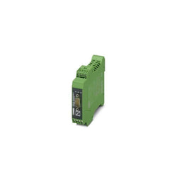
Interface converter, for converting RS-232 (V.24) to RS-422 (V.11) and RS-485, with electrical isolation, 2 channels, rail-mountable
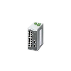
Ethernet Switch, 16 TP RJ45 ports, automatic detection of data transmission speed of 10 or 100 Mbps (RJ45), autocrossing function