
 1 year warranty


metal safety switch XCSE - 2NC+1NO - slow break- 2entries tapped M20- 24V
Discrete input module, Modicon TM3, 16 inputs (screw) 24 VDC

Analog input module, Modicon TM3, 4 / temperature inputs (screw) 24 VDC
Analog output module, Modicon TM3, 4 outputs (screw) 24 VDC
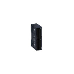
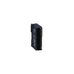
This digital output module is part of the Modicon TM3 range of I/O expansion modules for Modicon controllers It consists in 16 N/O relay outputs 2 A. It is equipped with one removable screw terminal block and can be mounted on a symmetrical DIN rail 35 mm. This digital I/O module complement the embedded I/O on Modicon M221, M221 Book, M241 and M251 logic controllers. There is an insulation between output and internal logic at 2300V AC, outputs at 750V AC, output groups at 1500V AC. It is furnished with removable spring terminal for electrical connection with 5.08mm pitch adjustment for inputs and outputs. It is an IP20 rated product. Its dimensions are 23.6mm (Width) x 70mm (Depth) x 90mm (Height). It weighs 0.14kg. This product is certified by CE. It meets EN/IEC 61131-2 and EN/IEC 61010-2-201 standards. This module is compatible with Modicon M262, Modicon M241, Modicon M251 and Modicon M221 logic controller. It supports top hat type TH35-15, top hat type TH35-7.5 rail conforming to IEC 60715 and plate or panel with fixing kit mount. Modicon TM3 expansion modules have been designed with a simple interlocking assembly mechanism. A bus expansion connector is used to distribute data and the power supply when assembling the Modicon TM3 modules with logic controllers. Boost the performance of your controller with the Modicon TM3 I/O system specially designed for the Modicon M221, M241 and M251 logic controllers.
Main
| Characteristic | Value(s) |
|---|---|
| Range of Product | Modicon TM3 |
| Product or Component Type | Discrete output module |
| Range Compatibility | Modicon M241 Modicon M251 Modicon M221 Modicon M262 |
| Discrete output type | Relay normally open |
| Discrete output number | 16 |
| Discrete output logic | Positive or negative |
| Discrete output voltage | 240 V AC relay output 30 V DC relay output |
| Discrete output current | 2000 mA relay output |
Complementary
| Characteristic | Value(s) |
|---|---|
| Discrete I/O number | 16 |
| Current consumption | 0 mA 24 V DC via bus connector at state off) 75 mA 24 V DC via bus connector at state on) |
| Response time | 10 ms (turn-on) 5 ms (turn-off) |
| Mechanical durability | 20000000 cycles |
| Minimum load | 10 mA 5 V DC relay output |
| Local signalling | 1 LED per channel (green) for output status |
| Electrical connection | 10 x 1.5 mm² removable screw terminal block pitch 3.81 mm for outputs |
| Maximum cable distance between devices | Unshielded cable <98.4 ft (30 m) relay output |
| Insulation | Between output and internal logic 2300 V AC Between outputs 750 V AC Between output groups 1500 V AC |
| Marking | CE |
| Mounting support | Top hat type TH35-15 rail IEC 60715 Top hat type TH35-7.5 rail IEC 60715 plate or panel with fixing kit |
| Height | 3.5 in (90 mm) |
| Depth | 3.3 in (84.6 mm) |
| Width | 1.08 in (27.4 mm) |
| Product Weight | 0.320 lb(US) (0.145 kg) |
Main
| Characteristic | Value(s) |
|---|---|
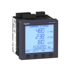
| Range of Product | PowerLogic PM800 |
| Device short name | PM810 |
| Product or Component Type | Power meter |
Complementary
| Characteristic | Value(s) |
|---|---|
| Power quality analysis | Up to the 31st harmonic |
| Type of measurement | Current Voltage Frequency Power factor total Apparent power total Active power total Reactive power total Apparent power per phase Active power per phase Reactive power per phase Energy Power factor per phase |
| supply voltage | 125...250 V DC 115...415 V AC 45...67 Hz 115...415 V AC 350...450 Hz |
| Network Frequency | 350...450 Hz 45...67 Hz |
| Maximum power consumption in VA | 15 VA |
| Display Type | Backlit LCD |
| Display Resolution | 6 lines |
| Sampling rate | 128 samples/cycle |
| Measurement current | 5 A 1 A |
| input type | Current 0.005...10 A (impedance <= 0.1 Ohm) |
| Measurement voltage | 0â¦600 V AC phase to phase 0â¦347 V AC phase to neutral |
| Number of inputs | 1 digital 0...5 mA 24...125 V AC/DC |
| Measurement accuracy | Current 0.5 % 0.5...10 A Voltage 0.2 % 10...227 V Energy 0.2 % Frequency 0.01 Hz Power factor 0.002 Power 0.2 % |
| Accuracy class | Class 2 reactive energy IEC 62053-23 Class 0.5S active energy IEC 62053-22 Class 0.2 active energy ANSI C12.20 |
| Number of Outputs | 1 digital (static) |
| Communication port protocol | Modbus 38.4 kbauds |
| Communication port support | RS485 |
| Data recording | Min/max of instantaneous values Time stamping Without memory Alarms GPS synchronisation |
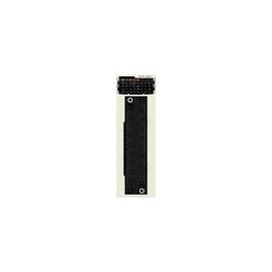
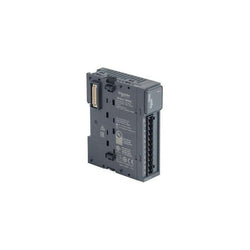
This discrete output module is part of the Modicon X80 modules. It has 16 relay non protected outputs, 24V DC / 24V to 240V AC. This module is connected via 20-way removable terminal block. It occupies a single slot on the rack and it has a case which provides IP 20 protection of the electronics.
Main
| Characteristic | Value(s) |
|---|---|
| Range of Product | Modicon X80 |
| Product or Component Type | Discrete output module |
| Discrete output number | 16 EN/IEC 61131-2 |
| Discrete output type | Relay |
| Discrete output voltage | 24...48 V 19...60 V DC 24...240 V 19â¦264 V AC |
Complementary
| Characteristic | Value(s) |
|---|---|
| [Ith] conventional free air thermal current | 2 A |
| Insulation resistance | > 10 MOhm 500 V DC |
| Power dissipation in W | 3 W |
| Response time on output | < 8 ms activation < 10 ms deactivation |
| Typical current consumption | 100 mA 3.3 V DC 95 mA 24 V DC |
| MTBF reliability | 2100000 H |
| Output overload protection | Use 1 fast blow fuse per channel or group of channel |
| Output overvoltage protection | Use discharge diode on each output DC Use RC circuit on each output AC Use ZNO surge limiter on each output AC |
| Output short-circuit protection | Use 1 fast blow fuse per channel or group of channel |
| Minimum switching current | 1 mA 5 V DC |
| Electrical durability | AC-15 100000 cycles 240 VA 200 V 0.7) AC-15 100000 cycles 120 VA 200 V 0.35) AC-12 100000 cycles 200 VA 100 V AC-12 100000 cycles 80 VA 48 V AC-12 100000 cycles 50 VA 24 V AC-15 100000 cycles 120 VA 100 V AC-15 100000 cycles 120 VA 24 V AC-15 100000 cycles 120 VA 48 V DC-12 100000 cycles 24 W 24 V DC-13 100000 cycles 10 W 24 V DC-13 100000 cycles 10 W 48 V AC-15 300000 cycles 72 VA 200 V 0.7) AC-15 300000 cycles 36 VA 200 V 0.35) AC-12 300000 cycles 200 VA 200 V AC-12 300000 cycles 80 VA 100 V AC-12 300000 cycles 50 VA 48 V AC-15 300000 cycles 36 VA 100 V AC-15 300000 cycles 72 VA 100 V AC-15 300000 cycles 36 VA 48 V AC-15 300000 cycles 72 VA 48 V AC-15 300000 cycles 36 VA 24 V AC-15 300000 cycles 72 VA 24 V DC-13 300000 cycles 3 W 24 V DC-13 300000 cycles 3 W 48 V DC-13 7000 cycles 24 W 24 V DC-13 7000 cycles 24 W 48 V DC-12 50000 cycles 24 W 48 V |
| Status LED | 1 LED (Green) RUN 1 LED per channel (Green) channel diagnostic 1 LED (Red) ERR 1 LED (Red) I/O |
| Product Weight | 0.33 lb(US) (0.15 kg) |
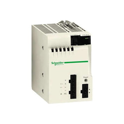
This product is part of the Modicon X80 range, a common platform of modules for Modicon M580 and M340 Programmable Automation Controllers (PAC). This power supply module has an isolated voltage of 24V DC. It is a power supply module with a secondary power of 16.8W at 24V DC, a current at secondary voltage of 2.5A at 3.3V DC and a maximum power dissipation of 8.5W. This product is robust, high quality and based on the latest innovative technology. It is furnished with 2-pin connector for alarm relay, 5-pin connector for line supply, protective earth, 24V DC input sensor for electrical connection. It is an IP20 rated product. It weighs 0.29kg. It is suitable for medium to large process applications. This product is certified by CE, RCM, Merchant Navy, CSA, EAC, UL. It meets EN 61131-2, EN 61000-6-4, EN 61000-6-2 and EN 61010-2-201 standards. Modicon X80 consists in a compatible modules common platform that reduce maintenance and training costs with same spare parts in stock, and unique training for different Programmable Automation Controllers (PAC).
Main
| Characteristic | Value(s) |
|---|---|
| Range of Product | Modicon X80 |
| Product or Component Type | Power supply module |
| backplane compatibility | Not compatible with BMEXBP..02 |
| Primary Voltage | 24 V isolated |
| Supply circuit type | DC |
| Secondary power | 16.8 W 24 V DC I/O module power supply and processor 8.3 W 3.3 V DC I/O module logic power supply |
Complementary
| Characteristic | Value(s) |
|---|---|
| Primary voltage limit | 18...31.2 V |
| Input current | 1 A 24 V |
| Inrush current | 30 A 24 V |
| I²t on activation | 0.6 A².s 24 V |
| It on activation | 0.15 A.s 24 V |
| MTBF reliability | 4886000 H |
| Protection type | Internal fuse not accessible primary circuit Overload protection secondary circuit, 24 V sensor power supply Overvoltage protection secondary circuit, 24 V sensor power supply Short-circuit protection secondary circuit, 24 V sensor power supply |
| Current at secondary voltage | 0.7 A 24 V DC I/O module power supply and processor 2.5 A 3.3 V DC I/O module logic power supply |
| Maximum power dissipation in W | 8.5 W |
| Status LED | 1 LED (Green) rack voltage OK |
| Control Type | RESET push-button cold restart |
| Electrical connection | 1 connector 2 alarm relay 1 connector 5 line supply, protective earth, 24 V DC input sensor |
| Maximum cable distance between devices | 65.6 ft (20 m) power supply cable copper 0.002 in² (1.5 mm²) 98.4 ft (30 m) power supply cable copper 0.004 in² (2.5 mm²) |
| Insulation resistance | >= 10 MOhm primary/ground >= 10 MOhm primary/secondary |
| Product Weight | 0.64 lb(US) (0.29 kg) |

Variable Speed Drive Altivar 71 - 3kW-480V - with EMC filter whitout Graphic Terminal
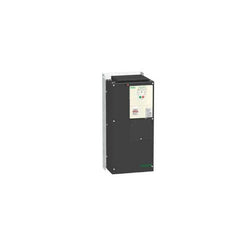
Variable Speed Drive Altivar ATV212 - 45kW - 60hp - 480V - 3ph - EMC - IP21
This Altivar 212 variable speed drive can feed 3-phase asynchronous motors. Its protection index is IP21 and it has a built-in EMC filter. It works at a rated power up to 30kW / 40hp and a rated voltage from 380V to 480V AC. Its design is based on eco-energy with a reduction in energy consumption of up to 70% compared to a conventional control system. Thanks to its cable temperature rise reduction technology, the Altivar 212 drive offers immediate, disturbance-free operation avoiding additional options such as a line choke or DC choke to deal with current harmonics. It weighs 26.4kg and its dimensions are, 240mm wide, 420mm high, 214mm deep. It is specifically designed for the most common fluid management applications in tertiary sector buildings (HVAC) like heating, ventilation, air conditioning and pumping. It conforms to international standards IEC/EN 61800-5-1 and IEC/EN 61800-3 (immunity and conducted and radiated EMC emissions). It is also CE, UL, CSA, C-Tick and NOM certified. The Altivar 212 offers optional motor chokes which can increase the maximum cable lengths between the drive and the motor and limit disturbance at the motor terminals. It is designed to be mounted in vertical position (+/- 10 °) on a panel, thanks to 4 fixing holes. The Altivar 212 drive can easily be adapted to all building management systems thanks to its numerous functions and communication protocols integrated as standard, Modbus, METASYS N2, APOGEE FLN P1 and BACnet.
Main
| Characteristic | Value(s) |
|---|---|
| Device short name | ATV212 |
| Product destination | Asynchronous motors |
| Phase | 3 phase |
| Motor power kW | 30 kW |
| Maximum Horse Power Rating | 40 hp |
| Supply voltage limits | 323â¦528 V |
| Supply frequency | 50...60 Hz - 5...5 % |
| Line current | 44.7 A 480 V 56.7 A 380 V |
| Range of Product | Altivar 212 |
| Product or Component Type | Variable speed drive |
| Product Specific Application | Pumps and fans in HVAC |
| Communication Port Protocol | APOGEE FLN Modbus BACnet METASYS N2 LonWorks |
| [Us] rated supply voltage | 380...480 V - 15...10 % |
| EMC filter | Class C2 EMC filter integrated |
| IP degree of protection | IP21 |
Complementary
| Characteristic | Value(s) |
|---|---|
| Apparent power | 44.6 kVA 380 V |
| Continuous output current | 58.5 A 380 V 58.5 A 460 V |
| Maximum transient current | 64.4 A 60 s |
| Speed drive output frequency | 0.5â¦200 Hz |
| Speed range | 1â¦10 |
| Speed accuracy | +/- 10 % of nominal slip 0.2 Tn to Tn |
| Local signalling | 1 LED (red) for DC bus energized |
| Output voltage | <= power supply voltage |
| Isolation | Electrical between power and control |
| Type of cable | Without mounting kit 1 IEC cable 113 °F (45 °C), copper 90 °C / XLPE/EPR Without mounting kit 1 IEC cable 113 °F (45 °C), copper 70 °C / PVC With UL Type 1 kit 3 UL 508 cable 104 °F (40 °C), copper 75 °C / PVC |
| Electrical connection | VIA, VIB, FM, FLA, FLB, FLC, RY, RC, F, R, RES terminal 0.004 in² (2.5 mm²) / AWG 14 L1/R, L2/S, L3/T terminal 0.08 in² (50 mm²) / AWG 1/0 |
| Tightening torque | 5.3 lbf.in (0.6 N.m) VIA, VIB, FM, FLA, FLB, FLC, RY, RC, F, R, RES) 212.4 lbf.in (24 N.m), 212 lb.in L1/R, L2/S, L3/T) |
| Supply | Internal supply for reference potentiometer (1 to 10 kOhm) 10.5 V DC +/- 5 %, <10 A overload and short-circuit protection Internal supply 24 V DC 21â¦27 V), <200 A overload and short-circuit protection |
| Sampling duration | 2 ms +/- 0.5 ms F discrete 2 ms +/- 0.5 ms R discrete 2 ms +/- 0.5 ms RES discrete 3.5 ms +/- 0.5 ms VIA analog 22 ms +/- 0.5 ms VIB analog |
| Response time | FM 2 ms +/- 0.5 ms analog FLA, FLC 7 ms +/- 0.5 ms discrete FLB, FLC 7 ms +/- 0.5 ms discrete RY, RC 7 ms +/- 0.5 ms discrete |
| Accuracy | +/- 0.6 % VIA) for a temperature variation 60 °C +/- 0.6 % VIB) for a temperature variation 60 °C +/- 1 % FM) for a temperature variation 60 °C |
| Linearity error | VIA +/- 0.15 % of maximum value input VIB +/- 0.15 % of maximum value input FM +/- 0.2 % output |
| Analogue output type | FM switch-configurable voltage 0...10 V DC 7620 Ohm 10 bits FM switch-configurable current 0...20 mA 970 Ohm 10 bits |
| Discrete output type | Configurable relay logic FLA, FLC) NO - 100000 cycles Configurable relay logic FLB, FLC) NC - 100000 cycles Configurable relay logic RY, RC) NO - 100000 cycles |
| Minimum switching current | 3 mA 24 V DC configurable relay logic |
| Maximum switching current | 5 A 250 V AC resistive cos phi = 1 L/R = 0 ms FL, R) 5 A 30 V DC resistive cos phi = 1 L/R = 0 ms FL, R) 2 A 250 V AC inductive cos phi = 0.4 L/R = 7 ms FL, R) 2 A 30 V DC inductive cos phi = 0.4 L/R = 7 ms FL, R) |
| Discrete input type | F programmable 24 V DC level 1 PLC 4700 Ohm R programmable 24 V DC level 1 PLC 4700 Ohm RES programmable 24 V DC level 1 PLC 4700 Ohm |
| Discrete input logic | Positive logic (source) F, R, RES), <= 5 V, >= 11 V Negative logic (sink) F, R, RES), >= 16 V, <= 10 V |
| Dielectric strength | 3535 V DC between earth and power terminals 5092 V DC between control and power terminals |
| Insulation resistance | >= 1 mOhm 500 V DC for 1 minute |
| Frequency resolution | Display unit 0.1 Hz Analog input 0.024/50 Hz |
| Communication Service | Read device identification (43) Monitoring inhibitable Time out setting from 0.1 to 100 s Read holding registers (03) 2 words maximum Write single register (06) Write multiple registers (16) 2 words maximum |
| Option card | Communication card LonWorks |
| Power dissipation in W | 847 W |
| air flow | 76611.3 Gal/hr(US) (290 m3/h) |
| Functionality | Mid |
| Specific application | HVAC |
| Variable speed drive application selection | Building - HVAC compressor for scroll Building - HVAC fan Building - HVAC pump |
| Motor power range AC-3 | 30â¦50 kW 380â¦440 V 3 phase 30â¦50 kW 480â¦500 V 3 phase |
| Motor starter type | Variable speed drive |
| Discrete output number | 2 |
| Analogue input number | 2 |
| Analogue input type | VIA switch-configurable voltage 0...10 V DC 24 V max 30000 Ohm 10 bits VIB configurable voltage 0...10 V DC 24 V max 30000 Ohm 10 bits VIB configurable PTC probe 0...6 probes 1500 Ohm VIA switch-configurable current 0...20 mA 250 Ohm 10 bits |
| Analogue output number | 1 |
| Physical interface | 2-wire RS 485 |
| Connector Type | 1 open style 1 RJ45 |
| Transmission Rate | 9600 bps or 19200 bps |
| Transmission frame | RTU |
| Number of addresses | 1â¦247 |
| Data format | 8 bits, 1 stop, odd even or no configurable parity |
| Type of polarization | No impedance |
| Asynchronous motor control profile | Voltage/frequency ratio, automatic IR compensation (U/f + automatic Uo) Flux vector control without sensor, standard Voltage/frequency ratio, 5 points Voltage/frequency ratio - Energy Saving, quadratic U/f Voltage/frequency ratio, 2 points |
| Torque accuracy | +/- 15 % |
| Transient overtorque | 120 % of nominal motor torque +/- 10 % 60 s |
| Acceleration and deceleration ramps | Linear adjustable separately from 0.01 to 3200 s Automatic based on the load |
| Motor slip compensation | Not available in voltage/frequency ratio motor control Automatic whatever the load Adjustable |
| Switching frequency | 6...16 kHz adjustable 8...16 kHz with derating factor |
| Nominal switching frequency | 8 kHz |
| Braking to standstill | By DC injection |
| Network Frequency | 47.5...63 Hz |
| Prospective line Isc | 22 kA |
| Protection type | Overheating protection drive Thermal power stage drive Short-circuit between motor phases drive Input phase breaks drive Overcurrent between output phases and earth drive Overvoltages on the DC bus drive Break on the control circuit drive Against exceeding limit speed drive Line supply overvoltage and undervoltage drive Line supply undervoltage drive Against input phase loss drive Thermal protection motor Motor phase break motor With PTC probes motor |
| Width | 9.4 in (240 mm) |
| Height | 16.5 in (420 mm) |
| Depth | 8.4 in (214 mm) |
| Product Weight | 58.2 lb(US) (26.4 kg) |

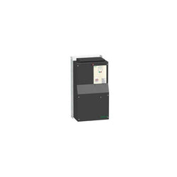
This Altivar 212 variable speed drive can feed 3-phase asynchronous motors. Its protection index is IP21 and it has a built-in EMC filter. It works at a rated power up to 0.75kW / 1hp and a rated voltage from 380V to 480V AC. Its design is based on eco-energy with a reduction in energy consumption of up to 70% compared to a conventional control system. Thanks to its cable temperature rise reduction technology, the Altivar 212 drive offers immediate, disturbance-free operation avoiding additional options such as a line choke or DC choke to deal with current harmonics. It weighs 2kg and its dimensions are, 107mm wide, 143mm high, 150mm deep. It is specifically designed for the most common fluid management applications in tertiary sector buildings (HVAC) like heating, ventilation, air conditioning and pumping. It conforms to international standards IEC/EN 61800-5-1 and IEC/EN 61800-3 (immunity and conducted and radiated EMC emissions). It is also CE, UL, CSA, C-Tick and NOM certified. The Altivar 212 offers optional motor chokes which can increase the maximum cable lengths between the drive and the motor and limit disturbance at the motor terminals. It is designed to be mounted in vertical position (+/- 10 °) on a panel, thanks to 4 fixing holes. It can also be mounted directly on a 35 mm wide DIN rail, thanks to the kit VW3A31852, to order separately. The Altivar 212 drive can easily be adapted to all building management systems thanks to its numerous functions and communication protocols integrated as standard, Modbus, METASYS N2, APOGEE FLN P1 and BACnet.
Main
| Characteristic | Value(s) |
|---|---|
| Device short name | ATV212 |
| Product destination | Asynchronous motors |
| Phase | 3 phase |
| Motor power kW | 0.75 kW |
| Maximum Horse Power Rating | 1 hp |
| Supply voltage limits | 323â¦528 V |
| Supply frequency | 50...60 Hz - 5...5 % |
| Line current | 1.4 A 480 V 1.7 A 380 V |
| Range of Product | Altivar 212 |
| Product or Component Type | Variable speed drive |
| Product Specific Application | Pumps and fans in HVAC |
| Communication Port Protocol | Modbus METASYS N2 APOGEE FLN LonWorks BACnet |
| [Us] rated supply voltage | 380...480 V - 15...10 % |
| EMC filter | Class C2 EMC filter integrated |
| IP degree of protection | IP21 |
Complementary
| Characteristic | Value(s) |
|---|---|
| Apparent power | 1.6 kVA 380 V |
| Continuous output current | 2.2 A 380 V 2.2 A 460 V |
| Maximum transient current | 2.4 A 60 s |
| Speed drive output frequency | 0.5â¦200 Hz |
| Speed range | 1â¦10 |
| Speed accuracy | +/- 10 % of nominal slip 0.2 Tn to Tn |
| Local signalling | 1 LED (red) for DC bus energized |
| Output voltage | <= power supply voltage |
| Isolation | Electrical between power and control |
| Type of cable | Without mounting kit 1 IEC cable 113 °F (45 °C), copper 90 °C / XLPE/EPR Without mounting kit 1 IEC cable 113 °F (45 °C), copper 70 °C / PVC With UL Type 1 kit 3 UL 508 cable 104 °F (40 °C), copper 75 °C / PVC |
| Electrical connection | VIA, VIB, FM, FLA, FLB, FLC, RY, RC, F, R, RES terminal 0.004 in² (2.5 mm²) / AWG 14 L1/R, L2/S, L3/T terminal 0.009 in² (6 mm²) / AWG 10 |
| Tightening torque | 11.5 lbf.in (1.3 N.m), 11.5 lb.in L1/R, L2/S, L3/T) 5.3 lbf.in (0.6 N.m) VIA, VIB, FM, FLA, FLB, FLC, RY, RC, F, R, RES) |
| Supply | Internal supply for reference potentiometer (1 to 10 kOhm) 10.5 V DC +/- 5 %, <10 A overload and short-circuit protection Internal supply 24 V DC 21â¦27 V), <200 A overload and short-circuit protection |
| Sampling duration | 2 ms +/- 0.5 ms F discrete 2 ms +/- 0.5 ms R discrete 2 ms +/- 0.5 ms RES discrete 3.5 ms +/- 0.5 ms VIA analog 22 ms +/- 0.5 ms VIB analog |
| Response time | FM 2 ms +/- 0.5 ms analog FLA, FLC 7 ms +/- 0.5 ms discrete FLB, FLC 7 ms +/- 0.5 ms discrete RY, RC 7 ms +/- 0.5 ms discrete |
| Accuracy | +/- 0.6 % VIA) for a temperature variation 60 °C +/- 0.6 % VIB) for a temperature variation 60 °C +/- 1 % FM) for a temperature variation 60 °C |
| Linearity error | VIA +/- 0.15 % of maximum value input VIB +/- 0.15 % of maximum value input FM +/- 0.2 % output |
| Analogue output type | FM switch-configurable voltage 0...10 V DC 7620 Ohm 10 bits FM switch-configurable current 0...20 mA 970 Ohm 10 bits |
| Discrete output type | Configurable relay logic FLA, FLC) NO - 100000 cycles Configurable relay logic FLB, FLC) NC - 100000 cycles Configurable relay logic RY, RC) NO - 100000 cycles |
| Minimum switching current | 3 mA 24 V DC configurable relay logic |
| Maximum switching current | 5 A 250 V AC resistive cos phi = 1 L/R = 0 ms FL, R) 5 A 30 V DC resistive cos phi = 1 L/R = 0 ms FL, R) 2 A 250 V AC inductive cos phi = 0.4 L/R = 7 ms FL, R) 2 A 30 V DC inductive cos phi = 0.4 L/R = 7 ms FL, R) |
| Discrete input type | F programmable 24 V DC level 1 PLC 4700 Ohm R programmable 24 V DC level 1 PLC 4700 Ohm RES programmable 24 V DC level 1 PLC 4700 Ohm |
| Discrete input logic | Positive logic (source) F, R, RES), <= 5 V, >= 11 V Negative logic (sink) F, R, RES), >= 16 V, <= 10 V |
| Dielectric strength | 3535 V DC between earth and power terminals 5092 V DC between control and power terminals |
| Insulation resistance | >= 1 mOhm 500 V DC for 1 minute |
| Frequency resolution | Display unit 0.1 Hz Analog input 0.024/50 Hz |
| Communication Service | Read device identification (43) Time out setting from 0.1 to 100 s Write single register (06) Write multiple registers (16) 2 words maximum Monitoring inhibitable Read holding registers (03) 2 words maximum |
| Option card | Communication card LonWorks |
| Power dissipation in W | 55 W |
| air flow | 5019.4 Gal/hr(US) (19 m3/h) |
| Functionality | Mid |
| Specific application | HVAC |
| Variable speed drive application selection | Building - HVAC compressor for scroll Building - HVAC fan Building - HVAC pump |
| Motor power range AC-3 | 0.55â¦1 kW 380â¦440 V 3 phase 0.55â¦1 kW 480â¦500 V 3 phase |
| Motor starter type | Variable speed drive |
| Discrete output number | 2 |
| Analogue input number | 2 |
| Analogue input type | VIA switch-configurable voltage 0...10 V DC 24 V max 30000 Ohm 10 bits VIB configurable voltage 0...10 V DC 24 V max 30000 Ohm 10 bits VIB configurable PTC probe 0...6 probes 1500 Ohm VIA switch-configurable current 0...20 mA 250 Ohm 10 bits |
| Analogue output number | 1 |
| Physical interface | 2-wire RS 485 |
| Connector Type | 1 open style 1 RJ45 |
| Transmission Rate | 9600 bps or 19200 bps |
| Transmission frame | RTU |
| Number of addresses | 1â¦247 |
| Data format | 8 bits, 1 stop, odd even or no configurable parity |
| Type of polarization | No impedance |
| Asynchronous motor control profile | Voltage/frequency ratio, automatic IR compensation (U/f + automatic Uo) Voltage/frequency ratio - Energy Saving, quadratic U/f Voltage/frequency ratio, 2 points Flux vector control without sensor, standard Voltage/frequency ratio, 5 points |
| Torque accuracy | +/- 15 % |
| Transient overtorque | 120 % of nominal motor torque +/- 10 % 60 s |
| Acceleration and deceleration ramps | Automatic based on the load Linear adjustable separately from 0.01 to 3200 s |
| Motor slip compensation | Not available in voltage/frequency ratio motor control Automatic whatever the load Adjustable |
| Switching frequency | 6...16 kHz adjustable 12...16 kHz with derating factor |
| Nominal switching frequency | 12 kHz |
| Braking to standstill | By DC injection |
| Network Frequency | 47.5...63 Hz |
| Prospective line Isc | 5 kA |
| Protection type | Overheating protection drive Thermal power stage drive Short-circuit between motor phases drive Input phase breaks drive Overcurrent between output phases and earth drive Overvoltages on the DC bus drive Break on the control circuit drive Against exceeding limit speed drive Line supply overvoltage and undervoltage drive Line supply undervoltage drive Against input phase loss drive Thermal protection motor Motor phase break motor With PTC probes motor |
| Width | 4.2 in (107 mm) |
| Height | 5.6 in (143 mm) |
| Depth | 5.9 in (150 mm) |
| Product Weight | 4.4 lb(US) (2 kg) |

GP PRO EX SOFTWARE - 4.XX VERSION
Main
| Characteristic | Value(s) |
|---|---|
| Range of Product | Modicon Quantum automation platform |
| Product or Component Type | Processor |
| Software name | ProWORX 32 Concept |
| Processor name | 80486 |
| Mathematical coprocessor | With |
Complementary
| Characteristic | Value(s) |
|---|---|
| Clock frequency | 100 MHz |
| Memory description | Internal RAM 2972 kB |
| Exact time for 1 Kinstruction | 0.1...0.5 ms LL984 |
| Watchdog timer | 250 ms |
| Clock drift | +/-8 s/day 32â¦140 °F (0â¦60 °C) |
| I/O words | 30 I/32 O distributed 64 I/64 O max local 64 I/64 O remote |
| I/O words/network | 500 I/500 O distributed |
| Drops/network | 63 distributed |
| Number of drops | 31 remote |
| Number of network | 2 remote 3 distributed |
| Battery type | Lithium 10 µA 420 µA |
| Battery Capacity | 1.2 Ah |
| Battery life | 10 year(s) |
| Switch Function | Key switch |
| Marking | CE |
| Bus current requirement | 1250 mA |
| Module format | Standard |
| Product Weight | 1.87 lb(US) (0.85 kg) |

This Basic HMI panel belongs to the Pro-face ST6000 range. This single touch resistive HMI is made of alluminium front panel with higher resolution and more color. This HMI interface is 12.1 inch wide with 16 million colors and 1,280 x 800 pixel resolution (WXGA). It is powered by GP-ProEX software for easy migration. It has a 800 MHz ARM Cortex-A8 CPU, 64MB as application memory, 320KB for screen area and 64KB for variable area as backup memory. This HMI ST6000 supports 2x Ethernet port, COM1 (RS-232C), COM2 (RS-485), 1x USB 2.0 Type A, and 1x USB 2.0 Micro-B port. Its dimensions are 313mm (width) x 235mm (height) x 50mm (depth) and weighs 1.80Kg. This is intended for indsutries like packaging, food & beverage, textile, HVAC equipment, and compressors, and also for GP4000 Series W model user looking for modernize their machine with the same application. It conforms to standards like EN (61000-6-4, 61000-6-2, 61131-2), UL 61010-2-201, CSA C22.2 No 61010-2-201 and certifications like CSA, CE, China RoHS, KC, REACH. This range is designed to meet the needs of simple machine operators for good visualization, connectivity, cybersecurity with Pro-face Connect and cost effective equipment. The various degree of protection are IP65F, Type 1, Type 4X (indoor use only), Type 13 (on the front panel when properly installed in an enclosure).

This Basic HMI panel belongs to the Pro-face ST6000 range. This single touch resistive HMI is made of alluminium front panel with higher resolution and more color. This HMI interface is 10.1 inch wide with 16 million colors and 1024 x 600 pixel resolution (SVGA). It is powered by GP-ProEX software for easy migration. It has a 800 MHz ARM Cortex-A8 CPU, 64MB as application memory, 320KB for screen area and 64KB for variable area as backup memory. This HMI ST6000 supports 2x Ethernet port, COM1 (RS-232C), COM2 (RS-485), 1x USB 2.0 Type A, and 1x USB 2.0 Micro-B port. Its dimensions are 273mm (width) x 203mm (height) x 47mm (depth) and weighs 1.30Kg. This is intended for indsutries like packaging, food & beverage, textile, HVAC equipment, and compressors, and also for GP4000 Series W model user looking for modernize their machine with the same application. It conforms to standards like EN (61000-6-4, 61000-6-2, 61131-2), UL 61010-2-201, CSA C22.2 No 61010-2-201 and certifications like CSA, CE, China RoHS, KC, REACH. This range is designed to meet the needs of simple machine operators for good visualization, connectivity, cybersecurity with Pro-face Connect and cost effective equipment. The various degree of protection are IP65F, Type 1, Type 4X (indoor use only), Type 13 (on the front panel when properly installed in an enclosure).

10.4 Touch Panel

7.5 Touch Panel

GP4000E Series 7'' Touch Screen HMI Panel
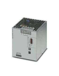
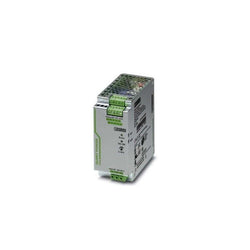
Primary-switched QUINT POWER power supply with free choice of output characteristic curve, SFB�(selective fuse breaking) technology, and NFC interface, input: 3-phase,�output:�24�V�DC/40�A
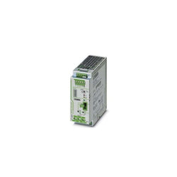
Uninterruptible power supply with IQ technology for DIN rail mounting, input: 24 V DC, output: 24 V DC/40 A, including mounted universal DIN rail adapter UTA 107/30
QUINT UPS with IQ Technology, for DIN rail mounting, input: 24�V�DC, output: 24�V�DC�/�40�A, charging current: 5�A
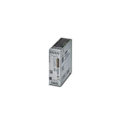
Primary-switched QUINT POWER power supply for DIN rail mounting with SFB (Selective Fuse Breaking) Technology, input: 1-phase, output: 12 V DC/15 A
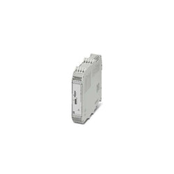
MACX MCR voltage transducer, for AC voltages from 0 V ... 20 V AC to 0 ... 660 V AC, output signal: 0 V ... 10 V/0(4) ... 20 mA