
 1 year warranty


Ordering
1 piece
85365080
Popular Downloads
Dimensions
18 mm
65 mm
85 mm
0.14 kg
Technical
2
0
0
0
2P
IEC/EN 60947-1
IEC/EN 60947-4-1
UL 60947-1
UL 60947-4-1
IEC/EN 61095
IEC 60335-2-40 A2L
IEC/EN 60947-1
IEC/EN 60947-4-1
UL 60947-1
UL 60947-4-1
IEC/EN 61095
IEC 60335-2-40 A2L
Main Circuit 220 V DC
Main Circuit 250 V AC
Main Circuit 220 V DC
Main Circuit 250 V AC
Control Circuit DC
Control Circuit 50 Hz
Control Circuit 60 Hz
Control Circuit 400 Hz
Main Circuit DC
Main Circuit 50 Hz
Main Circuit 60 Hz
Control Circuit DC
Control Circuit 50 Hz
Control Circuit 60 Hz
Control Circuit 400 Hz
Main Circuit DC
Main Circuit 50 Hz
Main Circuit 60 Hz
(NO) 20 A
(230 V) Single Phase, NO 9 A
(NO) 20 A
(230 V) Single Phase, NO 9 A
(230 V) Single Phase, NO 4.6 kW
(230 V) Single Phase, NO 1.3 kW
(230 V) Single Phase, NO 4.6 kW
(230 V) Single Phase, NO 1.3 kW
8 x Ie / AC-3
10 x Ie / AC-3
at 40 °C Ambient Temp, in Free Air, from a Cold State 10 s 72 A
400 V
6 kV
AC-1 (NO) 150000 cycle
AC-3 (NO) 150000 cycle
AC-7a (NO) 150000 cycle
AC-7b (NO) 150000 cycle
AC-1 (NO) 150000 cycle
AC-3 (NO) 150000 cycle
AC-7a (NO) 150000 cycle
AC-7b (NO) 150000 cycle
(AC-1) 300 cycles per hour
(AC-3) 600 cycles per hour
(AC-7a) 300 cycles per hour
(AC-7b) 600 cycles per hour
(AC-1) 300 cycles per hour
(AC-3) 600 cycles per hour
(AC-7a) 300 cycles per hour
(AC-7b) 600 cycles per hour
Nr. Operations 1000000 cycle
(acc. to IEC 60947-4-1) 0.85 ... 1.1 x Uc (at θ ≤ 55 °C)
240 V
Average Holding Value 50 / 60 Hz 2.5 V·A
Average Holding Value DC 2.5 W
Average Pull-in Value 50 Hz 2.5 V·A
Average Pull-in Value 60 Hz 2.5 V·A
Average Pull-in Value DC 2.5 W
Average Holding Value 50 / 60 Hz 2.5 V·A
Average Holding Value DC 2.5 W
Average Pull-in Value 50 Hz 2.5 V·A
Average Pull-in Value 60 Hz 2.5 V·A
Average Pull-in Value DC 2.5 W
at Rated Operating Conditions AC-1 per Pole 1.4 W
TH35-15 (35 x 15 mm Mounting Rail) acc. to IEC 60715
TH35-7.5 (35 x 7.5 mm Mounting Rail) acc. to IEC 60715
TH35-15 (35 x 15 mm Mounting Rail) acc. to IEC 60715
TH35-7.5 (35 x 7.5 mm Mounting Rail) acc. to IEC 60715
Flexible with Ferrule 1x 1 ... 6 mm²
Flexible with Ferrule 2x 1 ... 2.5 mm²
Flexible with Insulated Ferrule 1x 1 ... 6 mm²
Flexible with Insulated Ferrule 2x 1 ... 1.5 mm²
Flexible 1x 1 ... 6 mm²
Flexible 2x 1 ... 4 mm²
Rigid 1x 1 ... 10 mm²
Rigid 2x 1 ... 4 mm²
Flexible with Ferrule 1x 1 ... 6 mm²
Flexible with Ferrule 2x 1 ... 2.5 mm²
Flexible with Insulated Ferrule 1x 1 ... 6 mm²
Flexible with Insulated Ferrule 2x 1 ... 1.5 mm²
Flexible 1x 1 ... 6 mm²
Flexible 2x 1 ... 4 mm²
Rigid 1x 1 ... 10 mm²
Rigid 2x 1 ... 4 mm²
Flexible with Ferrule 1x 1 ... 2.5 mm²
Flexible with Ferrule 2x 0.75 ... 1.5 mm²
Flexible with Insulated Ferrule 1x 1 ... 2.5 mm²
Flexible with Insulated Ferrule 2x 0.75 ... 1 mm²
Flexible 1x 1 ... 2.5 mm²
Flexible 2x 1 ... 1.5 mm²
Rigid 1x 0.5 ... 4 mm²
Rigid 2x 0.75 ... 2.5 mm²
Flexible with Ferrule 1x 1 ... 2.5 mm²
Flexible with Ferrule 2x 0.75 ... 1.5 mm²
Flexible with Insulated Ferrule 1x 1 ... 2.5 mm²
Flexible with Insulated Ferrule 2x 0.75 ... 1 mm²
Flexible 1x 1 ... 2.5 mm²
Flexible 2x 1 ... 1.5 mm²
Rigid 1x 0.5 ... 4 mm²
Rigid 2x 0.75 ... 2.5 mm²
Control Circuit 7 mm
Main Circuit 10 mm
Control Circuit 7 mm
Main Circuit 10 mm
IP20
Control Circuit Pozidriv 1
Main Circuit Pozidriv 1
Control Circuit Pozidriv 1
Main Circuit Pozidriv 1
Control Circuit 0.9 N·m
Main Circuit 1.2 N·m
Control Circuit 0.9 N·m
Main Circuit 1.2 N·m
Screw Terminals
1.0
Installation Contactor
Technical UL/CSA
Main Circuit 240 V AC
(acc. to UL 240 V) 20 A
(220 ... 240 V AC) Single Phase, NO 1 Hp
Solid 14-8 AWG
Stranded 14-8 AWG
Solid 14-8 AWG
Stranded 14-8 AWG
Solid 16-10 AWG
Stranded 16-10 AWG
Solid 16-10 AWG
Stranded 16-10 AWG
Control Circuit 8 in·lb
Main Circuit 11 in·lb
Control Circuit 8 in·lb
Main Circuit 11 in·lb
(220 ... 240 V AC) Single Phase, NO 8 A
Environmental
Operation -25 ... +55 °C
Storage -40 ... +80 °C
Operation -25 ... +55 °C
Storage -40 ... +80 °C
2000 m
11 ms Pulse 15g
3
Material Compliance
Following EU Directive 2011/65/EU and Amendment 2015/863 July 22, 2019
Business To Consumer
5. Small Equipment (No External Dimension More Than 50 cm)
ABB EcoSolutions
Yes
No non-hazardous waste is sent to a landfill
Certificates and Declarations
Container Information
box 1 piece
88 mm
20 mm
71 mm
0.14 kg
3471523004634
External Classifications and Standards
Q
EC001653 - Installation contactor for distribution board
EC001653 - Installation contactor for distribution board
EC001653 - Installation contactor for distribution board
V11.0 : 27142308
39121529
4759 >> Installation contactor for distribution board
Ordering
1 piece
85365080
Popular Downloads
Dimensions
18 mm
65 mm
85 mm
0.14 kg
Technical
0
2
0
0
2P
IEC/EN 60947-1
IEC/EN 60947-4-1
UL 60947-1
UL 60947-4-1
IEC/EN 61095
IEC 60335-2-40 A2L
IEC/EN 60947-1
IEC/EN 60947-4-1
UL 60947-1
UL 60947-4-1
IEC/EN 61095
IEC 60335-2-40 A2L
Main Circuit 220 V DC
Main Circuit 250 V AC
Main Circuit 220 V DC
Main Circuit 250 V AC
Control Circuit DC
Control Circuit 50 Hz
Control Circuit 60 Hz
Control Circuit 400 Hz
Main Circuit DC
Main Circuit 50 Hz
Main Circuit 60 Hz
Control Circuit DC
Control Circuit 50 Hz
Control Circuit 60 Hz
Control Circuit 400 Hz
Main Circuit DC
Main Circuit 50 Hz
Main Circuit 60 Hz
(NC) 20 A
(230 V) Single Phase, NC 9 A
(NC) 20 A
(230 V) Single Phase, NC 9 A
(230 V) Single Phase, NC 4.6 kW
(230 V) Single Phase, NC 1.3 kW
(230 V) Single Phase, NC 4.6 kW
(230 V) Single Phase, NC 1.3 kW
8 x Ie / AC-3
10 x Ie / AC-3
at 40 °C Ambient Temp, in Free Air, from a Cold State 10 s 72 A
400 V
6 kV
AC-1 (NC) 150000 cycle
AC-3 (NC) 150000 cycle
AC-7a (NC) 150000 cycle
AC-1 (NC) 150000 cycle
AC-3 (NC) 150000 cycle
AC-7a (NC) 150000 cycle
(AC-1) 300 cycles per hour
(AC-3) 600 cycles per hour
(AC-7a) 300 cycles per hour
(AC-7b) 600 cycles per hour
(AC-1) 300 cycles per hour
(AC-3) 600 cycles per hour
(AC-7a) 300 cycles per hour
(AC-7b) 600 cycles per hour
Nr. Operations 1000000 cycle
(acc. to IEC 60947-4-1) 0.85 ... 1.1 x Uc (at θ ≤ 55 °C)
230 V
Average Holding Value 50 / 60 Hz 2.5 V·A
Average Holding Value DC 2.5 W
Average Pull-in Value 50 Hz 2.5 V·A
Average Pull-in Value 60 Hz 2.5 V·A
Average Pull-in Value DC 2.5 W
Average Holding Value 50 / 60 Hz 2.5 V·A
Average Holding Value DC 2.5 W
Average Pull-in Value 50 Hz 2.5 V·A
Average Pull-in Value 60 Hz 2.5 V·A
Average Pull-in Value DC 2.5 W
at Rated Operating Conditions AC-1 per Pole 1.4 W
TH35-15 (35 x 15 mm Mounting Rail) acc. to IEC 60715
TH35-7.5 (35 x 7.5 mm Mounting Rail) acc. to IEC 60715
TH35-15 (35 x 15 mm Mounting Rail) acc. to IEC 60715
TH35-7.5 (35 x 7.5 mm Mounting Rail) acc. to IEC 60715
Flexible with Ferrule 1x 1 ... 6 mm²
Flexible with Ferrule 2x 1 ... 2.5 mm²
Flexible with Insulated Ferrule 1x 1 ... 6 mm²
Flexible with Insulated Ferrule 2x 1 ... 1.5 mm²
Flexible 1x 1 ... 6 mm²
Flexible 2x 1 ... 4 mm²
Rigid 1x 1 ... 10 mm²
Rigid 2x 1 ... 4 mm²
Flexible with Ferrule 1x 1 ... 6 mm²
Flexible with Ferrule 2x 1 ... 2.5 mm²
Flexible with Insulated Ferrule 1x 1 ... 6 mm²
Flexible with Insulated Ferrule 2x 1 ... 1.5 mm²
Flexible 1x 1 ... 6 mm²
Flexible 2x 1 ... 4 mm²
Rigid 1x 1 ... 10 mm²
Rigid 2x 1 ... 4 mm²
Flexible with Ferrule 1x 1 ... 2.5 mm²
Flexible with Ferrule 2x 0.75 ... 1.5 mm²
Flexible with Insulated Ferrule 1x 1 ... 2.5 mm²
Flexible with Insulated Ferrule 2x 0.75 ... 1 mm²
Flexible 1x 1 ... 2.5 mm²
Flexible 2x 1 ... 1.5 mm²
Rigid 1x 0.5 ... 4 mm²
Rigid 2x 0.75 ... 2.5 mm²
Flexible with Ferrule 1x 1 ... 2.5 mm²
Flexible with Ferrule 2x 0.75 ... 1.5 mm²
Flexible with Insulated Ferrule 1x 1 ... 2.5 mm²
Flexible with Insulated Ferrule 2x 0.75 ... 1 mm²
Flexible 1x 1 ... 2.5 mm²
Flexible 2x 1 ... 1.5 mm²
Rigid 1x 0.5 ... 4 mm²
Rigid 2x 0.75 ... 2.5 mm²
Control Circuit 7 mm
Main Circuit 10 mm
Control Circuit 7 mm
Main Circuit 10 mm
IP20
Control Circuit Pozidriv 1
Main Circuit Pozidriv 1
Control Circuit Pozidriv 1
Main Circuit Pozidriv 1
Control Circuit 0.9 N·m
Main Circuit 1.2 N·m
Control Circuit 0.9 N·m
Main Circuit 1.2 N·m
Screw Terminals
1.0
Installation Contactor
Technical UL/CSA
Main Circuit 240 V AC
(acc. to UL 240 V) 20 A
(220 ... 240 V AC) Single Phase, NC 1 Hp
Solid 14-8 AWG
Stranded 14-8 AWG
Solid 14-8 AWG
Stranded 14-8 AWG
Solid 16-10 AWG
Stranded 16-10 AWG
Solid 16-10 AWG
Stranded 16-10 AWG
Control Circuit 8 in·lb
Main Circuit 11 in·lb
Control Circuit 8 in·lb
Main Circuit 11 in·lb
(220 ... 240 V AC) Single Phase, NC 8 A
Environmental
Operation -25 ... +55 °C
Storage -40 ... +80 °C
Operation -25 ... +55 °C
Storage -40 ... +80 °C
2000 m
11 ms Pulse 15g
3
Material Compliance
Following EU Directive 2011/65/EU and Amendment 2015/863 July 22, 2019
Business To Consumer
5. Small Equipment (No External Dimension More Than 50 cm)
ABB EcoSolutions
Yes
No non-hazardous waste is sent to a landfill
Certificates and Declarations
Container Information
box 1 piece
88 mm
20 mm
71 mm
0.14 kg
3471523005372
External Classifications and Standards
Q
EC001653 - Installation contactor for distribution board
EC001653 - Installation contactor for distribution board
EC001653 - Installation contactor for distribution board
V11.0 : 27142308
39121529
4759 >> Installation contactor for distribution board
3707567
4190236

Ordering
1 piece
85365080
Popular Downloads
Dimensions
18 mm
65 mm
85 mm
0.14 kg
Technical
1
1
0
0
2P
IEC/EN 60947-1
IEC/EN 60947-4-1
UL 60947-1
UL 60947-4-1
IEC/EN 61095
IEC 60335-2-40 A2L
IEC/EN 60947-1
IEC/EN 60947-4-1
UL 60947-1
UL 60947-4-1
IEC/EN 61095
IEC 60335-2-40 A2L
Main Circuit 220 V DC
Main Circuit 250 V AC
Main Circuit 220 V DC
Main Circuit 250 V AC
Control Circuit DC
Control Circuit 50 Hz
Control Circuit 60 Hz
Control Circuit 400 Hz
Main Circuit DC
Main Circuit 50 Hz
Main Circuit 60 Hz
Control Circuit DC
Control Circuit 50 Hz
Control Circuit 60 Hz
Control Circuit 400 Hz
Main Circuit DC
Main Circuit 50 Hz
Main Circuit 60 Hz
(NC) 20 A
(NO) 20 A
(NC) 20 A
(NO) 20 A
(230 V) Single Phase, NC 9 A
(230 V) Single Phase, NO 9 A
(230 V) Single Phase, NC 9 A
(230 V) Single Phase, NO 9 A
(NC) 20 A
(NO) 20 A
(NC) 20 A
(NO) 20 A
(230 V) Single Phase, NC 9 A
(230 V) Single Phase, NO 9 A
(230 V) Single Phase, NC 9 A
(230 V) Single Phase, NO 9 A
(230 V) Single Phase, NC 4.6 kW
(230 V) Single Phase, NO 4.6 kW
(230 V) Single Phase, NC 4.6 kW
(230 V) Single Phase, NO 4.6 kW
(230 V) Single Phase, NC 1.3 kW
(230 V) Single Phase, NO 1.3 kW
(230 V) Single Phase, NC 1.3 kW
(230 V) Single Phase, NO 1.3 kW
(230 V) Single Phase, NC 4.6 kW
(230 V) Single Phase, NO 4.6 kW
(230 V) Single Phase, NC 4.6 kW
(230 V) Single Phase, NO 4.6 kW
(230 V) Single Phase, NC 1.3 kW
(230 V) Single Phase, NO 1.3 kW
(230 V) Single Phase, NC 1.3 kW
(230 V) Single Phase, NO 1.3 kW
8 x Ie / AC-3
10 x Ie / AC-3
at 40 °C Ambient Temp, in Free Air, from a Cold State 10 s 72 A
400 V
6 kV
AC-1 (NC) 150000 cycle
AC-1 (NO) 150000 cycle
AC-3 (NC) 150000 cycle
AC-3 (NO) 150000 cycle
AC-7a (NC) 150000 cycle
AC-7a (NO) 150000 cycle
AC-7b (NC) 150000 cycle
AC-7b (NO) 150000 cycle
AC-1 (NC) 150000 cycle
AC-1 (NO) 150000 cycle
AC-3 (NC) 150000 cycle
AC-3 (NO) 150000 cycle
AC-7a (NC) 150000 cycle
AC-7a (NO) 150000 cycle
AC-7b (NC) 150000 cycle
AC-7b (NO) 150000 cycle
(AC-1) 300 cycles per hour
(AC-3) 600 cycles per hour
(AC-7a) 300 cycles per hour
(AC-7b) 600 cycles per hour
(AC-1) 300 cycles per hour
(AC-3) 600 cycles per hour
(AC-7a) 300 cycles per hour
(AC-7b) 600 cycles per hour
Nr. Operations 1000000 cycle
(acc. to IEC 60947-4-1) 0.85 ... 1.1 x Uc (at θ ≤ 55 °C)
230 V
Average Holding Value 50 / 60 Hz 2.5 V·A
Average Holding Value DC 2.5 W
Average Pull-in Value 50 Hz 2.5 V·A
Average Pull-in Value 60 Hz 2.5 V·A
Average Pull-in Value DC 2.5 W
Average Holding Value 50 / 60 Hz 2.5 V·A
Average Holding Value DC 2.5 W
Average Pull-in Value 50 Hz 2.5 V·A
Average Pull-in Value 60 Hz 2.5 V·A
Average Pull-in Value DC 2.5 W
at Rated Operating Conditions AC-1 per Pole 1.4 W
TH35-15 (35 x 15 mm Mounting Rail) acc. to IEC 60715
TH35-7.5 (35 x 7.5 mm Mounting Rail) acc. to IEC 60715
TH35-15 (35 x 15 mm Mounting Rail) acc. to IEC 60715
TH35-7.5 (35 x 7.5 mm Mounting Rail) acc. to IEC 60715
Flexible with Ferrule 1x 1 ... 6 mm²
Flexible with Ferrule 2x 1 ... 2.5 mm²
Flexible with Insulated Ferrule 1x 1 ... 6 mm²
Flexible with Insulated Ferrule 2x 1 ... 1.5 mm²
Flexible 1x 1 ... 6 mm²
Flexible 2x 1 ... 4 mm²
Rigid 1x 1 ... 10 mm²
Rigid 2x 1 ... 4 mm²
Flexible with Ferrule 1x 1 ... 6 mm²
Flexible with Ferrule 2x 1 ... 2.5 mm²
Flexible with Insulated Ferrule 1x 1 ... 6 mm²
Flexible with Insulated Ferrule 2x 1 ... 1.5 mm²
Flexible 1x 1 ... 6 mm²
Flexible 2x 1 ... 4 mm²
Rigid 1x 1 ... 10 mm²
Rigid 2x 1 ... 4 mm²
Flexible with Ferrule 1x 1 ... 2.5 mm²
Flexible with Ferrule 2x 0.75 ... 1.5 mm²
Flexible with Insulated Ferrule 1x 1 ... 2.5 mm²
Flexible with Insulated Ferrule 2x 0.75 ... 1 mm²
Flexible 1x 1 ... 2.5 mm²
Flexible 2x 1 ... 1.5 mm²
Rigid 1x 0.5 ... 4 mm²
Rigid 2x 0.75 ... 2.5 mm²
Flexible with Ferrule 1x 1 ... 2.5 mm²
Flexible with Ferrule 2x 0.75 ... 1.5 mm²
Flexible with Insulated Ferrule 1x 1 ... 2.5 mm²
Flexible with Insulated Ferrule 2x 0.75 ... 1 mm²
Flexible 1x 1 ... 2.5 mm²
Flexible 2x 1 ... 1.5 mm²
Rigid 1x 0.5 ... 4 mm²
Rigid 2x 0.75 ... 2.5 mm²
Control Circuit 7 mm
Main Circuit 10 mm
Control Circuit 7 mm
Main Circuit 10 mm
IP20
Control Circuit Pozidriv 1
Main Circuit Pozidriv 1
Control Circuit Pozidriv 1
Main Circuit Pozidriv 1
Control Circuit 0.9 N·m
Main Circuit 1.2 N·m
Control Circuit 0.9 N·m
Main Circuit 1.2 N·m
Screw Terminals
1.0
Installation Contactor
Technical UL/CSA
Main Circuit 240 V AC
(acc. to UL 240 V) 20 A
(220 ... 240 V AC) Single Phase, NC 1 Hp
(220 ... 240 V AC) Single Phase, NO 1 Hp
(220 ... 240 V AC) Single Phase, NC 1 Hp
(220 ... 240 V AC) Single Phase, NO 1 Hp
Solid 14-8 AWG
Stranded 14-8 AWG
Solid 14-8 AWG
Stranded 14-8 AWG
Solid 16-10 AWG
Stranded 16-10 AWG
Solid 16-10 AWG
Stranded 16-10 AWG
Control Circuit 8 in·lb
Main Circuit 11 in·lb
Control Circuit 8 in·lb
Main Circuit 11 in·lb
(220 ... 240 V AC) Single Phase, NC 8 A
(220 ... 240 V AC) Single Phase, NO 8 A
(220 ... 240 V AC) Single Phase, NC 8 A
(220 ... 240 V AC) Single Phase, NO 8 A
Environmental
Operation -25 ... +55 °C
Storage -40 ... +80 °C
Operation -25 ... +55 °C
Storage -40 ... +80 °C
2000 m
11 ms Pulse 15g
3
Material Compliance
Following EU Directive 2011/65/EU and Amendment 2015/863 July 22, 2019
Business To Consumer
5. Small Equipment (No External Dimension More Than 50 cm)
ABB EcoSolutions
Yes
No non-hazardous waste is sent to a landfill
Certificates and Declarations
Container Information
box 1 piece
88 mm
20 mm
71 mm
0.14 kg
3471523005389
External Classifications and Standards
Q
EC001653 - Installation contactor for distribution board
EC001653 - Installation contactor for distribution board
EC001653 - Installation contactor for distribution board
V11.0 : 27142308
39121529
4759 >> Installation contactor for distribution board
3707569
4190241
3210558
Ordering
1 piece
85365080
Popular Downloads
Dimensions
18 mm
65 mm
85 mm
0.14 kg
Technical
2
0
0
0
2P
IEC/EN 60947-1
IEC/EN 60947-4-1
UL 60947-1
UL 60947-4-1
IEC/EN 61095
IEC 60335-2-40 A2L
IEC/EN 60947-1
IEC/EN 60947-4-1
UL 60947-1
UL 60947-4-1
IEC/EN 61095
IEC 60335-2-40 A2L
Main Circuit 220 V DC
Main Circuit 250 V AC
Main Circuit 220 V DC
Main Circuit 250 V AC
Control Circuit DC
Control Circuit 50 Hz
Control Circuit 60 Hz
Control Circuit 400 Hz
Main Circuit DC
Main Circuit 50 Hz
Main Circuit 60 Hz
Control Circuit DC
Control Circuit 50 Hz
Control Circuit 60 Hz
Control Circuit 400 Hz
Main Circuit DC
Main Circuit 50 Hz
Main Circuit 60 Hz
(NO) 20 A
(230 V) Single Phase, NO 9 A
(NO) 20 A
(230 V) Single Phase, NO 9 A
(230 V) Single Phase, NO 4.6 kW
(230 V) Single Phase, NO 1.3 kW
(230 V) Single Phase, NO 4.6 kW
(230 V) Single Phase, NO 1.3 kW
8 x Ie / AC-3
10 x Ie / AC-3
at 40 °C Ambient Temp, in Free Air, from a Cold State 10 s 72 A
400 V
6 kV
AC-1 (NO) 150000 cycle
AC-3 (NO) 150000 cycle
AC-7a (NO) 150000 cycle
AC-7b (NO) 150000 cycle
AC-1 (NO) 150000 cycle
AC-3 (NO) 150000 cycle
AC-7a (NO) 150000 cycle
AC-7b (NO) 150000 cycle
(AC-1) 300 cycles per hour
(AC-3) 600 cycles per hour
(AC-7a) 300 cycles per hour
(AC-7b) 600 cycles per hour
(AC-1) 300 cycles per hour
(AC-3) 600 cycles per hour
(AC-7a) 300 cycles per hour
(AC-7b) 600 cycles per hour
Nr. Operations 1000000 cycle
(acc. to IEC 60947-4-1) 0.85 ... 1.1 x Uc (at θ ≤ 55 °C)
230 V
Average Holding Value 50 / 60 Hz 2.5 V·A
Average Holding Value DC 2.5 W
Average Pull-in Value 50 Hz 2.5 V·A
Average Pull-in Value 60 Hz 2.5 V·A
Average Pull-in Value DC 2.5 W
Average Holding Value 50 / 60 Hz 2.5 V·A
Average Holding Value DC 2.5 W
Average Pull-in Value 50 Hz 2.5 V·A
Average Pull-in Value 60 Hz 2.5 V·A
Average Pull-in Value DC 2.5 W
at Rated Operating Conditions AC-1 per Pole 1.4 W
TH35-15 (35 x 15 mm Mounting Rail) acc. to IEC 60715
TH35-7.5 (35 x 7.5 mm Mounting Rail) acc. to IEC 60715
TH35-15 (35 x 15 mm Mounting Rail) acc. to IEC 60715
TH35-7.5 (35 x 7.5 mm Mounting Rail) acc. to IEC 60715
Flexible with Ferrule 1x 1 ... 6 mm²
Flexible with Ferrule 2x 1 ... 2.5 mm²
Flexible with Insulated Ferrule 1x 1 ... 6 mm²
Flexible with Insulated Ferrule 2x 1 ... 1.5 mm²
Flexible 1x 1 ... 6 mm²
Flexible 2x 1 ... 4 mm²
Rigid 1x 1 ... 10 mm²
Rigid 2x 1 ... 4 mm²
Flexible with Ferrule 1x 1 ... 6 mm²
Flexible with Ferrule 2x 1 ... 2.5 mm²
Flexible with Insulated Ferrule 1x 1 ... 6 mm²
Flexible with Insulated Ferrule 2x 1 ... 1.5 mm²
Flexible 1x 1 ... 6 mm²
Flexible 2x 1 ... 4 mm²
Rigid 1x 1 ... 10 mm²
Rigid 2x 1 ... 4 mm²
Flexible with Ferrule 1x 1 ... 2.5 mm²
Flexible with Ferrule 2x 0.75 ... 1.5 mm²
Flexible with Insulated Ferrule 1x 1 ... 2.5 mm²
Flexible with Insulated Ferrule 2x 0.75 ... 1 mm²
Flexible 1x 1 ... 2.5 mm²
Flexible 2x 1 ... 1.5 mm²
Rigid 1x 0.5 ... 4 mm²
Rigid 2x 0.75 ... 2.5 mm²
Flexible with Ferrule 1x 1 ... 2.5 mm²
Flexible with Ferrule 2x 0.75 ... 1.5 mm²
Flexible with Insulated Ferrule 1x 1 ... 2.5 mm²
Flexible with Insulated Ferrule 2x 0.75 ... 1 mm²
Flexible 1x 1 ... 2.5 mm²
Flexible 2x 1 ... 1.5 mm²
Rigid 1x 0.5 ... 4 mm²
Rigid 2x 0.75 ... 2.5 mm²
Control Circuit 7 mm
Main Circuit 10 mm
Control Circuit 7 mm
Main Circuit 10 mm
IP20
Control Circuit Pozidriv 1
Main Circuit Pozidriv 1
Control Circuit Pozidriv 1
Main Circuit Pozidriv 1
Control Circuit 0.9 N·m
Main Circuit 1.2 N·m
Control Circuit 0.9 N·m
Main Circuit 1.2 N·m
Screw Terminals
1.0
Installation Contactor
Technical UL/CSA
Main Circuit 240 V AC
(acc. to UL 240 V) 20 A
(220 ... 240 V AC) Single Phase, NO 1 Hp
Solid 14-8 AWG
Stranded 14-8 AWG
Solid 14-8 AWG
Stranded 14-8 AWG
Solid 16-10 AWG
Stranded 16-10 AWG
Solid 16-10 AWG
Stranded 16-10 AWG
Control Circuit 8 in·lb
Main Circuit 11 in·lb
Control Circuit 8 in·lb
Main Circuit 11 in·lb
(220 ... 240 V AC) Single Phase, NO 8 A
Environmental
Operation -25 ... +55 °C
Storage -40 ... +80 °C
Operation -25 ... +55 °C
Storage -40 ... +80 °C
2000 m
11 ms Pulse 15g
3
Material Compliance
Following EU Directive 2011/65/EU and Amendment 2015/863 July 22, 2019
Business To Consumer
5. Small Equipment (No External Dimension More Than 50 cm)
ABB EcoSolutions
Yes
No non-hazardous waste is sent to a landfill
Certificates and Declarations
Container Information
box 1 piece
88 mm
20 mm
71 mm
0.14 kg
3471523004641
External Classifications and Standards
Q
EC001653 - Installation contactor for distribution board
EC001653 - Installation contactor for distribution board
EC001653 - Installation contactor for distribution board
V11.0 : 27142308
39121529
4759 >> Installation contactor for distribution board
3707565
4190231
3210556

Ordering
1 piece
85365080
Popular Downloads
Dimensions
18 mm
65 mm
85 mm
0.14 kg
Technical
2
0
0
0
2P
IEC/EN 60947-1
IEC/EN 60947-4-1
UL 60947-1
UL 60947-4-1
IEC/EN 61095
IEC 60335-2-40 A2L
IEC/EN 60947-1
IEC/EN 60947-4-1
UL 60947-1
UL 60947-4-1
IEC/EN 61095
IEC 60335-2-40 A2L
Main Circuit 220 V DC
Main Circuit 250 V AC
Main Circuit 220 V DC
Main Circuit 250 V AC
Control Circuit DC
Control Circuit 50 Hz
Control Circuit 60 Hz
Control Circuit 400 Hz
Main Circuit DC
Main Circuit 50 Hz
Main Circuit 60 Hz
Control Circuit DC
Control Circuit 50 Hz
Control Circuit 60 Hz
Control Circuit 400 Hz
Main Circuit DC
Main Circuit 50 Hz
Main Circuit 60 Hz
(NO) 20 A
(230 V) Single Phase, NO 9 A
(NO) 20 A
(230 V) Single Phase, NO 9 A
(230 V) Single Phase, NO 4.6 kW
(230 V) Single Phase, NO 1.3 kW
(230 V) Single Phase, NO 4.6 kW
(230 V) Single Phase, NO 1.3 kW
8 x Ie / AC-3
10 x Ie / AC-3
at 40 °C Ambient Temp, in Free Air, from a Cold State 10 s 72 A
400 V
6 kV
AC-1 (NO) 150000 cycle
AC-3 (NO) 150000 cycle
AC-7a (NO) 150000 cycle
AC-7b (NO) 150000 cycle
AC-1 (NO) 150000 cycle
AC-3 (NO) 150000 cycle
AC-7a (NO) 150000 cycle
AC-7b (NO) 150000 cycle
(AC-1) 300 cycles per hour
(AC-3) 600 cycles per hour
(AC-7a) 300 cycles per hour
(AC-7b) 600 cycles per hour
(AC-1) 300 cycles per hour
(AC-3) 600 cycles per hour
(AC-7a) 300 cycles per hour
(AC-7b) 600 cycles per hour
Nr. Operations 1000000 cycle
(acc. to IEC 60947-4-1) 0.85 ... 1.1 x Uc (at θ ≤ 55 °C)
400 V
Average Holding Value 50 / 60 Hz 2.5 V·A
Average Holding Value DC 2.5 W
Average Pull-in Value 50 Hz 2.5 V·A
Average Pull-in Value 60 Hz 2.5 V·A
Average Pull-in Value DC 2.5 W
Average Holding Value 50 / 60 Hz 2.5 V·A
Average Holding Value DC 2.5 W
Average Pull-in Value 50 Hz 2.5 V·A
Average Pull-in Value 60 Hz 2.5 V·A
Average Pull-in Value DC 2.5 W
at Rated Operating Conditions AC-1 per Pole 1.4 W
TH35-15 (35 x 15 mm Mounting Rail) acc. to IEC 60715
TH35-7.5 (35 x 7.5 mm Mounting Rail) acc. to IEC 60715
TH35-15 (35 x 15 mm Mounting Rail) acc. to IEC 60715
TH35-7.5 (35 x 7.5 mm Mounting Rail) acc. to IEC 60715
Flexible with Ferrule 1x 1 ... 6 mm²
Flexible with Ferrule 2x 1 ... 2.5 mm²
Flexible with Insulated Ferrule 1x 1 ... 6 mm²
Flexible with Insulated Ferrule 2x 1 ... 1.5 mm²
Flexible 1x 1 ... 6 mm²
Flexible 2x 1 ... 4 mm²
Rigid 1x 1 ... 10 mm²
Rigid 2x 1 ... 4 mm²
Flexible with Ferrule 1x 1 ... 6 mm²
Flexible with Ferrule 2x 1 ... 2.5 mm²
Flexible with Insulated Ferrule 1x 1 ... 6 mm²
Flexible with Insulated Ferrule 2x 1 ... 1.5 mm²
Flexible 1x 1 ... 6 mm²
Flexible 2x 1 ... 4 mm²
Rigid 1x 1 ... 10 mm²
Rigid 2x 1 ... 4 mm²
Flexible with Ferrule 1x 1 ... 2.5 mm²
Flexible with Ferrule 2x 0.75 ... 1.5 mm²
Flexible with Insulated Ferrule 1x 1 ... 2.5 mm²
Flexible with Insulated Ferrule 2x 0.75 ... 1 mm²
Flexible 1x 1 ... 2.5 mm²
Flexible 2x 1 ... 1.5 mm²
Rigid 1x 0.5 ... 4 mm²
Rigid 2x 0.75 ... 2.5 mm²
Flexible with Ferrule 1x 1 ... 2.5 mm²
Flexible with Ferrule 2x 0.75 ... 1.5 mm²
Flexible with Insulated Ferrule 1x 1 ... 2.5 mm²
Flexible with Insulated Ferrule 2x 0.75 ... 1 mm²
Flexible 1x 1 ... 2.5 mm²
Flexible 2x 1 ... 1.5 mm²
Rigid 1x 0.5 ... 4 mm²
Rigid 2x 0.75 ... 2.5 mm²
Control Circuit 7 mm
Main Circuit 10 mm
Control Circuit 7 mm
Main Circuit 10 mm
IP20
Control Circuit Pozidriv 1
Main Circuit Pozidriv 1
Control Circuit Pozidriv 1
Main Circuit Pozidriv 1
Control Circuit 0.9 N·m
Main Circuit 1.2 N·m
Control Circuit 0.9 N·m
Main Circuit 1.2 N·m
Screw Terminals
1.0
Installation Contactor
Technical UL/CSA
Main Circuit 240 V AC
(acc. to UL 240 V) 20 A
(220 ... 240 V AC) Single Phase, NO 1 Hp
Solid 14-8 AWG
Stranded 14-8 AWG
Solid 14-8 AWG
Stranded 14-8 AWG
Solid 16-10 AWG
Stranded 16-10 AWG
Solid 16-10 AWG
Stranded 16-10 AWG
Control Circuit 8 in·lb
Main Circuit 11 in·lb
Control Circuit 8 in·lb
Main Circuit 11 in·lb
(220 ... 240 V AC) Single Phase, NO 8 A
Environmental
Operation -25 ... +55 °C
Storage -40 ... +80 °C
Operation -25 ... +55 °C
Storage -40 ... +80 °C
2000 m
11 ms Pulse 15g
3
Material Compliance
Following EU Directive 2011/65/EU and Amendment 2015/863 July 22, 2019
Business To Consumer
5. Small Equipment (No External Dimension More Than 50 cm)
ABB EcoSolutions
Yes
No non-hazardous waste is sent to a landfill
Certificates and Declarations
Container Information
box 1 piece
88 mm
20 mm
71 mm
0.14 kg
3471523004658
External Classifications and Standards
Q
EC001653 - Installation contactor for distribution board
EC001653 - Installation contactor for distribution board
EC001653 - Installation contactor for distribution board
V11.0 : 27142308
39121529
4759 >> Installation contactor for distribution board

Ordering
1 piece
85365080
Popular Downloads
Dimensions
18 mm
65 mm
85 mm
0.14 kg
Technical
1
1
0
0
2P
IEC/EN 60947-1
IEC/EN 60947-4-1
UL 60947-1
UL 60947-4-1
IEC/EN 61095
IEC 60335-2-40 A2L
IEC/EN 60947-1
IEC/EN 60947-4-1
UL 60947-1
UL 60947-4-1
IEC/EN 61095
IEC 60335-2-40 A2L
Main Circuit 220 V DC
Main Circuit 250 V AC
Main Circuit 220 V DC
Main Circuit 250 V AC
Control Circuit DC
Control Circuit 50 Hz
Control Circuit 60 Hz
Control Circuit 400 Hz
Main Circuit DC
Main Circuit 50 Hz
Main Circuit 60 Hz
Control Circuit DC
Control Circuit 50 Hz
Control Circuit 60 Hz
Control Circuit 400 Hz
Main Circuit DC
Main Circuit 50 Hz
Main Circuit 60 Hz
(NC) 20 A
(NO) 20 A
(NC) 20 A
(NO) 20 A
(230 V) Single Phase, NC 9 A
(230 V) Single Phase, NO 9 A
(230 V) Single Phase, NC 9 A
(230 V) Single Phase, NO 9 A
(NC) 20 A
(NO) 20 A
(NC) 20 A
(NO) 20 A
(230 V) Single Phase, NC 9 A
(230 V) Single Phase, NO 9 A
(230 V) Single Phase, NC 9 A
(230 V) Single Phase, NO 9 A
(230 V) Single Phase, NC 4.6 kW
(230 V) Single Phase, NO 4.6 kW
(230 V) Single Phase, NC 4.6 kW
(230 V) Single Phase, NO 4.6 kW
(230 V) Single Phase, NC 1.3 kW
(230 V) Single Phase, NO 1.3 kW
(230 V) Single Phase, NC 1.3 kW
(230 V) Single Phase, NO 1.3 kW
(230 V) Single Phase, NC 4.6 kW
(230 V) Single Phase, NO 4.6 kW
(230 V) Single Phase, NC 4.6 kW
(230 V) Single Phase, NO 4.6 kW
(230 V) Single Phase, NC 1.3 kW
(230 V) Single Phase, NO 1.3 kW
(230 V) Single Phase, NC 1.3 kW
(230 V) Single Phase, NO 1.3 kW
8 x Ie / AC-3
10 x Ie / AC-3
at 40 °C Ambient Temp, in Free Air, from a Cold State 10 s 72 A
400 V
6 kV
AC-1 (NC) 150000 cycle
AC-1 (NO) 150000 cycle
AC-3 (NC) 150000 cycle
AC-3 (NO) 150000 cycle
AC-7a (NC) 150000 cycle
AC-7a (NO) 150000 cycle
AC-7b (NC) 150000 cycle
AC-7b (NO) 150000 cycle
AC-1 (NC) 150000 cycle
AC-1 (NO) 150000 cycle
AC-3 (NC) 150000 cycle
AC-3 (NO) 150000 cycle
AC-7a (NC) 150000 cycle
AC-7a (NO) 150000 cycle
AC-7b (NC) 150000 cycle
AC-7b (NO) 150000 cycle
(AC-1) 300 cycles per hour
(AC-3) 600 cycles per hour
(AC-7a) 300 cycles per hour
(AC-7b) 600 cycles per hour
(AC-1) 300 cycles per hour
(AC-3) 600 cycles per hour
(AC-7a) 300 cycles per hour
(AC-7b) 600 cycles per hour
Nr. Operations 1000000 cycle
(acc. to IEC 60947-4-1) 0.85 ... 1.1 x Uc (at θ ≤ 55 °C)
12 V
Average Holding Value 50 / 60 Hz 2.5 V·A
Average Holding Value DC 2.5 W
Average Pull-in Value 50 Hz 2.5 V·A
Average Pull-in Value 60 Hz 2.5 V·A
Average Pull-in Value DC 2.5 W
Average Holding Value 50 / 60 Hz 2.5 V·A
Average Holding Value DC 2.5 W
Average Pull-in Value 50 Hz 2.5 V·A
Average Pull-in Value 60 Hz 2.5 V·A
Average Pull-in Value DC 2.5 W
at Rated Operating Conditions AC-1 per Pole 1.4 W
TH35-15 (35 x 15 mm Mounting Rail) acc. to IEC 60715
TH35-7.5 (35 x 7.5 mm Mounting Rail) acc. to IEC 60715
TH35-15 (35 x 15 mm Mounting Rail) acc. to IEC 60715
TH35-7.5 (35 x 7.5 mm Mounting Rail) acc. to IEC 60715
Flexible with Ferrule 1x 1 ... 6 mm²
Flexible with Ferrule 2x 1 ... 2.5 mm²
Flexible with Insulated Ferrule 1x 1 ... 6 mm²
Flexible with Insulated Ferrule 2x 1 ... 1.5 mm²
Flexible 1x 1 ... 6 mm²
Flexible 2x 1 ... 4 mm²
Rigid 1x 1 ... 10 mm²
Rigid 2x 1 ... 4 mm²
Flexible with Ferrule 1x 1 ... 6 mm²
Flexible with Ferrule 2x 1 ... 2.5 mm²
Flexible with Insulated Ferrule 1x 1 ... 6 mm²
Flexible with Insulated Ferrule 2x 1 ... 1.5 mm²
Flexible 1x 1 ... 6 mm²
Flexible 2x 1 ... 4 mm²
Rigid 1x 1 ... 10 mm²
Rigid 2x 1 ... 4 mm²
Flexible with Ferrule 1x 1 ... 2.5 mm²
Flexible with Ferrule 2x 0.75 ... 1.5 mm²
Flexible with Insulated Ferrule 1x 1 ... 2.5 mm²
Flexible with Insulated Ferrule 2x 0.75 ... 1 mm²
Flexible 1x 1 ... 2.5 mm²
Flexible 2x 1 ... 1.5 mm²
Rigid 1x 0.5 ... 4 mm²
Rigid 2x 0.75 ... 2.5 mm²
Flexible with Ferrule 1x 1 ... 2.5 mm²
Flexible with Ferrule 2x 0.75 ... 1.5 mm²
Flexible with Insulated Ferrule 1x 1 ... 2.5 mm²
Flexible with Insulated Ferrule 2x 0.75 ... 1 mm²
Flexible 1x 1 ... 2.5 mm²
Flexible 2x 1 ... 1.5 mm²
Rigid 1x 0.5 ... 4 mm²
Rigid 2x 0.75 ... 2.5 mm²
Control Circuit 7 mm
Main Circuit 10 mm
Control Circuit 7 mm
Main Circuit 10 mm
IP20
Control Circuit Pozidriv 1
Main Circuit Pozidriv 1
Control Circuit Pozidriv 1
Main Circuit Pozidriv 1
Control Circuit 0.9 N·m
Main Circuit 1.2 N·m
Control Circuit 0.9 N·m
Main Circuit 1.2 N·m
Screw Terminals
1.0
Installation Contactor
Technical UL/CSA
Main Circuit 240 V AC
(acc. to UL 240 V) 20 A
(220 ... 240 V AC) Single Phase, NC 1 Hp
(220 ... 240 V AC) Single Phase, NO 1 Hp
(220 ... 240 V AC) Single Phase, NC 1 Hp
(220 ... 240 V AC) Single Phase, NO 1 Hp
Solid 14-8 AWG
Stranded 14-8 AWG
Solid 14-8 AWG
Stranded 14-8 AWG
Solid 16-10 AWG
Stranded 16-10 AWG
Solid 16-10 AWG
Stranded 16-10 AWG
Control Circuit 8 in·lb
Main Circuit 11 in·lb
Control Circuit 8 in·lb
Main Circuit 11 in·lb
(220 ... 240 V AC) Single Phase, NC 8 A
(220 ... 240 V AC) Single Phase, NO 8 A
(220 ... 240 V AC) Single Phase, NC 8 A
(220 ... 240 V AC) Single Phase, NO 8 A
Environmental
Operation -25 ... +55 °C
Storage -40 ... +80 °C
Operation -25 ... +55 °C
Storage -40 ... +80 °C
2000 m
11 ms Pulse 15g
3
Material Compliance
Following EU Directive 2011/65/EU and Amendment 2015/863 July 22, 2019
Business To Consumer
5. Small Equipment (No External Dimension More Than 50 cm)
ABB EcoSolutions
Yes
No non-hazardous waste is sent to a landfill
Certificates and Declarations
Container Information
box 1 piece
88 mm
20 mm
71 mm
0.14 kg
3471523005419
External Classifications and Standards
Q
EC001653 - Installation contactor for distribution board
EC001653 - Installation contactor for distribution board
EC001653 - Installation contactor for distribution board
V11.0 : 27142308
39121529
4759 >> Installation contactor for distribution board
4190242

Ordering
1 piece
85365080
Popular Downloads
Dimensions
18 mm
65 mm
85 mm
0.14 kg
Technical
2
0
0
0
2P
IEC/EN 60947-1
IEC/EN 60947-4-1
UL 60947-1
UL 60947-4-1
IEC/EN 61095
IEC 60335-2-40 A2L
IEC/EN 60947-1
IEC/EN 60947-4-1
UL 60947-1
UL 60947-4-1
IEC/EN 61095
IEC 60335-2-40 A2L
Main Circuit 220 V DC
Main Circuit 250 V AC
Main Circuit 220 V DC
Main Circuit 250 V AC
Control Circuit DC
Control Circuit 50 Hz
Control Circuit 60 Hz
Control Circuit 400 Hz
Main Circuit DC
Main Circuit 50 Hz
Main Circuit 60 Hz
Control Circuit DC
Control Circuit 50 Hz
Control Circuit 60 Hz
Control Circuit 400 Hz
Main Circuit DC
Main Circuit 50 Hz
Main Circuit 60 Hz
(NO) 20 A
(230 V) Single Phase, NO 9 A
(NO) 20 A
(230 V) Single Phase, NO 9 A
(230 V) Single Phase, NO 4.6 kW
(230 V) Single Phase, NO 1.3 kW
(230 V) Single Phase, NO 4.6 kW
(230 V) Single Phase, NO 1.3 kW
8 x Ie / AC-3
10 x Ie / AC-3
at 40 °C Ambient Temp, in Free Air, from a Cold State 10 s 72 A
400 V
6 kV
AC-1 (NO) 150000 cycle
AC-3 (NO) 150000 cycle
AC-7a (NO) 150000 cycle
AC-7b (NO) 150000 cycle
AC-1 (NO) 150000 cycle
AC-3 (NO) 150000 cycle
AC-7a (NO) 150000 cycle
AC-7b (NO) 150000 cycle
(AC-1) 300 cycles per hour
(AC-3) 600 cycles per hour
(AC-7a) 300 cycles per hour
(AC-7b) 600 cycles per hour
(AC-1) 300 cycles per hour
(AC-3) 600 cycles per hour
(AC-7a) 300 cycles per hour
(AC-7b) 600 cycles per hour
Nr. Operations 1000000 cycle
(acc. to IEC 60947-4-1) 0.85 ... 1.1 x Uc (at θ ≤ 55 °C)
12 V
Average Holding Value 50 / 60 Hz 2.5 V·A
Average Holding Value DC 2.5 W
Average Pull-in Value 50 Hz 2.5 V·A
Average Pull-in Value 60 Hz 2.5 V·A
Average Pull-in Value DC 2.5 W
Average Holding Value 50 / 60 Hz 2.5 V·A
Average Holding Value DC 2.5 W
Average Pull-in Value 50 Hz 2.5 V·A
Average Pull-in Value 60 Hz 2.5 V·A
Average Pull-in Value DC 2.5 W
at Rated Operating Conditions AC-1 per Pole 1.4 W
TH35-15 (35 x 15 mm Mounting Rail) acc. to IEC 60715
TH35-7.5 (35 x 7.5 mm Mounting Rail) acc. to IEC 60715
TH35-15 (35 x 15 mm Mounting Rail) acc. to IEC 60715
TH35-7.5 (35 x 7.5 mm Mounting Rail) acc. to IEC 60715
Flexible with Ferrule 1x 1 ... 6 mm²
Flexible with Ferrule 2x 1 ... 2.5 mm²
Flexible with Insulated Ferrule 1x 1 ... 6 mm²
Flexible with Insulated Ferrule 2x 1 ... 1.5 mm²
Flexible 1x 1 ... 6 mm²
Flexible 2x 1 ... 4 mm²
Rigid 1x 1 ... 10 mm²
Rigid 2x 1 ... 4 mm²
Flexible with Ferrule 1x 1 ... 6 mm²
Flexible with Ferrule 2x 1 ... 2.5 mm²
Flexible with Insulated Ferrule 1x 1 ... 6 mm²
Flexible with Insulated Ferrule 2x 1 ... 1.5 mm²
Flexible 1x 1 ... 6 mm²
Flexible 2x 1 ... 4 mm²
Rigid 1x 1 ... 10 mm²
Rigid 2x 1 ... 4 mm²
Flexible with Ferrule 1x 1 ... 2.5 mm²
Flexible with Ferrule 2x 0.75 ... 1.5 mm²
Flexible with Insulated Ferrule 1x 1 ... 2.5 mm²
Flexible with Insulated Ferrule 2x 0.75 ... 1 mm²
Flexible 1x 1 ... 2.5 mm²
Flexible 2x 1 ... 1.5 mm²
Rigid 1x 0.5 ... 4 mm²
Rigid 2x 0.75 ... 2.5 mm²
Flexible with Ferrule 1x 1 ... 2.5 mm²
Flexible with Ferrule 2x 0.75 ... 1.5 mm²
Flexible with Insulated Ferrule 1x 1 ... 2.5 mm²
Flexible with Insulated Ferrule 2x 0.75 ... 1 mm²
Flexible 1x 1 ... 2.5 mm²
Flexible 2x 1 ... 1.5 mm²
Rigid 1x 0.5 ... 4 mm²
Rigid 2x 0.75 ... 2.5 mm²
Control Circuit 7 mm
Main Circuit 10 mm
Control Circuit 7 mm
Main Circuit 10 mm
IP20
Control Circuit Pozidriv 1
Main Circuit Pozidriv 1
Control Circuit Pozidriv 1
Main Circuit Pozidriv 1
Control Circuit 0.9 N·m
Main Circuit 1.2 N·m
Control Circuit 0.9 N·m
Main Circuit 1.2 N·m
Screw Terminals
1.0
Installation Contactor
Technical UL/CSA
Main Circuit 240 V AC
(acc. to UL 240 V) 20 A
(220 ... 240 V AC) Single Phase, NO 1 Hp
Solid 14-8 AWG
Stranded 14-8 AWG
Solid 14-8 AWG
Stranded 14-8 AWG
Solid 16-10 AWG
Stranded 16-10 AWG
Solid 16-10 AWG
Stranded 16-10 AWG
Control Circuit 8 in·lb
Main Circuit 11 in·lb
Control Circuit 8 in·lb
Main Circuit 11 in·lb
(220 ... 240 V AC) Single Phase, NO 8 A
Environmental
Operation -25 ... +55 °C
Storage -40 ... +80 °C
Operation -25 ... +55 °C
Storage -40 ... +80 °C
2000 m
11 ms Pulse 15g
3
Material Compliance
Following EU Directive 2011/65/EU and Amendment 2015/863 July 22, 2019
Business To Consumer
5. Small Equipment (No External Dimension More Than 50 cm)
ABB EcoSolutions
Yes
No non-hazardous waste is sent to a landfill
Certificates and Declarations
Container Information
box 1 piece
88 mm
20 mm
71 mm
0.14 kg
3471523004672
External Classifications and Standards
Q
EC001653 - Installation contactor for distribution board
EC001653 - Installation contactor for distribution board
EC001653 - Installation contactor for distribution board
V11.0 : 27142308
39121529
4759 >> Installation contactor for distribution board
4190232

Ordering
1 piece
85365080
Popular Downloads
Dimensions
18 mm
65 mm
85 mm
0.14 kg
Technical
2
0
0
0
2P
IEC/EN 60947-1
IEC/EN 60947-4-1
UL 60947-1
UL 60947-4-1
IEC/EN 61095
IEC 60335-2-40 A2L
IEC/EN 60947-1
IEC/EN 60947-4-1
UL 60947-1
UL 60947-4-1
IEC/EN 61095
IEC 60335-2-40 A2L
Main Circuit 220 V DC
Main Circuit 250 V AC
Main Circuit 220 V DC
Main Circuit 250 V AC
Control Circuit 400 Hz
Control Circuit 50 Hz
Control Circuit 60 Hz
Control Circuit DC
Main Circuit 50 Hz
Main Circuit 60 Hz
Main Circuit DC
Control Circuit 400 Hz
Control Circuit 50 Hz
Control Circuit 60 Hz
Control Circuit DC
Main Circuit 50 Hz
Main Circuit 60 Hz
Main Circuit DC
(NO) 20 A
(230 V) Single Phase, NO 9 A
(NO) 20 A
(230 V) Single Phase, NO 9 A
(230 V) Single Phase 4.6 kW
(230 V) Single Phase 1.3 kW
(230 V) Single Phase 4.6 kW
(230 V) Single Phase 1.3 kW
8 x Ie / AC-3
10 x Ie / AC-3
at 40 °C Ambient Temp, in Free Air, from a Cold State 10 s 72 A
400 V
4 kV
AC-1 (NO) 150000 cycle
AC-3 (NO) 150000 cycle
AC-7a (NO) 150000 cycle
AC-7b (NO) 150000 cycle
AC-1 (NO) 150000 cycle
AC-3 (NO) 150000 cycle
AC-7a (NO) 150000 cycle
AC-7b (NO) 150000 cycle
(AC-1) 300 cycles per hour
(AC-3) 600 cycles per hour
(AC-7a) 300 cycles per hour
(AC-7b) 600 cycles per hour
(AC-1) 300 cycles per hour
(AC-3) 600 cycles per hour
(AC-7a) 300 cycles per hour
(AC-7b) 600 cycles per hour
Nr. Operations 1000000 cycle
(acc. to IEC 60947-4-1) 0.85 ... 1.1 x Uc (at θ ≤ 55 °C)
24 V
Average Holding Value 50 / 60 Hz 2.5 V·A
Average Holding Value DC 2.5 W
Average Pull-in Value 50 Hz 2.5 V·A
Average Pull-in Value 60 Hz 2.5 V·A
Average Pull-in Value DC 2.5 W
Average Holding Value 50 / 60 Hz 2.5 V·A
Average Holding Value DC 2.5 W
Average Pull-in Value 50 Hz 2.5 V·A
Average Pull-in Value 60 Hz 2.5 V·A
Average Pull-in Value DC 2.5 W
at Rated Operating Conditions AC-1 per Pole 1.4 W
TH35-15 (35 x 15 mm Mounting Rail) acc. to IEC 60715
TH35-7.5 (35 x 7.5 mm Mounting Rail) acc. to IEC 60715
TH35-15 (35 x 15 mm Mounting Rail) acc. to IEC 60715
TH35-7.5 (35 x 7.5 mm Mounting Rail) acc. to IEC 60715
Flexible with Ferrule 1x 1 ... 6 mm²
Flexible with Ferrule 2x 1 ... 2.5 mm²
Flexible with Insulated Ferrule 1x 1 ... 6 mm²
Flexible with Insulated Ferrule 2x 1 ... 1.5 mm²
Flexible 1x 1 ... 6 mm²
Flexible 2x 1 ... 4 mm²
Rigid 1x 1 ... 10 mm²
Rigid 2x 1 ... 4 mm²
Flexible with Ferrule 1x 1 ... 6 mm²
Flexible with Ferrule 2x 1 ... 2.5 mm²
Flexible with Insulated Ferrule 1x 1 ... 6 mm²
Flexible with Insulated Ferrule 2x 1 ... 1.5 mm²
Flexible 1x 1 ... 6 mm²
Flexible 2x 1 ... 4 mm²
Rigid 1x 1 ... 10 mm²
Rigid 2x 1 ... 4 mm²
Flexible with Ferrule 1x 1 ... 2.5 mm²
Flexible with Ferrule 2x 0.75 ... 1.5 mm²
Flexible with Insulated Ferrule 1/2x 1 ... 2.5 mm²
Flexible with Insulated Ferrule 2x 0.75 ... 1 mm²
Flexible 1x 1 ... 2.5 mm²
Flexible 2x 1 ... 1.5 mm²
Rigid 1x 0.5 ... 4 mm²
Rigid 2x 0.75 ... 2.5 mm²
Flexible with Ferrule 1x 1 ... 2.5 mm²
Flexible with Ferrule 2x 0.75 ... 1.5 mm²
Flexible with Insulated Ferrule 1/2x 1 ... 2.5 mm²
Flexible with Insulated Ferrule 2x 0.75 ... 1 mm²
Flexible 1x 1 ... 2.5 mm²
Flexible 2x 1 ... 1.5 mm²
Rigid 1x 0.5 ... 4 mm²
Rigid 2x 0.75 ... 2.5 mm²
Control Circuit 7 mm
Main Circuit 10 mm
Control Circuit 7 mm
Main Circuit 10 mm
IP20
Control Circuit Pozidriv 1
Main Circuit Pozidriv 1
Control Circuit Pozidriv 1
Main Circuit Pozidriv 1
Control Circuit 0.9 N·m
Main Circuit 1.2 N·m
Control Circuit 0.9 N·m
Main Circuit 1.2 N·m
Screw Terminals
1.0
Installation Contactor
Environmental
Operation -25 ... +55 °C
Storage -40 ... +80 °C
Operation -25 ... +55 °C
Storage -40 ... +80 °C
2000 m
11 ms Pulse 15g
3
Material Compliance
Following EU Directive 2011/65/EU and Amendment 2015/863 July 22, 2019
121b305f-5b90-4c99-9b7d-a1e740b7cdc5 Bulgaria
824f56eb-e254-4cfe-b348-970439a81e6f Germany
de2d4324-2d47-4943-9d18-aaaae19f3606 Croatia
793cba64-ad33-4075-bfe4-9837a6613ce1 Czech Republic
a514711b-9c6a-42bd-a5e9-8d08b557858b Poland
5945361d-323b-4f3b-aba4-86be10e1b331 Netherlands
47f85850-ac1b-46e3-80d0-2f0e9ce60107 Denmark
1c5dc924-f46b-4323-9ba0-14ebdb870b4b Germany
df75612b-bd9a-4cf1-8500-8ae9cd01fc18 Finland
b8504cc4-45ba-48c5-8593-2081c24cf11b Belgium
9cbd93d4-b99f-4b02-b7c6-2850da88624e Poland
71dd1f21-27e9-4987-b957-6e1b0856266f Germany
a21fd4cf-c373-438c-88a2-b16db05103b8 Norway
984e06c9-8951-4610-9664-cbbcfb995050 Greece
37b854f9-c24b-43f3-8c55-1af23efa1408 Hungary
bb41b006-6443-4255-bbe9-be909d682ee7 Estonia
5a6194b1-a4a3-411c-a0ef-449d38368433 Belgium
3ed81dca-6dba-419b-9841-19bbba625fa0 France
5769850a-4967-496c-8e1c-a64a076748e9 Hungary
53ec2329-2541-4ad9-a1a0-2cc79fd3ccf5 Germany
af0e7f81-7cac-4063-9197-c6722f2f2e69 Sweden
5d440b28-cf6e-432f-a1a2-c73055562626 Germany
f4a2b9ee-bee0-4c68-9a0d-9db87bc6f237 France
f4a7f6c6-1615-4779-a05f-c1ab8e166c8e Sweden
4989e515-ff2b-4931-8a39-1686fd4f3293 Poland
2f102729-12ab-4bcf-a5d1-2c601d00a547 Spain
2d791a59-d1f3-4779-ac1f-509fa53d2757 Portugal
824f56eb-e254-4cfe-b348-970439a81e6f Germany
de2d4324-2d47-4943-9d18-aaaae19f3606 Croatia
793cba64-ad33-4075-bfe4-9837a6613ce1 Czech Republic
a514711b-9c6a-42bd-a5e9-8d08b557858b Poland
5945361d-323b-4f3b-aba4-86be10e1b331 Netherlands
47f85850-ac1b-46e3-80d0-2f0e9ce60107 Denmark
1c5dc924-f46b-4323-9ba0-14ebdb870b4b Germany
df75612b-bd9a-4cf1-8500-8ae9cd01fc18 Finland
b8504cc4-45ba-48c5-8593-2081c24cf11b Belgium
9cbd93d4-b99f-4b02-b7c6-2850da88624e Poland
Business To Consumer
5. Small Equipment (No External Dimension More Than 50 cm)
ABB EcoSolutions
Yes
No non-hazardous waste is sent to a landfill
Certificates and Declarations
Container Information
box 1 piece
88 mm
20 mm
71 mm
0.14 kg
3471523004689
External Classifications and Standards
Q
EC001653 - Installation contactor for distribution board
EC001653 - Installation contactor for distribution board
EC001653 - Installation contactor for distribution board
V11.0 : 27142308
39121529
4759 >> Installation contactor for distribution board
3707803
Ordering
1 piece
85365080
Popular Downloads
Dimensions
18 mm
65 mm
85 mm
0.14 kg
Technical
2
0
0
0
2P
IEC/EN 60947-1
IEC/EN 60947-4-1
UL 60947-1
UL 60947-4-1
IEC/EN 61095
IEC 60335-2-40 A2L
IEC/EN 60947-1
IEC/EN 60947-4-1
UL 60947-1
UL 60947-4-1
IEC/EN 61095
IEC 60335-2-40 A2L
Main Circuit 220 V DC
Main Circuit 250 V AC
Main Circuit 220 V DC
Main Circuit 250 V AC
Control Circuit 400 Hz
Control Circuit 50 Hz
Control Circuit 60 Hz
Control Circuit DC
Main Circuit 50 Hz
Main Circuit 60 Hz
Main Circuit DC
Control Circuit 400 Hz
Control Circuit 50 Hz
Control Circuit 60 Hz
Control Circuit DC
Main Circuit 50 Hz
Main Circuit 60 Hz
Main Circuit DC
(NO) 20 A
(230 V) Single Phase, NO 9 A
(NO) 20 A
(230 V) Single Phase, NO 9 A
(230 V) Single Phase 4.6 kW
(230 V) Single Phase 1.3 kW
(230 V) Single Phase 4.6 kW
(230 V) Single Phase 1.3 kW
8 x Ie / AC-3
10 x Ie / AC-3
at 40 °C Ambient Temp, in Free Air, from a Cold State 10 s 72 A
400 V
4 kV
AC-1 (NO) 150000 cycle
AC-3 (NO) 150000 cycle
AC-7a (NO) 150000 cycle
AC-7b (NO) 150000 cycle
AC-1 (NO) 150000 cycle
AC-3 (NO) 150000 cycle
AC-7a (NO) 150000 cycle
AC-7b (NO) 150000 cycle
(AC-1) 300 cycles per hour
(AC-3) 600 cycles per hour
(AC-7a) 300 cycles per hour
(AC-7b) 600 cycles per hour
(AC-1) 300 cycles per hour
(AC-3) 600 cycles per hour
(AC-7a) 300 cycles per hour
(AC-7b) 600 cycles per hour
Nr. Operations 1000000 cycle
(acc. to IEC 60947-4-1) 0.85 ... 1.1 x Uc (at θ ≤ 55 °C)
230 V
Average Holding Value 50 / 60 Hz 2.5 V·A
Average Holding Value DC 2.5 W
Average Pull-in Value 50 Hz 2.5 V·A
Average Pull-in Value 60 Hz 2.5 V·A
Average Pull-in Value DC 2.5 W
Average Holding Value 50 / 60 Hz 2.5 V·A
Average Holding Value DC 2.5 W
Average Pull-in Value 50 Hz 2.5 V·A
Average Pull-in Value 60 Hz 2.5 V·A
Average Pull-in Value DC 2.5 W
at Rated Operating Conditions AC-1 per Pole 1.4 W
TH35-15 (35 x 15 mm Mounting Rail) acc. to IEC 60715
TH35-7.5 (35 x 7.5 mm Mounting Rail) acc. to IEC 60715
TH35-15 (35 x 15 mm Mounting Rail) acc. to IEC 60715
TH35-7.5 (35 x 7.5 mm Mounting Rail) acc. to IEC 60715
Flexible with Ferrule 1x 1 ... 6 mm²
Flexible with Ferrule 2x 1 ... 2.5 mm²
Flexible with Insulated Ferrule 1x 1 ... 6 mm²
Flexible with Insulated Ferrule 2x 1 ... 1.5 mm²
Flexible 1x 1 ... 6 mm²
Flexible 2x 1 ... 4 mm²
Rigid 1x 1 ... 10 mm²
Rigid 2x 1 ... 4 mm²
Flexible with Ferrule 1x 1 ... 6 mm²
Flexible with Ferrule 2x 1 ... 2.5 mm²
Flexible with Insulated Ferrule 1x 1 ... 6 mm²
Flexible with Insulated Ferrule 2x 1 ... 1.5 mm²
Flexible 1x 1 ... 6 mm²
Flexible 2x 1 ... 4 mm²
Rigid 1x 1 ... 10 mm²
Rigid 2x 1 ... 4 mm²
Flexible with Ferrule 1x 1 ... 2.5 mm²
Flexible with Ferrule 2x 0.75 ... 1.5 mm²
Flexible with Insulated Ferrule 1/2x 1 ... 2.5 mm²
Flexible with Insulated Ferrule 2x 0.75 ... 1 mm²
Flexible 1x 1 ... 2.5 mm²
Flexible 2x 1 ... 1.5 mm²
Rigid 1x 0.5 ... 4 mm²
Rigid 2x 0.75 ... 2.5 mm²
Flexible with Ferrule 1x 1 ... 2.5 mm²
Flexible with Ferrule 2x 0.75 ... 1.5 mm²
Flexible with Insulated Ferrule 1/2x 1 ... 2.5 mm²
Flexible with Insulated Ferrule 2x 0.75 ... 1 mm²
Flexible 1x 1 ... 2.5 mm²
Flexible 2x 1 ... 1.5 mm²
Rigid 1x 0.5 ... 4 mm²
Rigid 2x 0.75 ... 2.5 mm²
Control Circuit 7 mm
Main Circuit 10 mm
Control Circuit 7 mm
Main Circuit 10 mm
IP20
Control Circuit Pozidriv 1
Main Circuit Pozidriv 1
Control Circuit Pozidriv 1
Main Circuit Pozidriv 1
Control Circuit 0.9 N·m
Main Circuit 1.2 N·m
Control Circuit 0.9 N·m
Main Circuit 1.2 N·m
Screw Terminals
1.0
Installation Contactor
Environmental
Operation -25 ... +55 °C
Storage -40 ... +80 °C
Operation -25 ... +55 °C
Storage -40 ... +80 °C
2000 m
11 ms Pulse 15g
3
Material Compliance
Following EU Directive 2011/65/EU and Amendment 2015/863 July 22, 2019
04d6119a-3b47-4784-80f2-11ba30a2be19 Bulgaria
ea576218-7030-48fe-b205-91b4017ee2c3 Spain
29080d37-d865-41b8-aa0d-26ba46978d10 Belgium
f5917272-47c9-47dd-8bed-c5981220db0b Portugal
9846085a-f515-400c-b0aa-bc87c26c36af Sweden
c409b9f6-26ba-4b37-a6cc-9c090e6a8d98 Denmark
d63a9b85-d86a-4b11-9102-2fb8398a7b9c Germany
e17fa216-7ccb-47c6-8bd1-69f066a97aea Croatia
805e885e-c9a8-4f70-9ed1-520bee39b6b2 Czech Republic
602420aa-94b6-4d6b-92ee-c0282a087d80 Poland
acdcee95-97b8-4f89-8fa6-198fb138cac1 Netherlands
5a93730f-dc2f-47bd-b28e-661b55cb3ff3 Hungary
308f77c8-e189-46bc-9f14-24573b66aed1 Estonia
2b10c6a2-e070-4293-8f6d-306fd595e438 Greece
70a9f1ca-4119-4ad7-bc41-c247a1e3cc6a Germany
00a19b26-747e-471c-8de0-4b102a6e8660 Norway
2d5aaca7-a32b-4658-ab35-ec6226c526b5 Finland
1654df61-7f62-4885-90f2-d5365db24814 Belgium
157726fe-2489-4d7f-9271-ec4eaa616bd7 Poland
8df5883a-c22a-41c4-9a0c-90dd3124c4e2 Germany
7d82d4dc-6708-421c-9a6a-423396fadcd3 Sweden
73468a81-19ae-4004-9229-04d886251af4 Germany
cb1ba2ca-1ccf-4960-8bdb-3dcbf35cb926 Germany
995fc5c0-601b-4914-8399-d8884ad8489e Poland
30173ff5-554c-4785-a1e8-148a4108d5ee France
51ccb2d2-d948-48e8-9b7c-535fcf0beeec France
983e89bb-84ea-4b8a-9719-52cd709500ef Hungary
ea576218-7030-48fe-b205-91b4017ee2c3 Spain
29080d37-d865-41b8-aa0d-26ba46978d10 Belgium
f5917272-47c9-47dd-8bed-c5981220db0b Portugal
9846085a-f515-400c-b0aa-bc87c26c36af Sweden
c409b9f6-26ba-4b37-a6cc-9c090e6a8d98 Denmark
d63a9b85-d86a-4b11-9102-2fb8398a7b9c Germany
e17fa216-7ccb-47c6-8bd1-69f066a97aea Croatia
805e885e-c9a8-4f70-9ed1-520bee39b6b2 Czech Republic
602420aa-94b6-4d6b-92ee-c0282a087d80 Poland
acdcee95-97b8-4f89-8fa6-198fb138cac1 Netherlands
Business To Consumer
5. Small Equipment (No External Dimension More Than 50 cm)
ABB EcoSolutions
Yes
No non-hazardous waste is sent to a landfill
Certificates and Declarations
Container Information
box 1 piece
88 mm
20 mm
71 mm
0.14 kg
3471523004696
External Classifications and Standards
Q
EC001653 - Installation contactor for distribution board
EC001653 - Installation contactor for distribution board
EC001653 - Installation contactor for distribution board
V11.0 : 27142308
39121529
4759 >> Installation contactor for distribution board
3707804
4190243
Ordering
1 piece
85364900
Popular Downloads
Dimensions
45 mm
72.5 mm
68 mm
0.22 kg
Technical
3
1
IEC 60947-5-1 and EN 60947-5-1, UL 508, CSA C22.2 N°14
Auxiliary Circuit 690 V
Main Circuit 690 V
Auxiliary Circuit 690 V
Main Circuit 690 V
Auxiliary Circuit 50 / 60 Hz
acc. to IEC 60947-5-1, Θ = 40 °C 10 A
(500 V) NC 2
(500 V) 2 A
(690 V) 2 A
(24 / 127 V) 6 A
(220 / 240 V) 4 A
(400 / 440 V) 3 A
(500 V) NC 2
(500 V) 2 A
(690 V) 2 A
(24 / 127 V) 6 A
(220 / 240 V) 4 A
(400 / 440 V) 3 A
(24 V) 6 A / 144 W
(48 V) 2.8 A / 134 W
(72 V) 1 A / 72 W
(110 V) 0.55 A / 60 W
(125 V) 0.55 A / 69 W
(220 V) 0.27 A / 60 W
(250 V) 0.27 A / 68 W
(24 V) 6 A / 144 W
(48 V) 2.8 A / 134 W
(72 V) 1 A / 72 W
(110 V) 0.55 A / 60 W
(125 V) 0.55 A / 69 W
(220 V) 0.27 A / 60 W
(250 V) 0.27 A / 68 W
for 0.1 s 140 A
for 1 s 100 A
for 0.1 s 140 A
for 1 s 100 A
acc. to IEC 60947-5-1 and VDE 0110 (Gr. C) 690 V
acc. to UL/CSA 600 V
acc. to IEC 60947-5-1 and VDE 0110 (Gr. C) 690 V
acc. to UL/CSA 600 V
Auxiliary Circuit 6 kV
(AC-15) 1200 cycles per hour
(DC-13) 900 cycles per hour
(AC-15) 1200 cycles per hour
(DC-13) 900 cycles per hour
3600 cycles per hour
50 Hz 24 V
60 Hz 24 V
50 Hz 24 V
60 Hz 24 V
Between Coil De-energization and NC Contact Closing 7 ... 22 ms
Between Coil De-energization and NO Contact Opening 5 ... 19 ms
Between Coil Energization and NC Contact Opening 6 ... 18 ms
Between Coil Energization and NO Contact Closing 9 ... 24 ms
Between Coil De-energization and NC Contact Closing 7 ... 22 ms
Between Coil De-energization and NO Contact Opening 5 ... 19 ms
Between Coil Energization and NC Contact Opening 6 ... 18 ms
Between Coil Energization and NO Contact Closing 9 ... 24 ms
Flexible with Ferrule 1/2x 0.75 ... 2.5 mm²
Flexible with Insulated Ferrule 1x 0.75 ... 2.5 mm²
Flexible with Insulated Ferrule 2x 0.75 ... 1.5 mm²
Rigid 1/2x 0.75 ... 2.5 mm²
Flexible with Ferrule 1/2x 0.75 ... 2.5 mm²
Flexible with Insulated Ferrule 1x 0.75 ... 2.5 mm²
Flexible with Insulated Ferrule 2x 0.75 ... 1.5 mm²
Rigid 1/2x 0.75 ... 2.5 mm²
Flexible with Ferrule 1/2x 0.75 ... 2.5 mm²
Flexible with Insulated Ferrule 1x 0.75 ... 2.5 mm²
Flexible with Insulated Ferrule 2x 0.75 ... 1.5 mm²
Rigid 1/2x 0.75 ... 2.5 mm²
Flexible with Ferrule 1/2x 0.75 ... 2.5 mm²
Flexible with Insulated Ferrule 1x 0.75 ... 2.5 mm²
Flexible with Insulated Ferrule 2x 0.75 ... 1.5 mm²
Rigid 1/2x 0.75 ... 2.5 mm²
Auxiliary Circuit 9 mm
Control Circuit 9 mm
Auxiliary Circuit 9 mm
Control Circuit 9 mm
acc. to IEC 60529, IEC 60947-1, EN 60529 Auxiliary Terminals IP20
acc. to IEC 60529, IEC 60947-1, EN 60529 Coil Terminals IP20
acc. to IEC 60529, IEC 60947-1, EN 60529 Auxiliary Terminals IP20
acc. to IEC 60529, IEC 60947-1, EN 60529 Coil Terminals IP20
Auxiliary Circuit 1 N·m
Control Circuit 1 N·m
Auxiliary Circuit 1 N·m
Control Circuit 1 N·m
Screw Terminals
Block Contactor Relay
Technical UL/CSA
Auxiliary Circuit 9 in·lb
Control Circuit 9 in·lb
Auxiliary Circuit 9 in·lb
Control Circuit 9 in·lb
Environmental
Close to Contactor for Storage -60 ... +80 °C
Near Contactor for Operation in Free Air -40 ... 70 °C
Close to Contactor for Storage -60 ... +80 °C
Near Contactor for Operation in Free Air -40 ... 70 °C
Category B according to IEC 60947-1 Annex Q
Without Derating 3000 m
Closed, Shock Direction: C1 19 g
Closed, Shock Direction: C2 16 g
Open, Shock Direction: C1 8 g
Open, Shock Direction: C2 13 g
Shock Direction: A 20 g
Shock Direction: B1 5 g
Shock Direction: B2 15 g
Closed, Shock Direction: C1 19 g
Closed, Shock Direction: C2 16 g
Open, Shock Direction: C1 8 g
Open, Shock Direction: C2 13 g
Shock Direction: A 20 g
Shock Direction: B1 5 g
Shock Direction: B2 15 g
3g Closed Position & 2g Open Position 5 ... 300 Hz
Material Compliance
Following EU Directive 2011/65/EU and Amendment 2015/863 July 22, 2019
Business To Business
5. Small Equipment (No External Dimension More Than 50 cm)
Certificates and Declarations
Container Information
box 1 piece
78 mm
80 mm
48 mm
0.22 kg
3471523001206
960 piece
External Classifications and Standards
K
EC000196 - Contactor relay
EC000196 - Contactor relay
EC000196 - Contactor relay
V11.0 : 27371001
39121529
4761 >> Magnet contactor, AC-switching

Ordering
1 piece
85364900
Popular Downloads
Dimensions
45 mm
100.2 mm
68 mm
0.32 kg
Technical
6
2
IEC 60947-5-1 and EN 60947-5-1, UL 508, CSA C22.2 N°14
Auxiliary Circuit 690 V
Main Circuit 690 V
Auxiliary Circuit 690 V
Main Circuit 690 V
Auxiliary Circuit 50 / 60 Hz
acc. to IEC 60947-5-1, Θ = 40 °C 10 A
(500 V) NC 2
(500 V) 2 A
(690 V) 2 A
(24 / 127 V) 6 A
(220 / 240 V) 4 A
(400 / 440 V) 3 A
(500 V) NC 2
(500 V) 2 A
(690 V) 2 A
(24 / 127 V) 6 A
(220 / 240 V) 4 A
(400 / 440 V) 3 A
(24 V) 6 A / 144 W
(48 V) 2.8 A / 134 W
(72 V) 1 A / 72 W
(110 V) 0.55 A / 60 W
(125 V) 0.55 A / 69 W
(220 V) 0.27 A / 60 W
(250 V) 0.27 A / 68 W
(24 V) 6 A / 144 W
(48 V) 2.8 A / 134 W
(72 V) 1 A / 72 W
(110 V) 0.55 A / 60 W
(125 V) 0.55 A / 69 W
(220 V) 0.27 A / 60 W
(250 V) 0.27 A / 68 W
for 0.1 s 140 A
for 1 s 100 A
for 0.1 s 140 A
for 1 s 100 A
acc. to IEC 60947-5-1 and VDE 0110 (Gr. C) 690 V
acc. to UL/CSA 600 V
acc. to IEC 60947-5-1 and VDE 0110 (Gr. C) 690 V
acc. to UL/CSA 600 V
Auxiliary Circuit 6 kV
(AC-15) 1200 cycles per hour
(DC-13) 900 cycles per hour
(AC-15) 1200 cycles per hour
(DC-13) 900 cycles per hour
3600 cycles per hour
DC Operation 24 V
Average Holding Value DC 3 W
Average Pull-in Value, from Cold State 3 W
Average Holding Value DC 3 W
Average Pull-in Value, from Cold State 3 W
at 6 A per Pole 0.1 W
Between Coil De-energization and NC Contact Closing 15 ... 20 ms
Between Coil De-energization and NO Contact Opening 13 ... 17 ms
Between Coil Energization and NC Contact Opening 31 ... 53 ms
Between Coil Energization and NO Contact Closing 36 ... 59 ms
Between Coil De-energization and NC Contact Closing 15 ... 20 ms
Between Coil De-energization and NO Contact Opening 13 ... 17 ms
Between Coil Energization and NC Contact Opening 31 ... 53 ms
Between Coil Energization and NO Contact Closing 36 ... 59 ms
TH35-15 (35 x 15 mm Mounting Rail) acc. to IEC 60715
TH35-7.5 (35 x 7.5 mm Mounting Rail) acc. to IEC 60715
TH35-15 (35 x 15 mm Mounting Rail) acc. to IEC 60715
TH35-7.5 (35 x 7.5 mm Mounting Rail) acc. to IEC 60715
Flexible with Ferrule 1/2x 0.75 ... 2.5 mm²
Flexible with Insulated Ferrule 1x 0.75 ... 2.5 mm²
Flexible with Insulated Ferrule 2x 0.75 ... 1.5 mm²
Rigid 1/2x 0.75 ... 2.5 mm²
Flexible with Ferrule 1/2x 0.75 ... 2.5 mm²
Flexible with Insulated Ferrule 1x 0.75 ... 2.5 mm²
Flexible with Insulated Ferrule 2x 0.75 ... 1.5 mm²
Rigid 1/2x 0.75 ... 2.5 mm²
Flexible with Ferrule 1/2x 0.75 ... 2.5 mm²
Flexible with Insulated Ferrule 1x 0.75 ... 2.5 mm²
Flexible with Insulated Ferrule 2x 0.75 ... 1.5 mm²
Rigid 1/2x 0.75 ... 2.5 mm²
Flexible with Ferrule 1/2x 0.75 ... 2.5 mm²
Flexible with Insulated Ferrule 1x 0.75 ... 2.5 mm²
Flexible with Insulated Ferrule 2x 0.75 ... 1.5 mm²
Rigid 1/2x 0.75 ... 2.5 mm²
Auxiliary Circuit 9 mm
Control Circuit 9 mm
Auxiliary Circuit 9 mm
Control Circuit 9 mm
acc. to IEC 60529, IEC 60947-1, EN 60529 Auxiliary Terminals IP20
acc. to IEC 60529, IEC 60947-1, EN 60529 Coil Terminals IP20
acc. to IEC 60529, IEC 60947-1, EN 60529 Auxiliary Terminals IP20
acc. to IEC 60529, IEC 60947-1, EN 60529 Coil Terminals IP20
Auxiliary Circuit 1 N·m
Control Circuit 1 N·m
Auxiliary Circuit 1 N·m
Control Circuit 1 N·m
Screw Terminals
Block Contactor Relay
Technical UL/CSA
Rigid Solid 1/2x 18-14 AWG
Rigid Stranded 1/2x 18-14 AWG
Rigid Solid 1/2x 18-14 AWG
Rigid Stranded 1/2x 18-14 AWG
Auxiliary Circuit 9 in·lb
Control Circuit 9 in·lb
Auxiliary Circuit 9 in·lb
Control Circuit 9 in·lb
Environmental
Close to Contactor for Storage -60 ... +80 °C
Near Contactor for Operation in Free Air -40 ... 70 °C
Close to Contactor for Storage -60 ... +80 °C
Near Contactor for Operation in Free Air -40 ... 70 °C
Category B according to IEC 60947-1 Annex Q
Without Derating 3000 m
Closed, Shock Direction: A 20 g
Closed, Shock Direction: B1 15 g
Closed, Shock Direction: C1 19 g
Closed, Shock Direction: C2 14 g
Open, Shock Direction: A 10 g
Open, Shock Direction: B1 5 g
Open, Shock Direction: C1 8 g
Open, Shock Direction: C2 8 g
Shock Direction: B2 10 g
Closed, Shock Direction: A 20 g
Closed, Shock Direction: B1 15 g
Closed, Shock Direction: C1 19 g
Closed, Shock Direction: C2 14 g
Open, Shock Direction: A 10 g
Open, Shock Direction: B1 5 g
Open, Shock Direction: C1 8 g
Open, Shock Direction: C2 8 g
Shock Direction: B2 10 g
3g Closed Position & 2g Open Position 5 ... 300 Hz
Material Compliance
Following EU Directive 2011/65/EU and Amendment 2015/863 July 22, 2019
Business To Business
5. Small Equipment (No External Dimension More Than 50 cm)
Certificates and Declarations
Container Information
box 1 piece
72 mm
115 mm
48 mm
0.32 kg
3471523056510
768 piece
External Classifications and Standards
K
EC000196 - Contactor relay
EC000196 - Contactor relay
EC000196 - Contactor relay
V11.0 : 27371001
39121529
4763 >> Power contactor, DC switching

Ordering
1 piece
85364900
Popular Downloads
Dimensions
45 mm
77 mm
86 mm
0.31 kg
Technical
2
2
4P
IEC/EN 60947-1, IEC/EN 60947-5-1, UL 60335-2-40 LZGH2 A2L, UL 508, CSA C22.2 No. 60335-2-40 LZGH2 A2L, CSA C22.2 No. 14-13
Auxiliary Circuit 690 V
Auxiliary Circuit 50 / 60 Hz
acc. to IEC 60947-5-1, Θ = 40 °C 16 A
(500 V) 2 A
(690 V) 2 A
(24 / 127 V) 6 A
(220 / 240 V) 4 A
(400 / 440 V) 3 A
(500 V) 2 A
(690 V) 2 A
(24 / 127 V) 6 A
(220 / 240 V) 4 A
(400 / 440 V) 3 A
(24 V) 6 A / 144 W
(48 V) 2.8 A / 134 W
(72 V) 1 A / 72 W
(110 V) 0.55 A / 60 W
(125 V) 0.55 A / 69 W
(220 V) 0.27 A / 60 W
(250 V) 0.27 A / 68 W
(400 V) 0.15 A / 60 W
(500 V) 0.13 A / 65 W
(600 V) 0.1 A / 60 W
(24 V) 6 A / 144 W
(48 V) 2.8 A / 134 W
(72 V) 1 A / 72 W
(110 V) 0.55 A / 60 W
(125 V) 0.55 A / 69 W
(220 V) 0.27 A / 60 W
(250 V) 0.27 A / 68 W
(400 V) 0.15 A / 60 W
(500 V) 0.13 A / 65 W
(600 V) 0.1 A / 60 W
for 0.1 s 140 A
for 1 s 100 A
for 0.1 s 140 A
for 1 s 100 A
acc. to IEC 60947-5-1 690 V
acc. to UL/CSA 600 V
acc. to IEC 60947-5-1 690 V
acc. to UL/CSA 600 V
6 kV
(AC-15) 1200 cycles per hour
(DC-13) 900 cycles per hour
(AC-15) 1200 cycles per hour
(DC-13) 900 cycles per hour
6000 cycles per hour
DC Operation 12 ... 20 V
Between Coil De-energization and NC Contact Closing 13 ... 98 ms
Between Coil De-energization and NO Contact Opening 11 ... 95 ms
Between Coil Energization and NC Contact Opening 38 ... 90 ms
Between Coil Energization and NO Contact Closing 40 ... 95 ms
Between Coil De-energization and NC Contact Closing 13 ... 98 ms
Between Coil De-energization and NO Contact Opening 11 ... 95 ms
Between Coil Energization and NC Contact Opening 38 ... 90 ms
Between Coil Energization and NO Contact Closing 40 ... 95 ms
TH35-15 (35 x 15 mm Mounting Rail) acc. to IEC 60715
TH35-7.5 (35 x 7.5 mm Mounting Rail) acc. to IEC 60715
TH35-15 (35 x 15 mm Mounting Rail) acc. to IEC 60715
TH35-7.5 (35 x 7.5 mm Mounting Rail) acc. to IEC 60715
2 x M4 Screws Placed Diagonally
Flexible with Ferrule 1/2x 0.75 ... 2.5 mm²
Flexible with Insulated Ferrule 1x 0.75 ... 2.5 mm²
Flexible with Insulated Ferrule 2x 0.75 ... 1.5 mm²
Rigid Solid 1/2x 1 ... 2.5 mm²
Rigid Stranded 1/2x 1 ... 2.5 mm²
Flexible with Ferrule 1/2x 0.75 ... 2.5 mm²
Flexible with Insulated Ferrule 1x 0.75 ... 2.5 mm²
Flexible with Insulated Ferrule 2x 0.75 ... 1.5 mm²
Rigid Solid 1/2x 1 ... 2.5 mm²
Rigid Stranded 1/2x 1 ... 2.5 mm²
Flexible with Ferrule 1/2x 0.75 ... 2.5 mm²
Flexible with Insulated Ferrule 1x 0.75 ... 2.5 mm²
Flexible with Insulated Ferrule 2x 0.75 ... 1.5 mm²
Rigid Solid 1/2x 1 ... 2.5 mm²
Rigid Stranded 1/2x 1 ... 2.5 mm²
Flexible with Ferrule 1/2x 0.75 ... 2.5 mm²
Flexible with Insulated Ferrule 1x 0.75 ... 2.5 mm²
Flexible with Insulated Ferrule 2x 0.75 ... 1.5 mm²
Rigid Solid 1/2x 1 ... 2.5 mm²
Rigid Stranded 1/2x 1 ... 2.5 mm²
Auxiliary Circuit 10 mm
Control Circuit 10 mm
Auxiliary Circuit 10 mm
Control Circuit 10 mm
acc. to IEC 60529, IEC 60947-1, EN 60529 Auxiliary Terminals IP20
acc. to IEC 60529, IEC 60947-1, EN 60529 Coil Terminals IP20
acc. to IEC 60529, IEC 60947-1, EN 60529 Auxiliary Terminals IP20
acc. to IEC 60529, IEC 60947-1, EN 60529 Coil Terminals IP20
Auxiliary Circuit 1.2 N·m
Control Circuit 1.2 N·m
Auxiliary Circuit 1.2 N·m
Control Circuit 1.2 N·m
Screw Terminals
Block Contactor Relay
Technical UL/CSA
Rigid Solid 1/2x 18-14 AWG
Rigid Stranded 1/2x 18-14 AWG
Rigid Solid 1/2x 18-14 AWG
Rigid Stranded 1/2x 18-14 AWG
Auxiliary Circuit 11 in·lb
Control Circuit 11 in·lb
Auxiliary Circuit 11 in·lb
Control Circuit 11 in·lb
Environmental
Close to Contactor for Storage -60 ... +80 °C
Near Contactor for Operation in Free Air -40 ... 70 °C
Close to Contactor for Storage -60 ... +80 °C
Near Contactor for Operation in Free Air -40 ... 70 °C
Category B according to IEC 60947-1 Annex Q
Without Derating 3000 m
Closed, Shock Direction: B1 25 g
Open, Shock Direction: B1 5 g
Shock Direction: A 30 g
Shock Direction: B2 15 g
Shock Direction: C1 25 g
Shock Direction: C2 25 g
Closed, Shock Direction: B1 25 g
Open, Shock Direction: B1 5 g
Shock Direction: A 30 g
Shock Direction: B2 15 g
Shock Direction: C1 25 g
Shock Direction: C2 25 g
4g Closed Position & 2g Open position 5 ... 300 Hz
3
Material Compliance
Following EU Directive 2011/65/EU and Amendment 2015/863 July 22, 2019
Business To Business
5. Small Equipment (No External Dimension More Than 50 cm)
ABB EcoSolutions
Recycled Cardboard - 86 %
Recycled Metal - 28 %
Certificates and Declarations
Container Information
box 1 piece
87 mm
79 mm
47 mm
0.31 kg
3471523101708
box 27 piece
250 mm
300 mm
315 mm
16.74 kg
External Classifications and Standards
K
EC000196 - Contactor relay
EC000196 - Contactor relay
EC000196 - Contactor relay
V11.0 : 27371001
39121529
4763 >> Power contactor, DC switching
3706403

Ordering
1 piece
85364900
Popular Downloads
Dimensions
45 mm
77 mm
86 mm
0.31 kg
Technical
2
2
4P
IEC/EN 60947-1, IEC/EN 60947-5-1, UL 60335-2-40 LZGH2 A2L, UL 508, CSA C22.2 No. 60335-2-40 LZGH2 A2L, CSA C22.2 No. 14-13
Auxiliary Circuit 690 V
Auxiliary Circuit 50 / 60 Hz
Control Circuit 50 / 60 Hz
Auxiliary Circuit 50 / 60 Hz
Control Circuit 50 / 60 Hz
acc. to IEC 60947-5-1, Θ = 40 °C 16 A
(500 V) 2 A
(690 V) 2 A
(24 / 127 V) 6 A
(220 / 240 V) 4 A
(400 / 440 V) 3 A
(500 V) 2 A
(690 V) 2 A
(24 / 127 V) 6 A
(220 / 240 V) 4 A
(400 / 440 V) 3 A
(24 V) 6 A / 144 W
(48 V) 2.8 A / 134 W
(72 V) 1 A / 72 W
(110 V) 0.55 A / 60 W
(125 V) 0.55 A / 69 W
(220 V) 0.27 A / 60 W
(250 V) 0.27 A / 68 W
(400 V) 0.15 A / 60 W
(500 V) 0.13 A / 65 W
(600 V) 0.1 A / 60 W
(24 V) 6 A / 144 W
(48 V) 2.8 A / 134 W
(72 V) 1 A / 72 W
(110 V) 0.55 A / 60 W
(125 V) 0.55 A / 69 W
(220 V) 0.27 A / 60 W
(250 V) 0.27 A / 68 W
(400 V) 0.15 A / 60 W
(500 V) 0.13 A / 65 W
(600 V) 0.1 A / 60 W
for 0.1 s 140 A
for 1 s 100 A
for 0.1 s 140 A
for 1 s 100 A
acc. to IEC 60947-5-1 690 V
acc. to UL/CSA 600 V
acc. to IEC 60947-5-1 690 V
acc. to UL/CSA 600 V
6 kV
(AC-15) 1200 cycles per hour
(DC-13) 900 cycles per hour
(AC-15) 1200 cycles per hour
(DC-13) 900 cycles per hour
6000 cycles per hour
50 Hz 24 ... 60 V
60 Hz 24 ... 60 V
DC Operation 20 ... 60 V
50 Hz 24 ... 60 V
60 Hz 24 ... 60 V
DC Operation 20 ... 60 V
Between Coil De-energization and NC Contact Closing 13 ... 98 ms
Between Coil De-energization and NO Contact Opening 11 ... 95 ms
Between Coil Energization and NC Contact Opening 38 ... 90 ms
Between Coil Energization and NO Contact Closing 40 ... 95 ms
Between Coil De-energization and NC Contact Closing 13 ... 98 ms
Between Coil De-energization and NO Contact Opening 11 ... 95 ms
Between Coil Energization and NC Contact Opening 38 ... 90 ms
Between Coil Energization and NO Contact Closing 40 ... 95 ms
TH35-15 (35 x 15 mm Mounting Rail) acc. to IEC 60715
TH35-7.5 (35 x 7.5 mm Mounting Rail) acc. to IEC 60715
TH35-15 (35 x 15 mm Mounting Rail) acc. to IEC 60715
TH35-7.5 (35 x 7.5 mm Mounting Rail) acc. to IEC 60715
2 x M4 Screws Placed Diagonally
Flexible with Ferrule 1/2x 0.75 ... 2.5 mm²
Flexible with Insulated Ferrule 1x 0.75 ... 2.5 mm²
Flexible with Insulated Ferrule 2x 0.75 ... 1.5 mm²
Rigid Solid 1/2x 1 ... 2.5 mm²
Rigid Stranded 1/2x 1 ... 2.5 mm²
Flexible with Ferrule 1/2x 0.75 ... 2.5 mm²
Flexible with Insulated Ferrule 1x 0.75 ... 2.5 mm²
Flexible with Insulated Ferrule 2x 0.75 ... 1.5 mm²
Rigid Solid 1/2x 1 ... 2.5 mm²
Rigid Stranded 1/2x 1 ... 2.5 mm²
Flexible with Ferrule 1/2x 0.75 ... 2.5 mm²
Flexible with Insulated Ferrule 1x 0.75 ... 2.5 mm²
Flexible with Insulated Ferrule 2x 0.75 ... 1.5 mm²
Rigid Solid 1/2x 1 ... 2.5 mm²
Rigid Stranded 1/2x 1 ... 2.5 mm²
Flexible with Ferrule 1/2x 0.75 ... 2.5 mm²
Flexible with Insulated Ferrule 1x 0.75 ... 2.5 mm²
Flexible with Insulated Ferrule 2x 0.75 ... 1.5 mm²
Rigid Solid 1/2x 1 ... 2.5 mm²
Rigid Stranded 1/2x 1 ... 2.5 mm²
Auxiliary Circuit 10 mm
Control Circuit 10 mm
Auxiliary Circuit 10 mm
Control Circuit 10 mm
acc. to IEC 60529, IEC 60947-1, EN 60529 Auxiliary Terminals IP20
acc. to IEC 60529, IEC 60947-1, EN 60529 Coil Terminals IP20
acc. to IEC 60529, IEC 60947-1, EN 60529 Auxiliary Terminals IP20
acc. to IEC 60529, IEC 60947-1, EN 60529 Coil Terminals IP20
Auxiliary Circuit 1.2 N·m
Control Circuit 1.2 N·m
Auxiliary Circuit 1.2 N·m
Control Circuit 1.2 N·m
Screw Terminals
Block Contactor Relay
Technical UL/CSA
Rigid Solid 1/2x 18-14 AWG
Rigid Stranded 1/2x 18-14 AWG
Rigid Solid 1/2x 18-14 AWG
Rigid Stranded 1/2x 18-14 AWG
Auxiliary Circuit 11 in·lb
Control Circuit 11 in·lb
Auxiliary Circuit 11 in·lb
Control Circuit 11 in·lb
Environmental
Close to Contactor for Storage -60 ... +80 °C
Near Contactor for Operation in Free Air -40 ... 70 °C
Close to Contactor for Storage -60 ... +80 °C
Near Contactor for Operation in Free Air -40 ... 70 °C
Category B according to IEC 60947-1 Annex Q
Without Derating 3000 m
Closed, Shock Direction: B1 25 g
Open, Shock Direction: B1 5 g
Shock Direction: A 30 g
Shock Direction: B2 15 g
Shock Direction: C1 25 g
Shock Direction: C2 25 g
Closed, Shock Direction: B1 25 g
Open, Shock Direction: B1 5 g
Shock Direction: A 30 g
Shock Direction: B2 15 g
Shock Direction: C1 25 g
Shock Direction: C2 25 g
4g Closed Position & 2g Open position 5 ... 300 Hz
3
Material Compliance
Following EU Directive 2011/65/EU and Amendment 2015/863 July 22, 2019
db0ad9f9-3efe-4295-b7b8-49ce2d4135e6 China
Business To Business
5. Small Equipment (No External Dimension More Than 50 cm)
ABB EcoSolutions
Recycled Cardboard - 86 %
Recycled Metal - 28 %
Certificates and Declarations
Container Information
box 1 piece
87 mm
79 mm
47 mm
0.31 kg
3471523101715
box 27 piece
250 mm
300 mm
315 mm
16.74 kg
External Classifications and Standards
K
EC000196 - Contactor relay
EC000196 - Contactor relay
EC000196 - Contactor relay
V11.0 : 27371001
39121529
4763 >> Power contactor, DC switching
3706404
3211446

Ordering
1 piece
85364900
Popular Downloads
Dimensions
45 mm
77 mm
86 mm
0.31 kg
Technical
4
0
4P
IEC/EN 60947-1, IEC/EN 60947-5-1, UL 60335-2-40 LZGH2 A2L, UL 508, CSA C22.2 No. 60335-2-40 LZGH2 A2L, CSA C22.2 No. 14-13
Auxiliary Circuit 690 V
Auxiliary Circuit 50 / 60 Hz
Control Circuit 50 / 60 Hz
Auxiliary Circuit 50 / 60 Hz
Control Circuit 50 / 60 Hz
acc. to IEC 60947-5-1, Θ = 40 °C 16 A
(500 V) 2 A
(690 V) 2 A
(24 / 127 V) 6 A
(220 / 240 V) 4 A
(400 / 440 V) 3 A
(500 V) 2 A
(690 V) 2 A
(24 / 127 V) 6 A
(220 / 240 V) 4 A
(400 / 440 V) 3 A
(24 V) 6 A / 144 W
(48 V) 2.8 A / 134 W
(72 V) 1 A / 72 W
(110 V) 0.55 A / 60 W
(125 V) 0.55 A / 69 W
(220 V) 0.27 A / 60 W
(250 V) 0.27 A / 68 W
(400 V) 0.15 A / 60 W
(500 V) 0.13 A / 65 W
(600 V) 0.1 A / 60 W
(24 V) 6 A / 144 W
(48 V) 2.8 A / 134 W
(72 V) 1 A / 72 W
(110 V) 0.55 A / 60 W
(125 V) 0.55 A / 69 W
(220 V) 0.27 A / 60 W
(250 V) 0.27 A / 68 W
(400 V) 0.15 A / 60 W
(500 V) 0.13 A / 65 W
(600 V) 0.1 A / 60 W
for 0.1 s 140 A
for 1 s 100 A
for 0.1 s 140 A
for 1 s 100 A
acc. to IEC 60947-5-1 690 V
acc. to UL/CSA 600 V
acc. to IEC 60947-5-1 690 V
acc. to UL/CSA 600 V
6 kV
(AC-15) 1200 cycles per hour
(DC-13) 900 cycles per hour
(AC-15) 1200 cycles per hour
(DC-13) 900 cycles per hour
6000 cycles per hour
50 Hz 24 ... 60 V
60 Hz 24 ... 60 V
DC Operation 20 ... 60 V
50 Hz 24 ... 60 V
60 Hz 24 ... 60 V
DC Operation 20 ... 60 V
Between Coil De-energization and NC Contact Closing 13 ... 98 ms
Between Coil De-energization and NO Contact Opening 11 ... 95 ms
Between Coil Energization and NC Contact Opening 38 ... 90 ms
Between Coil Energization and NO Contact Closing 40 ... 95 ms
Between Coil De-energization and NC Contact Closing 13 ... 98 ms
Between Coil De-energization and NO Contact Opening 11 ... 95 ms
Between Coil Energization and NC Contact Opening 38 ... 90 ms
Between Coil Energization and NO Contact Closing 40 ... 95 ms
TH35-15 (35 x 15 mm Mounting Rail) acc. to IEC 60715
TH35-7.5 (35 x 7.5 mm Mounting Rail) acc. to IEC 60715
TH35-15 (35 x 15 mm Mounting Rail) acc. to IEC 60715
TH35-7.5 (35 x 7.5 mm Mounting Rail) acc. to IEC 60715
2 x M4 Screws Placed Diagonally
Flexible with Ferrule 1/2x 0.75 ... 2.5 mm²
Flexible with Insulated Ferrule 1x 0.75 ... 2.5 mm²
Flexible with Insulated Ferrule 2x 0.75 ... 1.5 mm²
Rigid Solid 1/2x 1 ... 2.5 mm²
Rigid Stranded 1/2x 1 ... 2.5 mm²
Flexible with Ferrule 1/2x 0.75 ... 2.5 mm²
Flexible with Insulated Ferrule 1x 0.75 ... 2.5 mm²
Flexible with Insulated Ferrule 2x 0.75 ... 1.5 mm²
Rigid Solid 1/2x 1 ... 2.5 mm²
Rigid Stranded 1/2x 1 ... 2.5 mm²
Flexible with Ferrule 1/2x 0.75 ... 2.5 mm²
Flexible with Insulated Ferrule 1x 0.75 ... 2.5 mm²
Flexible with Insulated Ferrule 2x 0.75 ... 1.5 mm²
Rigid Solid 1/2x 1 ... 2.5 mm²
Rigid Stranded 1/2x 1 ... 2.5 mm²
Flexible with Ferrule 1/2x 0.75 ... 2.5 mm²
Flexible with Insulated Ferrule 1x 0.75 ... 2.5 mm²
Flexible with Insulated Ferrule 2x 0.75 ... 1.5 mm²
Rigid Solid 1/2x 1 ... 2.5 mm²
Rigid Stranded 1/2x 1 ... 2.5 mm²
Auxiliary Circuit 10 mm
Control Circuit 10 mm
Auxiliary Circuit 10 mm
Control Circuit 10 mm
acc. to IEC 60529, IEC 60947-1, EN 60529 Auxiliary Terminals IP20
acc. to IEC 60529, IEC 60947-1, EN 60529 Coil Terminals IP20
acc. to IEC 60529, IEC 60947-1, EN 60529 Auxiliary Terminals IP20
acc. to IEC 60529, IEC 60947-1, EN 60529 Coil Terminals IP20
Auxiliary Circuit 1.2 N·m
Control Circuit 1.2 N·m
Auxiliary Circuit 1.2 N·m
Control Circuit 1.2 N·m
Screw Terminals
Block Contactor Relay
Technical UL/CSA
Rigid Solid 1/2x 18-14 AWG
Rigid Stranded 1/2x 18-14 AWG
Rigid Solid 1/2x 18-14 AWG
Rigid Stranded 1/2x 18-14 AWG
Auxiliary Circuit 11 in·lb
Control Circuit 11 in·lb
Auxiliary Circuit 11 in·lb
Control Circuit 11 in·lb
Environmental
Close to Contactor for Storage -60 ... +80 °C
Near Contactor for Operation in Free Air -40 ... 70 °C
Close to Contactor for Storage -60 ... +80 °C
Near Contactor for Operation in Free Air -40 ... 70 °C
Category B according to IEC 60947-1 Annex Q
Without Derating 3000 m
Closed, Shock Direction: B1 25 g
Open, Shock Direction: B1 5 g
Shock Direction: A 30 g
Shock Direction: B2 15 g
Shock Direction: C1 25 g
Shock Direction: C2 25 g
Closed, Shock Direction: B1 25 g
Open, Shock Direction: B1 5 g
Shock Direction: A 30 g
Shock Direction: B2 15 g
Shock Direction: C1 25 g
Shock Direction: C2 25 g
4g Closed Position & 2g Open position 5 ... 300 Hz
3
Material Compliance
Following EU Directive 2011/65/EU and Amendment 2015/863 July 22, 2019
1d93a33f-d077-4ab2-8984-31a4875a1a72 China
Business To Business
5. Small Equipment (No External Dimension More Than 50 cm)
ABB EcoSolutions
Recycled Cardboard - 86 %
Recycled Metal - 28 %
Certificates and Declarations
Container Information
box 1 piece
87 mm
79 mm
47 mm
0.31 kg
3471523101616
box 27 piece
250 mm
300 mm
315 mm
16.74 kg
External Classifications and Standards
K
EC000196 - Contactor relay
EC000196 - Contactor relay
EC000196 - Contactor relay
V11.0 : 27371001
39121529
4763 >> Power contactor, DC switching
3706418
3211454

Ordering
1 piece
85364900
Popular Downloads
Dimensions
45 mm
77 mm
86 mm
0.31 kg
Technical
2
2
4P
IEC/EN 60947-1, IEC/EN 60947-5-1, UL 60335-2-40 LZGH2 A2L, UL 508, CSA C22.2 No. 60335-2-40 LZGH2 A2L, CSA C22.2 No. 14-13
Auxiliary Circuit 690 V
Auxiliary Circuit 50 / 60 Hz
Control Circuit 50 / 60 Hz
Auxiliary Circuit 50 / 60 Hz
Control Circuit 50 / 60 Hz
acc. to IEC 60947-5-1, Θ = 40 °C 16 A
(500 V) 2 A
(690 V) 2 A
(24 / 127 V) 6 A
(220 / 240 V) 4 A
(400 / 440 V) 3 A
(500 V) 2 A
(690 V) 2 A
(24 / 127 V) 6 A
(220 / 240 V) 4 A
(400 / 440 V) 3 A
(24 V) 6 A / 144 W
(48 V) 2.8 A / 134 W
(72 V) 1 A / 72 W
(110 V) 0.55 A / 60 W
(125 V) 0.55 A / 69 W
(220 V) 0.27 A / 60 W
(250 V) 0.27 A / 68 W
(400 V) 0.15 A / 60 W
(500 V) 0.13 A / 65 W
(600 V) 0.1 A / 60 W
(24 V) 6 A / 144 W
(48 V) 2.8 A / 134 W
(72 V) 1 A / 72 W
(110 V) 0.55 A / 60 W
(125 V) 0.55 A / 69 W
(220 V) 0.27 A / 60 W
(250 V) 0.27 A / 68 W
(400 V) 0.15 A / 60 W
(500 V) 0.13 A / 65 W
(600 V) 0.1 A / 60 W
for 0.1 s 140 A
for 1 s 100 A
for 0.1 s 140 A
for 1 s 100 A
acc. to IEC 60947-5-1 690 V
acc. to UL/CSA 600 V
acc. to IEC 60947-5-1 690 V
acc. to UL/CSA 600 V
6 kV
(AC-15) 1200 cycles per hour
(DC-13) 900 cycles per hour
(AC-15) 1200 cycles per hour
(DC-13) 900 cycles per hour
6000 cycles per hour
50 Hz 48 ... 130 V
60 Hz 48 ... 130 V
DC Operation 48 ... 130 V
50 Hz 48 ... 130 V
60 Hz 48 ... 130 V
DC Operation 48 ... 130 V
Between Coil De-energization and NC Contact Closing 13 ... 98 ms
Between Coil De-energization and NO Contact Opening 11 ... 95 ms
Between Coil Energization and NC Contact Opening 38 ... 90 ms
Between Coil Energization and NO Contact Closing 40 ... 95 ms
Between Coil De-energization and NC Contact Closing 13 ... 98 ms
Between Coil De-energization and NO Contact Opening 11 ... 95 ms
Between Coil Energization and NC Contact Opening 38 ... 90 ms
Between Coil Energization and NO Contact Closing 40 ... 95 ms
TH35-15 (35 x 15 mm Mounting Rail) acc. to IEC 60715
TH35-7.5 (35 x 7.5 mm Mounting Rail) acc. to IEC 60715
TH35-15 (35 x 15 mm Mounting Rail) acc. to IEC 60715
TH35-7.5 (35 x 7.5 mm Mounting Rail) acc. to IEC 60715
2 x M4 Screws Placed Diagonally
Flexible with Ferrule 1/2x 0.75 ... 2.5 mm²
Flexible with Insulated Ferrule 1x 0.75 ... 2.5 mm²
Flexible with Insulated Ferrule 2x 0.75 ... 1.5 mm²
Rigid Solid 1/2x 1 ... 2.5 mm²
Rigid Stranded 1/2x 1 ... 2.5 mm²
Flexible with Ferrule 1/2x 0.75 ... 2.5 mm²
Flexible with Insulated Ferrule 1x 0.75 ... 2.5 mm²
Flexible with Insulated Ferrule 2x 0.75 ... 1.5 mm²
Rigid Solid 1/2x 1 ... 2.5 mm²
Rigid Stranded 1/2x 1 ... 2.5 mm²
Flexible with Ferrule 1/2x 0.75 ... 2.5 mm²
Flexible with Insulated Ferrule 1x 0.75 ... 2.5 mm²
Flexible with Insulated Ferrule 2x 0.75 ... 1.5 mm²
Rigid Solid 1/2x 1 ... 2.5 mm²
Rigid Stranded 1/2x 1 ... 2.5 mm²
Flexible with Ferrule 1/2x 0.75 ... 2.5 mm²
Flexible with Insulated Ferrule 1x 0.75 ... 2.5 mm²
Flexible with Insulated Ferrule 2x 0.75 ... 1.5 mm²
Rigid Solid 1/2x 1 ... 2.5 mm²
Rigid Stranded 1/2x 1 ... 2.5 mm²
Auxiliary Circuit 10 mm
Control Circuit 10 mm
Auxiliary Circuit 10 mm
Control Circuit 10 mm
acc. to IEC 60529, IEC 60947-1, EN 60529 Auxiliary Terminals IP20
acc. to IEC 60529, IEC 60947-1, EN 60529 Coil Terminals IP20
acc. to IEC 60529, IEC 60947-1, EN 60529 Auxiliary Terminals IP20
acc. to IEC 60529, IEC 60947-1, EN 60529 Coil Terminals IP20
Auxiliary Circuit 1.2 N·m
Control Circuit 1.2 N·m
Auxiliary Circuit 1.2 N·m
Control Circuit 1.2 N·m
Screw Terminals
Block Contactor Relay
Technical UL/CSA
Rigid Solid 1/2x 18-14 AWG
Rigid Stranded 1/2x 18-14 AWG
Rigid Solid 1/2x 18-14 AWG
Rigid Stranded 1/2x 18-14 AWG
Auxiliary Circuit 11 in·lb
Control Circuit 11 in·lb
Auxiliary Circuit 11 in·lb
Control Circuit 11 in·lb
Environmental
Close to Contactor for Storage -60 ... +80 °C
Near Contactor for Operation in Free Air -40 ... 70 °C
Close to Contactor for Storage -60 ... +80 °C
Near Contactor for Operation in Free Air -40 ... 70 °C
Category B according to IEC 60947-1 Annex Q
Without Derating 3000 m
Closed, Shock Direction: B1 25 g
Open, Shock Direction: B1 5 g
Shock Direction: A 30 g
Shock Direction: B2 15 g
Shock Direction: C1 25 g
Shock Direction: C2 25 g
Closed, Shock Direction: B1 25 g
Open, Shock Direction: B1 5 g
Shock Direction: A 30 g
Shock Direction: B2 15 g
Shock Direction: C1 25 g
Shock Direction: C2 25 g
4g Closed Position & 2g Open position 5 ... 300 Hz
3
Material Compliance
Following EU Directive 2011/65/EU and Amendment 2015/863 July 22, 2019
59ab69dc-3498-481d-aceb-c7edd2f791b8 China
b631cc2e-6d47-4370-b0a1-4df3823236ee Spain
e6adca4b-3913-4642-810c-0f44c00bed77 Belgium
e0ba0051-b9ae-45c9-b202-efbeba4198bf Hungary
fcdcbfa6-f831-4728-be6c-26b00986b742 Sweden
acddf924-7a1d-4ac9-a1b4-928ed37dc2b3 Germany
15555213-a2a6-4783-820f-76c5ff6a82a3 France
47597018-57c6-4756-afce-0d49561f87af France
6235eea7-a773-423d-ac9d-6f257598a2fb Germany
aaeedf60-4a48-4dc3-bab0-7dfb3771cb75 Poland
79eee541-4812-4edc-b1ed-2f6f06926c04 Sweden
2c57f196-7281-4445-ae66-ae0d5203e8c4 Greece
17a36cae-a01e-4000-9ec5-a3f06cbc0eae Portugal
5d05b732-0ec8-46b2-a042-37fa4396671f Bulgaria
b23a0d04-1394-40d0-992d-364c117380bf Poland
bef7c8f4-ceef-43f4-a8a8-c39177547996 Netherlands
67823ffe-a187-4a48-8efe-df4ef88c2c37 Hungary
1d44f9a9-1053-460e-8b37-9cd21aeeb3fa Estonia
1b679ea7-66d4-434c-9e44-bb06f65ecfdb Croatia
48d8c1e6-46bc-48e3-8854-fcf2a4a95e09 Denmark
e04c94da-c6cb-48c7-a815-b4718560fafd Germany
72b5011b-c017-4b48-8ef3-8a54394b0141 Belgium
7d95cb4d-8619-43be-a61d-ec719afe24c2 Finland
e39ff55a-3a47-435e-a0c3-83a3f072079a Germany
f3c98834-5407-4a33-98b8-365747f5c826 Norway
94678207-d5c2-4b46-a46d-6904663234c3 Czech Republic
aef9a98a-c44b-4248-b45c-c85108ec4f83 Poland
2410fe6e-f496-42a5-90aa-69aed9ee3375 Germany
b631cc2e-6d47-4370-b0a1-4df3823236ee Spain
e6adca4b-3913-4642-810c-0f44c00bed77 Belgium
e0ba0051-b9ae-45c9-b202-efbeba4198bf Hungary
fcdcbfa6-f831-4728-be6c-26b00986b742 Sweden
acddf924-7a1d-4ac9-a1b4-928ed37dc2b3 Germany
15555213-a2a6-4783-820f-76c5ff6a82a3 France
47597018-57c6-4756-afce-0d49561f87af France
6235eea7-a773-423d-ac9d-6f257598a2fb Germany
aaeedf60-4a48-4dc3-bab0-7dfb3771cb75 Poland
79eee541-4812-4edc-b1ed-2f6f06926c04 Sweden
Business To Business
5. Small Equipment (No External Dimension More Than 50 cm)
ABB EcoSolutions
Recycled Cardboard - 86 %
Recycled Metal - 28 %
Certificates and Declarations
Container Information
box 1 piece
87 mm
79 mm
47 mm
0.31 kg
3471523101722
box 27 piece
250 mm
300 mm
315 mm
16.74 kg
External Classifications and Standards
K
EC000196 - Contactor relay
EC000196 - Contactor relay
EC000196 - Contactor relay
V11.0 : 27371001
39121529
4763 >> Power contactor, DC switching
3706405
3211458

Ordering
1 piece
85364900
Popular Downloads
Dimensions
45 mm
86 mm
86 mm
0.37 kg
Technical
4
4
8P
IEC/EN 60947-1, IEC/EN 60947-5-1, UL 60947-5-1, CSA C22.2 No. 60947-5-1, IEC 60077-1 (applicable parts), IEC 60077-2 (applicable parts), EN 50155 (applicable parts), TR CU 001/2011, IEC 61373, For compliance confirmation on applicable parts based on your application and combination, please consult your ABB sales representatives.
Auxiliary Circuit 690 V
Auxiliary Circuit 50 / 60 Hz
Control Circuit 50 / 60 Hz
Main Circuit 50 / 60 Hz
Auxiliary Circuit 50 / 60 Hz
Control Circuit 50 / 60 Hz
Main Circuit 50 / 60 Hz
acc. to IEC 60947-5-1, Θ = 40 °C 16 A
(500 V) 2 A
(690 V) 2 A
(24 / 127 V) 6 A
(220 / 240 V) 4 A
(400 / 440 V) 3 A
(500 V) 2 A
(690 V) 2 A
(24 / 127 V) 6 A
(220 / 240 V) 4 A
(400 / 440 V) 3 A
(24 V) 6 A / 144 W
(48 V) 2.8 A / 134 W
(72 V) 1 A / 72 W
(110 V) 0.55 A / 60 W
(125 V) 0.55 A / 69 W
(220 V) 0.27 A / 60 W
(250 V) 0.27 A / 68 W
(400 V) 0.15 A / 60 W
(500 V) 0.13 A / 65 W
(600 V) 0.1 A / 60 W
(24 V) 6 A / 144 W
(48 V) 2.8 A / 134 W
(72 V) 1 A / 72 W
(110 V) 0.55 A / 60 W
(125 V) 0.55 A / 69 W
(220 V) 0.27 A / 60 W
(250 V) 0.27 A / 68 W
(400 V) 0.15 A / 60 W
(500 V) 0.13 A / 65 W
(600 V) 0.1 A / 60 W
for 0.1 s 140 A
for 1 s 100 A
for 0.1 s 140 A
for 1 s 100 A
acc. to IEC 60947-5-1 690 V
acc. to UL/CSA 600 V
acc. to IEC 60947-5-1 690 V
acc. to UL/CSA 600 V
6 kV
(AC-15) 1200 cycles per hour
(DC-13) 900 cycles per hour
(AC-15) 1200 cycles per hour
(DC-13) 900 cycles per hour
6000 cycles per hour
50 Hz 48 ... 130 V
60 Hz 48 ... 130 V
DC Operation 48 ... 130 V
50 Hz 48 ... 130 V
60 Hz 48 ... 130 V
DC Operation 48 ... 130 V
Between Coil De-energization and NC Contact Closing 13 ... 98 ms
Between Coil De-energization and NO Contact Opening 11 ... 95 ms
Between Coil Energization and NC Contact Opening 38 ... 90 ms
Between Coil Energization and NO Contact Closing 40 ... 95 ms
Between Coil De-energization and NC Contact Closing 13 ... 98 ms
Between Coil De-energization and NO Contact Opening 11 ... 95 ms
Between Coil Energization and NC Contact Opening 38 ... 90 ms
Between Coil Energization and NO Contact Closing 40 ... 95 ms
TH35-15 (35 x 15 mm Mounting Rail) acc. to IEC 60715
TH35-7.5 (35 x 7.5 mm Mounting Rail) acc. to IEC 60715
TH35-15 (35 x 15 mm Mounting Rail) acc. to IEC 60715
TH35-7.5 (35 x 7.5 mm Mounting Rail) acc. to IEC 60715
2 x M4 Screws Placed Diagonally
acc. to IEC 60529, IEC 60947-1, EN 60529 Auxiliary Terminals IP20
acc. to IEC 60529, IEC 60947-1, EN 60529 Coil Terminals IP20
acc. to IEC 60529, IEC 60947-1, EN 60529 Auxiliary Terminals IP20
acc. to IEC 60529, IEC 60947-1, EN 60529 Coil Terminals IP20
Auxiliary Circuit 1.2 N·m
Control Circuit 1.2 N·m
Auxiliary Circuit 1.2 N·m
Control Circuit 1.2 N·m
Ring-Tongue Terminals
Block Contactor Relay
Technical UL/CSA
Auxiliary Circuit 11 in·lb
Control Circuit 11 in·lb
Auxiliary Circuit 11 in·lb
Control Circuit 11 in·lb
Environmental
Close to Contactor for Storage -60 ... +80 °C
Near Contactor for Operation in Free Air -40 ... 70 °C
Close to Contactor for Storage -60 ... +80 °C
Near Contactor for Operation in Free Air -40 ... 70 °C
Category B according to IEC 60947-1 Annex Q
Without Derating 3000 m
3
Material Compliance
Following EU Directive 2011/65/EU and Amendment 2015/863 July 22, 2019
Business To Business
5. Small Equipment (No External Dimension More Than 50 cm)
ABB EcoSolutions
Recycled Cardboard - 86 %
Recycled Metal - 28 %
Certificates and Declarations
Container Information
box 1 piece
87 mm
113 mm
47 mm
0.37 kg
3471523107526
box 18 piece
250 mm
300 mm
315 mm
13.32 kg
External Classifications and Standards
K
EC000196 - Contactor relay
EC000196 - Contactor relay
EC000196 - Contactor relay
V11.0 : 27371001
39121529
4763 >> Power contactor, DC switching
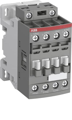
Ordering
1 piece
85364900
Popular Downloads
Dimensions
45 mm
77 mm
86 mm
0.31 kg
Technical
4
0
4P
IEC/EN 60947-1, IEC/EN 60947-5-1, UL 60335-2-40 LZGH2 A2L, UL 60947-5-1, CSA C22.2 No. 60335-2-40 LZGH2 A2L, CSA C22.2 No. 60947-5-1, IEC 60077-1 (applicable parts), IEC 60077-2 (applicable parts), EN 50155 (applicable parts), TR CU 001/2011, IEC 61373, For compliance confirmation on applicable parts based on your application and combination, please consult your ABB sales representatives.
Auxiliary Circuit 690 V
Auxiliary Circuit 50 / 60 Hz
Control Circuit 50 / 60 Hz
Main Circuit 50 / 60 Hz
Auxiliary Circuit 50 / 60 Hz
Control Circuit 50 / 60 Hz
Main Circuit 50 / 60 Hz
acc. to IEC 60947-5-1, Θ = 40 °C 16 A
(500 V) 2 A
(690 V) 2 A
(24 / 127 V) 6 A
(220 / 240 V) 4 A
(400 / 440 V) 3 A
(500 V) 2 A
(690 V) 2 A
(24 / 127 V) 6 A
(220 / 240 V) 4 A
(400 / 440 V) 3 A
(24 V) 6 A / 144 W
(48 V) 2.8 A / 134 W
(72 V) 1 A / 72 W
(110 V) 0.55 A / 60 W
(125 V) 0.55 A / 69 W
(220 V) 0.27 A / 60 W
(250 V) 0.27 A / 68 W
(400 V) 0.15 A / 60 W
(500 V) 0.13 A / 65 W
(600 V) 0.1 A / 60 W
(24 V) 6 A / 144 W
(48 V) 2.8 A / 134 W
(72 V) 1 A / 72 W
(110 V) 0.55 A / 60 W
(125 V) 0.55 A / 69 W
(220 V) 0.27 A / 60 W
(250 V) 0.27 A / 68 W
(400 V) 0.15 A / 60 W
(500 V) 0.13 A / 65 W
(600 V) 0.1 A / 60 W
for 0.1 s 140 A
for 1 s 100 A
for 0.1 s 140 A
for 1 s 100 A
acc. to IEC 60947-5-1 690 V
acc. to UL/CSA 600 V
acc. to IEC 60947-5-1 690 V
acc. to UL/CSA 600 V
6 kV
(AC-15) 1200 cycles per hour
(DC-13) 900 cycles per hour
(AC-15) 1200 cycles per hour
(DC-13) 900 cycles per hour
6000 cycles per hour
50 Hz 24 ... 60 V
60 Hz 24 ... 60 V
DC Operation 20 ... 60 V
50 Hz 24 ... 60 V
60 Hz 24 ... 60 V
DC Operation 20 ... 60 V
Between Coil De-energization and NC Contact Closing 13 ... 98 ms
Between Coil De-energization and NO Contact Opening 11 ... 95 ms
Between Coil Energization and NC Contact Opening 38 ... 90 ms
Between Coil Energization and NO Contact Closing 40 ... 95 ms
Between Coil De-energization and NC Contact Closing 13 ... 98 ms
Between Coil De-energization and NO Contact Opening 11 ... 95 ms
Between Coil Energization and NC Contact Opening 38 ... 90 ms
Between Coil Energization and NO Contact Closing 40 ... 95 ms
TH35-15 (35 x 15 mm Mounting Rail) acc. to IEC 60715
TH35-7.5 (35 x 7.5 mm Mounting Rail) acc. to IEC 60715
TH35-15 (35 x 15 mm Mounting Rail) acc. to IEC 60715
TH35-7.5 (35 x 7.5 mm Mounting Rail) acc. to IEC 60715
2 x M4 Screws Placed Diagonally
Flexible with Ferrule 1/2x 0.75 ... 2.5 mm²
Flexible with Insulated Ferrule 1x 0.75 ... 2.5 mm²
Flexible with Insulated Ferrule 2x 0.75 ... 1.5 mm²
Rigid Solid 1/2x 1 ... 2.5 mm²
Rigid Stranded 1/2x 1 ... 2.5 mm²
Flexible with Ferrule 1/2x 0.75 ... 2.5 mm²
Flexible with Insulated Ferrule 1x 0.75 ... 2.5 mm²
Flexible with Insulated Ferrule 2x 0.75 ... 1.5 mm²
Rigid Solid 1/2x 1 ... 2.5 mm²
Rigid Stranded 1/2x 1 ... 2.5 mm²
Flexible with Ferrule 1/2x 0.75 ... 2.5 mm²
Flexible with Insulated Ferrule 1x 0.75 ... 2.5 mm²
Flexible with Insulated Ferrule 2x 0.75 ... 1.5 mm²
Rigid Solid 1/2x 1 ... 2.5 mm²
Rigid Stranded 1/2x 1 ... 2.5 mm²
Flexible with Ferrule 1/2x 0.75 ... 2.5 mm²
Flexible with Insulated Ferrule 1x 0.75 ... 2.5 mm²
Flexible with Insulated Ferrule 2x 0.75 ... 1.5 mm²
Rigid Solid 1/2x 1 ... 2.5 mm²
Rigid Stranded 1/2x 1 ... 2.5 mm²
Control Circuit 10 mm
acc. to IEC 60529, IEC 60947-1, EN 60529 Auxiliary Terminals IP20
acc. to IEC 60529, IEC 60947-1, EN 60529 Coil Terminals IP20
acc. to IEC 60529, IEC 60947-1, EN 60529 Auxiliary Terminals IP20
acc. to IEC 60529, IEC 60947-1, EN 60529 Coil Terminals IP20
Auxiliary Circuit 1.2 N·m
Control Circuit 1.2 N·m
Auxiliary Circuit 1.2 N·m
Control Circuit 1.2 N·m
Screw Terminals
Block Contactor Relay
Technical UL/CSA
Rigid Solid 1/2x 18-14 AWG
Rigid Stranded 1/2x 18-14 AWG
Rigid Solid 1/2x 18-14 AWG
Rigid Stranded 1/2x 18-14 AWG
Auxiliary Circuit 11 in·lb
Control Circuit 11 in·lb
Auxiliary Circuit 11 in·lb
Control Circuit 11 in·lb
Environmental
Close to Contactor for Storage -60 ... +80 °C
Near Contactor for Operation in Free Air -40 ... 70 °C
Close to Contactor for Storage -60 ... +80 °C
Near Contactor for Operation in Free Air -40 ... 70 °C
Category B according to IEC 60947-1 Annex Q
Without Derating 3000 m
3
Material Compliance
Following EU Directive 2011/65/EU and Amendment 2015/863 July 22, 2019
Business To Business
5. Small Equipment (No External Dimension More Than 50 cm)
ABB EcoSolutions
Recycled Cardboard - 86 %
Recycled Metal - 28 %
Certificates and Declarations
Container Information
box 1 piece
87 mm
79 mm
47 mm
0.31 kg
3471523105416
box 27 piece
250 mm
300 mm
315 mm
16.74 kg
External Classifications and Standards
K
EC000196 - Contactor relay
EC000196 - Contactor relay
EC000196 - Contactor relay
V11.0 : 27371001
39121529
4763 >> Power contactor, DC switching
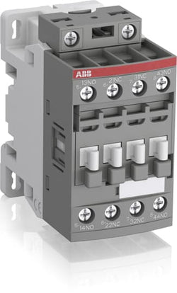
Ordering
1 piece
85364900
Popular Downloads
Dimensions
45 mm
77 mm
86 mm
0.27 kg
Technical
2
2
4P
IEC/EN 60947-1, IEC/EN 60947-5-1, UL 60335-2-40 LZGH2 A2L, UL 508, CSA C22.2 No. 60335-2-40 LZGH2 A2L, CSA C22.2 No. 14-13
Auxiliary Circuit 690 V
Auxiliary Circuit 50 / 60 Hz
Control Circuit 50 / 60 Hz
Auxiliary Circuit 50 / 60 Hz
Control Circuit 50 / 60 Hz
acc. to IEC 60947-5-1, Θ = 40 °C 16 A
(500 V) 2 A
(690 V) 2 A
(24 / 127 V) 6 A
(220 / 240 V) 4 A
(400 / 440 V) 3 A
(500 V) 2 A
(690 V) 2 A
(24 / 127 V) 6 A
(220 / 240 V) 4 A
(400 / 440 V) 3 A
(24 V) 6 A / 144 W
(48 V) 2.8 A / 134 W
(72 V) 1 A / 72 W
(110 V) 0.55 A / 60 W
(125 V) 0.55 A / 69 W
(220 V) 0.27 A / 60 W
(250 V) 0.27 A / 68 W
(400 V) 0.15 A / 60 W
(500 V) 0.13 A / 65 W
(600 V) 0.1 A / 60 W
(24 V) 6 A / 144 W
(48 V) 2.8 A / 134 W
(72 V) 1 A / 72 W
(110 V) 0.55 A / 60 W
(125 V) 0.55 A / 69 W
(220 V) 0.27 A / 60 W
(250 V) 0.27 A / 68 W
(400 V) 0.15 A / 60 W
(500 V) 0.13 A / 65 W
(600 V) 0.1 A / 60 W
for 0.1 s 140 A
for 1 s 100 A
for 0.1 s 140 A
for 1 s 100 A
acc. to IEC 60947-5-1 690 V
acc. to UL/CSA 600 V
acc. to IEC 60947-5-1 690 V
acc. to UL/CSA 600 V
6 kV
(AC-15) 1200 cycles per hour
(DC-13) 900 cycles per hour
(AC-15) 1200 cycles per hour
(DC-13) 900 cycles per hour
6000 cycles per hour
50 Hz 24 ... 60 V
60 Hz 24 ... 60 V
DC Operation 20 ... 60 V
50 Hz 24 ... 60 V
60 Hz 24 ... 60 V
DC Operation 20 ... 60 V
Between Coil De-energization and NC Contact Closing 13 ... 98 ms
Between Coil De-energization and NO Contact Opening 11 ... 95 ms
Between Coil Energization and NC Contact Opening 38 ... 90 ms
Between Coil Energization and NO Contact Closing 40 ... 95 ms
Between Coil De-energization and NC Contact Closing 13 ... 98 ms
Between Coil De-energization and NO Contact Opening 11 ... 95 ms
Between Coil Energization and NC Contact Opening 38 ... 90 ms
Between Coil Energization and NO Contact Closing 40 ... 95 ms
TH35-15 (35 x 15 mm Mounting Rail) acc. to IEC 60715
TH35-7.5 (35 x 7.5 mm Mounting Rail) acc. to IEC 60715
TH35-15 (35 x 15 mm Mounting Rail) acc. to IEC 60715
TH35-7.5 (35 x 7.5 mm Mounting Rail) acc. to IEC 60715
2 x M4 Screws Placed Diagonally
Flexible with Ferrule 1/2x 0.75 ... 2.5 mm²
Flexible with Insulated Ferrule 1x 0.75 ... 2.5 mm²
Flexible with Insulated Ferrule 2x 0.75 ... 1.5 mm²
Rigid Solid 1/2x 1 ... 2.5 mm²
Rigid Stranded 1/2x 1 ... 2.5 mm²
Flexible with Ferrule 1/2x 0.75 ... 2.5 mm²
Flexible with Insulated Ferrule 1x 0.75 ... 2.5 mm²
Flexible with Insulated Ferrule 2x 0.75 ... 1.5 mm²
Rigid Solid 1/2x 1 ... 2.5 mm²
Rigid Stranded 1/2x 1 ... 2.5 mm²
Flexible with Ferrule 1/2x 0.75 ... 2.5 mm²
Flexible with Insulated Ferrule 1x 0.75 ... 2.5 mm²
Flexible with Insulated Ferrule 2x 0.75 ... 1.5 mm²
Rigid Solid 1/2x 1 ... 2.5 mm²
Rigid Stranded 1/2x 1 ... 2.5 mm²
Flexible with Ferrule 1/2x 0.75 ... 2.5 mm²
Flexible with Insulated Ferrule 1x 0.75 ... 2.5 mm²
Flexible with Insulated Ferrule 2x 0.75 ... 1.5 mm²
Rigid Solid 1/2x 1 ... 2.5 mm²
Rigid Stranded 1/2x 1 ... 2.5 mm²
Auxiliary Circuit 10 mm
Control Circuit 10 mm
Auxiliary Circuit 10 mm
Control Circuit 10 mm
acc. to IEC 60529, IEC 60947-1, EN 60529 Auxiliary Terminals IP20
acc. to IEC 60529, IEC 60947-1, EN 60529 Coil Terminals IP20
acc. to IEC 60529, IEC 60947-1, EN 60529 Auxiliary Terminals IP20
acc. to IEC 60529, IEC 60947-1, EN 60529 Coil Terminals IP20
Auxiliary Circuit 1.2 N·m
Control Circuit 1.2 N·m
Auxiliary Circuit 1.2 N·m
Control Circuit 1.2 N·m
Screw Terminals
Block Contactor Relay
Technical UL/CSA
Rigid Solid 1/2x 18-14 AWG
Rigid Stranded 1/2x 18-14 AWG
Rigid Solid 1/2x 18-14 AWG
Rigid Stranded 1/2x 18-14 AWG
Auxiliary Circuit 11 in·lb
Control Circuit 11 in·lb
Auxiliary Circuit 11 in·lb
Control Circuit 11 in·lb
Environmental
Close to Contactor for Storage -60 ... +80 °C
Near Contactor for Operation in Free Air -40 ... 70 °C
Close to Contactor for Storage -60 ... +80 °C
Near Contactor for Operation in Free Air -40 ... 70 °C
Category B according to IEC 60947-1 Annex Q
Without Derating 3000 m
Closed, Shock Direction: B1 25 g
Open, Shock Direction: B1 5 g
Shock Direction: A 30 g
Shock Direction: B2 15 g
Shock Direction: C1 25 g
Shock Direction: C2 25 g
Closed, Shock Direction: B1 25 g
Open, Shock Direction: B1 5 g
Shock Direction: A 30 g
Shock Direction: B2 15 g
Shock Direction: C1 25 g
Shock Direction: C2 25 g
4g Closed Position & 2g Open position 5 ... 300 Hz
3
Material Compliance
Following EU Directive 2011/65/EU and Amendment 2015/863 July 22, 2019
3a7ec92f-2b59-4ce5-b08c-9a03d3c36d08 China
2ffee727-9423-4522-a5dc-5dd2e652996c Croatia
2ace32b3-e5c0-4f0f-bcd0-9e9b69856f75 Denmark
fa7ca2bf-2d20-4649-bc60-69c2768ae348 Sweden
6b134012-e324-488a-ad14-cdd573bd37bb Bulgaria
8f20f14c-5fb2-4666-855c-d23d163d326b Germany
d453f2c4-edb1-4d0f-bd25-846404a01957 Germany
751dec63-6235-42cb-a716-b24a7dc773f9 France
f12fe3a6-3a4a-4c5f-a3a9-84368c3af96f Poland
93971f11-c2c9-4ed6-8e3b-d4c76de45e18 Sweden
8dae6d97-8c74-4e52-9d9f-322f457b3b17 Germany
2ab6f7e8-088b-4a46-befa-2336e5ac63da Germany
50ce64e4-62ca-429e-be94-5403801d120b Spain
f55f1b39-0e66-49e0-80ef-a24977fcbdc8 Belgium
4a60baed-a224-4f36-8a87-28f049c5f338 Belgium
2a18fc35-5b38-4386-92b7-4448e33bd072 Portugal
fe309fc0-cad7-4e1d-bc34-f567e796daa5 France
2f3bec9a-60ea-46c4-8f56-771d3a065e51 Germany
ce2af395-0548-4622-b15f-607e3bb47270 Poland
b61de48c-1aa8-41e2-bf74-31b1478132f0 Czech Republic
f69a4ee0-314b-44c1-a9e9-0ae9b25346e6 Poland
1c7a215f-1b80-4e82-bfd8-b06367e446f3 Netherlands
473856fc-2170-4e82-9fa1-df8ebfb870af Estonia
0ede1b8f-42ec-460e-8e53-19be184edade Norway
4015edf7-1d14-4af1-b883-abc4fff42d8b Hungary
e7a0c3bb-5f09-4c4d-805a-0fe1c4896270 Hungary
837bcbfc-19d9-47a2-8090-dbd74b5b19bc Finland
3ebc7aed-5457-498f-95a8-5570cbbcf48c Greece
2ffee727-9423-4522-a5dc-5dd2e652996c Croatia
2ace32b3-e5c0-4f0f-bcd0-9e9b69856f75 Denmark
fa7ca2bf-2d20-4649-bc60-69c2768ae348 Sweden
6b134012-e324-488a-ad14-cdd573bd37bb Bulgaria
8f20f14c-5fb2-4666-855c-d23d163d326b Germany
d453f2c4-edb1-4d0f-bd25-846404a01957 Germany
751dec63-6235-42cb-a716-b24a7dc773f9 France
f12fe3a6-3a4a-4c5f-a3a9-84368c3af96f Poland
93971f11-c2c9-4ed6-8e3b-d4c76de45e18 Sweden
8dae6d97-8c74-4e52-9d9f-322f457b3b17 Germany
Business To Business
5. Small Equipment (No External Dimension More Than 50 cm)
ABB EcoSolutions
Recycled Cardboard - 86 %
Recycled Metal - 28 %
Certificates and Declarations
Container Information
box 1 piece
87 mm
79 mm
47 mm
0.27 kg
3471523100114
box 27 piece
250 mm
300 mm
315 mm
14.58 kg
External Classifications and Standards
K
EC000196 - Contactor relay
EC000196 - Contactor relay
EC000196 - Contactor relay
V11.0 : 27371001
39121529
4763 >> Power contactor, DC switching
3705813
3211470

Ordering
1 piece
85364900
Popular Downloads
Dimensions
45 mm
77 mm
86 mm
0.27 kg
Technical
3
1
4P
IEC/EN 60947-1, IEC/EN 60947-5-1, UL 60335-2-40 LZGH2 A2L, UL 508, CSA C22.2 No. 60335-2-40 LZGH2 A2L, CSA C22.2 No. 14-13
Auxiliary Circuit 690 V
Auxiliary Circuit 50 / 60 Hz
Control Circuit 50 / 60 Hz
Auxiliary Circuit 50 / 60 Hz
Control Circuit 50 / 60 Hz
acc. to IEC 60947-5-1, Θ = 40 °C 16 A
(500 V) 2 A
(690 V) 2 A
(24 / 127 V) 6 A
(220 / 240 V) 4 A
(400 / 440 V) 3 A
(500 V) 2 A
(690 V) 2 A
(24 / 127 V) 6 A
(220 / 240 V) 4 A
(400 / 440 V) 3 A
(24 V) 6 A / 144 W
(48 V) 2.8 A / 134 W
(72 V) 1 A / 72 W
(110 V) 0.55 A / 60 W
(125 V) 0.55 A / 69 W
(220 V) 0.27 A / 60 W
(250 V) 0.27 A / 68 W
(400 V) 0.15 A / 60 W
(500 V) 0.13 A / 65 W
(600 V) 0.1 A / 60 W
(24 V) 6 A / 144 W
(48 V) 2.8 A / 134 W
(72 V) 1 A / 72 W
(110 V) 0.55 A / 60 W
(125 V) 0.55 A / 69 W
(220 V) 0.27 A / 60 W
(250 V) 0.27 A / 68 W
(400 V) 0.15 A / 60 W
(500 V) 0.13 A / 65 W
(600 V) 0.1 A / 60 W
for 0.1 s 140 A
for 1 s 100 A
for 0.1 s 140 A
for 1 s 100 A
acc. to IEC 60947-5-1 690 V
acc. to UL/CSA 600 V
acc. to IEC 60947-5-1 690 V
acc. to UL/CSA 600 V
6 kV
(AC-15) 1200 cycles per hour
(DC-13) 900 cycles per hour
(AC-15) 1200 cycles per hour
(DC-13) 900 cycles per hour
6000 cycles per hour
50 Hz 24 ... 60 V
60 Hz 24 ... 60 V
DC Operation 20 ... 60 V
50 Hz 24 ... 60 V
60 Hz 24 ... 60 V
DC Operation 20 ... 60 V
Between Coil De-energization and NC Contact Closing 13 ... 98 ms
Between Coil De-energization and NO Contact Opening 11 ... 95 ms
Between Coil Energization and NC Contact Opening 38 ... 90 ms
Between Coil Energization and NO Contact Closing 40 ... 95 ms
Between Coil De-energization and NC Contact Closing 13 ... 98 ms
Between Coil De-energization and NO Contact Opening 11 ... 95 ms
Between Coil Energization and NC Contact Opening 38 ... 90 ms
Between Coil Energization and NO Contact Closing 40 ... 95 ms
TH35-15 (35 x 15 mm Mounting Rail) acc. to IEC 60715
TH35-7.5 (35 x 7.5 mm Mounting Rail) acc. to IEC 60715
TH35-15 (35 x 15 mm Mounting Rail) acc. to IEC 60715
TH35-7.5 (35 x 7.5 mm Mounting Rail) acc. to IEC 60715
2 x M4 Screws Placed Diagonally
Flexible with Ferrule 1/2x 0.75 ... 2.5 mm²
Flexible with Insulated Ferrule 1x 0.75 ... 2.5 mm²
Flexible with Insulated Ferrule 2x 0.75 ... 1.5 mm²
Rigid Solid 1/2x 1 ... 2.5 mm²
Rigid Stranded 1/2x 1 ... 2.5 mm²
Flexible with Ferrule 1/2x 0.75 ... 2.5 mm²
Flexible with Insulated Ferrule 1x 0.75 ... 2.5 mm²
Flexible with Insulated Ferrule 2x 0.75 ... 1.5 mm²
Rigid Solid 1/2x 1 ... 2.5 mm²
Rigid Stranded 1/2x 1 ... 2.5 mm²
Flexible with Ferrule 1/2x 0.75 ... 2.5 mm²
Flexible with Insulated Ferrule 1x 0.75 ... 2.5 mm²
Flexible with Insulated Ferrule 2x 0.75 ... 1.5 mm²
Rigid Solid 1/2x 1 ... 2.5 mm²
Rigid Stranded 1/2x 1 ... 2.5 mm²
Flexible with Ferrule 1/2x 0.75 ... 2.5 mm²
Flexible with Insulated Ferrule 1x 0.75 ... 2.5 mm²
Flexible with Insulated Ferrule 2x 0.75 ... 1.5 mm²
Rigid Solid 1/2x 1 ... 2.5 mm²
Rigid Stranded 1/2x 1 ... 2.5 mm²
Auxiliary Circuit 10 mm
Control Circuit 10 mm
Auxiliary Circuit 10 mm
Control Circuit 10 mm
acc. to IEC 60529, IEC 60947-1, EN 60529 Auxiliary Terminals IP20
acc. to IEC 60529, IEC 60947-1, EN 60529 Coil Terminals IP20
acc. to IEC 60529, IEC 60947-1, EN 60529 Auxiliary Terminals IP20
acc. to IEC 60529, IEC 60947-1, EN 60529 Coil Terminals IP20
Auxiliary Circuit 1.2 N·m
Control Circuit 1.2 N·m
Auxiliary Circuit 1.2 N·m
Control Circuit 1.2 N·m
Screw Terminals
Block Contactor Relay
Technical UL/CSA
Rigid Solid 1/2x 18-14 AWG
Rigid Stranded 1/2x 18-14 AWG
Rigid Solid 1/2x 18-14 AWG
Rigid Stranded 1/2x 18-14 AWG
Auxiliary Circuit 11 in·lb
Control Circuit 11 in·lb
Auxiliary Circuit 11 in·lb
Control Circuit 11 in·lb
Environmental
Close to Contactor for Storage -60 ... +80 °C
Near Contactor for Operation in Free Air -40 ... 70 °C
Close to Contactor for Storage -60 ... +80 °C
Near Contactor for Operation in Free Air -40 ... 70 °C
Category B according to IEC 60947-1 Annex Q
Without Derating 3000 m
Closed, Shock Direction: B1 25 g
Open, Shock Direction: B1 5 g
Shock Direction: A 30 g
Shock Direction: B2 15 g
Shock Direction: C1 25 g
Shock Direction: C2 25 g
Closed, Shock Direction: B1 25 g
Open, Shock Direction: B1 5 g
Shock Direction: A 30 g
Shock Direction: B2 15 g
Shock Direction: C1 25 g
Shock Direction: C2 25 g
4g Closed Position & 2g Open position 5 ... 300 Hz
3
Material Compliance
Following EU Directive 2011/65/EU and Amendment 2015/863 July 22, 2019
9eec38a3-9a2f-4533-aec7-8d767bb26afb China
87de14ba-6fc3-4689-8870-a0c7fb4c3e07 Croatia
35d3cdc1-0abc-484f-bc62-416a7476489a Czech Republic
21b7a0b6-231e-4e1f-97b0-6be8f7331f83 Germany
e508cb08-d215-41a2-be8c-00768893d74f Bulgaria
33918f1d-0a3e-43f3-b510-15560fb0556f Sweden
714cfb70-9f69-4cf2-859a-6ff54767c0d5 Germany
9383611c-707d-4099-b85d-43ebb71f6fea Denmark
3977102c-ee02-4544-b022-c7c129431e51 Germany
40a64cd0-962b-47af-a36d-076ffa6459f0 Poland
77d5993c-23a4-429b-b541-15daf8bdbf88 France
dfba97cc-6848-41df-b59a-fbb8cd6dcea9 Sweden
e75b5760-925a-4b41-b555-feefff1d6a55 Germany
5c304043-6cc3-4449-8382-68a8509c031d Portugal
32e603c8-a963-42c4-a40f-c84afa315d0a Belgium
a73b071a-d983-4639-bc11-02f1b3fa000c Hungary
6ae49f82-e721-470f-9ca2-f7e2448efcc5 Norway
1d6e9ab9-76ac-47e2-b293-e12de717c481 Estonia
487a8590-e8f1-451f-ad87-bd9f0b11ecb8 Hungary
5b58bcb4-1ef6-40f2-a662-8da56e47d4cb Finland
00a381a1-271c-4515-90f5-30ee8ae943b7 Spain
eee265b1-5d89-449b-bcd6-dae1fabfa3f7 Greece
d96b8547-06c9-4cbb-8704-c43479e17d3a Belgium
0ce9e120-0f85-4154-8d25-0e0cc5cfafe2 Netherlands
70889373-7818-41ce-85a0-16cceafd576f Poland
fadcb295-0c9a-4c76-812c-e13730f6b94f Poland
148f3a64-300b-4877-9398-7cffbaaf6462 Germany
92ff169e-41c0-45fe-96cf-0f5d678fa870 France
87de14ba-6fc3-4689-8870-a0c7fb4c3e07 Croatia
35d3cdc1-0abc-484f-bc62-416a7476489a Czech Republic
21b7a0b6-231e-4e1f-97b0-6be8f7331f83 Germany
e508cb08-d215-41a2-be8c-00768893d74f Bulgaria
33918f1d-0a3e-43f3-b510-15560fb0556f Sweden
714cfb70-9f69-4cf2-859a-6ff54767c0d5 Germany
9383611c-707d-4099-b85d-43ebb71f6fea Denmark
3977102c-ee02-4544-b022-c7c129431e51 Germany
40a64cd0-962b-47af-a36d-076ffa6459f0 Poland
77d5993c-23a4-429b-b541-15daf8bdbf88 France
Business To Business
5. Small Equipment (No External Dimension More Than 50 cm)
ABB EcoSolutions
Recycled Cardboard - 86 %
Recycled Metal - 28 %
Certificates and Declarations
Container Information
box 1 piece
87 mm
79 mm
47 mm
0.27 kg
3471523100213
box 27 piece
250 mm
300 mm
315 mm
14.58 kg
External Classifications and Standards
K
EC000196 - Contactor relay
EC000196 - Contactor relay
EC000196 - Contactor relay
V11.0 : 27371001
39121529
4763 >> Power contactor, DC switching
3705814
3211471
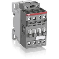
Ordering
1 piece
85364900
Popular Downloads
Dimensions
45 mm
77 mm
86 mm
0.27 kg
Technical
4
0
4P
IEC/EN 60947-1, IEC/EN 60947-5-1, UL 60335-2-40 LZGH2 A2L, UL 508, CSA C22.2 No. 60335-2-40 LZGH2 A2L, CSA C22.2 No. 14-13
Auxiliary Circuit 690 V
Auxiliary Circuit 50 / 60 Hz
Control Circuit 50 / 60 Hz
Auxiliary Circuit 50 / 60 Hz
Control Circuit 50 / 60 Hz
acc. to IEC 60947-5-1, Θ = 40 °C 16 A
(500 V) 2 A
(690 V) 2 A
(24 / 127 V) 6 A
(220 / 240 V) 4 A
(400 / 440 V) 3 A
(500 V) 2 A
(690 V) 2 A
(24 / 127 V) 6 A
(220 / 240 V) 4 A
(400 / 440 V) 3 A
(24 V) 6 A / 144 W
(48 V) 2.8 A / 134 W
(72 V) 1 A / 72 W
(110 V) 0.55 A / 60 W
(125 V) 0.55 A / 69 W
(220 V) 0.27 A / 60 W
(250 V) 0.27 A / 68 W
(400 V) 0.15 A / 60 W
(500 V) 0.13 A / 65 W
(600 V) 0.1 A / 60 W
(24 V) 6 A / 144 W
(48 V) 2.8 A / 134 W
(72 V) 1 A / 72 W
(110 V) 0.55 A / 60 W
(125 V) 0.55 A / 69 W
(220 V) 0.27 A / 60 W
(250 V) 0.27 A / 68 W
(400 V) 0.15 A / 60 W
(500 V) 0.13 A / 65 W
(600 V) 0.1 A / 60 W
for 0.1 s 140 A
for 1 s 100 A
for 0.1 s 140 A
for 1 s 100 A
acc. to IEC 60947-5-1 690 V
acc. to UL/CSA 600 V
acc. to IEC 60947-5-1 690 V
acc. to UL/CSA 600 V
6 kV
(AC-15) 1200 cycles per hour
(DC-13) 900 cycles per hour
(AC-15) 1200 cycles per hour
(DC-13) 900 cycles per hour
6000 cycles per hour
50 Hz 24 ... 60 V
60 Hz 24 ... 60 V
DC Operation 20 ... 60 V
50 Hz 24 ... 60 V
60 Hz 24 ... 60 V
DC Operation 20 ... 60 V
Between Coil De-energization and NC Contact Closing 13 ... 98 ms
Between Coil De-energization and NO Contact Opening 11 ... 95 ms
Between Coil Energization and NC Contact Opening 38 ... 90 ms
Between Coil Energization and NO Contact Closing 40 ... 95 ms
Between Coil De-energization and NC Contact Closing 13 ... 98 ms
Between Coil De-energization and NO Contact Opening 11 ... 95 ms
Between Coil Energization and NC Contact Opening 38 ... 90 ms
Between Coil Energization and NO Contact Closing 40 ... 95 ms
TH35-15 (35 x 15 mm Mounting Rail) acc. to IEC 60715
TH35-7.5 (35 x 7.5 mm Mounting Rail) acc. to IEC 60715
TH35-15 (35 x 15 mm Mounting Rail) acc. to IEC 60715
TH35-7.5 (35 x 7.5 mm Mounting Rail) acc. to IEC 60715
2 x M4 Screws Placed Diagonally
Flexible with Ferrule 1/2x 0.75 ... 2.5 mm²
Flexible with Insulated Ferrule 1x 0.75 ... 2.5 mm²
Flexible with Insulated Ferrule 2x 0.75 ... 1.5 mm²
Rigid Solid 1/2x 1 ... 2.5 mm²
Rigid Stranded 1/2x 1 ... 2.5 mm²
Flexible with Ferrule 1/2x 0.75 ... 2.5 mm²
Flexible with Insulated Ferrule 1x 0.75 ... 2.5 mm²
Flexible with Insulated Ferrule 2x 0.75 ... 1.5 mm²
Rigid Solid 1/2x 1 ... 2.5 mm²
Rigid Stranded 1/2x 1 ... 2.5 mm²
Flexible with Ferrule 1/2x 0.75 ... 2.5 mm²
Flexible with Insulated Ferrule 1x 0.75 ... 2.5 mm²
Flexible with Insulated Ferrule 2x 0.75 ... 1.5 mm²
Rigid Solid 1/2x 1 ... 2.5 mm²
Rigid Stranded 1/2x 1 ... 2.5 mm²
Flexible with Ferrule 1/2x 0.75 ... 2.5 mm²
Flexible with Insulated Ferrule 1x 0.75 ... 2.5 mm²
Flexible with Insulated Ferrule 2x 0.75 ... 1.5 mm²
Rigid Solid 1/2x 1 ... 2.5 mm²
Rigid Stranded 1/2x 1 ... 2.5 mm²
Auxiliary Circuit 10 mm
Control Circuit 10 mm
Auxiliary Circuit 10 mm
Control Circuit 10 mm
acc. to IEC 60529, IEC 60947-1, EN 60529 Auxiliary Terminals IP20
acc. to IEC 60529, IEC 60947-1, EN 60529 Coil Terminals IP20
acc. to IEC 60529, IEC 60947-1, EN 60529 Auxiliary Terminals IP20
acc. to IEC 60529, IEC 60947-1, EN 60529 Coil Terminals IP20
Auxiliary Circuit 1.2 N·m
Control Circuit 1.2 N·m
Auxiliary Circuit 1.2 N·m
Control Circuit 1.2 N·m
Screw Terminals
Block Contactor Relay
Technical UL/CSA
Rigid Solid 1/2x 18-14 AWG
Rigid Stranded 1/2x 18-14 AWG
Rigid Solid 1/2x 18-14 AWG
Rigid Stranded 1/2x 18-14 AWG
Auxiliary Circuit 11 in·lb
Control Circuit 11 in·lb
Auxiliary Circuit 11 in·lb
Control Circuit 11 in·lb
Environmental
Close to Contactor for Storage -60 ... +80 °C
Near Contactor for Operation in Free Air -40 ... 70 °C
Close to Contactor for Storage -60 ... +80 °C
Near Contactor for Operation in Free Air -40 ... 70 °C
Category B according to IEC 60947-1 Annex Q
Without Derating 3000 m
Closed, Shock Direction: B1 25 g
Open, Shock Direction: B1 5 g
Shock Direction: A 30 g
Shock Direction: B2 15 g
Shock Direction: C1 25 g
Shock Direction: C2 25 g
Closed, Shock Direction: B1 25 g
Open, Shock Direction: B1 5 g
Shock Direction: A 30 g
Shock Direction: B2 15 g
Shock Direction: C1 25 g
Shock Direction: C2 25 g
4g Closed Position & 2g Open position 5 ... 300 Hz
3
Material Compliance
Following EU Directive 2011/65/EU and Amendment 2015/863 July 22, 2019
1a2faa22-43e2-463a-8b2f-81189663d8f8 China
cd4298e0-b2a6-4b82-a9c2-ea4b593ca801 Croatia
da6f077a-837d-4300-af7a-9a59194950fe Czech Republic
356cfa40-0141-4484-8924-b39b16bebdcf France
9fad57f9-5a56-48e3-979a-98b073d84091 Germany
9705c9e3-c33e-43aa-830b-b10ced0c1702 Poland
6c9dd0c3-2187-4bc0-aa9a-03593fb8b78a Germany
3e22c15d-c287-4e18-8dc7-56216b7ee40e Sweden
1eb7dbd1-163d-4739-8b57-0b4972aa61f9 Portugal
8991069e-13df-4a17-9507-ebf0adad87e1 Bulgaria
7bbe17de-4c62-4c6a-8551-16e2e5afee81 Denmark
018f6551-55a0-49ce-98d6-de48078dc34c France
b89234cd-1b4a-4cde-a0fb-f2ba2f0280a1 Germany
b7c3be1c-0c2a-43e1-8a74-8f63c33fa39b Sweden
b36a6e26-d731-4a16-905b-d37e468a686b Greece
ba131cce-5c7d-4461-a395-2afd3879f6b6 Spain
27b42269-c0b6-4261-a0dd-7cfe73876c0b Belgium
fb5ff361-e373-4f0f-b25f-0f6ba1a2123e Germany
aede2d2a-2e1f-452b-8d35-42b7648b1107 Belgium
6b81305b-fe00-439e-b256-c6efc3140426 Germany
8984f589-38e6-47a0-82bf-30f957cf474d Norway
17d1bf22-eeb1-4ad1-af05-f7dae6872c4d Hungary
e7ae0424-d5c8-4607-943a-c037bc602c48 Netherlands
47c1ef89-4f98-4b9f-9fe1-0f2a6f2baaab Poland
682ab83f-5aa8-474c-8770-90fc65ffdeee Poland
4d4ad4e3-add2-496d-8be7-ac01a07fbd01 Hungary
9a33b1df-a2eb-4f87-8534-b446bbf8deba Estonia
9501d551-d39a-4446-8618-dd37a2c8f951 Finland
cd4298e0-b2a6-4b82-a9c2-ea4b593ca801 Croatia
da6f077a-837d-4300-af7a-9a59194950fe Czech Republic
356cfa40-0141-4484-8924-b39b16bebdcf France
9fad57f9-5a56-48e3-979a-98b073d84091 Germany
9705c9e3-c33e-43aa-830b-b10ced0c1702 Poland
6c9dd0c3-2187-4bc0-aa9a-03593fb8b78a Germany
3e22c15d-c287-4e18-8dc7-56216b7ee40e Sweden
1eb7dbd1-163d-4739-8b57-0b4972aa61f9 Portugal
8991069e-13df-4a17-9507-ebf0adad87e1 Bulgaria
7bbe17de-4c62-4c6a-8551-16e2e5afee81 Denmark
Business To Business
5. Small Equipment (No External Dimension More Than 50 cm)
ABB EcoSolutions
Recycled Cardboard - 86 %
Recycled Metal - 28 %
Certificates and Declarations
Container Information
box 1 piece
87 mm
79 mm
47 mm
0.27 kg
3471523100015
box 27 piece
250 mm
300 mm
315 mm
14.58 kg
External Classifications and Standards
K
EC000196 - Contactor relay
EC000196 - Contactor relay
EC000196 - Contactor relay
V11.0 : 27371001
39121529
4763 >> Power contactor, DC switching
3705815
3211472

Ordering
1 piece
85364900
Popular Downloads
Dimensions
45 mm
77 mm
86 mm
0.27 kg
Technical
2
2
4P
IEC/EN 60947-1, IEC/EN 60947-5-1, UL 60335-2-40 LZGH2 A2L, UL 508, CSA C22.2 No. 60335-2-40 LZGH2 A2L, CSA C22.2 No. 14-13
Auxiliary Circuit 690 V
Auxiliary Circuit 50 / 60 Hz
Control Circuit 50 / 60 Hz
Auxiliary Circuit 50 / 60 Hz
Control Circuit 50 / 60 Hz
acc. to IEC 60947-5-1, Θ = 40 °C 16 A
(500 V) 2 A
(690 V) 2 A
(24 / 127 V) 6 A
(220 / 240 V) 4 A
(400 / 440 V) 3 A
(500 V) 2 A
(690 V) 2 A
(24 / 127 V) 6 A
(220 / 240 V) 4 A
(400 / 440 V) 3 A
(24 V) 6 A / 144 W
(48 V) 2.8 A / 134 W
(72 V) 1 A / 72 W
(110 V) 0.55 A / 60 W
(125 V) 0.55 A / 69 W
(220 V) 0.27 A / 60 W
(250 V) 0.27 A / 68 W
(400 V) 0.15 A / 60 W
(500 V) 0.13 A / 65 W
(600 V) 0.1 A / 60 W
(24 V) 6 A / 144 W
(48 V) 2.8 A / 134 W
(72 V) 1 A / 72 W
(110 V) 0.55 A / 60 W
(125 V) 0.55 A / 69 W
(220 V) 0.27 A / 60 W
(250 V) 0.27 A / 68 W
(400 V) 0.15 A / 60 W
(500 V) 0.13 A / 65 W
(600 V) 0.1 A / 60 W
for 0.1 s 140 A
for 1 s 100 A
for 0.1 s 140 A
for 1 s 100 A
acc. to IEC 60947-5-1 690 V
acc. to UL/CSA 600 V
acc. to IEC 60947-5-1 690 V
acc. to UL/CSA 600 V
6 kV
(AC-15) 1200 cycles per hour
(DC-13) 900 cycles per hour
(AC-15) 1200 cycles per hour
(DC-13) 900 cycles per hour
6000 cycles per hour
50 Hz 48 ... 130 V
60 Hz 48 ... 130 V
DC Operation 48 ... 130 V
50 Hz 48 ... 130 V
60 Hz 48 ... 130 V
DC Operation 48 ... 130 V
Between Coil De-energization and NC Contact Closing 13 ... 98 ms
Between Coil De-energization and NO Contact Opening 11 ... 95 ms
Between Coil Energization and NC Contact Opening 38 ... 90 ms
Between Coil Energization and NO Contact Closing 40 ... 95 ms
Between Coil De-energization and NC Contact Closing 13 ... 98 ms
Between Coil De-energization and NO Contact Opening 11 ... 95 ms
Between Coil Energization and NC Contact Opening 38 ... 90 ms
Between Coil Energization and NO Contact Closing 40 ... 95 ms
TH35-15 (35 x 15 mm Mounting Rail) acc. to IEC 60715
TH35-7.5 (35 x 7.5 mm Mounting Rail) acc. to IEC 60715
TH35-15 (35 x 15 mm Mounting Rail) acc. to IEC 60715
TH35-7.5 (35 x 7.5 mm Mounting Rail) acc. to IEC 60715
2 x M4 Screws Placed Diagonally
Flexible with Ferrule 1/2x 0.75 ... 2.5 mm²
Flexible with Insulated Ferrule 1x 0.75 ... 2.5 mm²
Flexible with Insulated Ferrule 2x 0.75 ... 1.5 mm²
Rigid Solid 1/2x 1 ... 2.5 mm²
Rigid Stranded 1/2x 1 ... 2.5 mm²
Flexible with Ferrule 1/2x 0.75 ... 2.5 mm²
Flexible with Insulated Ferrule 1x 0.75 ... 2.5 mm²
Flexible with Insulated Ferrule 2x 0.75 ... 1.5 mm²
Rigid Solid 1/2x 1 ... 2.5 mm²
Rigid Stranded 1/2x 1 ... 2.5 mm²
Flexible with Ferrule 1/2x 0.75 ... 2.5 mm²
Flexible with Insulated Ferrule 1x 0.75 ... 2.5 mm²
Flexible with Insulated Ferrule 2x 0.75 ... 1.5 mm²
Rigid Solid 1/2x 1 ... 2.5 mm²
Rigid Stranded 1/2x 1 ... 2.5 mm²
Flexible with Ferrule 1/2x 0.75 ... 2.5 mm²
Flexible with Insulated Ferrule 1x 0.75 ... 2.5 mm²
Flexible with Insulated Ferrule 2x 0.75 ... 1.5 mm²
Rigid Solid 1/2x 1 ... 2.5 mm²
Rigid Stranded 1/2x 1 ... 2.5 mm²
Auxiliary Circuit 10 mm
Control Circuit 10 mm
Auxiliary Circuit 10 mm
Control Circuit 10 mm
acc. to IEC 60529, IEC 60947-1, EN 60529 Auxiliary Terminals IP20
acc. to IEC 60529, IEC 60947-1, EN 60529 Coil Terminals IP20
acc. to IEC 60529, IEC 60947-1, EN 60529 Auxiliary Terminals IP20
acc. to IEC 60529, IEC 60947-1, EN 60529 Coil Terminals IP20
Auxiliary Circuit 1.2 N·m
Control Circuit 1.2 N·m
Auxiliary Circuit 1.2 N·m
Control Circuit 1.2 N·m
Screw Terminals
Block Contactor Relay
Technical UL/CSA
Rigid Solid 1/2x 18-14 AWG
Rigid Stranded 1/2x 18-14 AWG
Rigid Solid 1/2x 18-14 AWG
Rigid Stranded 1/2x 18-14 AWG
Auxiliary Circuit 11 in·lb
Control Circuit 11 in·lb
Auxiliary Circuit 11 in·lb
Control Circuit 11 in·lb
Environmental
Close to Contactor for Storage -60 ... +80 °C
Near Contactor for Operation in Free Air -40 ... 70 °C
Close to Contactor for Storage -60 ... +80 °C
Near Contactor for Operation in Free Air -40 ... 70 °C
Category B according to IEC 60947-1 Annex Q
Without Derating 3000 m
Closed, Shock Direction: B1 25 g
Open, Shock Direction: B1 5 g
Shock Direction: A 30 g
Shock Direction: B2 15 g
Shock Direction: C1 25 g
Shock Direction: C2 25 g
Closed, Shock Direction: B1 25 g
Open, Shock Direction: B1 5 g
Shock Direction: A 30 g
Shock Direction: B2 15 g
Shock Direction: C1 25 g
Shock Direction: C2 25 g
4g Closed Position & 2g Open position 5 ... 300 Hz
3
Material Compliance
Following EU Directive 2011/65/EU and Amendment 2015/863 July 22, 2019
9c6250d8-fcb2-49d9-96ef-e2b90c4082b5 China
ca50bc8c-9aa7-4d44-af4d-c33e790aa1fb Spain
ae3272d1-d41e-422e-826a-606791148c91 Norway
4560e2c4-41a2-47d8-b930-11eca29d3047 Poland
90061623-5dce-4bab-a146-77c596185a56 Czech Republic
7deaf105-5205-4b8d-9955-2d4ed3e5f90f Estonia
28e059b7-3311-4b90-b5f3-c6efc95592b0 Greece
52e0a1bd-b878-4341-b38e-3be56f7ee65e Poland
6b1cdc7e-135c-44be-81bc-bf58cbedede6 Netherlands
8d8b873f-4b10-473f-97d2-32e9de87344d Hungary
7053e1a2-17ee-49f0-befc-2e5d2edbd870 Croatia
8caec7cc-68e8-4d70-a1f9-227fbf52cd3c Belgium
45b1d3a9-9404-4795-ae39-470955d4f893 Finland
befc78dd-3a0d-4b77-afc4-da54dfc891b5 Denmark
0a247b74-d2a5-4ca8-81ff-431b6ca01187 Germany
870f88ea-8ef1-497a-9ac1-4221f78d30bf Germany
98d05b2d-c71d-45fd-b98d-913a8c72a3f6 Germany
e051b4f2-8a93-4f5a-b614-563ccfdfec6b Sweden
e95f7259-d98b-45ea-ba99-3fbf7f25ac0e France
e4f1fdc4-2daf-4c4d-a3fb-12a06676eb01 Belgium
ef91dda2-118a-490b-9454-67667286ab19 Hungary
d10f9534-29ef-4f1d-bf56-5111455f4d89 Germany
c47e6196-1e07-49be-8e5c-b1db855d2c8c Poland
0cb447f9-8ea2-4a6a-a3c4-9123c3f8de77 France
80ce89b6-b714-40de-9b40-5e80e5a8bf60 Sweden
5642285f-eec0-4d7e-bf87-cf1473402b52 Bulgaria
2bbc6e2a-7321-4249-9998-106d88a6d85e Portugal
fb383559-a7a8-4813-ae48-f237aa3f282e Germany
ca50bc8c-9aa7-4d44-af4d-c33e790aa1fb Spain
ae3272d1-d41e-422e-826a-606791148c91 Norway
4560e2c4-41a2-47d8-b930-11eca29d3047 Poland
90061623-5dce-4bab-a146-77c596185a56 Czech Republic
7deaf105-5205-4b8d-9955-2d4ed3e5f90f Estonia
28e059b7-3311-4b90-b5f3-c6efc95592b0 Greece
52e0a1bd-b878-4341-b38e-3be56f7ee65e Poland
6b1cdc7e-135c-44be-81bc-bf58cbedede6 Netherlands
8d8b873f-4b10-473f-97d2-32e9de87344d Hungary
7053e1a2-17ee-49f0-befc-2e5d2edbd870 Croatia
Business To Business
5. Small Equipment (No External Dimension More Than 50 cm)
ABB EcoSolutions
Recycled Cardboard - 86 %
Recycled Metal - 28 %
Certificates and Declarations
Container Information
box 1 piece
87 mm
79 mm
47 mm
0.27 kg
3471523100121
box 27 piece
250 mm
300 mm
315 mm
14.58 kg
External Classifications and Standards
K
EC000196 - Contactor relay
EC000196 - Contactor relay
EC000196 - Contactor relay
V11.0 : 27371001
39121529
4763 >> Power contactor, DC switching
3706400
3211447

Ordering
1 piece
85364900
Popular Downloads
Dimensions
45 mm
77 mm
86 mm
0.27 kg
Technical
3
1
4P
IEC/EN 60947-1, IEC/EN 60947-5-1, UL 60335-2-40 LZGH2 A2L, UL 508, CSA C22.2 No. 60335-2-40 LZGH2 A2L, CSA C22.2 No. 14-13
Auxiliary Circuit 690 V
Auxiliary Circuit 50 / 60 Hz
Control Circuit 50 / 60 Hz
Auxiliary Circuit 50 / 60 Hz
Control Circuit 50 / 60 Hz
acc. to IEC 60947-5-1, Θ = 40 °C 16 A
(500 V) 2 A
(690 V) 2 A
(24 / 127 V) 6 A
(220 / 240 V) 4 A
(400 / 440 V) 3 A
(500 V) 2 A
(690 V) 2 A
(24 / 127 V) 6 A
(220 / 240 V) 4 A
(400 / 440 V) 3 A
(24 V) 6 A / 144 W
(48 V) 2.8 A / 134 W
(72 V) 1 A / 72 W
(110 V) 0.55 A / 60 W
(125 V) 0.55 A / 69 W
(220 V) 0.27 A / 60 W
(250 V) 0.27 A / 68 W
(400 V) 0.15 A / 60 W
(500 V) 0.13 A / 65 W
(600 V) 0.1 A / 60 W
(24 V) 6 A / 144 W
(48 V) 2.8 A / 134 W
(72 V) 1 A / 72 W
(110 V) 0.55 A / 60 W
(125 V) 0.55 A / 69 W
(220 V) 0.27 A / 60 W
(250 V) 0.27 A / 68 W
(400 V) 0.15 A / 60 W
(500 V) 0.13 A / 65 W
(600 V) 0.1 A / 60 W
for 0.1 s 140 A
for 1 s 100 A
for 0.1 s 140 A
for 1 s 100 A
acc. to IEC 60947-5-1 690 V
acc. to UL/CSA 600 V
acc. to IEC 60947-5-1 690 V
acc. to UL/CSA 600 V
6 kV
(AC-15) 1200 cycles per hour
(DC-13) 900 cycles per hour
(AC-15) 1200 cycles per hour
(DC-13) 900 cycles per hour
6000 cycles per hour
50 Hz 48 ... 130 V
60 Hz 48 ... 130 V
DC Operation 48 ... 130 V
50 Hz 48 ... 130 V
60 Hz 48 ... 130 V
DC Operation 48 ... 130 V
Between Coil De-energization and NC Contact Closing 13 ... 98 ms
Between Coil De-energization and NO Contact Opening 11 ... 95 ms
Between Coil Energization and NC Contact Opening 38 ... 90 ms
Between Coil Energization and NO Contact Closing 40 ... 95 ms
Between Coil De-energization and NC Contact Closing 13 ... 98 ms
Between Coil De-energization and NO Contact Opening 11 ... 95 ms
Between Coil Energization and NC Contact Opening 38 ... 90 ms
Between Coil Energization and NO Contact Closing 40 ... 95 ms
TH35-15 (35 x 15 mm Mounting Rail) acc. to IEC 60715
TH35-7.5 (35 x 7.5 mm Mounting Rail) acc. to IEC 60715
TH35-15 (35 x 15 mm Mounting Rail) acc. to IEC 60715
TH35-7.5 (35 x 7.5 mm Mounting Rail) acc. to IEC 60715
2 x M4 Screws Placed Diagonally
Flexible with Ferrule 1/2x 0.75 ... 2.5 mm²
Flexible with Insulated Ferrule 1x 0.75 ... 2.5 mm²
Flexible with Insulated Ferrule 2x 0.75 ... 1.5 mm²
Rigid Solid 1/2x 1 ... 2.5 mm²
Rigid Stranded 1/2x 1 ... 2.5 mm²
Flexible with Ferrule 1/2x 0.75 ... 2.5 mm²
Flexible with Insulated Ferrule 1x 0.75 ... 2.5 mm²
Flexible with Insulated Ferrule 2x 0.75 ... 1.5 mm²
Rigid Solid 1/2x 1 ... 2.5 mm²
Rigid Stranded 1/2x 1 ... 2.5 mm²
Flexible with Ferrule 1/2x 0.75 ... 2.5 mm²
Flexible with Insulated Ferrule 1x 0.75 ... 2.5 mm²
Flexible with Insulated Ferrule 2x 0.75 ... 1.5 mm²
Rigid Solid 1/2x 1 ... 2.5 mm²
Rigid Stranded 1/2x 1 ... 2.5 mm²
Flexible with Ferrule 1/2x 0.75 ... 2.5 mm²
Flexible with Insulated Ferrule 1x 0.75 ... 2.5 mm²
Flexible with Insulated Ferrule 2x 0.75 ... 1.5 mm²
Rigid Solid 1/2x 1 ... 2.5 mm²
Rigid Stranded 1/2x 1 ... 2.5 mm²
Auxiliary Circuit 10 mm
Control Circuit 10 mm
Auxiliary Circuit 10 mm
Control Circuit 10 mm
acc. to IEC 60529, IEC 60947-1, EN 60529 Auxiliary Terminals IP20
acc. to IEC 60529, IEC 60947-1, EN 60529 Coil Terminals IP20
acc. to IEC 60529, IEC 60947-1, EN 60529 Auxiliary Terminals IP20
acc. to IEC 60529, IEC 60947-1, EN 60529 Coil Terminals IP20
Auxiliary Circuit 1.2 N·m
Control Circuit 1.2 N·m
Auxiliary Circuit 1.2 N·m
Control Circuit 1.2 N·m
Screw Terminals
Block Contactor Relay
Technical UL/CSA
Rigid Solid 1/2x 18-14 AWG
Rigid Stranded 1/2x 18-14 AWG
Rigid Solid 1/2x 18-14 AWG
Rigid Stranded 1/2x 18-14 AWG
Auxiliary Circuit 11 in·lb
Control Circuit 11 in·lb
Auxiliary Circuit 11 in·lb
Control Circuit 11 in·lb
Environmental
Close to Contactor for Storage -60 ... +80 °C
Near Contactor for Operation in Free Air -40 ... 70 °C
Close to Contactor for Storage -60 ... +80 °C
Near Contactor for Operation in Free Air -40 ... 70 °C
Category B according to IEC 60947-1 Annex Q
Without Derating 3000 m
Closed, Shock Direction: B1 25 g
Open, Shock Direction: B1 5 g
Shock Direction: A 30 g
Shock Direction: B2 15 g
Shock Direction: C1 25 g
Shock Direction: C2 25 g
Closed, Shock Direction: B1 25 g
Open, Shock Direction: B1 5 g
Shock Direction: A 30 g
Shock Direction: B2 15 g
Shock Direction: C1 25 g
Shock Direction: C2 25 g
4g Closed Position & 2g Open position 5 ... 300 Hz
3
Material Compliance
Following EU Directive 2011/65/EU and Amendment 2015/863 July 22, 2019
39fe6513-a151-4c74-8373-95317a877365 China
7bbfcec9-fbb9-4480-a98c-c72a8f66f53f France
bf63ee6e-4854-414e-aa29-3361b1b0a042 Germany
d29736a4-e49b-4671-945f-81897be834cb Portugal
b8325cc7-629a-48c9-bcd6-8dfd81df79a4 Sweden
d01bca23-0d3e-4993-ab68-2f61d96e1081 Bulgaria
b1723259-1218-4458-9fc4-022fddd5764c Poland
67bc1ae3-686c-4164-923c-43117212072f Sweden
e1842006-eefa-454d-99bf-39c7cf11ded5 Germany
8e4c61a6-7a24-47ef-aa4b-4f387f4c2eaa Hungary
f0eaa4da-9dbc-4e00-aa4a-006c61774bc6 Belgium
fc95e4c8-27c6-4d83-b7ca-433748bf7a86 France
72af2f0e-c037-45f0-80ca-b75377b23866 Greece
82b0ae30-adb1-42b8-a9fd-f99428e5a66a Estonia
01c3322b-3076-4d67-b83d-4391d3c1f54e Netherlands
c8abad75-e6bb-4513-a3e8-ecf302cc3032 Hungary
0fb2015f-8c7d-4498-ac09-392aed91c760 Poland
c6073e7e-ddc2-4ce0-9fe2-42bc5afc0a90 Belgium
51f355d0-e034-46c8-9588-32a32eedad71 Norway
71b860ee-fa94-4386-9663-eabe18846575 Finland
d8355767-3289-41fd-b134-778dfcd57b37 Czech Republic
348b1e2b-fc3e-4730-a1ac-0401f8bcdcb0 Poland
87b3c4b5-1a24-43b7-b0a0-db21fb7668e0 Germany
a405a508-7e84-4ba6-8335-ee255cad9407 Spain
4d15e9a6-5ddd-49c9-8084-6ea31a92d198 Croatia
f0546562-f7e6-4b6a-bb60-b8a130675b59 Germany
e5d78903-3463-497b-a595-c5a06ba7f4be Denmark
b6a81eac-0a52-4c81-895a-5115cb344753 Germany
7bbfcec9-fbb9-4480-a98c-c72a8f66f53f France
bf63ee6e-4854-414e-aa29-3361b1b0a042 Germany
d29736a4-e49b-4671-945f-81897be834cb Portugal
b8325cc7-629a-48c9-bcd6-8dfd81df79a4 Sweden
d01bca23-0d3e-4993-ab68-2f61d96e1081 Bulgaria
b1723259-1218-4458-9fc4-022fddd5764c Poland
67bc1ae3-686c-4164-923c-43117212072f Sweden
e1842006-eefa-454d-99bf-39c7cf11ded5 Germany
8e4c61a6-7a24-47ef-aa4b-4f387f4c2eaa Hungary
f0eaa4da-9dbc-4e00-aa4a-006c61774bc6 Belgium
Business To Business
5. Small Equipment (No External Dimension More Than 50 cm)
ABB EcoSolutions
Recycled Cardboard - 86 %
Recycled Metal - 28 %
Certificates and Declarations
Container Information
box 1 piece
87 mm
79 mm
47 mm
0.27 kg
3471523100220
box 27 piece
250 mm
300 mm
315 mm
14.58 kg
External Classifications and Standards
K
EC000196 - Contactor relay
EC000196 - Contactor relay
EC000196 - Contactor relay
V11.0 : 27371001
39121529
4763 >> Power contactor, DC switching
3706407
3211451
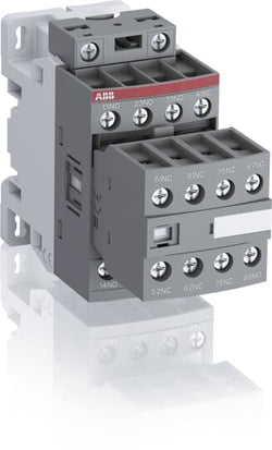
Ordering
1 piece
85364900
Popular Downloads
Dimensions
45 mm
110.5 mm
86 mm
0.32 kg
Technical
4
4
8P
IEC/EN 60947-1, IEC/EN 60947-5-1, UL 60335-2-40 LZGH2 A2L, UL 508, CSA C22.2 No. 60335-2-40 LZGH2 A2L, CSA C22.2 No. 14-13
Auxiliary Circuit 690 V
Auxiliary Circuit 50 / 60 Hz
Control Circuit 50 / 60 Hz
Auxiliary Circuit 50 / 60 Hz
Control Circuit 50 / 60 Hz
acc. to IEC 60947-5-1, Θ = 40 °C 16 A
(500 V) 2 A
(690 V) 2 A
(24 / 127 V) 6 A
(220 / 240 V) 4 A
(400 / 440 V) 3 A
(500 V) 2 A
(690 V) 2 A
(24 / 127 V) 6 A
(220 / 240 V) 4 A
(400 / 440 V) 3 A
(24 V) 6 A / 144 W
(48 V) 2.8 A / 134 W
(72 V) 1 A / 72 W
(110 V) 0.55 A / 60 W
(125 V) 0.55 A / 69 W
(220 V) 0.27 A / 60 W
(250 V) 0.27 A / 68 W
(400 V) 0.15 A / 60 W
(500 V) 0.13 A / 65 W
(600 V) 0.1 A / 60 W
(24 V) 6 A / 144 W
(48 V) 2.8 A / 134 W
(72 V) 1 A / 72 W
(110 V) 0.55 A / 60 W
(125 V) 0.55 A / 69 W
(220 V) 0.27 A / 60 W
(250 V) 0.27 A / 68 W
(400 V) 0.15 A / 60 W
(500 V) 0.13 A / 65 W
(600 V) 0.1 A / 60 W
for 0.1 s 140 A
for 1 s 100 A
for 0.1 s 140 A
for 1 s 100 A
acc. to IEC 60947-5-1 690 V
acc. to UL/CSA 600 V
acc. to IEC 60947-5-1 690 V
acc. to UL/CSA 600 V
6 kV
(AC-15) 1200 cycles per hour
(DC-13) 900 cycles per hour
(AC-15) 1200 cycles per hour
(DC-13) 900 cycles per hour
6000 cycles per hour
50 Hz 48 ... 130 V
60 Hz 48 ... 130 V
DC Operation 48 ... 130 V
50 Hz 48 ... 130 V
60 Hz 48 ... 130 V
DC Operation 48 ... 130 V
Between Coil De-energization and NC Contact Closing 13 ... 98 ms
Between Coil De-energization and NO Contact Opening 11 ... 95 ms
Between Coil Energization and NC Contact Opening 38 ... 90 ms
Between Coil Energization and NO Contact Closing 40 ... 95 ms
Between Coil De-energization and NC Contact Closing 13 ... 98 ms
Between Coil De-energization and NO Contact Opening 11 ... 95 ms
Between Coil Energization and NC Contact Opening 38 ... 90 ms
Between Coil Energization and NO Contact Closing 40 ... 95 ms
TH35-15 (35 x 15 mm Mounting Rail) acc. to IEC 60715
TH35-7.5 (35 x 7.5 mm Mounting Rail) acc. to IEC 60715
TH35-15 (35 x 15 mm Mounting Rail) acc. to IEC 60715
TH35-7.5 (35 x 7.5 mm Mounting Rail) acc. to IEC 60715
2 x M4 Screws Placed Diagonally
Flexible with Ferrule 1/2x 0.75 ... 2.5 mm²
Flexible with Insulated Ferrule 1x 0.75 ... 2.5 mm²
Flexible with Insulated Ferrule 2x 0.75 ... 1.5 mm²
Rigid Solid 1/2x 1 ... 2.5 mm²
Rigid Stranded 1/2x 1 ... 2.5 mm²
Flexible with Ferrule 1/2x 0.75 ... 2.5 mm²
Flexible with Insulated Ferrule 1x 0.75 ... 2.5 mm²
Flexible with Insulated Ferrule 2x 0.75 ... 1.5 mm²
Rigid Solid 1/2x 1 ... 2.5 mm²
Rigid Stranded 1/2x 1 ... 2.5 mm²
Flexible with Ferrule 1/2x 0.75 ... 2.5 mm²
Flexible with Insulated Ferrule 1x 0.75 ... 2.5 mm²
Flexible with Insulated Ferrule 2x 0.75 ... 1.5 mm²
Rigid Solid 1/2x 1 ... 2.5 mm²
Rigid Stranded 1/2x 1 ... 2.5 mm²
Flexible with Ferrule 1/2x 0.75 ... 2.5 mm²
Flexible with Insulated Ferrule 1x 0.75 ... 2.5 mm²
Flexible with Insulated Ferrule 2x 0.75 ... 1.5 mm²
Rigid Solid 1/2x 1 ... 2.5 mm²
Rigid Stranded 1/2x 1 ... 2.5 mm²
Auxiliary Circuit 10 mm
Control Circuit 10 mm
Auxiliary Circuit 10 mm
Control Circuit 10 mm
acc. to IEC 60529, IEC 60947-1, EN 60529 Auxiliary Terminals IP20
acc. to IEC 60529, IEC 60947-1, EN 60529 Coil Terminals IP20
acc. to IEC 60529, IEC 60947-1, EN 60529 Auxiliary Terminals IP20
acc. to IEC 60529, IEC 60947-1, EN 60529 Coil Terminals IP20
Auxiliary Circuit 1.2 N·m
Control Circuit 1.2 N·m
Auxiliary Circuit 1.2 N·m
Control Circuit 1.2 N·m
Screw Terminals
Block Contactor Relay
Technical UL/CSA
Rigid Solid 1/2x 18-14 AWG
Rigid Stranded 1/2x 18-14 AWG
Rigid Solid 1/2x 18-14 AWG
Rigid Stranded 1/2x 18-14 AWG
Auxiliary Circuit 11 in·lb
Control Circuit 11 in·lb
Auxiliary Circuit 11 in·lb
Control Circuit 11 in·lb
Environmental
Close to Contactor for Storage -60 ... +80 °C
Near Contactor for Operation in Free Air -40 ... 70 °C
Close to Contactor for Storage -60 ... +80 °C
Near Contactor for Operation in Free Air -40 ... 70 °C
Category B according to IEC 60947-1 Annex Q
Without Derating 3000 m
Closed, Shock Direction: B1 25 g
Closed, Shock Direction: B2 15 g
Open, Shock Direction: B1 5 g
Shock Direction: A 30 g
Shock Direction: B2 15 g
Shock Direction: C1 25 g
Closed, Shock Direction: B1 25 g
Closed, Shock Direction: B2 15 g
Open, Shock Direction: B1 5 g
Shock Direction: A 30 g
Shock Direction: B2 15 g
Shock Direction: C1 25 g
4g Closed Position & 2g Open position 5 ... 300 Hz
3
Material Compliance
Following EU Directive 2011/65/EU and Amendment 2015/863 July 22, 2019
Business To Business
5. Small Equipment (No External Dimension More Than 50 cm)
ABB EcoSolutions
Recycled Cardboard - 86 %
Recycled Metal - 28 %
Certificates and Declarations
Container Information
box 1 piece
87 mm
113 mm
47 mm
0.34 kg
3471523107625
box 18 piece
250 mm
300 mm
315 mm
11.52 kg
External Classifications and Standards
K
EC000196 - Contactor relay
EC000196 - Contactor relay
EC000196 - Contactor relay
V11.0 : 27371001
39121500

Ordering
1 piece
85364900
Popular Downloads
Dimensions
45 mm
77 mm
86 mm
0.27 kg
Technical
4
0
4P
IEC/EN 60947-1, IEC/EN 60947-5-1, UL 60335-2-40 LZGH2 A2L, UL 508, CSA C22.2 No. 60335-2-40 LZGH2 A2L, CSA C22.2 No. 14-13
Auxiliary Circuit 690 V
Auxiliary Circuit 50 / 60 Hz
Control Circuit 50 / 60 Hz
Auxiliary Circuit 50 / 60 Hz
Control Circuit 50 / 60 Hz
acc. to IEC 60947-5-1, Θ = 40 °C 16 A
(500 V) 2 A
(690 V) 2 A
(24 / 127 V) 6 A
(220 / 240 V) 4 A
(400 / 440 V) 3 A
(500 V) 2 A
(690 V) 2 A
(24 / 127 V) 6 A
(220 / 240 V) 4 A
(400 / 440 V) 3 A
(24 V) 6 A / 144 W
(48 V) 2.8 A / 134 W
(72 V) 1 A / 72 W
(110 V) 0.55 A / 60 W
(125 V) 0.55 A / 69 W
(220 V) 0.27 A / 60 W
(250 V) 0.27 A / 68 W
(400 V) 0.15 A / 60 W
(500 V) 0.13 A / 65 W
(600 V) 0.1 A / 60 W
(24 V) 6 A / 144 W
(48 V) 2.8 A / 134 W
(72 V) 1 A / 72 W
(110 V) 0.55 A / 60 W
(125 V) 0.55 A / 69 W
(220 V) 0.27 A / 60 W
(250 V) 0.27 A / 68 W
(400 V) 0.15 A / 60 W
(500 V) 0.13 A / 65 W
(600 V) 0.1 A / 60 W
for 0.1 s 140 A
for 1 s 100 A
for 0.1 s 140 A
for 1 s 100 A
acc. to IEC 60947-5-1 690 V
acc. to UL/CSA 600 V
acc. to IEC 60947-5-1 690 V
acc. to UL/CSA 600 V
6 kV
(AC-15) 1200 cycles per hour
(DC-13) 900 cycles per hour
(AC-15) 1200 cycles per hour
(DC-13) 900 cycles per hour
6000 cycles per hour
50 Hz 48 ... 130 V
60 Hz 48 ... 130 V
DC Operation 48 ... 130 V
50 Hz 48 ... 130 V
60 Hz 48 ... 130 V
DC Operation 48 ... 130 V
Between Coil De-energization and NC Contact Closing 13 ... 98 ms
Between Coil De-energization and NO Contact Opening 11 ... 95 ms
Between Coil Energization and NC Contact Opening 38 ... 90 ms
Between Coil Energization and NO Contact Closing 40 ... 95 ms
Between Coil De-energization and NC Contact Closing 13 ... 98 ms
Between Coil De-energization and NO Contact Opening 11 ... 95 ms
Between Coil Energization and NC Contact Opening 38 ... 90 ms
Between Coil Energization and NO Contact Closing 40 ... 95 ms
TH35-15 (35 x 15 mm Mounting Rail) acc. to IEC 60715
TH35-7.5 (35 x 7.5 mm Mounting Rail) acc. to IEC 60715
TH35-15 (35 x 15 mm Mounting Rail) acc. to IEC 60715
TH35-7.5 (35 x 7.5 mm Mounting Rail) acc. to IEC 60715
2 x M4 Screws Placed Diagonally
Flexible with Ferrule 1/2x 0.75 ... 2.5 mm²
Flexible with Insulated Ferrule 1x 0.75 ... 2.5 mm²
Flexible with Insulated Ferrule 2x 0.75 ... 1.5 mm²
Rigid Solid 1/2x 1 ... 2.5 mm²
Rigid Stranded 1/2x 1 ... 2.5 mm²
Flexible with Ferrule 1/2x 0.75 ... 2.5 mm²
Flexible with Insulated Ferrule 1x 0.75 ... 2.5 mm²
Flexible with Insulated Ferrule 2x 0.75 ... 1.5 mm²
Rigid Solid 1/2x 1 ... 2.5 mm²
Rigid Stranded 1/2x 1 ... 2.5 mm²
Flexible with Ferrule 1/2x 0.75 ... 2.5 mm²
Flexible with Insulated Ferrule 1x 0.75 ... 2.5 mm²
Flexible with Insulated Ferrule 2x 0.75 ... 1.5 mm²
Rigid Solid 1/2x 1 ... 2.5 mm²
Rigid Stranded 1/2x 1 ... 2.5 mm²
Flexible with Ferrule 1/2x 0.75 ... 2.5 mm²
Flexible with Insulated Ferrule 1x 0.75 ... 2.5 mm²
Flexible with Insulated Ferrule 2x 0.75 ... 1.5 mm²
Rigid Solid 1/2x 1 ... 2.5 mm²
Rigid Stranded 1/2x 1 ... 2.5 mm²
Auxiliary Circuit 10 mm
Control Circuit 10 mm
Auxiliary Circuit 10 mm
Control Circuit 10 mm
acc. to IEC 60529, IEC 60947-1, EN 60529 Auxiliary Terminals IP20
acc. to IEC 60529, IEC 60947-1, EN 60529 Coil Terminals IP20
acc. to IEC 60529, IEC 60947-1, EN 60529 Auxiliary Terminals IP20
acc. to IEC 60529, IEC 60947-1, EN 60529 Coil Terminals IP20
Auxiliary Circuit 1.2 N·m
Control Circuit 1.2 N·m
Auxiliary Circuit 1.2 N·m
Control Circuit 1.2 N·m
Screw Terminals
Block Contactor Relay
Technical UL/CSA
Rigid Solid 1/2x 18-14 AWG
Rigid Stranded 1/2x 18-14 AWG
Rigid Solid 1/2x 18-14 AWG
Rigid Stranded 1/2x 18-14 AWG
Auxiliary Circuit 11 in·lb
Control Circuit 11 in·lb
Auxiliary Circuit 11 in·lb
Control Circuit 11 in·lb
Environmental
Close to Contactor for Storage -60 ... +80 °C
Near Contactor for Operation in Free Air -40 ... 70 °C
Close to Contactor for Storage -60 ... +80 °C
Near Contactor for Operation in Free Air -40 ... 70 °C
Category B according to IEC 60947-1 Annex Q
Without Derating 3000 m
Closed, Shock Direction: B1 25 g
Open, Shock Direction: B1 5 g
Shock Direction: A 30 g
Shock Direction: B2 15 g
Shock Direction: C1 25 g
Shock Direction: C2 25 g
Closed, Shock Direction: B1 25 g
Open, Shock Direction: B1 5 g
Shock Direction: A 30 g
Shock Direction: B2 15 g
Shock Direction: C1 25 g
Shock Direction: C2 25 g
4g Closed Position & 2g Open position 5 ... 300 Hz
3
Material Compliance
Following EU Directive 2011/65/EU and Amendment 2015/863 July 22, 2019
43a387df-ed0c-4710-aec0-e0200811e715 China
78ae90e0-a7b0-4779-b380-b51dfc15cd21 Denmark
f2515c82-811f-4490-af66-e4564b335c35 Germany
9d18775b-9d0a-44e0-8b2b-cdc93a6e3029 Germany
cd39f5ac-ee0a-4c0a-a0c6-ea7347172e70 Croatia
6a7107da-d14b-48f2-a7b6-bdbeb28eebd9 Hungary
01e5c70c-7860-46d0-8014-9c5df8fc65db Belgium
e10344bb-accc-4343-a1cc-f0f3efca92fb Germany
59cbf182-11b5-4ad3-8610-0c60235678ae France
bf2b1466-0b83-48bf-ae5e-fb76d057b585 Sweden
087d19b6-7c3b-49ba-9e0e-0097426ec8af Sweden
e1e05689-6f16-429d-9690-3de300eb0915 Portugal
3bb48cc5-cc60-47da-bede-0df6e7009d5e Bulgaria
06715de8-cc17-4192-9fc8-d7fbc4b87f4b Poland
53820df1-30d7-45d2-8fea-1a9c402149be Germany
2619a5ed-0c4a-4925-9d44-8b913ca8de08 France
24601d19-a3cb-4603-b968-2ce45b55fd25 Estonia
1d7c30e0-e0ef-4982-9e31-b40cb936dd60 Greece
f972f849-0fc2-4427-b41c-b380f9877d27 Netherlands
3a8c97e2-7f03-407c-a0c0-badcceaddabc Poland
ae1f466c-c958-455c-9ba0-b350de019c3d Hungary
f29d08ba-77e8-433c-9253-f3d587c3ffe9 Spain
8b4aefa1-c3a6-47e2-b61e-b0280004de5e Norway
0ec1b628-aab6-4782-b583-406d81fa0470 Poland
d53ef64c-e4b9-42db-a03f-9d2408690ffc Germany
2161be85-8986-4226-b733-3218651f76a2 Czech Republic
c6269559-b0b9-4461-8e79-da14d3f4d5c7 Belgium
5748385b-9246-4a2a-ba3b-34945af4ec21 Finland
78ae90e0-a7b0-4779-b380-b51dfc15cd21 Denmark
f2515c82-811f-4490-af66-e4564b335c35 Germany
9d18775b-9d0a-44e0-8b2b-cdc93a6e3029 Germany
cd39f5ac-ee0a-4c0a-a0c6-ea7347172e70 Croatia
6a7107da-d14b-48f2-a7b6-bdbeb28eebd9 Hungary
01e5c70c-7860-46d0-8014-9c5df8fc65db Belgium
e10344bb-accc-4343-a1cc-f0f3efca92fb Germany
59cbf182-11b5-4ad3-8610-0c60235678ae France
bf2b1466-0b83-48bf-ae5e-fb76d057b585 Sweden
087d19b6-7c3b-49ba-9e0e-0097426ec8af Sweden
Business To Business
5. Small Equipment (No External Dimension More Than 50 cm)
ABB EcoSolutions
Recycled Cardboard - 86 %
Recycled Metal - 28 %
Certificates and Declarations
Container Information
box 1 piece
87 mm
79 mm
47 mm
0.27 kg
3471523100022
box 27 piece
250 mm
300 mm
315 mm
14.58 kg
External Classifications and Standards
K
EC000196 - Contactor relay
EC000196 - Contactor relay
EC000196 - Contactor relay
V11.0 : 27371001
39121529
4763 >> Power contactor, DC switching
3706414
3211455