
 1 year warranty


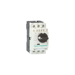
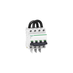
TeSys GV motor circuit breaker, 3 poles (3P), 80A/690V, for protection of 3-phase motors 22-37kW@400V. It provides thermal magnetic protection and additional motor protection functions, breaking capacity Icu 50kA@400V, start-stop control by rotary handle, connection for bars or cables with lugs. Thermal protection adjustable by dials with a setting current Ir in range 40-80A and a selectable tripping class 10 or 20, magnetic protection at 17 In. Additional protections have fixed pick-up and include short time delay protection Isd at 13 Ir, phase unbalance and loss protection, ground fault protection. It makes internal locations available for additional auxiliary contact blocks (OF, SD), and voltage trip units (MN, MX). Multi standards certified (IEC, UL, CSA, CCC, EAC, Marine, ATEX).
Main
| Characteristic | Value(s) |
|---|---|
| Range of Product | TeSys GV4 |
| Range | TeSys Deca |
| Device short name | GV4P |
| product name | TeSys GV4 |
| Product or Component Type | Motor circuit breaker |
| Device Application | Motor protection |
| Trip unit technology | Electronic Thermal-magnetic |
Complementary
| Characteristic | Value(s) |
|---|---|
| Poles description | 3P |
| Utilisation category | Category A IEC 60947-2 AC-3 IEC 60947-4-1 |
| Operating position | Any position |
| Motor power kW | 37 kW 400...415 V AC 50/60 Hz 45 kW 500 V AC 50/60 Hz 22 kW 400...415 V AC 50/60 Hz 30 kW 500 V AC 50/60 Hz 37 kW 660...690 V AC 50/60 Hz 45 kW 660...690 V AC 50/60 Hz 55 kW 660...690 V AC 50/60 Hz 30 kW 400...415 V AC 50/60 Hz 37 kW 500 V AC 50/60 Hz |
| Breaking capacity | 100 kA Icu 220...240 V AC 50/60 Hz IEC 60947-2 50 kA Icu 380...415 V AC 50/60 Hz IEC 60947-2 50 kA Icu 440 V AC 50/60 Hz IEC 60947-2 15 kA Icu 525 V AC 50/60 Hz IEC 60947-2 65 kA 208Y/120 V AC 50/60 Hz UL 60947 65 kA 240 V AC 50/60 Hz UL 60947 35 kA 480Y/277 V AC 50/60 Hz UL 60947 8 kA Icu 660...690 V AC 50/60 Hz IEC 60947-2 25 kA Icu 500 V AC 50/60 Hz IEC 60947-2 18 kA 600Y/347 V AC 50/60 Hz UL 60947 |
| Control Type | Rotary handle |
| Line Rated Current | 80 A |
| Magnetic tripping current | 1360 A |
| [Ue] rated operational voltage | 690 V AC 50/60 Hz IEC 60947-2 |
| [Ui] rated insulation voltage | 800 V AC 50/60 Hz IEC 60947-2 |
| [Ith] conventional free air thermal current | 115 A IEC 60947-4-1 |
| [Uimp] rated impulse withstand voltage | 8 kV IEC 60947-2 |
| Power dissipation per pole | 4.6 W |
| Mechanical durability | 40000 cycles |
| Electrical durability | 14000 cycles AC-3 440 V In/2 7000 cycles AC-3 440 V In |
| Maximum operating rate | 25 cyc/h |
| Rated duty | Continuous IEC 60947-4-1 |
| Connection pitch | 1.06 in (27 mm) without spreaders 1.4 in (35 mm) with spreaders |
| Connections - terminals | Lugs-ring terminals |
| Tightening torque | 79.7 lbf.in (9 N.m) 0.02â¦0.1 in² (16â¦95 mm²) 44.3 lbf.in (5 N.m) 0.002â¦0.02 in² (1.5â¦10 mm²) |
| Mechanical robustness | Vibrations +/- 1 mm 2...13.2 Hz IEC 60068-2-6 Vibrations 0.7 gn 13.2...100 Hz IEC 60068-2-6 Shocks 15 gn 11 ms IEC 60068-2-27 |
| Phase failure sensitivity | Yes IEC 60947-4-1 |
| Height | 6.1 in (155 mm) |
| Width | 3.2 in (81 mm) |
| Depth | 6.5 in (165 mm) |
| Product Weight | 3.5 lb(US) (1.6 kg) |
| color | Gray RAL 7016) |
| Suitability for isolation | Yes IEC 60947-1 |

PLC Direct is not an authorized distributor. We offer a broad range of in-stock products with minimal lead time.


Motor circuit breaker, TeSys GV2, 3P, 0.25-0.4 A, thermal magnetic, screw clamp terminals

TeSys GV motor circuit breaker, 3 poles (3P), 80A/690V, for protection of 3-phase motors 22-37kW@400V. It provides magnetic protection, breaking capacity Icu 100kA@400V, start-stop control by toggle, connection by Everlink BTR screw terminals. Magnetic protection adjustable by dial, setting range 6-14 In. It makes internal locations available for additional auxiliary contact blocks (OF, SD), and voltage trip units (MN, MX). To be used in association with a class 10 or 20 thermal overload relay to complete motor protection. Multi standards certified (IEC, CCC, EAC, Marine).
Main
| Characteristic | Value(s) |
|---|---|
| Range of product | TeSys GV4 |
| Range | TeSys Deca |
| Device short name | GV4L |
| product name | TeSys GV4 |
| Product or component type | Motor circuit breaker |
| Device application | Motor protection |
| Trip unit technology | Magnetic Electronic |
Complementary
| Characteristic | Value(s) |
|---|---|
| Poles description | 3P |
| Utilisation category | Category A conforming to IEC 60947-2 AC-3 conforming to IEC 60947-4-1 |
| Operating position | Any position |
| Motor power kW | 37 kW at 400...415 V AC 50/60 Hz 45 kW at 500 V AC 50/60 Hz 55 kW at 500 V AC 50/60 Hz 22 kW at 400...415 V AC 50/60 Hz 30 kW at 500 V AC 50/60 Hz 37 kW at 660...690 V AC 50/60 Hz 45 kW at 660...690 V AC 50/60 Hz 55 kW at 660...690 V AC 50/60 Hz 30 kW at 400...415 V AC 50/60 Hz 37 kW at 500 V AC 50/60 Hz |
| Breaking capacity | 120 kA Icu at 220...240 V AC 50/60 Hz conforming to IEC 60947-2 100 kA Icu at 380...415 V AC 50/60 Hz conforming to IEC 60947-2 70 kA Icu at 440 V AC 50/60 Hz conforming to IEC 60947-2 30 kA Icu at 500 V AC 50/60 Hz conforming to IEC 60947-2 18 kA Icu at 525 V AC 50/60 Hz conforming to IEC 60947-2 10 kA Icu at 660...690 V AC 50/60 Hz conforming to IEC 60947-2 |
| control type | Toggle |
| [In] rated current | 80 A |
| Magnetic tripping current | 480â¦1120 A |
| [Ue] rated operational voltage | 690 V AC 50/60 Hz conforming to IEC 60947-2 |
| [Ui] rated insulation voltage | 800 V AC 50/60 Hz conforming to IEC 60947-2 |
| [Ith] conventional free air thermal current | 115 A conforming to IEC 60947-4-1 |
| [Uimp] rated impulse withstand voltage | 8 kV conforming to IEC 60947-2 |
| Power dissipation per pole | 6.1 W |
| Mechanical durability | 40000 cycles |
| Electrical durability | 14000 cycles for AC-3 at 440 V In/2 7000 cycles for AC-3 at 440 V In |
| Maximum operating rate | 25 cyc/h |
| Rated duty | Continuous conforming to IEC 60947-4-1 |
| Connections - terminals | EverLink BTR screw connectors (top) 1 cable(s) 1.5â¦70 mm² - solid EverLink BTR screw connectors (top) 1 cable(s) 1.5â¦50 mm² - flexible EverLink BTR screw connectors (bottom) 1 cable(s) 2.5â¦95 mm² - solid EverLink BTR screw connectors (bottom) 1 cable(s) 2.5â¦70 mm² - flexible |
| Tightening torque | 9 N.m for cable 16â¦95 mm² 5 N.m for cable 1.5â¦10 mm² |
| Mechanical robustness | Vibrations: +/- 1 mm 2...13.2 Hz conforming to IEC 60068-2-6 Vibrations: 0.7 gn 13.2...100 Hz conforming to IEC 60068-2-6 Shocks: 15 gn 11 ms conforming to IEC 60068-2-27 |
| Height | 155 mm |
| Width | 81 mm |
| Depth | 116 mm |
| Product weight | 1.5 kg |
| Colour | Grey (RAL 7016) |
| Suitability for isolation | Yes conforming to IEC 60947-1 |
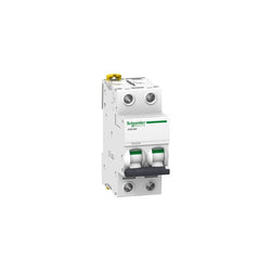
This Acti9 iC60L is a low voltage miniature circuit breaker (MCB). It is a 2P circuit breaker with 2 protected poles, 6.3A rated current and MA tripping curve. The rated short circuit breaking capacity goes up to 40kA at 220VAC to 240VAC conforming to EN/IEC 60947-2 standard. It complies with both industrial standard EN/IEC 60898-1 and residential standard EN/IEC 60947-2. This miniature circuit breaker protects circuit against short circuit and overload current. Its unique VisiTrip indicator reduces intervention time by showing the faulty circuit. Its VisiSafe green strip guarantees the physical opening of the contacts to allow downstream maintenance. Its fast closing mechanism independent of manual operation improves its service life. It has an electrical endurance going up to 10000 cycles and a mechanical endurance going up to 20000 cycles. The Ui rated insulation voltage is 500VAC. Its limitation class 3 (according to EN/IEC60898-1) improves downstream circuit protection cost. The product can be clipped on a DIN rail. Its width is 4 pitches of 9mm. Pollution degree is 3. Overvoltage category is IV. The product colour is white (RAL9003). The dimensions are (W) 36mm x (H) 85mm x (D) 78.5mm. The weight is 0.25kg. It has an IP20 degree of protection (as per IEC/EN 60529) on its terminals. The operating temperature is -35°C to 70°C. The storage temperature is -40°C to 85°C.
Main
| Characteristic | Value(s) |
|---|---|
| Device application | Motor |
| Range | Acti9 |
| product name | Acti9 iC60 |
| Product or component type | Miniature circuit-breaker |
| Device short name | iC60L |
| Poles description | 2P |
| Number of protected poles | 2 |
| [In] rated current | 6.3 A |
| Network type | AC |
| Trip unit technology | Magnetic |
| Curve code | MA |
| Breaking capacity | 15 kA Icu at 440 V AC 50/60 Hz conforming to EN/IEC 60947-2 20 kA Icu at 380...415 V AC 50/60 Hz conforming to EN/IEC 60947-2 40 kA Icu at 220...240 V AC 50/60 Hz conforming to EN/IEC 60947-2 |
| Utilisation category | Category A conforming to EN 60947-2 Category A conforming to IEC 60947-2 |
| Suitability for isolation | Yes conforming to EN 60947-2 Yes conforming to IEC 60947-2 |
| Standards | IEC 60947-2 EN 60947-2 |
Complementary
| Characteristic | Value(s) |
|---|---|
| Network frequency | 50/60 Hz |
| Magnetic tripping limit | 12 x In +/- 20 % |
| [Ics] rated service breaking capacity | 10 kA 50 % conforming to EN 60947-2 - 380...415 V AC 50/60 Hz 7.5 kA 50 % conforming to EN 60947-2 - 440 V AC 50/60 Hz 10 kA 50 % conforming to IEC 60947-2 - 380...415 V AC 50/60 Hz 7.5 kA 50 % conforming to IEC 60947-2 - 440 V AC 50/60 Hz 20 kA 50 % conforming to EN 60947-2 - 220...240 V AC 50/60 Hz 20 kA 50 % conforming to IEC 60947-2 - 220...240 V AC 50/60 Hz |
| Limitation class | 3 conforming to EN 60898-1 3 conforming to IEC 60898-1 |
| [Ui] rated insulation voltage | 500 V AC 50/60 Hz conforming to EN 60947-2 500 V AC 50/60 Hz conforming to IEC 60947-2 |
| [Uimp] rated impulse withstand voltage | 6 kV conforming to EN 60947-2 6 kV conforming to IEC 60947-2 |
| Contact position indicator | Yes |
| control type | Toggle |
| Local signalling | Trip indicator |
| Mounting mode | Fixed |
| Mounting support | DIN rail |
| Comb busbar and distribution block compatibility | Top or bottom: YES |
| 9 mm pitches | 4 |
| Height | 85 mm |
| Width | 36 mm |
| Depth | 78.5 mm |
| Product weight | 0.25 kg |
| Colour | White |
| Mechanical durability | 20000 cycles |
| Electrical durability | 10000 cycles |
| Connections - terminals | Single terminal (top or bottom) 1â¦25 mm² rigid Single terminal (top or bottom) 1â¦16 mm² flexible |
| Wire stripping length | 14 mm for top or bottom connection |
| Tightening torque | 2 N.m top or bottom |
| Earth-leakage protection | Separate block |
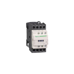
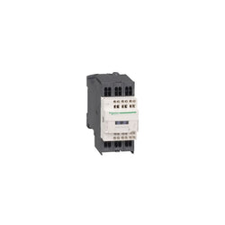
TeSys Deca contactor, 4 poles (4NO), for non-inductive load applications up to 20A/440V AC-1. They can be used to create motor starters for almost any type of application. It provides a low consumption 24V DC coil with transient suppressor module, 1NO+1NC built-in auxiliary contacts (NC mirror contact), connection by screw clamp terminals. For operating rates until 3600 cycles/hour and environments until 60°C, it procures high reliability and durability. Compact (45mm width), DIN-rail mounting or screw fixing. Power contacts have a 20A resistive load rating. Multi standards certified (IEC, UL, CSA, CCC, EAC, Marine). Contactor has one normally open and one normally closed auxiliary contact built-in as standard. The NC contact is mirror certified. Screw clamp terminals are used for load and auxiliary connections. An extensive line of accessories makes it easy to meet the requirements of most applications. The contactor is 3.35 inches tall, 1.77 inches wide and 3.90 inches deep. It weighs 0.80 lbs. Contactor is certified to UL, CSA, IEC, CCC, EAC and Marine standards.
Main
| Characteristic | Value(s) |
|---|---|
| Range | TeSys TeSys Deca |
| Range of Product | TeSys Deca |
| Product or Component Type | Contactor |
| Device short name | LC1D |
| Contactor application | Resistive load |
| Utilisation category | AC-1 |
| Poles description | 4P |
| [Ue] rated operational voltage | Power circuit <= 690 V AC 25...400 Hz Power circuit <= 300 V DC |
| [Ie] rated operational current | 20 A (at <140 °F (60 °C)) at <= 440 V AC AC-1 for power circuit |
| [Uc] control circuit voltage | 24 V DC |
Complementary
| Characteristic | Value(s) |
|---|---|
| Compatibility code | LC1D |
| Pole contact composition | 4 NO |
| Protective cover | With |
| [Ith] conventional free air thermal current | 10 A (at 140 °F (60 °C)) for signalling circuit 20 A (at 140 °F (60 °C)) for power circuit |
| Irms rated making capacity | 140 A AC for signalling circuit conforming to IEC 60947-5-1 250 A DC for signalling circuit conforming to IEC 60947-5-1 250 A at 440 V for power circuit conforming to IEC 60947 |
| Rated breaking capacity | 250 A at 440 V for power circuit conforming to IEC 60947 |
| [Icw] rated short-time withstand current | 30 A 104 °F (40 °C) - 10 min for power circuit 61 A 104 °F (40 °C) - 1 min for power circuit 105 A 104 °F (40 °C) - 10 s for power circuit 210 A 104 °F (40 °C) - 1 s for power circuit 100 A - 1 s for signalling circuit 120 A - 500 ms for signalling circuit 140 A - 100 ms for signalling circuit |
| Associated fuse rating | 10 A gG for signalling circuit conforming to IEC 60947-5-1 25 A gG at <= 690 V coordination type 1 for power circuit 20 A gG at <= 690 V coordination type 2 for power circuit |
| Average impedance | 2.5 mOhm - Ith 20 A 50 Hz for power circuit |
| Power dissipation per pole | 1.56 W AC-1 |
| [Ui] rated insulation voltage | Power circuit 600 V CSA Power circuit 600 V UL Signalling circuit 690 V IEC 60947-1 Signalling circuit 600 V CSA Signalling circuit 600 V UL Power circuit 690 V IEC 60947-4-1 |
| Overvoltage category | III |
| pollution degree | 3 |
| [Uimp] rated impulse withstand voltage | 6 kV IEC 60947 |
| Safety reliability level | B10d = 1369863 cycles contactor with nominal load EN/ISO 13849-1 B10d = 20000000 cycles contactor with mechanical load EN/ISO 13849-1 |
| Mechanical durability | 30 Mcycles |
| Control circuit type | DC low consumption |
| Coil technology | Built-in bidirectional peak limiting diode suppressor |
| Control circuit voltage limits | 0.1...0.3 Uc (-40â¦158 °F (-40â¦70 °C)):drop-out DC 0.8...1.25 Uc (-40â¦140 °F (-40â¦60 °C)):operational DC 1...1.25 Uc (140â¦158 °F (60â¦70 °C)):operational DC |
| Inrush power in W | 2.4 W 68 °F (20 °C)) |
| Hold-in power consumption in W | 2.4 W 68 °F (20 °C) |
| Operating time | 77 ±15 % ms closing 25 ±20 % ms opening |
| Time constant | 40 ms |
| Maximum operating rate | 3600 cyc/h at 60 °C |
| Connections - terminals | Control circuit: screw clamp terminals 2 0.002â¦0.004 in² (1â¦2.5 mm²) - cable stiffness: flexible with cable end Control circuit: screw clamp terminals 1 0.002â¦0.006 in² (1â¦4 mm²) - cable stiffness: flexible without cable end Control circuit: screw clamp terminals 2 0.002â¦0.006 in² (1â¦4 mm²) - cable stiffness: flexible without cable end Control circuit: screw clamp terminals 1 0.002â¦0.006 in² (1â¦4 mm²) - cable stiffness: flexible with cable end Control circuit: screw clamp terminals 1 0.002â¦0.006 in² (1â¦4 mm²) - cable stiffness: solid without cable end Control circuit: screw clamp terminals 2 0.002â¦0.006 in² (1â¦4 mm²) - cable stiffness: solid without cable end Power circuit: screw clamp terminals 1 0.002â¦0.006 in² (1â¦4 mm²) - cable stiffness: flexible without cable end Power circuit: screw clamp terminals 2 0.002â¦0.006 in² (1â¦4 mm²) - cable stiffness: flexible without cable end Power circuit: screw clamp terminals 1 0.002â¦0.006 in² (1â¦4 mm²) - cable stiffness: flexible with cable end Power circuit: screw clamp terminals 2 0.002â¦0.004 in² (1â¦2.5 mm²) - cable stiffness: flexible with cable end Power circuit: screw clamp terminals 1 0.002â¦0.006 in² (1â¦4 mm²) - cable stiffness: solid without cable end Power circuit: screw clamp terminals 2 0.002â¦0.006 in² (1â¦4 mm²) - cable stiffness: solid without cable end |
| Tightening torque | Control circuit 15.05 lbf.in (1.7 N.m) screw clamp terminals flat à 6 mm Control circuit 15.05 lbf.in (1.7 N.m) screw clamp terminals Philips No 2 Power circuit 15.05 lbf.in (1.7 N.m) screw clamp terminals flat à 6 mm Power circuit 15.05 lbf.in (1.7 N.m) screw clamp terminals Philips No 2 Control circuit 15.05 lbf.in (1.7 N.m) screw clamp terminals pozidriv No 2 Power circuit 15.05 lbf.in (1.7 N.m) screw clamp terminals pozidriv No 2 |
| Auxiliary contact composition | 1 NO + 1 NC |
| Auxiliary contacts type | Mechanically linked 1 NO + 1 NC IEC 60947-5-1 Mirror contact 1 NC IEC 60947-4-1 |
| Signalling circuit frequency | 25...400 Hz |
| Minimum switching voltage | 17 V for signalling circuit |
| Minimum switching current | 5 mA for signalling circuit |
| Insulation resistance | > 10 MOhm for signalling circuit |
| Non-overlap time | 1.5 ms on de-energisation between NC and NO contact 1.5 ms on energisation between NC and NO contact |
| Mounting Support | Rail Plate |
C60PV-DC - 2P - 15A - 800 V - B curve

TeSys F contactor, 3 poles (3NO), 185A/690V AC-3, for motor applications up to 90kW@400V. It provides a 380V 50Hz AC coil, bolt terminals for bars or cables with lugs. For high operating rates until 2400 cycles/hour and environments until 55°C, it procures high reliability and durability. It makes installation and maintenance easy thanks to its drawer-mounted coil and a large choice of add-on blocks and accessories (to be ordered separately). Multi standards certified (IEC, UL, CSA, CCC, EAC, Marine), Green Premium compliant (RoHS/REACh).
Main
| Characteristic | Value(s) |
|---|---|
| Range | TeSys |
| Range of Product | TeSys F |
| Product or Component Type | Contactor |
| Device short name | LC1F |
| Contactor application | Motor control Resistive load |
| Utilisation category | AC-3 AC-4 AC-1 |
| Poles description | 3P |
| [Ue] rated operational voltage | <= 460 V DC <= 690 V AC 50/60 Hz |
| [Uc] control circuit voltage | 380 V AC 50 Hz |
| [Ie] rated operational current | 275 A (at <104 °F (40 °C)) at <= 440 V AC-1 185 A (at <131 °F (55 °C)) at <= 440 V AC-3 |
Complementary
| Characteristic | Value(s) |
|---|---|
| [Uimp] rated impulse withstand voltage | 8 kV |
| [Ith] conventional free air thermal current | 275 A (at 104 °F (40 °C)) |
| Rated breaking capacity | 1480 A conforming to IEC 60947-4-1 |
| [Icw] rated short-time withstand current | 1500 A 104 °F (40 °C) - 10 s 920 A 104 °F (40 °C) - 30 s 740 A 104 °F (40 °C) - 1 min 500 A 104 °F (40 °C) - 3 min 400 A 104 °F (40 °C) - 10 min |
| Associated fuse rating | 200 A aM at <= 440 V 315 A gG at <= 440 V |
| Average impedance | 0.33 mOhm - Ith 275 A 50 Hz |
| [Ui] rated insulation voltage | 1000 V IEC 60947-4-1 1500 V VDE 0110 group C |
| Power dissipation per pole | 12 W AC-3 25 W AC-1 |
| Overvoltage category | III |
| power pole contact composition | 3 NO |
| Motor power kW | 90 kW at 380...400 V AC 50/60 Hz (AC-3) 100 kW at 415 V AC 50/60 Hz (AC-3) 100 kW at 440 V AC 50/60 Hz (AC-3) 110 kW at 500 V AC 50/60 Hz (AC-3) 110 kW at 660...690 V AC 50/60 Hz (AC-3) 55 kW at 220...230 V AC 50/60 Hz (AC-3) 33 kW at 400 V AC 50/60 Hz (AC-4) |
| Control circuit voltage limits | Operational 0.85...1.1 Uc 50/60 Hz 131 °F (55 °C)) Drop-out 0.35...0.55 Uc 50/60 Hz 131 °F (55 °C)) |
| Mechanical durability | 10 Mcycles |
| Inrush power in VA | 805 VA, 50 Hz 0.3 68 °F (20 °C)) |
| Hold-in power consumption in VA | 55 VA, 50 Hz 0.3 68 °F (20 °C)) |
| Maximum operating rate | 2400 cyc/h 131 °F (55 °C) |
| Operating time | 20...35 ms closing 7...15 ms opening |
| Connections - terminals | Control circuit screw clamp terminals 1 0.002â¦0.006 in² (1â¦4 mm²)flexible without cable end Control circuit screw clamp terminals 2 0.002â¦0.006 in² (1â¦4 mm²)flexible without cable end Control circuit screw clamp terminals 1 0.002â¦0.006 in² (1â¦4 mm²)flexible with cable end Control circuit screw clamp terminals 2 0.002â¦0.004 in² (1â¦2.5 mm²)flexible with cable end Control circuit screw clamp terminals 1 0.002â¦0.006 in² (1â¦4 mm²)solid without cable end Control circuit screw clamp terminals 2 0.002â¦0.006 in² (1â¦4 mm²)solid without cable end Power circuit bar 2 25 x 3 mm Power circuit lugs-ring terminals 1 0.2 in² (150 mm²) Power circuit connector 1 0.2 in² (150 mm²) Power circuit bolted connection |
| Tightening torque | Control circuit 10.6 lbf.in (1.2 N.m) Power circuit 159.3 lbf.in (18 N.m) |
| Mounting Support | Plate |
| Heat dissipation | 18â¦24 W |
| Standards | EN 60947-1 JIS C8201-4-1 IEC 60947-1 EN 60947-4-1 IEC 60947-4-1 |
| Product Certifications | UL LROS (Lloyds register of shipping) RMRoS CB CCC BV ABS RINA DNV |
| Compatibility code | LC1F |
| Control circuit type | AC 50 Hz |

PLC Direct is not an authorized distributor. We offer a broad range of in-stock products with minimal lead time.

Main
| Characteristic | Value(s) |
|---|---|
| Range | TeSys |
| product name | TeSys D |
| Product or Component Type | Reversing contactor |
| Device short name | LC2D |
| Contactor application | Resistive load Motor control |
| Utilisation category | AC-1 AC-3 AC-3e |
| Device presentation | Preassembled with reversing power busbar |
| Poles description | 3P |
| power pole contact composition | 3 NO |
| [Ue] rated operational voltage | Power circuit <= 690 V AC 25...400 Hz Power circuit <= 300 V DC |
| [Ie] rated operational current | 80 A (at <140 °F (60 °C)) at <= 440 V AC AC-1 for power circuit 65 A (at <140 °F (60 °C)) at <= 440 V AC AC-3 for power circuit 65 A (at <140 °F (60 °C)) at <= 440 V AC AC-3e for power circuit |
| Motor power kW | 18.5 kW at 220...230 V AC 50 Hz 30 kW at 380...400 V AC 50 Hz 37 kW at 415...440 V AC 50 Hz 37 kW at 500 V AC 50 Hz 37 kW at 660...690 V AC 50 Hz |
| motor power HP (UL / CSA) | 40 hp at 460/480 V AC 60 Hz for 3 phase motors 5 hp at 115 V AC 60 Hz for 1 phase motors 10 hp at 230/240 V AC 60 Hz for 1 phase motors 20 hp at 200/208 V AC 60 Hz for 3 phase motors 20 hp at 230/240 V AC 60 Hz for 3 phase motors 50 hp at 575/600 V AC 60 Hz for 3 phase motors |
| Control circuit type | AC 50/60 Hz |
| [Uc] control circuit voltage | 100 V AC 50/60 Hz |
| Auxiliary contact composition | 1 NO + 1 NC |
| [Uimp] rated impulse withstand voltage | 6 kV IEC 60947 |
| Overvoltage category | III |
| [Ith] conventional free air thermal current | 10 A (at 140 °F (60 °C)) for signalling circuit 80 A (at 140 °F (60 °C)) for power circuit |
| Irms rated making capacity | 140 A AC for signalling circuit conforming to IEC 60947-5-1 250 A DC for signalling circuit conforming to IEC 60947-5-1 1000 A at 440 V for power circuit conforming to IEC 60947 |
| Rated breaking capacity | 1000 A at 440 V for power circuit conforming to IEC 60947 |
| [Icw] rated short-time withstand current | 520 A 104 °F (40 °C) - 10 s for power circuit 900 A 104 °F (40 °C) - 1 s for power circuit 110 A 104 °F (40 °C) - 10 min for power circuit 260 A 104 °F (40 °C) - 1 min for power circuit 100 A - 1 s for signalling circuit 120 A - 500 ms for signalling circuit 140 A - 100 ms for signalling circuit |
| Associated fuse rating | 10 A gG for signalling circuit conforming to IEC 60947-5-1 125 A gG at <= 690 V coordination type 1 for power circuit 125 A gG at <= 690 V coordination type 2 for power circuit |
| Average impedance | 1.5 mOhm - Ith 80 A 50 Hz for power circuit |
| [Ui] rated insulation voltage | Power circuit 690 V IEC 60947-4-1 Power circuit 600 V CSA Power circuit 600 V UL Signalling circuit 690 V IEC 60947-1 Signalling circuit 600 V CSA Signalling circuit 600 V UL |
| Electrical durability | 1.45 Mcycles 65 A AC-3 <= 440 V 1.4 Mcycles 80 A AC-1 <= 440 V 1.45 Mcycles 65 A AC-3e <= 440 V |
| Power dissipation per pole | 9.6 W AC-1 6.3 W AC-3 6.3 W AC-3e |
| Front cover | With |
| Interlocking type | Mechanical |
| Mounting Support | Rail Plate |
| Standards | CSA C22.2 No 14 EN 60947-4-1 EN 60947-5-1 IEC 60947-4-1 IEC 60947-5-1 UL 508 |
| Product Certifications | UL CSA RINA GOST CCC DNV LROS (Lloyds register of shipping) GL BV UKCA |
| Connections - terminals | Control circuit screw clamp terminals 1 0.002â¦0.006 in² (1â¦4 mm²)flexible without cable end Control circuit screw clamp terminals 2 0.002â¦0.006 in² (1â¦4 mm²)flexible without cable end Control circuit screw clamp terminals 1 0.002â¦0.006 in² (1â¦4 mm²)flexible with cable end Control circuit screw clamp terminals 2 0.002â¦0.004 in² (1â¦2.5 mm²)flexible with cable end Control circuit screw clamp terminals 1 0.002â¦0.006 in² (1â¦4 mm²)solid Control circuit screw clamp terminals 2 0.002â¦0.006 in² (1â¦4 mm²)solid Power circuit EverLink BTR screw connectors 1 0.002â¦0.05 in² (1â¦35 mm²)flexible without cable end Power circuit EverLink BTR screw connectors 2 0.002â¦0.04 in² (1â¦25 mm²)flexible without cable end Power circuit EverLink BTR screw connectors 1 0.002â¦0.05 in² (1â¦35 mm²)flexible with cable end Power circuit EverLink BTR screw connectors 2 0.002â¦0.04 in² (1â¦25 mm²)flexible with cable end Power circuit EverLink BTR screw connectors 1 0.002â¦0.05 in² (1â¦35 mm²)solid Power circuit EverLink BTR screw connectors 2 0.002â¦0.04 in² (1â¦25 mm²)solid |
| Tightening torque | Control circuit 15.05 lbf.in (1.7 N.m) screw clamp terminals flat à 6 mm Control circuit 15.05 lbf.in (1.7 N.m) screw clamp terminals Philips No 2 Power circuit 70.8 lbf.in (8 N.m) EverLink BTR screw connectors 0.04â¦0.05 in² (25â¦35 mm²) hexagonal 0.2 in (4 mm) Power circuit 44.3 lbf.in (5 N.m) EverLink BTR screw connectors 0.002â¦0.04 in² (1â¦25 mm²) hexagonal 0.2 in (4 mm) |
| Operating time | 4...19 ms opening 12...26 ms closing |
| Safety reliability level | B10d = 1369863 cycles contactor with nominal load EN/ISO 13849-1 B10d = 20000000 cycles contactor with mechanical load EN/ISO 13849-1 |
| Mechanical durability | 6 Mcycles |
| Maximum operating rate | 3600 cyc/h 140 °F (60 °C) |
Complementary
| Characteristic | Value(s) |
|---|---|
| Coil technology | Without built-in suppressor module |
| Control circuit voltage limits | 0.3...0.6 Uc (-40â¦158 °F (-40â¦70 °C)):drop-out AC 50/60 Hz 0.8...1.1 Uc (-40â¦140 °F (-40â¦60 °C)):operational AC 50 Hz 0.85...1.1 Uc (-40â¦140 °F (-40â¦60 °C)):operational AC 60 Hz 1...1.1 Uc (140â¦158 °F (60â¦70 °C)):operational AC 50/60 Hz |
| Inrush power in VA | 140 VA 60 Hz cos phi 0.75 (at 68 °F (20 °C)) 160 VA 50 Hz cos phi 0.75 (at 68 °F (20 °C)) |
| Hold-in power consumption in VA | 13 VA 60 Hz cos phi 0.3 (at 68 °F (20 °C)) 15 VA 50 Hz cos phi 0.3 (at 68 °F (20 °C)) |
| Heat dissipation | 4â¦5 W 50/60 Hz |
| Auxiliary contacts type | Mechanically linked 1 NO + 1 NC IEC 60947-5-1 Mirror contact 1 NC IEC 60947-4-1 |
| Signalling circuit frequency | 25...400 Hz |
| Minimum switching current | 5 mA for signalling circuit |
| Minimum switching voltage | 17 V for signalling circuit |
| Non-overlap time | 1.5 ms on de-energisation between NC and NO contact 1.5 ms on energisation between NC and NO contact |
| Insulation resistance | > 10 MOhm for signalling circuit |

Motor circuit breaker, TeSys GV2, 3P, 13-18 A, thermal magnetic, spring terminals

This Acti9 iID is a modular and reliable residual current circuit breaker (RCCB). It is a 4P circuit breaker with 63A In rated current, 30mA earth leakage sensitivity and A-SI type protection class. This product protects against electrical shock by direct or indirect contact and fire hazards. It performs the function of disconnection of electrical circuits in case of earth fault. Its unique Visitrip indicator reduces intervention time by showing the faulty device with a mechanical indicator on front face. This product also has a VisiSafe window with a green strip on the toggle indicating full opening of the poles allowing downstream maintenance This product is compliant with EN/IEC 61008-1 standard. The (Im/IÎm) rated breaking and making short circuit capacity is 1500A. The (Inc/IÎc) conditional rated short circuit current is 10kA. It has an electrical endurance going up to 15000 cycles and a mechanical endurance going up to 20000 cycles. The Ue operational voltage is 380VAC to 415VAC. The Ui rated insulation voltage is 500VAC. The Uimp rated impulse withstand voltage is 6kV. The frequency is 50Hz or 60Hz. It is DIN rail mountable. The width in 9mm pitches is 8. The product colour is white (RAL9003). The dimensions are (W) 72mm x (H) 91mm x (D) 73.5mm. The weight is 0.37kg. According to IEC 60529 standard, the degree of protection is IP20 and IP40 in enclosure. The operating temperature is from -25°C to 60°C. The storage temperature is from -40°C to 85°C.
Main
| Characteristic | Value(s) |
|---|---|
| Range | Acti9 |
| product name | Acti9 iID |
| Product or component type | Residual current circuit breaker (RCCB) |
| Device short name | iID |
| Poles description | 4P |
| Neutral position | Left |
| [In] rated current | 63 A |
| Network type | AC |
| Earth-leakage sensitivity | 30 mA |
| Earth-leakage protection time delay | Instantaneous |
| Earth-leakage protection class | Type A-SI (Super Immunised) |
Complementary
| Characteristic | Value(s) |
|---|---|
| Device location in system | Outgoer |
| Network frequency | 50/60 Hz |
| [Ue] rated operational voltage | 380...415 V AC 50/60 Hz |
| Residual current tripping technology | Voltage independent |
| Rated breaking and making capacity | Idm 1500 A Im 1500 A |
| Rated conditional short-circuit current | 10 kA |
| [Ui] rated insulation voltage | 500 V AC 50/60 Hz |
| [Uimp] rated impulse withstand voltage | 6 kV |
| Surge current | 3000 A |
| Contact position indicator | Yes |
| control type | Toggle |
| Mounting mode | Clip-on |
| Mounting support | DIN rail |
| 9 mm pitches | 8 |
| Height | 91 mm |
| Width | 72 mm |
| Depth | 73.5 mm |
| Product weight | 0.37 kg |
| Colour | White |
| Mechanical durability | 20000 cycles |
| Electrical durability | AC-1: 15000 cycles |
| Locking options description | Padlocking device |
| Connections - terminals | Single terminal top or bottom 1â¦35 mm² rigid Single terminal top or bottom 1â¦25 mm² flexible Single terminal top or bottom 1â¦25 mm² flexible with ferrule |
| Wire stripping length | 14 mm for top or bottom connection |
| Tightening torque | 3.5 N.m top or bottom |
TeSys D contactor - 3P(3 NO) - AC-3 - <= 440 V 12 A - 380 V AC coil


DIN socket iPC -2P+E -16A-250VAC-NFC15100 -french std-with volt.pres.indic.light

This Acti9 iC40N product is a low voltage miniature circuit breaker (MCB). It is a 3P+N circuit breaker with 3 protected poles and 6A In rated current and C tripping curve. The rated short circuit breaking capacity goes up to 10kA at 400VAC conforming to EN/IEC 60947-2 standard and 6000A at 400VAC conforming to EN/IEC 60898-1 standard. This product complies with both industrial standard EN/IEC 60898-1 and residential standard EN/IEC 60947-2. This miniature circuit breaker combines functions of circuit protection against short circuit and overload current, control and isolation. The installation and cabling are simplified with clip on function as well as ease of maintenance. It has an electrical endurance going up to 20000 cycles and a mechanical endurance going up to 20000 cycles. The Ue operational voltage is 400VAC. The Ui rated insulation voltage is 440VAC. The Uimp rated impulse withstand voltage is 4kV. The operating frequency is 50Hz or 60Hz. It can be mounted on DIN rail for modular installation. Its width is 6 pitches of 9mm. Pollution degree is 3. The product colour is white (RAL9003). The dimensions are (W) 54mm x (H) 85mm x (D) 74mm. The weight is 345g. According to IEC 60529 standard, the degree of protection is IP20 and IP40 in enclosure. The operating temperature is -25°C to 70°C. The storage temperature is -40°C to 85°C.
Main
| Characteristic | Value(s) |
|---|---|
| Range | Acti9 |
| product name | Acti9 iC40 |
| Product or component type | Miniature circuit-breaker |
| Device short name | iC40N |
| Device application | Distribution |
| Poles description | 3P + N |
| Number of protected poles | 3 |
| Neutral position | Left |
| [In] rated current | 6 A |
| Network type | AC |
| Trip unit technology | Thermal-magnetic |
| Curve code | C |
| Breaking capacity | 10 kA Icu at 400 V AC 50/60 Hz conforming to EN/IEC 60947-2 6000 A Icn at 400 V AC 50/60 Hz conforming to EN/IEC 60898-1 |
| Suitability for isolation | Yes conforming to EN/IEC 60947-2 |
| Quality labels | IMQ |
Complementary
| Characteristic | Value(s) |
|---|---|
| Network frequency | 50/60 Hz |
| [Ue] rated operational voltage | 400 V AC 50/60 Hz |
| Magnetic tripping limit | 5...10 x In conforming to EN/IEC 60898-1 8 x In +/- 20 % conforming to EN/IEC 60947-2 |
| [Ics] rated service breaking capacity | 6000 A 100 % x Icn at 400 V AC 50/60 Hz conforming to EN/IEC 60898-1 7.5 kA 75 % x Icn at 400 V AC 50/60 Hz conforming to EN/IEC 60947-2 |
| Limitation class | 3 conforming to EN/IEC 60898-1 |
| [Ui] rated insulation voltage | 440 V AC 50/60 Hz conforming to EN/IEC 60947-2 |
| [Uimp] rated impulse withstand voltage | 4 kV conforming to EN/IEC 60947-2 |
| Contact position indicator | Yes |
| control type | Toggle |
| Local signalling | ON/OFF indication Trip indicator |
| Mounting mode | Clip-on |
| Mounting support | DIN rail |
| 9 mm pitches | 6 |
| Height | 85 mm |
| Width | 54 mm |
| Depth | 74 mm |
| Product weight | 345 g |
| Colour | White |
| Mechanical durability | 20000 cycles |
| Electrical durability | 20000 cycles |
| Locking options description | Padlocking device |
| Connections - terminals | Tunnel type terminals top or bottom 1â¦10 mm² flexible Tunnel type terminals top or bottom 1â¦16 mm² rigid |
| Wire stripping length | 14 mm for top or bottom connection |
| Tightening torque | 2 N.m top or bottom |
| Earth-leakage protection | Separate block |
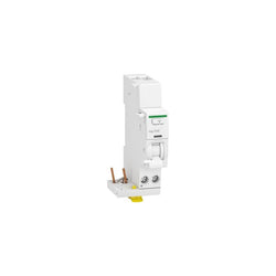
add-on residual current devices, Acti9 Vigi iC40, 1P+N, 25 A, 30 mA, AC type


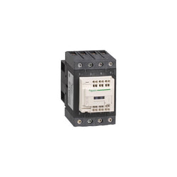
"TeSys Deca contactor, 3 poles(3NO) for category AC-3 applications up to 115A @440V." "It provides with 220V 50 Hz coil, with 1NO+1NC auxiliary contacts, power and control connections by screw clamp terminals." It procures high reliability and durability with 8 Mcycles mechanical durability and 0.95 Mcycles electrical durability. It provides IP20 protection on front face conforming to IEC 60529. It can cover -40°C to 60°C operation temperature and without derating under 3000m altitude. "Designed for demanding applications with maximum operating rates up to 1200 cycles per hour under maximum 60°C." The dimension is 158mm x 120mm x 136mm (H x W x D), mounting on rail or plate. Multi standards certified(CCC,DNV,GL,CSA,GOST,BV,UL,LROS,RINA,UKCA).
Main
| Characteristic | Value(s) |
|---|---|
| Range | TeSys |
| Range of product | TeSys Deca |
| Product or component type | Contactor |
| Device short name | LC1D |
| Contactor application | Resistive load Motor control |
| Utilisation category | AC-4 AC-1 AC-3 AC-3e |
| Poles description | 3P |
| [Ue] rated operational voltage | Power circuit: <= 1000 V AC 25...400 Hz Power circuit: <= 300 V DC |
| [Ie] rated operational current | 200 A (at <60 °C) at <= 440 V AC AC-1 for power circuit 115 A (at <60 °C) at <= 440 V AC AC-3 for power circuit 115 A (at <60 °C) at <= 440 V AC AC-3e for power circuit |
| [Uc] control circuit voltage | 220 V AC 50 Hz |
Complementary
| Characteristic | Value(s) |
|---|---|
| Motor power kW | 30 kW at 220...230 V AC 50/60 Hz (AC-3) 55 kW at 380...400 V AC 50/60 Hz (AC-3) 59 kW at 415...440 V AC 50/60 Hz (AC-3) 75 kW at 500 V AC 50/60 Hz (AC-3) 80 kW at 660...690 V AC 50/60 Hz (AC-3) 65 kW at 1000 V AC 50/60 Hz (AC-3) 18.5 kW at 400 V AC 50/60 Hz (AC-4) 30 kW at 220...230 V AC 50/60 Hz (AC-3e) 55 kW at 380...400 V AC 50/60 Hz (AC-3e) 59 kW at 415...440 V AC 50/60 Hz (AC-3e) 75 kW at 500 V AC 50/60 Hz (AC-3e) 80 kW at 660...690 V AC 50/60 Hz (AC-3e) 65 kW at 1000 V AC 50/60 Hz (AC-3e) |
| Motor power hp | 30 hp at 200/208 V AC 50/60 Hz for 3 phases motors 40 hp at 230/240 V AC 50/60 Hz for 3 phases motors 75 hp at 460/480 V AC 50/60 Hz for 3 phases motors 100 hp at 575/600 V AC 50/60 Hz for 3 phases motors |
| Compatibility code | LC1D |
| Pole contact composition | 3 NO |
| Protective cover | With |
| [Ith] conventional free air thermal current | 200 A (at 60 °C) for power circuit |
| Irms rated making capacity | 1260 A at 440 V for power circuit conforming to IEC 60947 140 A AC for signalling circuit conforming to IEC 60947-5-1 250 A DC for signalling circuit conforming to IEC 60947-5-1 |
| Rated breaking capacity | 1100 A at 440 V for power circuit conforming to IEC 60947 |
| [Icw] rated short-time withstand current | 250 A 40 °C - 10 min for power circuit 550 A 40 °C - 1 min for power circuit 950 A 40 °C - 10 s for power circuit 1100 A 40 °C - 1 s for power circuit 100 A - 1 s for signalling circuit 120 A - 500 ms for signalling circuit 140 A - 100 ms for signalling circuit |
| Associated fuse rating | 250 A gG at <= 690 V coordination type 1 for power circuit 200 A gG at <= 690 V coordination type 2 for power circuit 10 A gG for signalling circuit |
| Average impedance | 0.6 mOhm - Ith 200 A 50 Hz for power circuit |
| Power dissipation per pole | 24 W AC-1 7.9 W AC-3 7.9 W AC-3e |
| [Ui] rated insulation voltage | Power circuit: 600 V CSA certified Power circuit: 600 V UL certified Power circuit: 1000 V conforming to IEC 60947-4-1 Signalling circuit: 690 V conforming to IEC 60947-1 Signalling circuit: 600 V CSA certified Signalling circuit: 600 V UL certified |
| Overvoltage category | III |
| pollution degree | 3 |
| [Uimp] rated impulse withstand voltage | 8 kV conforming to IEC 60947 |
| Safety reliability level | B10d = 684932 cycles contactor with nominal load conforming to EN/ISO 13849-1 B10d = 10000000 cycles contactor with mechanical load conforming to EN/ISO 13849-1 |
| Mechanical durability | 8 Mcycles |
| Electrical durability | 0.8 Mcycles 200 A AC-1 at Ue <= 440 V 0.95 Mcycles 115 A AC-3 at Ue <= 440 V 0.95 Mcycles 115 A AC-3e at Ue <= 440 V |
| Control circuit type | AC at 50 Hz |
| Coil technology | Without built-in suppressor module |
| Control circuit voltage limits | 0.3...0.6 Uc (-40â¦70 °C):drop-out AC 50 Hz 0.85...1.1 Uc (-40â¦55 °C):operational AC 50 Hz 1...1.1 Uc (55â¦70 °C):operational AC 50 Hz |
| Inrush power in VA | 300 VA 50 Hz cos phi 0.8 (at 20 °C) |
| Hold-in power consumption in VA | 22 VA 50 Hz cos phi 0.3 (at 20 °C) |
| Heat dissipation | 3â¦8 W at 50 Hz |
| Operating time | 6...20 ms opening 20...50 ms closing |
| Maximum operating rate | 2400 cyc/h at 60 °C |
| Connections - terminals | Control circuit: lugs-ring terminals - external diameter: 8 mm Power circuit: lugs-ring terminals - external diameter: 25 mm Power circuit: bars 1 - busbar cross section: 5 x 25 mm |
| Tightening torque | Control circuit: 1.2 N.m - on lugs-ring terminals - with screwdriver flat à 6 mm M3.5 Control circuit: 1.2 N.m - on lugs-ring terminals - with screwdriver Philips No 2 M3.5 Power circuit: 12 N.m - on lugs-ring terminals hexagonal screw head 13 mm M8 Power circuit: 12 N.m - on bars hexagonal screw head 13 mm M8 Control circuit: 1.2 N.m - on lugs-ring terminals - with screwdriver pozidriv No 2 M3.5 |
| Auxiliary contact composition | 1 NO + 1 NC |
| Auxiliary contacts type | type mechanically linked 1 NO + 1 NC conforming to IEC 60947-5-1 type mirror contact 1 NC conforming to IEC 60947-4-1 |
| Signalling circuit frequency | 25...400 Hz |
| Minimum switching voltage | 17 V for signalling circuit |
| Minimum switching current | 5 mA for signalling circuit |
| Insulation resistance | > 10 MOhm for signalling circuit |
| Non-overlap time | 1.5 ms on de-energisation between NC and NO contact 1.5 ms on energisation between NC and NO contact |
| Mounting support | Rail Plate |
Main
| Characteristic | Value(s) |
|---|---|
| Range | TeSys |
| Range of Product | TeSys Deca |
| Product or Component Type | Contactor |
| Device short name | LC1D |
| Contactor application | Resistive load |
| Utilisation category | AC-1 |
| Poles description | 4P |
| [Ue] rated operational voltage | Power circuit <= 690 V AC 25...400 Hz Power circuit <= 300 V DC |
| [Ie] rated operational current | 80 A (at <140 °F (60 °C)) at <= 440 V AC AC-1 for power circuit |
| [Uc] control circuit voltage | 400 V AC 50/60 Hz |
Complementary
| Characteristic | Value(s) |
|---|---|
| Compatibility code | LC1D |
| Pole contact composition | 4 NO |
| Protective cover | With |
| [Ith] conventional free air thermal current | 10 A (at 140 °F (60 °C)) for signalling circuit 80 A (at 140 °F (60 °C)) for power circuit |
| Irms rated making capacity | 140 A AC for signalling circuit conforming to IEC 60947-5-1 250 A DC for signalling circuit conforming to IEC 60947-5-1 1000 A at 440 V for power circuit conforming to IEC 60947 |
| Rated breaking capacity | 1000 A at 440 V for power circuit conforming to IEC 60947 |
| [Icw] rated short-time withstand current | 640 A 104 °F (40 °C) - 10 s for power circuit 900 A 104 °F (40 °C) - 1 s for power circuit 110 A 104 °F (40 °C) - 10 min for power circuit 260 A 104 °F (40 °C) - 1 min for power circuit 100 A - 1 s for signalling circuit 120 A - 500 ms for signalling circuit 140 A - 100 ms for signalling circuit |
| Associated fuse rating | 10 A gG for signalling circuit conforming to IEC 60947-5-1 125 A gG at <= 690 V coordination type 1 for power circuit 125 A gG at <= 690 V coordination type 2 for power circuit |
| Average impedance | 1.6 mOhm - Ith 80 A 50 Hz for power circuit |
| Power dissipation per pole | 10.2 W AC-1 |
| [Ui] rated insulation voltage | Power circuit 600 V CSA Power circuit 600 V UL Signalling circuit 690 V IEC 60947-1 Signalling circuit 600 V CSA Signalling circuit 600 V UL Power circuit 690 V IEC 60947-4-1 |
| Overvoltage category | III |
| pollution degree | 3 |
| [Uimp] rated impulse withstand voltage | 6 kV IEC 60947 |
| Safety reliability level | B10d = 1369863 cycles contactor with nominal load EN/ISO 13849-1 B10d = 20000000 cycles contactor with mechanical load EN/ISO 13849-1 |
| Mechanical durability | 6 Mcycles |
| Electrical durability | 1.4 Mcycles 80 A AC-1 <= 440 V |
| Control circuit type | AC 50/60 Hz |
| Coil technology | Without built-in suppressor module |
| Control circuit voltage limits | 0.3...0.6 Uc (-40â¦158 °F (-40â¦70 °C)):drop-out AC 50/60 Hz 0.8...1.1 Uc (-40â¦140 °F (-40â¦60 °C)):operational AC 50 Hz 0.85...1.1 Uc (-40â¦140 °F (-40â¦60 °C)):operational AC 60 Hz 1...1.1 Uc (140â¦158 °F (60â¦70 °C)):operational AC 50/60 Hz |
| Inrush power in VA | 140 VA 60 Hz cos phi 0.75 (at 68 °F (20 °C)) 160 VA 50 Hz cos phi 0.75 (at 68 °F (20 °C)) |
| Hold-in power consumption in VA | 13 VA 60 Hz cos phi 0.3 (at 68 °F (20 °C)) 15 VA 50 Hz cos phi 0.3 (at 68 °F (20 °C)) |
| Heat dissipation | 4â¦5 W at 50/60 Hz |
| Operating time | 4...19 ms opening 12...26 ms closing |
| Connections - terminals | Control circuit: spring terminals 1 0.004 in² (2.5 mm²) - cable stiffness: flexible without cable end Control circuit: spring terminals 2 0.004 in² (2.5 mm²) - cable stiffness: flexible without cable end Power circuit: EverLink BTR screw connectors 1 0.002â¦0.05 in² (1â¦35 mm²) - cable stiffness: flexible without cable end Power circuit: EverLink BTR screw connectors 2 0.002â¦0.04 in² (1â¦25 mm²) - cable stiffness: flexible without cable end Power circuit: EverLink BTR screw connectors 1 0.002â¦0.05 in² (1â¦35 mm²) - cable stiffness: flexible with cable end Power circuit: EverLink BTR screw connectors 2 0.002â¦0.04 in² (1â¦25 mm²) - cable stiffness: flexible with cable end Power circuit: EverLink BTR screw connectors 1 0.002â¦0.05 in² (1â¦35 mm²) - cable stiffness: solid without cable end Power circuit: EverLink BTR screw connectors 2 0.002â¦0.04 in² (1â¦25 mm²) - cable stiffness: solid without cable end |
| Tightening torque | Power circuit 70.8 lbf.in (8 N.m) screw clamp terminals 0.04â¦0.05 in² (25â¦35 mm²) hexagonal 0.2 in (4 mm) Power circuit 44.3 lbf.in (5 N.m) screw clamp terminals 0.004â¦0.04 in² (2.5â¦25 mm²) hexagonal 0.2 in (4 mm) |
| Auxiliary contact composition | 1 NO + 1 NC |
| Auxiliary contacts type | Mechanically linked 1 NO + 1 NC IEC 60947-5-1 Mirror contact 1 NC IEC 60947-4-1 |
| Signalling circuit frequency | 25...400 Hz |
| Minimum switching voltage | 17 V for signalling circuit |
| Minimum switching current | 5 mA for signalling circuit |
| Insulation resistance | > 10 MOhm for signalling circuit |
| Non-overlap time | 1.5 ms on de-energisation between NC and NO contact 1.5 ms on energisation between NC and NO contact |
| Mounting Support | Plate Rail |
TeSys K contactor - 3P - AC-3 <= 440 V 16 A - 1 NC aux. - 380...400 V AC coil