1 year warranty


Safety relay for emergency stop and safety door monitoring up to SIL 3 or Cat. 4, PL e according to EN ISO 13849, automatic or manual activation, 2 N/O contacts with dropout delay of 0.1 s to 30 s, plug-in screw connection terminal block

ABB EcoSolutions
Material Compliance
Environmental
Ordering
Dimensions
Container Information
Additional Information
Technical
Certificates and Declarations
External Classifications and Standards

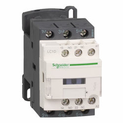
TeSys LR9G 225A thermal overload relay is compatible with TeSys Giga high power contactor, push-in control connection. It provides phase imbalance, phase failure, in-built ground-fault and single-phase loads protections. It is available for manual and auto reset options and LED indicator for Motor ON and pre-trip alarm. Tripping classes is selectable from class 5E to class 30E to suit different application needs from fast tripping, general purpose and high inertia loads. It is suitable for independent mounting or direct mounting with LC1G contactors. It provides IP2x protection in Front face with shrouds conforming to IEC 60529 and VDE 0106. It can cover -25°C to 60°C operation ambient air temperature without derating up to 3000m altitude. Multi standards certified (CE,CB,CCC,cULus,EAC,KC,RCM,Marine). Unique QR code provides quick access to complete product data.
Main
| Characteristic | Value(s) |
|---|---|
| Range | TeSys |
| product name | TeSys LRG |
| Product or Component Type | Electronic thermal overload relay |
| Device short name | LR9G |
| Relay application | Motor protection |
| Network type | AC |
| Thermal overload class | Class 5E...30E IEC 60947-4-1 |
| Thermal protection adjustment range | 57â¦225 A |
Complementary
| Characteristic | Value(s) |
|---|---|
| Network Frequency | 30...60 Hz 100 Hz |
| Overvoltage category | III |
| Tripping threshold | 1.125 +/- 0.07 In IEC 60947-4-1 |
| Protection type | Ground fault protection 0â¦1 s - alarm circuit IEC 60947-4-1 Ground fault protection 0â¦1 s - alarm circuit UL 60947-4-1 Phase loss 0â¦4 s - alarm circuit Phase imbalance 0â¦5 s - alarm circuit IEC 60947-4-1 Phase imbalance 0â¦5 s - alarm circuit UL 60947-4-1 |
| Local signalling | LED Trip indicator |
| Contacts type and composition | 1 NO + 1 NC |
| [Ith] conventional free air thermal current | 5 A |
| [Uc] control circuit voltage | 24...500 V AC 50/60 Hz 24...250 V DC |
| [Ue] rated operational voltage | 1000 V AC 50/60 Hz |
| [Uimp] rated impulse withstand voltage | 8 kV |
| Reset | Automatic reset Manual |
| Mechanical durability | 7000 cycles |
| Surge withstand | 4 kV |
| Electromagnetic compatibility | EMC immunity conforming to IEC 60947-4-1 Emission tests criteria A conforming to IEC 60947-4-1 Immunity to radiated radio-electrical interference - test level: 20 V/m conforming to EN/IEC 61000-4-3 Voltage dips and interruptions immunity test conforming to SEMI F47 |
| Connections - terminals | Power circuit: bar - busbar cross section: 25 x 6 mm Power circuit: lugs-ring terminals 1 0.3 in² (185 mm²) Control circuit: push-in 1 0.0003â¦0.004 in² (0.2â¦2.5 mm²) - cable stiffness: solid stranded without cable end Control circuit: push-in 1 0.0004â¦0.004 in² (0.25â¦2.5 mm²) - cable stiffness: flexible with cable end Control circuit: push-in 2 0.0008â¦0.002 in² (0.5â¦1.0 mm²) with cable end |
| Tightening torque | 18 N.m |
| Mounting support | Direct on contactor Plate |
| Standards | EN/IEC 60947-4-1 EN/IEC 60947-5-1 UL 60947-4-1 CSA C22.2 No 60947-4-1 JIS C8201-4-1 JIS C8201-5-1 IEC 60335-1:Clause 30.2 IEC 60335-2-40:Annex JJ UL 60335-2-40:Annex JJ UL 60335-1 |
| Product Certifications | CB Scheme CCC cULus UKCA ATEX EU-RO-MR by DNV-GL EAC |
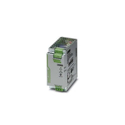
Primary-switched MINI DC/DC converter for DIN rail mounting, input: 1-phase, output: 5 - 15 V DC/2 A
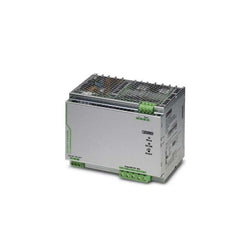
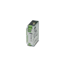
Primary-switched QUINT POWER power supply with free choice of output characteristic curve, SFB�(selective fuse breaking) technology, and NFC interface, input: 3-phase,�output:�24�V�DC/10 A

Material Compliance
Environmental
Ordering
Dimensions
Container Information
Additional Information
Technical
Certificates and Declarations
External Classifications and Standards

Material Compliance
Environmental
Ordering
Dimensions
Container Information
Additional Information
Technical
Certificates and Declarations
External Classifications and Standards

| Product | |
| Article Number (Market Facing Number) | 6EP13363BA10 | 6EP13363BA10 |
| Product Description | SITOP PSU8200 20 A stabilized power supply input: 120-230 V AC 110-220 V DC output: 24 V DC/20 A |
| Product family | 1-phase, 24 V DC |
| Product Lifecycle (PLM) | PM300:Active Product |
| Additional Product Information | |
| EAN | 4025515152583 |
| UPC | 662643545487 |
| Commodity Code | 85044083 |
| LKZ_FDB/ CatalogID | KT10-PE |
| Product Group | 4213 |
| Group Code | R315 |
| Country of origin | Romania |
| SCIP number | Not available |
| Delivery information | |
| Net Weight (lb) | 2.337 lb |
| Package size unit of measure | Inch |
| Packaging Quantity | 1 |

| Product | |
| Article Number (Market Facing Number) | 3RW40241BB14 | 3RW40241BB14 |
| Product Description | SIRIUS soft starter S0 12.5 A, 5.5 kW/400 V, 40 °C 200-480 V AC, 110-230 V AC/DC Screw terminals |
| Product family | 3RW40 soft starters |
| Product Lifecycle (PLM) | PM300:Active Product |
| Additional Product Information | |
| EAN | 4011209691582 |
| UPC | Not available |
| Commodity Code | 85371098 |
| LKZ_FDB/ CatalogID | CC-IC10 |
| Product Group | 3727 |
| Group Code | R711 |
| Country of origin | Czech Republic |
| SCIP number | Not available |
| Delivery information | |
| Net Weight (lb) | 1.532 lb |
| Package size unit of measure | in |
| Packaging Quantity | 1 |
TeSys D contactor - 3P(3 NO) - AC-3 - <= 440 V 50 A - 24 V DC standard coil

| Product | |
| Article Number (Market Facing Number) | 6EP13362BA00 | 6EP13362BA00 |
| Product Description | SITOP power 20 A, Stabilized power supply input: 120/230 V AC, output: 24 V DC/20 A |
| Product family | Not available |
| Product Lifecycle (PLM) | PM500:Discontinued Product or end of PLM & Support |
| Additional Product Information | |
| EAN | 4025515150312 |
| UPC | 754554524023 |
| Commodity Code | 85044090 |
| LKZ_FDB/ CatalogID | KT10-PE |
| Product Group | 4741 |
| Group Code | R315 |
| Country of origin | Romania |
| SCIP number | Not available |
| Delivery information | |
| Net Weight (lb) | 5.291 lb |
| Package size unit of measure | Inch |
| Packaging Quantity | 1 |
| Product | |
| Article Number (Market Facing Number) | 6EP34377SB003AX0 | 6EP34377SB003AX0 |
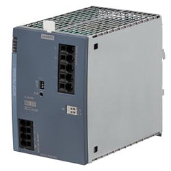
| Product Description | SITOP PSU6200 24 V/40 A stabilized power supply input: 400 - 500 V AC output: 24 V DC/40 A with diagnostic interface |
| Product family | 3-phase, 24 V DC |
| Product Lifecycle (PLM) | PM300:Active Product |
| Additional Product Information | |
| EAN | 4025515155362 |
| UPC | 195125269767 |
| Commodity Code | 85044083 |
| LKZ_FDB/ CatalogID | KT10-PE |
| Product Group | 4D71 |
| Group Code | R315 |
| Country of origin | Romania |
| SCIP number | 64973416-3eb2-46f9-93e6-1f8561ea2c27 |
| Delivery information | |
| Net Weight (lb) | 3.748 lb |
| Package size unit of measure | Inch |
| Packaging Quantity | 1 |
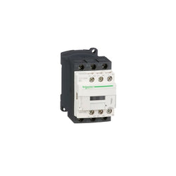
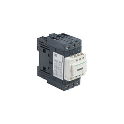
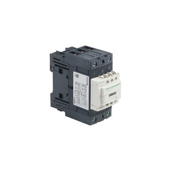
TeSys Deca contactor, 3 poles (3NO), for motor control applications up to 9A/690V AC-3/3e (4kW@400V). They can be used to create motor starters for almost any type of application. It provides a 24V DC coil with transient suppressor module, 1NO+1NC built-in auxiliary contacts (NC mirror certified), connection by screw clamp terminals. For operating rates until 3600 cycles/hour and environments until 60°C, it procures high reliability and durability to demanding applications. Compact (45mm width), DIN-rail mounting or screw fixing. Contactor is rated for 20HP at 200-208VAC, 25HP at 240VAC, 60HP at 480VAC and 60HP at 600VAC three phase. Multi standards certified (IEC, UL, CSA, CCC, EAC, Marine). When used with a 480VAC up to 35A circuit breaker, this contactor can have a SCCR up to 85kA. When used with up to a 600VAC 25A Class J or CC fuse, this contactor can have a SCCR up to 100kA. Contactor is supplied with a 24 VDC coil with transient suppressor module. Contactor has one normally open and one normally closed auxiliary contact built-in as standard. The NC contact is mirror certified. Screw clamp terminals are used for load and auxiliary connections. An extensive line of accessories makes it easy to meet the requirements of most applications. The contactor is 3.15 inches tall, 1.77 inches wide and 3.39 inches deep. It weighs 0.71 lbs. Contactor is certified to UL, CSA, IEC, CCC, EAC and Marine standards.
Main
| Characteristic | Value(s) |
|---|---|
| Range of Product | TeSys Deca |
| Product or Component Type | Contactor |
| Device short name | LC1D |
| Contactor application | Motor control Resistive load |
| Utilisation category | AC-4 AC-1 AC-3 AC-3e |
| Poles description | 3P |
| [Ue] rated operational voltage | Power circuit <= 690 V AC 25...400 Hz Power circuit <= 300 V DC |
| [Ie] rated operational current | 9 A (at <140 °F (60 °C)) at <= 440 V AC AC-3 for power circuit 25 A (at <140 °F (60 °C)) at <= 440 V AC AC-1 for power circuit 9 A (at <140 °F (60 °C)) at <= 440 V AC AC-3e for power circuit |
| [Uc] control circuit voltage | 24 V DC |
Complementary
| Characteristic | Value(s) |
|---|---|
| Motor power kW | 2.2 kW at 220...230 V AC 50/60 Hz (AC-3) 4 kW at 380...400 V AC 50/60 Hz (AC-3) 4 kW at 415...440 V AC 50/60 Hz (AC-3) 5.5 kW at 500 V AC 50/60 Hz (AC-3) 5.5 kW at 660...690 V AC 50/60 Hz (AC-3) 2.2 kW at 400 V AC 50/60 Hz (AC-4) 2.2 kW at 220...230 V AC 50/60 Hz (AC-3e) 4 kW at 380...400 V AC 50/60 Hz (AC-3e) 4 kW at 415...440 V AC 50/60 Hz (AC-3e) 5.5 kW at 500 V AC 50/60 Hz (AC-3e) 5.5 kW at 660...690 V AC 50/60 Hz (AC-3e) |
| Maximum Horse Power Rating | 1 hp at 230/240 V AC 50/60 Hz for 1 phase motors 2 hp at 200/208 V AC 50/60 Hz for 3 phase motors 2 hp at 230/240 V AC 50/60 Hz for 3 phase motors 5 hp at 460/480 V AC 50/60 Hz for 3 phase motors 7.5 hp at 575/600 V AC 50/60 Hz for 3 phase motors 0.33 hp at 115 V AC 50/60 Hz for 1 phase motors |
| Compatibility code | LC1D |
| Pole contact composition | 3 NO |
| Protective cover | With |
| [Ith] conventional free air thermal current | 25 A (at 140 °F (60 °C)) for power circuit 10 A (at 140 °F (60 °C)) for signalling circuit |
| Irms rated making capacity | 250 A at 440 V for power circuit conforming to IEC 60947 140 A AC for signalling circuit conforming to IEC 60947-5-1 250 A DC for signalling circuit conforming to IEC 60947-5-1 |
| Rated breaking capacity | 250 A at 440 V for power circuit conforming to IEC 60947 |
| [Icw] rated short-time withstand current | 105 A 104 °F (40 °C) - 10 s for power circuit 210 A 104 °F (40 °C) - 1 s for power circuit 30 A 104 °F (40 °C) - 10 min for power circuit 61 A 104 °F (40 °C) - 1 min for power circuit 100 A - 1 s for signalling circuit 120 A - 500 ms for signalling circuit 140 A - 100 ms for signalling circuit |
| Associated fuse rating | 10 A gG for signalling circuit conforming to IEC 60947-5-1 25 A gG at <= 690 V coordination type 1 for power circuit 20 A gG at <= 690 V coordination type 2 for power circuit |
| Average impedance | 2.5 mOhm - Ith 25 A 50 Hz for power circuit |
| Power dissipation per pole | 1.56 W AC-1 0.2 W AC-3 0.2 W AC-3e |
| [Ui] rated insulation voltage | Power circuit 690 V IEC 60947-4-1 Power circuit 600 V CSA Power circuit 600 V UL Signalling circuit 690 V IEC 60947-1 Signalling circuit 600 V CSA Signalling circuit 600 V UL |
| Overvoltage category | III |
| pollution degree | 3 |
| [Uimp] rated impulse withstand voltage | 6 kV IEC 60947 |
| Safety reliability level | B10d = 1369863 cycles contactor with nominal load EN/ISO 13849-1 B10d = 20000000 cycles contactor with mechanical load EN/ISO 13849-1 |
| Mechanical durability | 30 Mcycles |
| Electrical durability | 0.6 Mcycles 25 A AC-1 <= 440 V 2 Mcycles 9 A AC-3 <= 440 V 2 Mcycles 9 A AC-3e <= 440 V |
| Control circuit type | DC standard |
| Coil technology | Built-in bidirectional peak limiting diode suppressor |
| Control circuit voltage limits | 0.1...0.25 Uc (-40â¦158 °F (-40â¦70 °C)):drop-out DC 0.7...1.25 Uc (-40â¦140 °F (-40â¦60 °C)):operational DC 1...1.25 Uc (140â¦158 °F (60â¦70 °C)):operational DC |
| Inrush power in W | 5.4 W 68 °F (20 °C)) |
| Hold-in power consumption in W | 5.4 W 68 °F (20 °C) |
| Operating time | 63 ±15 % ms closing 20 ±20 % ms opening |
| Time constant | 28 ms |
| Maximum operating rate | 3600 cyc/h at 60 °C |
| Connections - terminals | Power circuit: screw clamp terminals 1 0.002â¦0.006 in² (1â¦4 mm²) - cable stiffness: flexible without cable end Power circuit: screw clamp terminals 2 0.002â¦0.006 in² (1â¦4 mm²) - cable stiffness: flexible without cable end Power circuit: screw clamp terminals 1 0.002â¦0.006 in² (1â¦4 mm²) - cable stiffness: flexible with cable end Power circuit: screw clamp terminals 2 0.002â¦0.004 in² (1â¦2.5 mm²) - cable stiffness: flexible with cable end Power circuit: screw clamp terminals 1 0.002â¦0.006 in² (1â¦4 mm²) - cable stiffness: solid without cable end Power circuit: screw clamp terminals 2 0.002â¦0.006 in² (1â¦4 mm²) - cable stiffness: solid without cable end Control circuit: screw clamp terminals 1 0.002â¦0.006 in² (1â¦4 mm²) - cable stiffness: flexible without cable end Control circuit: screw clamp terminals 2 0.002â¦0.006 in² (1â¦4 mm²) - cable stiffness: flexible without cable end Control circuit: screw clamp terminals 1 0.002â¦0.006 in² (1â¦4 mm²) - cable stiffness: flexible with cable end Control circuit: screw clamp terminals 2 0.002â¦0.004 in² (1â¦2.5 mm²) - cable stiffness: flexible with cable end Control circuit: screw clamp terminals 1 0.002â¦0.006 in² (1â¦4 mm²) - cable stiffness: solid without cable end Control circuit: screw clamp terminals 2 0.002â¦0.006 in² (1â¦4 mm²) - cable stiffness: solid without cable end |
| Tightening torque | Power circuit 15.05 lbf.in (1.7 N.m) screw clamp terminals flat à 6 mm Power circuit 15.05 lbf.in (1.7 N.m) screw clamp terminals Philips No 2 Control circuit 15.05 lbf.in (1.7 N.m) screw clamp terminals flat à 6 mm Control circuit 15.05 lbf.in (1.7 N.m) screw clamp terminals Philips No 2 Control circuit 15.05 lbf.in (1.7 N.m) screw clamp terminals pozidriv No 2 Power circuit 15.05 lbf.in (1.7 N.m) screw clamp terminals pozidriv No 2 |
| Auxiliary contact composition | 1 NO + 1 NC |
| Auxiliary contacts type | Mechanically linked 1 NO + 1 NC IEC 60947-5-1 Mirror contact 1 NC IEC 60947-4-1 |
| Signalling circuit frequency | 25...400 Hz |
| Minimum switching voltage | 17 V for signalling circuit |
| Minimum switching current | 5 mA for signalling circuit |
| Insulation resistance | > 10 MOhm for signalling circuit |
| Non-overlap time | 1.5 ms on de-energisation between NC and NO contact 1.5 ms on energisation between NC and NO contact |
| Mounting Support | Plate Rail |
Primary-switched QUINT POWER power supply for DIN rail mounting with SFB (Selective Fuse Breaking) Technology, input: 1-phase, output: 48 V DC/5 A
Primary-switched QUINT POWER power supply for DIN rail mounting with SFB (Selective Fuse Breaking) Technology, input: 1-phase, output: 48 V DC/20 A

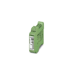
Isolating amplifier with safe electrical isolation and wide-range power supply (24 V ... 230 V AC/DC). DIP switches on the front, over 1600 signal conversions can be set. Standard configuration (IN 0 ... 10 V/OUT 0 ... 20 mA), screw connection, SIL.
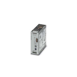
QUINT-PS/24DC/24DC/10 Primary-switched QUINT DC/DC converter for DIN rail mounting with SFB (Selective Fuse Breaking) Technology, input: 24 V DC, output: 24 V DC/10 A
TeSys D contactor - 3P(3 NO) - AC-3 - <= 440 V 40 A - 24 V DC standard coil

TeSys GV motor circuit breaker, 3 poles (3P), 1A/690V, for 3-phase motor applications 0.25kW@400V. It provides a thermal-magnetic protection with a thermal setting range 0.63-1A, magnetic tripping at 13xIn, high breaking capacity Icu 100kA@400V. Connection by screw clamp terminals. Start-stop control by rotary knob guaranteed for 100 000 cycles AC-3. Multi standards certified (IEC, UL, CSA, CCC, EAC, Marine, ATEX).
Main
| Characteristic | Value(s) |
|---|---|
| Range | TeSys Deca |
| product name | TeSys GV2 |
| Product or Component Type | Motor circuit breaker |
| Device short name | GV2P |
| Device Application | Motor protection |
| Trip unit technology | Thermal-magnetic |
Complementary
| Characteristic | Value(s) |
|---|---|
| Poles description | 3P |
| Network type | AC |
| Utilisation category | Category A IEC 60947-2 AC-3 IEC 60947-4-1 AC-3e IEC 60947-4-1 |
| Network frequency | 50/60 Hz IEC 60947-2 |
| Motor power kW | 0.25 kW 400/415 V AC 50/60 Hz 0.55 kW 690 V AC 50/60 Hz |
| Breaking capacity | 100 kA Icu 230/240 V AC 50/60 Hz IEC 60947-2 100 kA Icu 400/415 V AC 50/60 Hz IEC 60947-2 100 kA Icu 440 V AC 50/60 Hz IEC 60947-2 100 kA Icu 500 V AC 50/60 Hz IEC 60947-2 100 kA Icu 690 V AC 50/60 Hz IEC 60947-2 |
| [Ics] rated service short-circuit breaking capacity | 100 % 230/240 V AC 50/60 Hz IEC 60947-2 100 % 400/415 V AC 50/60 Hz IEC 60947-2 100 % 440 V AC 50/60 Hz IEC 60947-2 100 % 500 V AC 50/60 Hz IEC 60947-2 100 % 690 V AC 50/60 Hz IEC 60947-2 |
| Control Type | Rotary handle |
| Line Rated Current | 1 A |
| Thermal protection adjustment range | 0.63â¦1 A IEC 60947-2 |
| Magnetic tripping current | 15.1 A |
| [Ith] conventional free air thermal current | 1 A IEC 60947-2 |
| [Ue] rated operational voltage | 690 V AC 50/60 Hz IEC 60947-2 |
| [Ui] rated insulation voltage | 690 V AC 50/60 Hz IEC 60947-2 |
| [Uimp] rated impulse withstand voltage | 6 kV IEC 60947-2 |
| Phase failure sensitivity | Yes IEC 60947-4-1 |
| Suitability for isolation | Yes IEC 60947-1 |
| Power dissipation per pole | 2.5 W |
| Mechanical durability | 100000 cycles |
| Electrical durability | 100000 cycles AC-3 415 V In 100000 cycles AC-3e 415 V In |
| Rated duty | Uninterrupted IEC 60947-4-1 |
| Connections - terminals | Power circuit screw clamp terminal 2 0.002â¦0.009 in² (1â¦6 mm²)solid Power circuit screw clamp terminal 2 0.002â¦0.009 in² (1.5â¦6 mm²)flexible without cable end Power circuit screw clamp terminal 2 0.002â¦0.006 in² (1â¦4 mm²)flexible with cable end |
| Tightening torque | 15.05 lbf.in (1.7 N.m) screw clamp terminal |
| Fixing mode | 35 mm symmetrical DIN rail clipped Panel screwed with 2 x M4 screws) |
| Mounting position | Horizontal Vertical |
| Width | 1.8 in (45 mm) |
| Height | 3.5 in (89 mm) |
| Depth | 3.8 in (97 mm) |
| color | Dark grey |
TeSys D contactor - 3P(3 NO) - AC-3 - = 440 V 9 A - 24 V AC coil

TeSys Deca contactor, 3 poles (3NO), for motor control applications up to 9A/690V AC-3/3e (4kW@400V). They can be used to create motor starters for almost any type of application. It provides a 24V DC coil with transient suppressor module, 1NO+1NC built-in auxiliary contacts (NC mirror certified), connection by screw clamp terminals. For operating rates until 3600 cycles/hour and environments until 60°C, it procures high reliability and durability to demanding applications. Compact (45mm width), DIN-rail mounting or screw fixing. Contactor is rated for 20HP at 200-208VAC, 25HP at 240VAC, 60HP at 480VAC and 60HP at 600VAC three phase. Multi standards certified (IEC, UL, CSA, CCC, EAC, Marine). When used with a 480VAC up to 35A circuit breaker, this contactor can have a SCCR up to 85kA. When used with up to a 600VAC 25A Class J or CC fuse, this contactor can have a SCCR up to 100kA. Contactor is supplied with a 24 VDC coil with transient suppressor module. Contactor has one normally open and one normally closed auxiliary contact built-in as standard. The NC contact is mirror certified. Screw clamp terminals are used for load and auxiliary connections. An extensive line of accessories makes it easy to meet the requirements of most applications. The contactor is 3.15 inches tall, 1.77 inches wide and 3.39 inches deep. It weighs 0.71 lbs. Contactor is certified to UL, CSA, IEC, CCC, EAC and Marine standards.
Main
| Characteristic | Value(s) |
|---|---|
| Range of Product | TeSys Deca |
| Product or Component Type | Contactor |
| Device short name | LC1D |
| Contactor application | Motor control Resistive load |
| Utilisation category | AC-4 AC-1 AC-3 AC-3e |
| Poles description | 3P |
| [Ue] rated operational voltage | Power circuit <= 690 V AC 25...400 Hz Power circuit <= 300 V DC |
| [Ie] rated operational current | 9 A (at <140 °F (60 °C)) at <= 440 V AC AC-3 for power circuit 25 A (at <140 °F (60 °C)) at <= 440 V AC AC-1 for power circuit 9 A (at <140 °F (60 °C)) at <= 440 V AC AC-3e for power circuit |
| [Uc] control circuit voltage | 24 V DC |
Complementary
| Characteristic | Value(s) |
|---|---|
| Motor power kW | 2.2 kW at 220...230 V AC 50/60 Hz (AC-3) 4 kW at 380...400 V AC 50/60 Hz (AC-3) 4 kW at 415...440 V AC 50/60 Hz (AC-3) 5.5 kW at 500 V AC 50/60 Hz (AC-3) 5.5 kW at 660...690 V AC 50/60 Hz (AC-3) 2.2 kW at 400 V AC 50/60 Hz (AC-4) 2.2 kW at 220...230 V AC 50/60 Hz (AC-3e) 4 kW at 380...400 V AC 50/60 Hz (AC-3e) 4 kW at 415...440 V AC 50/60 Hz (AC-3e) 5.5 kW at 500 V AC 50/60 Hz (AC-3e) 5.5 kW at 660...690 V AC 50/60 Hz (AC-3e) |
| Maximum Horse Power Rating | 1 hp at 230/240 V AC 50/60 Hz for 1 phase motors 2 hp at 200/208 V AC 50/60 Hz for 3 phase motors 2 hp at 230/240 V AC 50/60 Hz for 3 phase motors 5 hp at 460/480 V AC 50/60 Hz for 3 phase motors 7.5 hp at 575/600 V AC 50/60 Hz for 3 phase motors 0.33 hp at 115 V AC 50/60 Hz for 1 phase motors |
| Compatibility code | LC1D |
| Pole contact composition | 3 NO |
| Protective cover | With |
| [Ith] conventional free air thermal current | 25 A (at 140 °F (60 °C)) for power circuit 10 A (at 140 °F (60 °C)) for signalling circuit |
| Irms rated making capacity | 250 A at 440 V for power circuit conforming to IEC 60947 140 A AC for signalling circuit conforming to IEC 60947-5-1 250 A DC for signalling circuit conforming to IEC 60947-5-1 |
| Rated breaking capacity | 250 A at 440 V for power circuit conforming to IEC 60947 |
| [Icw] rated short-time withstand current | 105 A 104 °F (40 °C) - 10 s for power circuit 210 A 104 °F (40 °C) - 1 s for power circuit 30 A 104 °F (40 °C) - 10 min for power circuit 61 A 104 °F (40 °C) - 1 min for power circuit 100 A - 1 s for signalling circuit 120 A - 500 ms for signalling circuit 140 A - 100 ms for signalling circuit |
| Associated fuse rating | 10 A gG for signalling circuit conforming to IEC 60947-5-1 25 A gG at <= 690 V coordination type 1 for power circuit 20 A gG at <= 690 V coordination type 2 for power circuit |
| Average impedance | 2.5 mOhm - Ith 25 A 50 Hz for power circuit |
| Power dissipation per pole | 1.56 W AC-1 0.2 W AC-3 0.2 W AC-3e |
| [Ui] rated insulation voltage | Power circuit 690 V IEC 60947-4-1 Power circuit 600 V CSA Power circuit 600 V UL Signalling circuit 690 V IEC 60947-1 Signalling circuit 600 V CSA Signalling circuit 600 V UL |
| Overvoltage category | III |
| pollution degree | 3 |
| [Uimp] rated impulse withstand voltage | 6 kV IEC 60947 |
| Safety reliability level | B10d = 1369863 cycles contactor with nominal load EN/ISO 13849-1 B10d = 20000000 cycles contactor with mechanical load EN/ISO 13849-1 |
| Mechanical durability | 30 Mcycles |
| Electrical durability | 0.6 Mcycles 25 A AC-1 <= 440 V 2 Mcycles 9 A AC-3 <= 440 V 2 Mcycles 9 A AC-3e <= 440 V |
| Control circuit type | DC standard |
| Coil technology | Built-in bidirectional peak limiting diode suppressor |
| Control circuit voltage limits | 0.1...0.25 Uc (-40â¦158 °F (-40â¦70 °C)):drop-out DC 0.7...1.25 Uc (-40â¦140 °F (-40â¦60 °C)):operational DC 1...1.25 Uc (140â¦158 °F (60â¦70 °C)):operational DC |
| Inrush power in W | 5.4 W 68 °F (20 °C)) |
| Hold-in power consumption in W | 5.4 W 68 °F (20 °C) |
| Operating time | 63 ±15 % ms closing 20 ±20 % ms opening |
| Time constant | 28 ms |
| Maximum operating rate | 3600 cyc/h at 60 °C |
| Connections - terminals | Power circuit: screw clamp terminals 1 0.002â¦0.006 in² (1â¦4 mm²) - cable stiffness: flexible without cable end Power circuit: screw clamp terminals 2 0.002â¦0.006 in² (1â¦4 mm²) - cable stiffness: flexible without cable end Power circuit: screw clamp terminals 1 0.002â¦0.006 in² (1â¦4 mm²) - cable stiffness: flexible with cable end Power circuit: screw clamp terminals 2 0.002â¦0.004 in² (1â¦2.5 mm²) - cable stiffness: flexible with cable end Power circuit: screw clamp terminals 1 0.002â¦0.006 in² (1â¦4 mm²) - cable stiffness: solid without cable end Power circuit: screw clamp terminals 2 0.002â¦0.006 in² (1â¦4 mm²) - cable stiffness: solid without cable end Control circuit: screw clamp terminals 1 0.002â¦0.006 in² (1â¦4 mm²) - cable stiffness: flexible without cable end Control circuit: screw clamp terminals 2 0.002â¦0.006 in² (1â¦4 mm²) - cable stiffness: flexible without cable end Control circuit: screw clamp terminals 1 0.002â¦0.006 in² (1â¦4 mm²) - cable stiffness: flexible with cable end Control circuit: screw clamp terminals 2 0.002â¦0.004 in² (1â¦2.5 mm²) - cable stiffness: flexible with cable end Control circuit: screw clamp terminals 1 0.002â¦0.006 in² (1â¦4 mm²) - cable stiffness: solid without cable end Control circuit: screw clamp terminals 2 0.002â¦0.006 in² (1â¦4 mm²) - cable stiffness: solid without cable end |
| Tightening torque | Power circuit 15.05 lbf.in (1.7 N.m) screw clamp terminals flat à 6 mm Power circuit 15.05 lbf.in (1.7 N.m) screw clamp terminals Philips No 2 Control circuit 15.05 lbf.in (1.7 N.m) screw clamp terminals flat à 6 mm Control circuit 15.05 lbf.in (1.7 N.m) screw clamp terminals Philips No 2 Control circuit 15.05 lbf.in (1.7 N.m) screw clamp terminals pozidriv No 2 Power circuit 15.05 lbf.in (1.7 N.m) screw clamp terminals pozidriv No 2 |
| Auxiliary contact composition | 1 NO + 1 NC |
| Auxiliary contacts type | Mechanically linked 1 NO + 1 NC IEC 60947-5-1 Mirror contact 1 NC IEC 60947-4-1 |
| Signalling circuit frequency | 25...400 Hz |
| Minimum switching voltage | 17 V for signalling circuit |
| Minimum switching current | 5 mA for signalling circuit |
| Insulation resistance | > 10 MOhm for signalling circuit |
| Non-overlap time | 1.5 ms on de-energisation between NC and NO contact 1.5 ms on energisation between NC and NO contact |
| Mounting Support | Plate Rail |

Motor circuit breaker, TeSys GV2, 3P, 1.6-2.5 A, thermal magnetic, screw clamp terminals