
 1 year warranty

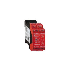
module XPS-MP - 2 independent functions - 24 V DC
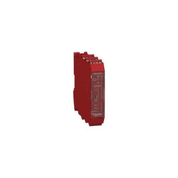
This product is part of preventa XPCMC configurable safety controller range. It is a configurable safety controller. It is supplied with 24 V DC. It has 32 safety inputs. It conforms to Category 4 maximum conforming to EN 954-1/EN/ISO 13849-1, PLE safety level conforming to EN/ISO 13849-1 and SIL 3 level conforming to IEC 61508. It embeds 1 RJ45 port for serial link communication with Modbus protocol. Transmission rate are 1200/2400/4800/9600 and 19200bps, and another SUB-D 9-pin male port for CANopen communication. Transmission rate are 20/50/125 and 250kbps. This product measures 153mm depth, 151.5mm height, and 74mm width. It weighs 0.84kg. This safety controller is designed for monitoring multiple safety functions such as emergency stop, guard monitoring, perimeter guarding, position monitoring, speed monitoring and enabling movement. This product is certified by CSA, UL and TÃV. It conforms to EN 954-1/EN/ISO 13849-1, EN/IEC 61496-1, IEC 61508, EN/IEC 60204-1, EN 1760-1/ISO 13856-1, EN 574/ISO 13851 and EN/IEC 60947-5-1 standards. The Safety controller XPSMC is configurable and addressable using software XPSMCWIN running on a PC and using a USB/RJ45 cable type TCSMCNAM3M002P to connect to the safety controller. It installs with a mounting plate for mounting on rail. Preventa XPSMC configurable safety controller is designed to provide a solution for safety applications requiring conformity to Performance Level PL e/Category 4 EN ISO 13849-1 and SIL3 EN/IEC 61508. The configurable safety controller consists of 6 variants with 16 or 32 digital inputs and 8 digital outputs and communication possibilities of Modbus RTL Serial, Profibus DP and CANopen.
Main
| Characteristic | Value(s) |
|---|---|
| Range of Product | Preventa Safety automation |
| Product or Component Type | Configurable safety controller |
| Safety module name | XPSMC |
| Safety use category | Category 4 maximum EN 954-1/EN/ISO 13849-1 PLE maximum ISO 13849-1 SIL 3 maximum IEC 61508 |
| Type of start | Configurable |
| Standards | IEC 60947-5-1 EN 574/ISO 13851 EN 1760-1/ISO 13856-1 IEC 61496-1 IEC 61508 EN 954-1/EN/ISO 13849-1 IEC 60204-1 |
| Product Certifications | UL TÃV CSA |
| [Us] Rated Supply Voltage | 24 V DC - 20...20 % |
| Number of inputs | 32 |
| Communication port protocol | CANopen 1 SUB-D 9-pin male, serial link 20 kbps, 50 kbps, 125 kbps, 250 kbps, 500 kbps, 800 kbps or 1 Mbps Modbus 1 RJ45, serial link 1200 bps, 2400 bps, 4800 bps, 9600 bps or 19200 bps |
| Safety level | Can reach PL e/category 4 EN 954-1/EN/ISO 13849-1 Can reach SIL 3 IEC 61508 |
Complementary
| Characteristic | Value(s) |
|---|---|
| Function of module | Dynamic monitoring of hydraulic valves on linear presses Eccentric press Emergency stop monitoring, with or without time delay, 1 or 2-channel wiring Enabling switch monitoring, 2 or 3 contacts Foot switch monitoring Guard monitoring for injection presses and blowing machines Guard monitoring with 1 or 2 limit switches Hydraulic press Magnetic switch monitoring category 4 EN/IEC 61496 Monitoring safety stop at top dead centre on eccentric press category 3 EN 574/ISO 13851 Muting function of light curtains Position selector Safety mat monitoring Safety time delays Shaft/chain breaking monitor Zero speed detection Light curtain monitoring category 4 IEC 61496 Two-hand control category 3 EN 574/ISO 13851 |
| Synchronisation time between inputs | Depending on configuration selected |
| Power Consumption in W | 12 W |
| Input protection type | External fuse 16 A |
| [Uc] control circuit voltage | 28.8 V |
| Maximum line resistance | 100 Ohm <6561.7 ft (2000 m) |
| Output type | 2 relays, 2 NO contacts (4 NO total) Solid state, 6, volt-free |
| Breaking capacity | 180 VA holding AC-15 C300 relay output 1800 VA inrush AC-15 C300 relay output |
| Breaking capacity | 2 A 24 V static output circuit 1.5 A 24 V DC-13)50 ms relay output |
| Output thermal current | 4 A for both outputs simultaneously 6 A for 1 output and 2 A for the other relay output |
| [Ith] conventional free air thermal current | 16 A relay output 6.5 A static output circuit |
| Associated fuse rating | 16 A gL power supply 4 A gL relay output 6 A fast blow relay output |
| Minimum output current | 10 mA relay output |
| Minimum output voltage | 17 V relay output |
| Response Time | Configurable : 20 ms or 30 ms with software XPSMCWIN |
| [Ui] rated insulation voltage | 300 V 2)IEC 60647-5-1, DIN VDE 0110 part 1 |
| [Uimp] rated impulse withstand voltage | 4 kV III IEC 60647-5-1, DIN VDE 0110 part 1 |
| Method of access | Slave |
| Exchange size | 14 words |
| Number of addresses | 1â¦127 CANopen 1â¦247 Modbus |
| Parity | Even Modbus No Modbus Odd Modbus |
| Data format | 1 start bit/8 data bits 1 stop bit even or odd 2 stop bits without parity RTU (Remote Terminal Unit) mode |
| Supported modbus function | 01 8-bit output data/32-bit input data 02 32-bit input data/8-bit output data 03 information and errors |
| Local signalling | 48 LEDs |
| Mounting Support | Mounting plate |
| Depth | 6.02 in (153 mm) |
| Height | 6.0 in (151.5 mm) |
| Width | 2.9 in (74 mm) |
| Product Weight | 1.85 lb(US) (0.84 kg) |

Main
| Characteristic | Value(s) |
|---|---|
| Range of Product | Preventa Safety automation |
| Product or Component Type | Preventa safety PLC compact |
| Safety module name | XPSMF40 |
| Safety module application | F use with numerous machine safety functions and for the protection of personel |
| Safety use category | Category 4 maximum EN 954-1 Performance level e EN/ISO 13849-1 SIL 3 EN/IEC 61508 |
| Structure type | 10BASE-T/100BASE-TX, safe Ethernet |
Complementary
| Characteristic | Value(s) |
|---|---|
| Function of module | Monitoring safety actuators discrete output Monitoring safety detection discrete input Monitoring safety dialogue discrete input Monitoring safety dialogue discrete output Monitoring short-circuit and line break line control outputs |
| [Us] Rated Supply Voltage | 24 V DC - 15...20 % |
| Supply | SELV or PELV EN/IEC 60950 |
| No load current | 0.5 A |
| Protection Type | 10 A internal fuse |
| Clock | With, supplied by backup capacitor for 1 week following loss of supply |
| Response Time | Depending on size of application |
| Memory description | User logic 250 kB application User logic 250 kB data |
| Group of channels | 2 groups of 4 line control outputs |
| Discrete I/O number | 24 configurable |
| Maximum discrete input number | 24 not isolated |
| Voltage state 0 guaranteed | <= 24 V discrete input |
| Voltage state 1 guaranteed | 24...30 V discrete input |
| Current state 0 guaranteed | <= 1.5 mA discrete input) |
| Current state 1 guaranteed | 3.5...4.5 mA discrete input) |
| Discrete input voltage | 20 V |
| Discrete input current | 100 mA |
| Maximum input resistance | 7 kOhm |
| Input overvoltage protection | -10â¦35 V discrete input |
| Maximum discrete output number | 24 not isolated |
| Discrete output voltage | 24 V DC |
| Output voltage tolerance | +/- 2% |
| Discrete output current | 1 A 140 °F (60 °C) channels 4, 8, 12, 16, 20 and 24) 2 A 122 °F (50 °C) channels 4, 8, 12, 16, 20 and 24) 0.5 A 140 °F (60 °C) channels 1 to 3, 5 to 7, 9 to 11,13 to 15, 17 to 19, 21 to 23) <= 7 A all channels) |
| Minimum load | 2 mA per discrete output |
| Maximum leakage current | 1 mA 2 V at state 0 discrete output |
| Overload protection | Shutdown of outputs concerned with cyclic reconnection |
| Output voltage | 20 V line control outputs |
| Nominal output current | 60 mA line control outputs |
| Communication port protocol | Safe Ethernet 2 RJ45 100 Mbps, 10 Mbps dual twisted pair cable, category 5D or better Profibus 1 SUB-D 9-pin female, RS485 shielded dual twisted pair cable |
| Exchange mode | Half duplex, full duplex, autonegotiation safe Ethernet |
| Method of access | Slave V0 Profibus |
| Operating distance | <= 300 m between station discrete input <= 300 m between station discrete output |
| Number of terminal blocks | 1 power supply 2 line control outputs 6 discrete input/output circuit 8 line control outputs |
| Connections - terminals | Discrete input/output circuit captive spring terminals, 1 x 0.5 mm² AWG 20) flexible with cable end Line control outputs captive spring terminals, 1 x 0.5 mm² AWG 20) flexible with cable end Discrete input/output circuit captive screw clamp terminals, 1 x 0.14...1 x 1.5 mm² AWG 25...AWG 15) solid without cable end Line control outputs captive screw clamp terminals, 1 x 0.14...1 x 1.5 mm² AWG 25...AWG 15) solid without cable end Discrete input/output circuit captive screw clamp terminals, 1 x 0.14...1 x 1.5 mm² AWG 28...AWG 16) flexible without cable end Line control outputs captive screw clamp terminals, 1 x 0.14...1 x 1.5 mm² AWG 28...AWG 16) flexible without cable end Power supply captive screw clamp terminals, 1 x 0.2...1 x 2.5 mm² AWG 24...AWG 12) flexible without cable end Power supply captive screw clamp terminals, 1 x 0.2...1 x 2.5 mm² AWG 24...AWG 12) solid without cable end Discrete input/output circuit captive screw clamp terminals, 1 x 0.25...1 x 0.5 mm² AWG 23...AWG 20) flexible with cable end Line control outputs captive screw clamp terminals, 1 x 0.25...1 x 0.5 mm² AWG 23...AWG 20) flexible with cable end Discrete input/output circuit captive screw clamp terminals, 1 x 0.25...1 x 1.5 mm² AWG 23...AWG 15) flexible without cable end Line control outputs captive screw clamp terminals, 1 x 0.25...1 x 1.5 mm² AWG 23...AWG 15) flexible without cable end Power supply captive screw clamp terminals, 1 x 0.25...1 x 2.5 mm² AWG 23...AWG 14) flexible with cable end Power supply captive screw clamp terminals, 1 x 0.25...1 x 2.5 mm² AWG 23...AWG 14) flexible without cable end Discrete input/output circuit captive spring terminals, 1 x 0.14...1 x 1.5 mm² AWG 26...AWG 16) solid without cable end Line control outputs captive spring terminals, 1 x 0.14...1 x 1.5 mm² AWG 26...AWG 16) solid without cable end Discrete input/output circuit captive spring terminals, 1 x 0.14...1 x 1.5 mm² AWG 26...AWG 17) flexible without cable end Line control outputs captive spring terminals, 1 x 0.14...1 x 1.5 mm² AWG 26...AWG 17) flexible without cable end Power supply captive spring terminals, 1 x 0.2...1 x 2.5 mm² AWG 24...AWG 12) flexible without cable end Power supply captive spring terminals, 1 x 0.2...1 x 2.5 mm² AWG 24...AWG 12) solid without cable end Discrete input/output circuit captive spring terminals, 1 x 0.25...1 x 0.34 mm² AWG 22) flexible without cable end Line control outputs captive spring terminals, 1 x 0.25...1 x 0.34 mm² AWG 22) flexible without cable end Power supply captive spring terminals, 1 x 0.25...1 x 2.5 mm² AWG 23...AWG 12) flexible with cable end Power supply captive spring terminals, 1 x 0.25...1 x 2.5 mm² AWG 23...AWG 12) flexible without cable end |
| Tightening torque | Discrete input/output circuit 1.95â¦2.21 lbf.in (0.22â¦0.25 N.m) captive screw clamp terminals Line control outputs 1.95â¦2.21 lbf.in (0.22â¦0.25 N.m) captive screw clamp terminals Power supply 4.4 lbf.in (0.5 N.m) captive screw clamp terminals |
| Wire stripping length | 0.4 in (10 mm) power supply captive screw clamp terminals 0.4 in (9 mm) discrete input/output circuit captive screw clamp terminals 0.4 in (9 mm) discrete input/output circuit captive spring terminals 0.4 in (9 mm) line control outputs captive screw clamp terminals 0.4 in (9 mm) line control outputs captive spring terminals 0.4 in (9 mm) power supply captive spring terminals |
| Current consumption | 8 A 24 V DC on power supply |
| Mounting Support | 35 mm symmetrical DIN rail |
| Depth | 6.02 in (153 mm) |
| Height | 6.0 in (151.5 mm) |
| Width | 2.9 in (74 mm) |
| Product Weight | 2.2 lb(US) (1 kg) |
Main
| Characteristic | Value(s) |
|---|---|
| Range of Product | Preventa Safety automation |
| Product or Component Type | Preventa safety PLC compact |
| Safety module name | XPSMF40 |
| Safety module application | F use with numerous machine safety functions and for the protection of personel |
| Safety use category | Category 4 maximum EN 954-1 Performance level e EN/ISO 13849-1 SIL 3 EN/IEC 61508 |
| Structure type | 10BASE-T/100BASE-TX, Modbus TCP/IP 10BASE-T/100BASE-TX, safe Ethernet |
Complementary
| Characteristic | Value(s) |
|---|---|
| Function of module | Monitoring safety actuators discrete output Monitoring safety detection discrete input Monitoring safety dialogue discrete input Monitoring safety dialogue discrete output Monitoring short-circuit and line break line control outputs |
| [Us] Rated Supply Voltage | 24 V DC - 15...20 % |
| Supply | SELV or PELV EN/IEC 60950 |
| No load current | 0.5 A |
| Protection Type | 10 A internal fuse |
| Clock | With, supplied by backup capacitor for 1 week following loss of supply |
| Response Time | Depending on size of application |
| Memory description | User logic 250 kB application User logic 250 kB data |
| Group of channels | 2 groups of 4 line control outputs |
| Discrete I/O number | 24 configurable |
| Maximum discrete input number | 24 not isolated |
| Voltage state 0 guaranteed | <= 24 V discrete input |
| Voltage state 1 guaranteed | 24...30 V discrete input |
| Current state 0 guaranteed | <= 1.5 mA discrete input) |
| Current state 1 guaranteed | 3.5...4.5 mA discrete input) |
| Discrete input voltage | 20 V |
| Discrete input current | 100 mA |
| Maximum input resistance | 7 kOhm |
| Input overvoltage protection | -10â¦35 V discrete input |
| Maximum discrete output number | 24 not isolated |
| Discrete output voltage | 24 V DC |
| Output voltage tolerance | +/- 2% |
| Discrete output current | 1 A 140 °F (60 °C) channels 4, 8, 12, 16, 20 and 24) 2 A 122 °F (50 °C) channels 4, 8, 12, 16, 20 and 24) 0.5 A 140 °F (60 °C) channels 1 to 3, 5 to 7, 9 to 11,13 to 15, 17 to 19, 21 to 23) <= 7 A all channels) |
| Minimum load | 2 mA per discrete output |
| Maximum leakage current | 1 mA 2 V at state 0 discrete output |
| Overload protection | Shutdown of outputs concerned with cyclic reconnection |
| Output voltage | 20 V line control outputs |
| Nominal output current | 60 mA line control outputs |
| Communication port protocol | Safe Ethernet 2 RJ45 100 Mbps, 10 Mbps dual twisted pair cable, category 5D or better Modbus TCP/IP 2 RJ45 100 Mbps, 10 Mbps dual twisted pair cable, category 5D or better Modbus RTU 1 RJ45, RS485 shielded dual twisted pair cable |
| Exchange mode | Half duplex, full duplex, autonegotiation Modbus TCP/IP Half duplex, full duplex, autonegotiation safe Ethernet |
| Method of access | Slave Modbus TCP/IP Slave V0 Modbus serial |
| Number of addresses | 122 Modbus serial |
| Concept | Transparent Ready, Modbus TCP/IP |
| Web server | Class A10, Modbus TCP/IP |
| Web services | Modbus identification request, Modbus TCP/IP Modbus TCP/IP messaging (reading/writing of data words), Modbus TCP/IP Modbus TCP/IP server, Modbus TCP/IP Standard 502, Modbus TCP/IP |
| Maximum number of connections | 1 to 20, Modbus TCP/IP |
| Operating distance | <= 300 m between station discrete input <= 300 m between station discrete output |
| Number of terminal blocks | 1 power supply 2 line control outputs 6 discrete input/output circuit 8 line control outputs |
| Connections - terminals | Discrete input/output circuit captive spring terminals, 1 x 0.5 mm² AWG 20) flexible with cable end Line control outputs captive spring terminals, 1 x 0.5 mm² AWG 20) flexible with cable end Discrete input/output circuit captive screw clamp terminals, 1 x 0.14...1 x 1.5 mm² AWG 25...AWG 15) solid without cable end Line control outputs captive screw clamp terminals, 1 x 0.14...1 x 1.5 mm² AWG 25...AWG 15) solid without cable end Discrete input/output circuit captive screw clamp terminals, 1 x 0.14...1 x 1.5 mm² AWG 28...AWG 16) flexible without cable end Line control outputs captive screw clamp terminals, 1 x 0.14...1 x 1.5 mm² AWG 28...AWG 16) flexible without cable end Power supply captive screw clamp terminals, 1 x 0.2...1 x 2.5 mm² AWG 24...AWG 12) flexible without cable end Power supply captive screw clamp terminals, 1 x 0.2...1 x 2.5 mm² AWG 24...AWG 12) solid without cable end Discrete input/output circuit captive screw clamp terminals, 1 x 0.25...1 x 0.5 mm² AWG 23...AWG 20) flexible with cable end Line control outputs captive screw clamp terminals, 1 x 0.25...1 x 0.5 mm² AWG 23...AWG 20) flexible with cable end Discrete input/output circuit captive screw clamp terminals, 1 x 0.25...1 x 1.5 mm² AWG 23...AWG 15) flexible without cable end Line control outputs captive screw clamp terminals, 1 x 0.25...1 x 1.5 mm² AWG 23...AWG 15) flexible without cable end Power supply captive screw clamp terminals, 1 x 0.25...1 x 2.5 mm² AWG 23...AWG 14) flexible with cable end Power supply captive screw clamp terminals, 1 x 0.25...1 x 2.5 mm² AWG 23...AWG 14) flexible without cable end Discrete input/output circuit captive spring terminals, 1 x 0.14...1 x 1.5 mm² AWG 26...AWG 16) solid without cable end Line control outputs captive spring terminals, 1 x 0.14...1 x 1.5 mm² AWG 26...AWG 16) solid without cable end Discrete input/output circuit captive spring terminals, 1 x 0.14...1 x 1.5 mm² AWG 26...AWG 17) flexible without cable end Line control outputs captive spring terminals, 1 x 0.14...1 x 1.5 mm² AWG 26...AWG 17) flexible without cable end Power supply captive spring terminals, 1 x 0.2...1 x 2.5 mm² AWG 24...AWG 12) flexible without cable end Power supply captive spring terminals, 1 x 0.2...1 x 2.5 mm² AWG 24...AWG 12) solid without cable end Discrete input/output circuit captive spring terminals, 1 x 0.25...1 x 0.34 mm² AWG 22) flexible without cable end Line control outputs captive spring terminals, 1 x 0.25...1 x 0.34 mm² AWG 22) flexible without cable end Power supply captive spring terminals, 1 x 0.25...1 x 2.5 mm² AWG 23...AWG 12) flexible with cable end Power supply captive spring terminals, 1 x 0.25...1 x 2.5 mm² AWG 23...AWG 12) flexible without cable end |
| Tightening torque | Discrete input/output circuit 1.95â¦2.21 lbf.in (0.22â¦0.25 N.m) captive screw clamp terminals Line control outputs 1.95â¦2.21 lbf.in (0.22â¦0.25 N.m) captive screw clamp terminals Power supply 4.4 lbf.in (0.5 N.m) captive screw clamp terminals |
| Wire stripping length | 0.4 in (10 mm) power supply captive screw clamp terminals 0.4 in (9 mm) discrete input/output circuit captive screw clamp terminals 0.4 in (9 mm) discrete input/output circuit captive spring terminals 0.4 in (9 mm) line control outputs captive screw clamp terminals 0.4 in (9 mm) line control outputs captive spring terminals 0.4 in (9 mm) power supply captive spring terminals |
| Current consumption | 8 A 24 V DC on power supply |
| Mounting Support | 35 mm symmetrical DIN rail |
| Depth | 6.02 in (153 mm) |
| Height | 6.0 in (151.5 mm) |
| Width | 2.9 in (74 mm) |
| Product Weight | 2.2 lb(US) (1 kg) |

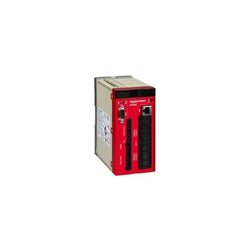
safety controller XPS-MC - 24 V DC - 16 input - 30 LEDs signalling
Main
| Characteristic | Value(s) |
|---|---|
| Range of Product | Preventa Safety automation |
| Product or Component Type | Preventa safety PLC compact |
| Safety module name | XPSMF35 |
| Safety module application | For numerous machine safety functions and for the protection of personnel |
| Safety use category | Category 4 EN 954-1/ISO 13849-1 SIL 3 IEC 61508 |
| Structure type | 10BASE-T/100BASE-TX, Modbus TCP/IP 10BASE-T/100BASE-TX, safe Ethernet |
Complementary
| Characteristic | Value(s) |
|---|---|
| Function of module | Closed circuit scanning of input channels analogue input circuit Measuring 0 to 20 mA currents using shunt analogue input circuit Monitoring safety actuators discrete output Monitoring safety detection discrete input Monitoring safety dialogue discrete input Monitoring safety dialogue discrete output Single-pole measuring of 0 to 10 V voltages analogue input circuit |
| [Us] Rated Supply Voltage | 24 V DC - 15...20 % |
| No load current | 0.75 A |
| Protection Type | Internal fuse |
| Clock | With, supplied by backup capacitor for 1 week following loss of supply |
| Response Time | Depending on size of application |
| Memory description | User logic 250 kB application User logic 250 kB data |
| Discrete input number | 24 not isolated |
| Voltage state 0 guaranteed | <= 5 V discrete input |
| Voltage state 1 guaranteed | 24...30 V discrete input |
| Current state 0 guaranteed | 1...1.5 mA discrete input) |
| Current state 1 guaranteed | 3.5...4.5 mA discrete input) |
| Discrete input voltage | 20 V |
| Discrete input current | 100 mA |
| Input protection type | Protected against short-circuit to earth Protected against short-circuit |
| Input overvoltage protection | 500 V discrete input IEC 61000-4-5 -4â¦15 V analogue input circuit |
| Discrete output number | 8 |
| Discrete output voltage | 24 V DC |
| Output voltage tolerance | +/- 2% |
| Discrete output current | 1 A 140 °F (60 °C) channels 4 and 8) 2 A 122 °F (50 °C) channels 4 and 8) 0.5 A 140 °F (60 °C) channels 1 to 3 and 5 to 7) <= 7 mA all channels) |
| Minimum load | 2 mA per discrete output |
| Maximum leakage current | 1 mA 2 V at state 0 discrete output |
| Overload protection | Shutdown of outputs concerned with cyclic reconnection |
| Analogue input number | 8 |
| Analogue Output Type | Not isolated |
| External resistance | 250 Ohm analogue input circuit 500 Ohm analogue input circuit |
| Analogue input range | 0...20 mA 500 Ohm 0...10 V |
| Input voltage limits | 0.1...11.5 V analogue input circuit |
| Input current limits | 0.4â¦23 mA 500 Ohm analogue input circuit |
| Analogue input resolution | 12 bits |
| Safety accuracy | +/- 2 % analogue input circuit |
| Maximum internal input resistance | 500 MOhm for signal source analogue input circuit 1 kOhm analogue input circuit 3.7 Ohm counting inputs |
| Counting input number | 2 |
| Counting input type | Non isolated |
| Counting frequency | 100 kHz |
| Operating threshold | 0...0.05 V, 5 V low counting inputs 13...33 V, 24 V high counting inputs -3...5 V, 24 V low counting inputs 4...6 V, 5 V high counting inputs |
| Counter inputs resolution | 24 bits |
| DV/dt | 1 V/µs counting inputs |
| Communication port protocol | Modbus TCP/IP 4 RJ45 100 Mbps, 10 Mbps dual twisted pair cable, category 5D or better Safe Ethernet 4 RJ45 100 Mbps, 10 Mbps dual twisted pair cable, category 5D or better Modbus RTU 1 SUB-D 9-pin female, RS485 shielded dual twisted pair cable Profibus 1 SUB-D 9-pin female, RS485 shielded dual twisted pair cable |
| Exchange mode | Half duplex, full duplex, autonegotiation Modbus TCP/IP Half duplex, full duplex, autonegotiation safe Ethernet |
| Method of access | Slave Modbus Slave Modbus TCP/IP Slave Profibus |
| Number of addresses | 122 Modbus |
| Concept | Transparent Ready, Modbus TCP/IP |
| Web server | Class A10, Modbus TCP/IP |
| Web services | Modbus identification request, Modbus TCP/IP Modbus TCP/IP messaging (reading/writing of data words), Modbus TCP/IP Modbus TCP/IP server, Modbus TCP/IP Standard 502, Modbus TCP/IP |
| Operating distance | <= 500 m between station) shielded dual twisted pair cable counting inputs <= 100 m between station) discrete input <= 100 m between station) discrete output <= 300 m between station) analogue input circuit |
| Number of terminal blocks | 1 counting inputs 1 power supply 2 discrete output 4 analogue input circuit 5 discrete input |
| Connections - terminals | Analogue input circuit captive screw clamp terminals, 2 x 0.5 mm² AWG 20) flexible with cable end Counting inputs captive screw clamp terminals, 2 x 0.5 mm² AWG 20) flexible with cable end Discrete input/output circuit captive screw clamp terminals, 2 x 0.5 mm² AWG 20) flexible with cable end Discrete input/output circuit captive screw clamp terminals, 1 x 0.14...1 x 1.5 mm² AWG 28...AWG 16) flexible without cable end Discrete input/output circuit captive screw clamp terminals, 1 x 0.14...1 x 1.5 mm² AWG 28...AWG 16) solid without cable end Power supply captive screw clamp terminals, 1 x 0.2...1 x 2.5 mm² AWG 24...AWG 12) flexible without cable end Power supply captive screw clamp terminals, 1 x 0.2...1 x 2.5 mm² AWG 24...AWG 12) solid without cable end Discrete input/output circuit captive screw clamp terminals, 1 x 0.25...1 x 0.5 mm² AWG 22...AWG 20) flexible with cable end Discrete input/output circuit captive screw clamp terminals, 1 x 0.25...1 x 1.5 mm² AWG 22...AWG 16) flexible without cable end Power supply captive screw clamp terminals, 1 x 0.25...1 x 2.5 mm² AWG 22...AWG 16) flexible with cable end Power supply captive screw clamp terminals, 1 x 0.25...1 x 2.5 mm² AWG 22...AWG 16) flexible without cable end Discrete input/output circuit captive screw clamp terminals, 2 x 0.14...2 x 0.5 mm² AWG 28...AWG 20) solid without cable end Discrete input/output circuit captive screw clamp terminals, 2 x 0.14...2 x 0.75 mm² AWG 28...AWG 18) flexible without cable end Power supply captive screw clamp terminals, 2 x 0.2...2 x 1.5 mm² AWG 24...AWG 12) flexible without cable end Power supply captive screw clamp terminals, 2 x 0.2...2 x 1.5 mm² AWG 24...AWG 12) solid without cable end Discrete input/output circuit captive screw clamp terminals, 2 x 0.25...2 x 0.34 mm² AWG 22) flexible without cable end Power supply captive screw clamp terminals, 2 x 0.25...2 x 1 mm² AWG 22...AWG 18) flexible without cable end Power supply captive screw clamp terminals, 2 x 0.5...2 x 1.5 mm² AWG 22...AWG 16) flexible with cable end Analogue input circuit captive screw clamp terminals, 1 x 0.14...1 x 1.5 mm² AWG 28...AWG 16) flexible without cable end Counting inputs captive screw clamp terminals, 1 x 0.14...1 x 1.5 mm² AWG 28...AWG 16) flexible without cable end Analogue input circuit captive screw clamp terminals, 1 x 0.14...1 x 1.5 mm² AWG 28...AWG 16) solid without cable end Counting inputs captive screw clamp terminals, 1 x 0.14...1 x 1.5 mm² AWG 28...AWG 16) solid without cable end Analogue input circuit captive screw clamp terminals, 1 x 0.25...1 x 0.5 mm² AWG 22...AWG 20) flexible with cable end Counting inputs captive screw clamp terminals, 1 x 0.25...1 x 0.5 mm² AWG 22...AWG 20) flexible with cable end Analogue input circuit captive screw clamp terminals, 1 x 0.25...1 x 1.5 mm² AWG 22...AWG 16) flexible without cable end Counting inputs captive screw clamp terminals, 1 x 0.25...1 x 1.5 mm² AWG 22...AWG 16) flexible without cable end Analogue input circuit captive screw clamp terminals, 2 x 0.14...2 x 0.5 mm² AWG 28...AWG 20) solid without cable end Counting inputs captive screw clamp terminals, 2 x 0.14...2 x 0.5 mm² AWG 28...AWG 20) solid without cable end Analogue input circuit captive screw clamp terminals, 2 x 0.14...2 x 0.75 mm² AWG 28...AWG 18) flexible without cable end Counting inputs captive screw clamp terminals, 2 x 0.14...2 x 0.75 mm² AWG 28...AWG 18) flexible without cable end Analogue input circuit captive screw clamp terminals, 2 x 0.25...2 x 0.34 mm² AWG 22) flexible without cable end Counting inputs captive screw clamp terminals, 2 x 0.25...2 x 0.34 mm² AWG 22) flexible without cable end |
| Tightening torque | 1.95â¦2.21 lbf.in (0.22â¦0.25 N.m) |
| Wire stripping length | 0.4 in (9 mm) |
| Current consumption | 9 A 24 V DC on power supply |
| Mounting Support | 35 mm symmetrical DIN rail |
| Depth | 2.6 in (66.5 mm) |
| Height | 4.4 in (113 mm) |
| Width | 10.0 in (253 mm) |
| Product Weight | 2.6 lb(US) (1.2 kg) |

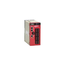
safety controller XPS-MC - 24 V DC - 32 input - 46 LEDs signalling

Preventa safety PLC compact - Safe Ethernet
Safety Controller CPU spring term. combined with backplane expansion connector

Main
| Characteristic | Value(s) |
|---|---|
| Range of Product | Twido |
| Product or Component Type | Modular base controller |
| Discrete I/O number | 40 |
| Discrete input number | 24 |
| Discrete input logic | Sink or source |
| Discrete input voltage | 24 V |
| Discrete input voltage type | DC |
| Discrete output number | 16 transistor sink) |
| [Us] rated supply voltage | 24 V DC |
| Maximum Number of I/O Expansion Module | 7 |
| Free slots | 2 |
| Use of slot | 32 K or 64 K memory cartridge and 1 realtime clock |
Complementary
| Characteristic | Value(s) |
|---|---|
| Input voltage limits | 20.4...26.4 V |
| Discrete input current | 5 mA I0.0 to I0.1 5 mA I0.6 to I0.7 7 mA I0.2 to I0.5 7 mA I0.8 to I0.23 |
| Input impedance | 4700 Ohm I0.2 to I0.5 4700 Ohm I0.8 to I0.23 5700 Ohm I0.0 to I0.1 5700 Ohm I0.6 to I0.7 |
| Filter time | 150 µs for I0.2 to I0.5 at state 0 150 µs for I0.8 to I0.23 at state 0 35 µs for I0.0 to I0.1 at state 1 35 µs for I0.6 to I0.7 at state 1 40 µs for I0.2 to I0.5 at state 1 40 µs for I0.8 to I0.23 at state 1 45 µs for I0.0 to I0.1 at state 0 45 µs for I0.6 to I0.7 at state 0 |
| Insulation between channel and internal logic | 1500 Vrms for 1 minute |
| Insulation resistance between channel | None |
| Discrete output voltage | 24 V |
| Output voltage limits | 20.4...28.8 V |
| Current per channel | 0.36 A transistor output |
| Maximum current per output common | 1 A transistor output |
| Response Time | 300 µs for Q0.2 to Q0.15 at state 0 300 µs for Q0.2 to Q0.15 at state 1 5 µs for Q0.0 to Q0.1 at state 0 5 µs for Q0.0 to Q0.1 at state 1 |
| [Ures] residual voltage | 1 V at state 1 |
| Maximum leakage current | 0.1 mA |
| Output overvoltage protection | 39 V |
| Maximum tungsten load | 8 W |
| Discrete output current | 300 mA |
| I/O connection | HE-10 connector |
| Maximum input/output number | 152 removable screw terminal block with I/O expansion module 208 spring terminal block with I/O expansion module 264 HE-10 connector with I/O expansion module |
| Supply voltage limits | 20.4â¦26.4 V |
| Protection type | Power protection internal fuse |
| Maximum power consumption in W | 19 W base + 4 expension module |
| Inrush current | 1 A transistor output 50 A power supply |
| Insulation resistance | > 10 MOhm at 500 V, between I/O and earth terminals > 10 MOhm at 500 V, between supply and earth terminals |
| Program memory | 6000 instructions with 64 K memory cartridge 3000 instructions |
| Exact time for 1 Kinstruction | 1 ms |
| System overhead | 0.5 ms |
| Memory description | Internal RAM, 128 counters, no floating, no trigonometrical Internal RAM, 128 timers, no floating, no trigonometrical Internal RAM, 256 internal bits, no floating, no trigonometrical Internal RAM, 3000 internal words, no floating, no trigonometrical Internal RAM, double words, no floating, no trigonometrical Internal RAM, floating, trigonometrical |
| Battery type | Lithium internal RAM 30 days 15 h 10 year(s) |
| Integrated connection type | Power supply Non isolated serial link mini DIN, Modbus/character mode master/slave RTU/ASCII RS485) half duplex, 38.4 kbit/s |
| Counting input number | 2 20000 Hz 32 bits 2 5000 Hz 16 bits |
| Positioning functions | PWM/PLS 2 7 kHz |
| Analogue input number | 1 |
| Analogue input range | 0...10 V |
| Analogue input resolution | 9 bits |
| Input impedance | 100000 Ohm |
| Complementary function | Event processing PID |
| Analogue adjustment points | 1 point adjustable from 0...1023 |
| Status LED | 1 LED ERR 1 LED STAT 1 LED (Green) PWR 1 LED (Green) RUN 1 LED per channel I/O status |
| Product Weight | 0.40 lb(US) (0.18 kg) |

Preventa safety PLC compact - Safe Ethernet, Modbus TCP/IP
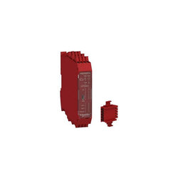
This Modicon MCM safety controller CPU is supplied with 24Vdc, has 8 safe digital inputs, 2 start/restart interlock inputs, 2 output OSSD pairs, 4 test outputs and 2 status outputs and is fitted with captive screw clamp terminals. It embeds a Mini USB 2.0 connector to receive the configuration done with the software EcoStruxure Machine Expert - HVAC. It is an appropriate solution for machines with a small number of safety functions requiring the configuration flexibility of a safety controller. It can be used as standalone or with fourteen expansion modules. The system is expandable up to 128 inputs, 16 outputs and up to 32 diagnostic status outputs, ideal for machines requiring multiple safety function monitoring. This safety controller CPU figures LEDs on its front face, displaying the status (power supply, run, internal or external errors, inputs status, communication, master enable, restart signal, output channels). It is a CPU with a rated supply voltage of 24V DC and a maximum power dissipation of 3W. It is furnished with spring clamp terminals, removable terminal block for electrical connection. It is an IP20 rated product. It weighs 0.25kg. Its dimension are 22.5mm (Depth), 99mm (Height) and 114.5mm (Width). Its housing is red. It is powered with 24 VDC. It is ideal for monitoring safety functions such as emergency stop, guard monitoring, perimeter guarding, position monitoring, speed monitoring and enabling movement. The safe controller CPU Modicon MCM are certified by TüV SÃD meeting the industrial safety standards of Category 4, PL e according to EN/ISO 13849-1 and SILCL 3 according to IEC/EN 61508 and IEC/EN 60261. Compatible accessories for Modicon MCM module are a memory card and the backplane connector. The safety controller CPU instals on Omega 35mm DIN rail conforming to EN 50022. The Modicon MCM modular safety controller system provide flexibility and scalability from 8 inputs, 2 dual/4 single channel outputs up to 128 inputs, 16 dual/32 single channel outputs, up to 32 or 48 diagnostic status outputs. Modicon MCM modular safety controller system are designed to monitor multiple safety functions on and around a machine to minimise the risk of people accessing the dangerous moving parts of the machine.
Main
| Characteristic | Value(s) |
|---|---|
| Range of Product | Modicon Safety automation |
| Device short name | XPSMCM |
| Electrical Connection | Screw terminal |
| Product or Component Type | Safety controller CPU |
| [Us] rated supply voltage | 24 V - 20...20 % DC |
| Number of inputs | 8 digital input connection 2 digital interlock start/restart or external device monitoring |
| Number of outputs | 2 safety outputs OSSD contactor/drive connection 4 test line control outputs 2 configurable diagnostic connection |
| Discrete input voltage | 24 V |
| Discrete output current | 400 mA |
| Discrete input current | 400 mA |
| Discrete input type | Safety input PNP |
| Discrete output type | PNP |
| Function of module | Emergency stop ISO 13850 Guard monitoring EN/ISO 14119 Enabling switch monitoring IEC 60947-5-1 Light curtain monitoring IEC 61496-1 Foot switch monitoring IEC 60947-5-1 Magnetic switch monitoring EN/ISO 14119 Two-hand control EN 574 Safety mat monitoring EN/ISO 14119 Enabling switch monitoring IEC 61326-1 Muting function of light curtains IEC 60947-5-1 Counter functions IEC 61800-5-2 Speed monitoring IEC 61800-5-2 |
| Backplane connector | Without |
Complementary
| Characteristic | Value(s) |
|---|---|
| Synchronisation time between inputs | < 0.5 ms |
| Power dissipation in W | 3 W |
| Maximum number of I/O expansion module | 14 128 input 14 16 output |
| Integrated connection type | Backplane expansion bus USB 2.0 port |
| Data storage equipment | SD card optional) |
| Inductive load | 30 mH |
| Load capacitance | 0.82 µF |
| Safety level | Can reach category 4 ISO 13849-1 Can reach PL = e ISO 13849-1 Type 4 IEC 61496-1 SILCL 3 IEC 62061 |
| Quality labels | CE |
| Local signalling | 1 LED green PWR power ON 1 LED green RUN RUN (status) 1 LED red E IN internal error 1 LED red E EX external error 1 LED orange COM communication 1 LED blue EN master enable 8 LEDs yellow IN input status 2 LEDs green/red OUT output status 2 LEDs yellow RST restart signal 2 LEDs yellow STATUS output channel |
| Connections - terminals | 6 captive screw terminals, removable terminal block |
| Cable cross section | 0.0003â¦0.002 in² (0.2â¦1.5 mm²) - AWG 24...AWG 16 flexible without cable end 0.0003â¦0.004 in² (0.2â¦2.5 mm²) - AWG 24...AWG 14 flexible without cable end 0.0004â¦0.002 in² (0.25â¦1 mm²) - AWG 23...AWG 18 flexible with cable end, without bezel 0.0004â¦0.004 in² (0.25â¦2.5 mm²) - AWG 23...AWG 14 flexible with cable end, with bezel 0.0004â¦0.002 in² (0.25â¦1.5 mm²) - AWG 23...AWG 16 flexible with cable end, without bezel 0.0008â¦0.002 in² (0.5â¦1.5 mm²) - AWG 20...AWG 16 flexible with cable end, with double bezel 0.0003â¦0.002 in² (0.2â¦1 mm²) - AWG 24...AWG 18 solid without cable end 0.0003â¦0.004 in² (0.2â¦2.5 mm²) - AWG 24...AWG 14 solid without cable end |
| Mounting support | Omega 35 mm DIN rail EN 50022 |
| Depth | 4.5 in (114.5 mm) |
| Height | 3.9 in (99 mm) |
| Width | 0.9 in (22.5 mm) |
| Product Weight | 0.55 lb(US) (0.25 kg) |

Main
| Characteristic | Value(s) |
|---|---|
| Range of Product | Preventa Safety automation |
| Product or Component Type | Kit configurable safety controller |
| Safety module name | XPSMC |
| Safety use category | Category 4 maximum EN 954-1/EN/ISO 13849-1 PLE maximum EN/ISO 13849-1 SIL 3 maximum IEC 61508 |
| Type of start | Configurable |
| Standards | EN 1760-1/ISO 13856-1 EN 954-1/EN/ISO 13849-1 EN/IEC 60947-5-1 EN 574/ISO 13851 IEC 61508 EN/IEC 61496-1 EN/IEC 60204-1 |
| Product Certifications | CSA TÃV UL |
| [Us] Rated Supply Voltage | 24 V DC - 20...20 % |
| Number of inputs | 16 |
| Communication port protocol | Modbus 1 RJ45, serial link 1200 bps, 2400 bps, 4800 bps, 9600 bps or 19200 bps |
| Safety level | Can reach PL e/category 4 EN 954-1/EN/ISO 13849-1 Can reach SIL 3 IEC 61508 |
Complementary
| Characteristic | Value(s) |
|---|---|
| Kit composition | Set of cage clamp terminals Set of screw terminals Ethernet cable 2m Configuration software Connection cable VDE slot screwdriver 2.5 x 75 mm Safety controller Packaging small model for software configuration Printed packaging label 80 x 50 mm USB/RS485 converter |
| Function of module | Dynamic monitoring of hydraulic valves on linear presses Eccentric press Emergency stop monitoring, with or without time delay, 1 or 2-channel wiring Enabling switch monitoring, 2 or 3 contacts Foot switch monitoring Guard monitoring for injection presses and blowing machines Guard monitoring with 1 or 2 limit switches Hydraulic press Magnetic switch monitoring Monitoring safety stop at top dead centre on eccentric press Muting function of light curtains Position selector Safety mat monitoring Safety time delays Shaft/chain breaking monitor Zero speed detection Light curtain monitoring category 4 EN/IEC 61496 Two-hand control category 3 EN 574/ISO 13851 |
| Synchronisation time between inputs | Depending on configuration selected |
| Power Consumption in W | 12 W |
| Input protection type | External fuse 16 A |
| [Uc] control circuit voltage | 28.8 V |
| Maximum line resistance | 100 Ohm <6561.7 ft (2000 m) |
| Output type | 2 relays, 2 NO contacts (4 NO total) Solid state, 6, volt-free |
| Breaking capacity | 180 VA holding AC-15 C300 relay output 1800 VA inrush AC-15 C300 relay output |
| Breaking capacity | 2 A 24 V static output circuit 1.5 A 24 V DC-13)50 ms relay output |
| Output thermal current | 4 A for both outputs simultaneously 6 A for 1 output and 2 A for the other relay output |
| [Ith] conventional free air thermal current | 16 A relay output 6.5 A static output circuit |
| Associated fuse rating | 16 A gL power supply 4 A gL relay output 6 A fast blow relay output |
| Minimum output current | 10 mA relay output |
| Minimum output voltage | 17 V relay output |
| Response Time | Configurable : 20 ms or 30 ms with software XPSMCWIN |
| [Ui] rated insulation voltage | 300 V 2)IEC 60647-5-1, DIN VDE 0110 part 1 |
| [Uimp] rated impulse withstand voltage | 4 kV III IEC 60647-5-1, DIN VDE 0110 part 1 |
| Method of access | Slave |
| Exchange size | 14 words |
| Number of addresses | 1â¦247 Modbus |
| Parity | Even Modbus No Modbus Odd Modbus |
| Data format | 1 start bit/8 data bits 1 stop bit even or odd 2 stop bits without parity RTU (Remote Terminal Unit) mode |
| Supported modbus function | 01 8-bit output data/32-bit input data 02 32-bit input data/8-bit output data 03 information and errors |
| Local signalling | 30 LEDs |
| Mounting Support | Mounting plate |
| Depth | 6.02 in (153 mm) |
| Height | 6.0 in (151.5 mm) |
| Width | 2.9 in (74 mm) |
| Product Weight | 1.81 lb(US) (0.82 kg) |

Preventa safety PLC compact - Safe Ethernet, Modbus RTU

Main
| Characteristic | Value(s) |
|---|---|
| Range of Product | Preventa Safety automation |
| Product or Component Type | Configurable safety controller |
| Safety module name | XPSMC |
| Safety use category | Category 4 maximum EN 954-1/EN/ISO 13849-1 PLE maximum ISO 13849-1 SIL 3 maximum IEC 61508 |
| Type of start | Configurable |
| Standards | EN 1760-1/ISO 13856-1 EN 574/ISO 13851 IEC 60947-5-1 IEC 61508 IEC 60204-1 EN 954-1/EN/ISO 13849-1 IEC 61496-1 |
| Product Certifications | UL CSA TÃV |
| [Us] Rated Supply Voltage | 24 V DC - 20...20 % |
| Number of inputs | 16 |
| Communication port protocol | Modbus 1 RJ45, serial link 1200 bps, 2400 bps, 4800 bps, 9600 bps or 19200 bps Profibus 1 SUB-D 9-pin female, serial link 12 Mbps |
| Safety level | Can reach PL e/category 4 EN 954-1/EN/ISO 13849-1 Can reach SIL 3 IEC 61508 |
Complementary
| Characteristic | Value(s) |
|---|---|
| Function of module | Dynamic monitoring of hydraulic valves on linear presses Eccentric press Emergency stop monitoring, with or without time delay, 1 or 2-channel wiring Enabling switch monitoring, 2 or 3 contacts Foot switch monitoring Guard monitoring for injection presses and blowing machines Guard monitoring with 1 or 2 limit switches Hydraulic press Magnetic switch monitoring category 4 EN/IEC 61496 Monitoring safety stop at top dead centre on eccentric press category 3 EN 574/ISO 13851 Muting function of light curtains Position selector Safety mat monitoring Safety time delays Shaft/chain breaking monitor Zero speed detection Light curtain monitoring category 4 IEC 61496 Two-hand control category 3 EN 574/ISO 13851 |
| Synchronisation time between inputs | Depending on configuration selected |
| Power Consumption in W | 12 W |
| Input protection type | External fuse 16 A |
| [Uc] control circuit voltage | 28.8 V |
| Maximum line resistance | 100 Ohm <6561.7 ft (2000 m) |
| Output type | 2 relays, 2 NO contacts (4 NO total) Solid state, 6, volt-free |
| Breaking capacity | 180 VA holding AC-15 C300 relay output 1800 VA inrush AC-15 C300 relay output |
| Breaking capacity | 2 A 24 V static output circuit 1.5 A 24 V DC-13)50 ms relay output |
| Output thermal current | 4 A for both outputs simultaneously 6 A for 1 output and 2 A for the other relay output |
| [Ith] conventional free air thermal current | 16 A relay output 6.5 A static output circuit |
| Associated fuse rating | 16 A gL power supply 4 A gL relay output 6 A fast blow relay output |
| Minimum output current | 10 mA relay output |
| Minimum output voltage | 17 V relay output |
| Response Time | Configurable : 20 ms or 30 ms with software XPSMCWIN |
| [Ui] rated insulation voltage | 300 V 2)IEC 60647-5-1, DIN VDE 0110 part 1 |
| [Uimp] rated impulse withstand voltage | 4 kV III IEC 60647-5-1, DIN VDE 0110 part 1 |
| Method of access | Slave |
| Exchange size | 14 words |
| Number of addresses | 1â¦125 Profibus 1â¦247 Modbus |
| Parity | Even Modbus No Modbus Odd Modbus |
| Data format | 1 start bit/8 data bits 1 stop bit even or odd 2 stop bits without parity RTU (Remote Terminal Unit) mode |
| Supported modbus function | 01 8-bit output data/32-bit input data 02 32-bit input data/8-bit output data 03 information and errors |
| Local signalling | 32 LEDs |
| Mounting Support | Mounting plate |
| Depth | 6.02 in (153 mm) |
| Height | 6.0 in (151.5 mm) |
| Width | 2.9 in (74 mm) |
| Product Weight | 1.81 lb(US) (0.82 kg) |
Controller with 8 inputs 2 outputs monitors expansion modules with spring term
Main
| Characteristic | Value(s) |
|---|---|
| Range of Product | Preventa Safety automation |
| Product or Component Type | Kit configurable safety controller |
| Safety module name | XPSMC |
| Safety use category | Category 4 maximum EN 954-1/EN/ISO 13849-1 PLE maximum EN/ISO 13849-1 SIL 3 maximum IEC 61508 |
| Type of start | Configurable |
| Standards | EN 954-1/EN/ISO 13849-1 EN/IEC 60947-5-1 EN/IEC 60204-1 EN/IEC 61496-1 IEC 61508 EN 574/ISO 13851 EN 1760-1/ISO 13856-1 |
| Product Certifications | UL CSA TÃV |
| [Us] Rated Supply Voltage | 24 V DC - 20...20 % |
| Number of inputs | 32 |
| Communication port protocol | Modbus 1 RJ45, serial link 1200 bps, 2400 bps, 4800 bps, 9600 bps or 19200 bps |
| Safety level | Can reach PL e/category 4 EN 954-1/EN/ISO 13849-1 Can reach SIL 3 IEC 61508 |
Complementary
| Characteristic | Value(s) |
|---|---|
| Kit composition | Safety controller Ethernet cable 2m Configuration software Connection cable Set of cage clamp terminals USB/RS485 converter Set of screw terminals Packaging small model for software configuration VDE slot screwdriver 2.5 x 75 mm Printed packaging label 80 x 50 mm |
| Function of module | Dynamic monitoring of hydraulic valves on linear presses Eccentric press Emergency stop monitoring, with or without time delay, 1 or 2-channel wiring Enabling switch monitoring, 2 or 3 contacts Foot switch monitoring Guard monitoring for injection presses and blowing machines Guard monitoring with 1 or 2 limit switches Hydraulic press Magnetic switch monitoring Monitoring safety stop at top dead centre on eccentric press Muting function of light curtains Position selector Safety mat monitoring Safety time delays Shaft/chain breaking monitor Zero speed detection Light curtain monitoring category 4 EN/IEC 61496 Two-hand control category 3 EN 574/ISO 13851 |
| Synchronisation time between inputs | Depending on configuration selected |
| Power Consumption in W | 12 W |
| Input protection type | External fuse 16 A |
| [Uc] control circuit voltage | 28.8 V |
| Maximum line resistance | 100 Ohm <6561.7 ft (2000 m) |
| Output type | 2 relays, 2 NO contacts (4 NO total) Solid state, 6, volt-free |
| Breaking capacity | 180 VA holding AC-15 C300 relay output 1800 VA inrush AC-15 C300 relay output |
| Breaking capacity | 2 A 24 V static output circuit 1.5 A 24 V DC-13)50 ms relay output |
| Output thermal current | 4 A for both outputs simultaneously 6 A for 1 output and 2 A for the other relay output |
| [Ith] conventional free air thermal current | 16 A relay output 6.5 A static output circuit |
| Associated fuse rating | 16 A gL power supply 4 A gL relay output 6 A fast blow relay output |
| Minimum output current | 10 mA relay output |
| Minimum output voltage | 17 V relay output |
| Response Time | Configurable : 20 ms or 30 ms with software XPSMCWIN |
| [Ui] rated insulation voltage | 300 V 2)IEC 60647-5-1, DIN VDE 0110 part 1 |
| [Uimp] rated impulse withstand voltage | 4 kV III IEC 60647-5-1, DIN VDE 0110 part 1 |
| Method of access | Slave |
| Exchange size | 14 words |
| Number of addresses | 1â¦247 Modbus |
| Parity | Even Modbus No Modbus Odd Modbus |
| Data format | 1 start bit/8 data bits 1 stop bit even or odd 2 stop bits without parity RTU (Remote Terminal Unit) mode |
| Supported modbus function | 01 8-bit output data/32-bit input data 02 32-bit input data/8-bit output data 03 information and errors |
| Local signalling | 46 LEDs |
| Mounting Support | Mounting plate |
| Depth | 6.02 in (153 mm) |
| Height | 6.0 in (151.5 mm) |
| Width | 2.9 in (74 mm) |
| Product Weight | 1.85 lb(US) (0.84 kg) |
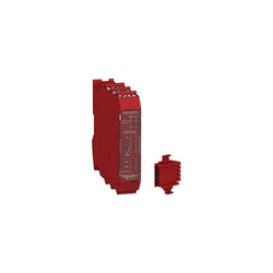
This Modicon MCM safety controller CPU is supplied with 24Vdc, has 8 safe digital inputs, 2 start/restart interlock inputs, 2 output OSSD pairs, 4 test outputs and 2 status outputs and is fitted with captive screw clamp terminals. It embeds a Mini USB 2.0 connector to receive the configuration done with the software SoSafe Configurable. It is an appropriate solution for machines with a small number of safety functions requiring the configuration flexibility of a safety controller. It can be used as standalone or with fourteen expansion modules. The system is expandable up to 128 inputs, 16 outputs and up to 32 diagnostic status outputs, ideal for machines requiring multiple safety function monitoring. This safety controller CPU figures LEDs on its front face, displaying the status (power supply, run, internal or external errors, inputs status, communication, master enable, restart signal, output channels). It is a CPU with a rated supply voltage of 24V DC and a maximum power dissipation of 3W. It is furnished with spring clamp terminals, removable terminal block for electrical connection. It is an IP20 rated product. It weighs 0.26kg. Its dimension are 22.5mm (Depth), 99mm (Height) and 114.5mm (Width). Its housing is red. It is powered with 24 VDC. It is ideal for monitoring safety functions such as emergency stop, guard monitoring, perimeter guarding, position monitoring, speed monitoring and enabling movement. The safe controller CPU Modicon MCM are certified by TüV SÃD meeting the industrial safety standards of Category 4, PL e according to EN/ISO 13849-1 and SILCL 3 according to IEC/EN 61508 and IEC/EN 60261. Compatible accessories for Modicon MCM module are a memory card and the backplane connector. The kit includes 1 x safety controller CPU and 1 x backplane expansion connector. The safety controller CPU instals on Omega 35mm DIN rail conforming to EN 50022. The Modicon MCM modular safety controller system provide flexibility and scalability from 8 inputs, 2 dual/4 single channel outputs up to 128 inputs, 16 dual/32 single channel outputs, up to 32 or 48 diagnostic status outputs. Modicon MCM modular safety controller system are designed to monitor multiple safety functions on and around a machine to minimise the risk of people accessing the dangerous moving parts of the machine.
Main
| Characteristic | Value(s) |
|---|---|
| Range of Product | Modicon Safety automation |
| Device short name | XPSMCM |
| Electrical Connection | Screw terminal |
| Product or Component Type | Modular safety controller CPU kit |
| [Us] rated supply voltage | 24 V - 20...20 % DC |
| Number of inputs | 8 digital input connection 2 digital interlock start/restart or external device monitoring |
| Number of outputs | 2 safety outputs OSSD contactor/drive connection 4 test line control outputs 2 configurable diagnostic connection |
| Discrete input voltage | 24 V |
| Discrete output current | 400 mA |
| Discrete input current | 400 mA |
| Discrete input type | PNP Safety input |
| Discrete output type | PNP |
| Kit composition | 1 safety controller CPU 1 backplane expansion connector |
| Function of module | Emergency stop ISO 13850 Guard monitoring EN/ISO 14119 Enabling switch monitoring IEC 60947-5-1 Light curtain monitoring IEC 61496-1 Foot switch monitoring IEC 60947-5-1 Magnetic switch monitoring EN/ISO 14119 Two-hand control EN 574 Safety mat monitoring EN/ISO 14119 Enabling switch monitoring IEC 61326-1 Muting function of light curtains IEC 60947-5-1 Counter functions IEC 61800-5-2 Speed monitoring IEC 61800-5-2 |
| Backplane connector | With |
Complementary
| Characteristic | Value(s) |
|---|---|
| Synchronisation time between inputs | < 0.5 ms |
| Power dissipation in W | 3 W |
| Maximum number of I/O expansion module | 14 128 input 14 16 output |
| Integrated connection type | Backplane expansion bus USB 2.0 port |
| Data storage equipment | SD card optional) |
| Inductive load | 30 mH |
| Load capacitance | 0.82 µF |
| Safety level | Can reach category 4 ISO 13849-1 Can reach PL = e ISO 13849-1 Type 4 IEC 61496-1 SILCL 3 IEC 62061 |
| Quality labels | CE |
| Local signalling | 1 LED green PWR power ON 1 LED green RUN RUN (status) 1 LED red E IN internal error 1 LED red E EX external error 1 LED orange COM communication 1 LED blue EN master enable 8 LEDs yellow IN input status 2 LEDs green/red OUT output status 2 LEDs yellow RST restart signal 2 LEDs yellow STATUS output channel |
| Connections - terminals | 2 captive screw terminals, removable terminal block 1 captive screw terminals, removable terminal block |
| Cable cross section | 0.0003â¦0.002 in² (0.2â¦1.5 mm²) - AWG 24...AWG 16 flexible without cable end 0.0003â¦0.004 in² (0.2â¦2.5 mm²) - AWG 24...AWG 14 flexible without cable end 0.0004â¦0.002 in² (0.25â¦1 mm²) - AWG 23...AWG 18 flexible with cable end, without bezel 0.0004â¦0.004 in² (0.25â¦2.5 mm²) - AWG 23...AWG 14 flexible with cable end, with bezel 0.0004â¦0.002 in² (0.25â¦1.5 mm²) - AWG 23...AWG 16 flexible with cable end, without bezel 0.0008â¦0.002 in² (0.5â¦1.5 mm²) - AWG 20...AWG 16 flexible with cable end, with double bezel 0.0003â¦0.002 in² (0.2â¦1 mm²) - AWG 24...AWG 18 solid without cable end 0.0003â¦0.004 in² (0.2â¦2.5 mm²) - AWG 24...AWG 14 solid without cable end |
| Mounting support | Omega 35 mm DIN rail EN 50022 |
| Depth | 4.5 in (114.5 mm) |
| Height | 3.9 in (99 mm) |
| Width | 0.9 in (22.5 mm) |
| Product Weight | 0.57 lb(US) (0.26 kg) |

Main
| Characteristic | Value(s) |
|---|---|
| Range of Product | Twido |
| Product or Component Type | Compact base controller |
| Discrete I/O number | 16 |
| Discrete input number | 9 |
| Discrete input voltage | 24 V |
| Discrete input voltage type | DC |
| Discrete output number | 7 relay |
| [Us] rated supply voltage | 24 V DC |
| Use of slot | Memory cartridge or realtime clock cartridge |
| Data backed up | Internal RAM lithium, 30 days 10 h 10 year(s) |
| Integrated connection type | Power supply Non isolated serial link mini DIN, Modbus/character mode master/slave RTU/ASCII RS485) half duplex, 38.4 kbit/s Serial link interface adaptor RS232C/RS485) |
| Range Compatibility | Twido |
Complementary
| Characteristic | Value(s) |
|---|---|
| Discrete input logic | Sink or source |
| Input voltage limits | 20.4...28.8 V |
| Discrete input current | 11 mA I0.0 to I0.1 7 mA I0.2 to I0.8 |
| Input impedance | 2100 Ohm I0.2 to I0.8 3400 Ohm I0.0 to I0.1 |
| Filter time | 150 µs + programmed filter time for I0.6 to I0.8 at state 0 35 µs + programmed filter time for I0.0 to I0.5 at state 1 40 µs + programmed filter time for I0.6 to I0.8 at state 1 45 µs + programmed filter time for I0.0 to I0.5 at state 0 |
| Insulation between channel and internal logic | 1500 Vrms for 1 minute |
| Insulation resistance between channel | None |
| Minimum load | 0.1 mA |
| Contact resistance | 30000 µOhm |
| Load current | 2 A 240 V AC inductive 30 cyc/mn relay output 2 A 240 V AC resistive 30 cyc/mn relay output 2 A 30 V DC inductive 30 cyc/mn relay output 2 A 30 V DC resistive 30 cyc/mn relay output |
| Mechanical durability | 20000000 cycles relay output |
| Electrical durability | 100000 cycles relay output |
| Current consumption | 30 mA 5 V DC at state 1 40 mA 24 V DC at state 1 5 mA 5 V DC at state 0 |
| I/O connection | Non-removable screw terminal block |
| Supply voltage limits | 20.4â¦28.8 V |
| Inrush current | 35 A |
| Protection type | Power protection internal fuse |
| Power Consumption in W | 4.6 W |
| Insulation resistance | > 10 MOhm at 500 V, between I/O and earth terminals > 10 MOhm at 500 V, between supply and earth terminals |
| Program memory | 2000 instructions |
| Exact time for 1 Kinstruction | 1 ms |
| System overhead | 0.5 ms |
| Memory description | Internal RAM, 128 counters, no floating, no trigonometrical Internal RAM, 128 internal bits, no floating, no trigonometrical Internal RAM, 3000 internal words, no floating, no trigonometrical Internal RAM, 64 timers, no floating, no trigonometrical Internal RAM, double words, no floating, no trigonometrical |
| Free slots | 1 |
| Realtime clock | Without |
| Counting input number | 1 20000 Hz 32 bits 3 5000 Hz 16 bits |
| Analogue adjustment points | 1 point adjustable from 0...1023 |
| Status LED | 1 LED (Green) PWR 1 LED (Green) RUN 1 LED per channel (Green) I/O status 1 LED (Red) module error (ERR) 1 LED user pilot light (STAT) |
| Depth | 2.8 in (70 mm) |
| Height | 3.7 in (95 mm) |
| Width | 3.5 in (90 mm) |
| Product Weight | 0.55 lb(US) (0.25 kg) |
Main
| Characteristic | Value(s) |
|---|---|
| Range of Product | Twido |
| Product or Component Type | Compact base controller |
| Concept | Transparent Ready |
| Discrete I/O number | 40 |
| Discrete input number | 24 |
| Discrete input voltage | 24 V |
| Discrete input voltage type | DC |
| Discrete output number | 14 relay 2 transistor |
| [Us] rated supply voltage | 24 V DC |
| Maximum Number of I/O Expansion Module | 7 |
| Use of slot | Memory cartridge |
| Data backed up | Internal RAM lithium, 30 days 10 h 10 year(s) |
| Integrated connection type | Power supply Non isolated serial link mini DIN, Modbus/character mode master/slave RTU/ASCII RS485) half duplex, 38.4 kbit/s Serial link interface adaptor RS232C/RS485) Ethernet TCP/IP RJ45, , 10/100 Mbit/s, 1 twisted pair transparent ready class A10 |
| Complementary function | Event processing PID |
| Range Compatibility | Twido |
Complementary
| Characteristic | Value(s) |
|---|---|
| Discrete input logic | Sink or source |
| Input voltage limits | 20.4...26.4 V |
| Discrete input current | 11 mA I0.0 to I0.1 11 mA I0.6 to I0.7 7 mA I0.2 to I0.5 7 mA I0.8 to I0.23 |
| Input impedance | 2100 Ohm I0.0 to I0.1 2100 Ohm I0.6 to I0.7 3400 Ohm I0.2 to I0.5 3400 Ohm I0.8 to I0.23 |
| Filter time | 150 µs + programmed filter time for I0.6 to I0.23 at state 0 35 µs + programmed filter time for I0.0 to I0.5 at state 1 40 µs + programmed filter time for I0.0 to I0.5 at state 0 40 µs + programmed filter time for I0.6 to I0.23 at state 1 |
| Insulation between channel and internal logic | 1500 Vrms for 1 minute |
| Insulation resistance between channel | None |
| Minimum load | 0.1 mA |
| Contact resistance | 30000 µOhm |
| Load current | 2 A 240 V AC inductive 30 cyc/mn relay output 2 A 240 V AC resistive 30 cyc/mn relay output 2 A 30 V DC inductive 30 cyc/mn relay output 2 A 30 V DC resistive 30 cyc/mn relay output |
| Mechanical durability | 20000000 cycles relay output |
| Electrical durability | 100000 cycles relay output |
| Current consumption | 128 mA 24 V DC at state 1 128 mA 24 V DC state 1 + input ON 170 mA 5 V DC at state 0 240 mA 5 V DC state 1 + input ON 5 mA 24 V DC at state 0 90 mA 5 V DC at state 1 |
| I/O connection | Non-removable screw terminal block |
| Maximum input/output number | 152 removable screw terminal block with I/O expansion module 208 spring terminal block with I/O expansion module 264 HE-10 connector with I/O expansion module |
| Supply voltage limits | 20.4â¦28.8 V |
| Inrush current | 35 A |
| Protection type | Power protection internal fuse |
| Power Consumption in W | 17.2 W |
| Insulation resistance | > 10 MOhm at 500 V, between I/O and earth terminals > 10 MOhm at 500 V, between supply and earth terminals |
| Program memory | 3000 instructions |
| Exact time for 1 Kinstruction | 1 ms |
| System overhead | 0.5 ms |
| Memory description | Internal RAM, 128 counters, no floating, no trigonometrical Internal RAM, 128 timers, no floating, no trigonometrical Internal RAM, 256 internal bits, no floating, no trigonometrical Internal RAM, 3000 internal words, no floating, no trigonometrical Internal RAM, double words, no floating, no trigonometrical Internal RAM, floating, trigonometrical |
| Free slots | 1 |
| Realtime clock | With <= 30 s/month 30 days |
| Port Ethernet | 10BASE-T/100BASE-TX |
| Communication service | BOOTP client, Ethernet TCP/IP Modbus messaging, Ethernet TCP/IP |
| Positioning functions | PWM/PLS 2 7 kHz |
| Counting input number | 2 20000 Hz 32 bits 4 5000 Hz 16 bits |
| Analogue adjustment points | 1 point adjustable from 0 to 511 points 1 point adjustable from 0...1023 |
| Status LED | 1 LED (Green) PWR 1 LED (Green) RUN 1 LED per channel (Green) I/O status 1 LED (Red) module error (ERR) 1 LED user pilot light (STAT) 1 LED 10 or 100 Mbit/s rate (LACT) 1 LED Ethernet status (LAN ST) |
| Depth | 2.8 in (70 mm) |
| Height | 3.7 in (95 mm) |
| Width | 3.5 in (90 mm) |
| Product Weight | 1.157 lb(US) (0.525 kg) |
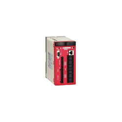
This product is part of preventa XPCMC configurable safety controller range. It is a configurable safety controller. It is supplied with 24 V DC. It has 32 safety inputs. It conforms to Category 4 maximum conforming to EN 954-1/EN/ISO 13849-1, PLE safety level conforming to EN/ISO 13849-1 and SIL 3 level conforming to IEC 61508. It embeds 1 RJ45 port for a serial link communication with Modbus protocol. The transmission rate are 1200bps, 2400bps, 4800bps, 9600bps or 19200bps, and 1 SUB-D 9-pin female port for PROFIBUS communication. The transmission rate is 12Mbps. This product measures 153mm depth, 151.5mm height, and 74mm width. It weighs 0.84kg. This safety controller is designed for monitoring multiple safety functions such as emergency stop, guard monitoring, perimeter guarding, position monitoring, speed monitoring and enabling movement. This product is certified by CSA, UL and TÃV. It conforms to EN 954-1/EN/ISO 13849-1, EN/IEC 61496-1, IEC 61508, EN/IEC 60204-1, EN 1760-1/ISO 13856-1, EN 574/ISO 13851 and EN/IEC 60947-5-1 standards. The Safety controller XPSMC is configurable and addressable using software XPSMCWIN running on a PC and using a USB/RJ45 cable type TCSMCNAM3M002P to connect to the safety controller. It installs with a mounting plate for mounting on rail. Preventa XPSMC configurable safety controller is designed to provide a solution for safety applications requiring conformity to Performance Level PL e/Category 4 EN ISO 13849-1 and SIL3 EN/IEC 61508. The configurable safety controller consists of 6 variants with 16 or 32 digital inputs and 8 digital outputs and communication possibilities of Modbus RTL Serial, Profibus DP and CANopen.
Main
| Characteristic | Value(s) |
|---|---|
| Range of Product | Preventa Safety automation |
| Product or Component Type | Configurable safety controller |
| Safety module name | XPSMC |
| Safety use category | Category 4 maximum EN 954-1/EN/ISO 13849-1 PLE maximum ISO 13849-1 SIL 3 maximum IEC 61508 |
| Type of start | Configurable |
| Standards | EN 954-1/EN/ISO 13849-1 IEC 61496-1 IEC 61508 IEC 60204-1 EN 1760-1/ISO 13856-1 EN 574/ISO 13851 IEC 60947-5-1 |
| Product Certifications | CSA UL TÃV |
| [Us] Rated Supply Voltage | 24 V DC - 20...20 % |
| Number of inputs | 32 |
| Communication port protocol | Modbus 1 RJ45, serial link 1200 bps, 2400 bps, 4800 bps, 9600 bps or 19200 bps Profibus 1 SUB-D 9-pin female, serial link 12 Mbps |
| Safety level | Can reach PL e/category 4 EN 954-1/EN/ISO 13849-1 Can reach SIL 3 IEC 61508 |
Complementary
| Characteristic | Value(s) |
|---|---|
| Function of module | Dynamic monitoring of hydraulic valves on linear presses Eccentric press Emergency stop monitoring, with or without time delay, 1 or 2-channel wiring Enabling switch monitoring, 2 or 3 contacts Foot switch monitoring Guard monitoring for injection presses and blowing machines Guard monitoring with 1 or 2 limit switches Hydraulic press Magnetic switch monitoring category 4 EN/IEC 61496 Monitoring safety stop at top dead centre on eccentric press category 3 EN 574/ISO 13851 Muting function of light curtains Position selector Safety mat monitoring Safety time delays Shaft/chain breaking monitor Zero speed detection Light curtain monitoring category 4 IEC 61496 Two-hand control category 3 EN 574/ISO 13851 |
| Synchronisation time between inputs | Depending on configuration selected |
| Power Consumption in W | 12 W |
| Input protection type | External fuse 16 A |
| [Uc] control circuit voltage | 28.8 V |
| Maximum line resistance | 100 Ohm <6561.7 ft (2000 m) |
| Output type | 2 relays, 2 NO contacts (4 NO total) Solid state, 6, volt-free |
| Breaking capacity | 180 VA holding AC-15 C300 relay output 1800 VA inrush AC-15 C300 relay output |
| Breaking capacity | 2 A 24 V static output circuit 1.5 A 24 V DC-13)50 ms relay output |
| Output thermal current | 4 A for both outputs simultaneously 6 A for 1 output and 2 A for the other relay output |
| [Ith] conventional free air thermal current | 16 A relay output 6.5 A static output circuit |
| Associated fuse rating | 16 A gL power supply 4 A gL relay output 6 A fast blow relay output |
| Minimum output current | 10 mA relay output |
| Minimum output voltage | 17 V relay output |
| Response Time | Configurable : 20 ms or 30 ms with software XPSMCWIN |
| [Ui] rated insulation voltage | 300 V 2)IEC 60647-5-1, DIN VDE 0110 part 1 |
| [Uimp] rated impulse withstand voltage | 4 kV III IEC 60647-5-1, DIN VDE 0110 part 1 |
| Method of access | Slave |
| Exchange size | 14 words |
| Number of addresses | 1â¦125 Profibus 1â¦247 Modbus |
| Parity | Even Modbus No Modbus Odd Modbus |
| Data format | 1 start bit/8 data bits 1 stop bit even or odd 2 stop bits without parity RTU (Remote Terminal Unit) mode |
| Supported modbus function | 01 8-bit output data/32-bit input data 02 32-bit input data/8-bit output data 03 information and errors |
| Local signalling | 48 LEDs |
| Mounting Support | Mounting plate |
| Depth | 6.02 in (153 mm) |
| Height | 6.0 in (151.5 mm) |
| Width | 2.9 in (74 mm) |
| Product Weight | 1.85 lb(US) (0.84 kg) |

Main
| Characteristic | Value(s) |
|---|---|
| Range of Product | Twido |
| Product or Component Type | Modular base controller |
| Discrete I/O number | 20 |
| Discrete input number | 12 |
| Discrete input logic | Sink or source |
| Discrete input voltage | 24 V |
| Discrete input voltage type | DC |
| Discrete output number | 8 transistor sink) |
| [Us] rated supply voltage | 24 V DC |
| Maximum Number of I/O Expansion Module | 4 |
| Free slots | 2 |
| Use of slot | 32 K memory cartridge and 1 realtime clock |
Complementary
| Characteristic | Value(s) |
|---|---|
| Input voltage limits | 20.4...26.4 V |
| Discrete input current | 5 mA I0.0 to I0.1 5 mA I0.6 to I0.7 7 mA I0.2 to I0.5 7 mA I0.8 to I0.11 |
| Input impedance | 4700 Ohm I0.2 to I0.5 4700 Ohm I0.8 to I0.11 5700 Ohm I0.0 to I0.1 5700 Ohm I0.6 to I0.7 |
| Filter time | 150 µs for I0.2 to I0.5 at state 0 150 µs for I0.8 to I0.11 at state 0 35 µs for I0.0 to I0.1 at state 1 35 µs for I0.6 to I0.7 at state 1 40 µs for I0.2 to I0.5 at state 1 40 µs for I0.8 to I0.11 at state 1 45 µs for I0.0 to I0.1 at state 0 45 µs for I0.6 to I0.7 at state 0 |
| Insulation between channel and internal logic | 1500 Vrms for 1 minute |
| Insulation resistance between channel | None |
| Discrete output voltage | 24 V |
| Output voltage limits | 20.4...28.8 V |
| Current per channel | 0.36 A transistor output |
| Maximum current per output common | 1 A transistor output |
| Response Time | 300 µs for Q0.2 to Q0.7 at state 0 300 µs for Q0.2 to Q0.7 at state 1 5 µs for Q0.0 to Q0.1 at state 0 5 µs for Q0.0 to Q0.1 at state 1 |
| [Ures] residual voltage | 1 V at state 1 |
| Maximum leakage current | 0.1 mA |
| Output overvoltage protection | 39 V |
| Maximum tungsten load | 8 W |
| Discrete output current | 300 mA |
| I/O connection | HE-10 connector |
| Maximum input/output number | 116 spring terminal block with I/O expansion module 148 HE-10 connector with I/O expansion module 88 removable screw terminal block with I/O expansion module |
| Supply voltage limits | 20.4â¦26.4 V |
| Protection type | Power protection internal fuse |
| Maximum power consumption in W | 15 W base + 4 expension module |
| Inrush current | 1 A transistor output 50 A power supply |
| Insulation resistance | > 10 MOhm at 500 V, between I/O and earth terminals > 10 MOhm at 500 V, between supply and earth terminals |
| Program memory | 3000 instructions |
| Exact time for 1 Kinstruction | 1 ms |
| System overhead | 0.5 ms |
| Memory description | Internal RAM, 128 counters, no floating, no trigonometrical Internal RAM, 128 timers, no floating, no trigonometrical Internal RAM, 256 internal bits, no floating, no trigonometrical Internal RAM, 3000 internal words, no floating, no trigonometrical Internal RAM, double words, no floating, no trigonometrical |
| Battery type | Lithium internal RAM 30 days 15 h 10 year(s) |
| Integrated connection type | Power supply Non isolated serial link mini DIN, Modbus/character mode master/slave RTU/ASCII RS485) half duplex, 38.4 kbit/s |
| Counting input number | 2 20000 Hz 32 bits 2 5000 Hz 16 bits |
| Positioning functions | PWM/PLS 2 7 kHz |
| Analogue input number | 1 |
| Analogue input range | 0...10 V |
| Analogue input resolution | 9 bits |
| Input impedance | 100000 Ohm |
| Complementary function | PID Event processing |
| Analogue adjustment points | 1 point adjustable from 0...1023 |
| Status LED | 1 LED ERR 1 LED STAT 1 LED (Green) PWR 1 LED (Green) RUN 1 LED per channel I/O status |

safety controller XPS-MC - 24 V DC - 16 input - 32 LEDs signalling

Main
| Characteristic | Value(s) |
|---|---|
| Range of Product | Twido |
| Product or Component Type | Compact base controller |
| Discrete I/O number | 24 |
| Discrete input number | 14 |
| Discrete input voltage | 24 V |
| Discrete input voltage type | DC |
| Discrete output number | 10 relay |
| [Us] rated supply voltage | 24 V DC |
| Maximum Number of I/O Expansion Module | 4 |
| Use of slot | Memory cartridge or realtime clock cartridge |
| Data backed up | Internal RAM lithium, 30 days 10 h 10 year(s) |
| Integrated connection type | Power supply Non isolated serial link mini DIN, Modbus/character mode master/slave RTU/ASCII RS485) half duplex, 38.4 kbit/s Serial link interface adaptor RS232C/RS485) |
| Complementary function | Event processing PID |
| Range Compatibility | Twido |
Complementary
| Characteristic | Value(s) |
|---|---|
| Discrete input logic | Sink or source |
| Input voltage limits | 20.4...28.8 V |
| Discrete input current | 11 mA I0.0 to I0.1 7 mA I0.2 to I0.13 |
| Input impedance | 2100 Ohm I0.0 to I0.1 3400 Ohm I0.2 to I0.13 |
| Filter time | 150 µs + programmed filter time for I0.6 to I0.13 at state 0 35 µs + programmed filter time for I0.0 to I0.5 at state 1 40 µs + programmed filter time for I0.6 to I0.13 at state 1 45 µs + programmed filter time for I0.0 to I0.5 at state 0 |
| Insulation between channel and internal logic | 1500 Vrms for 1 minute |
| Insulation resistance between channel | None |
| Minimum load | 0.1 mA |
| Contact resistance | 30000 µOhm |
| Load current | 2 A 240 V AC inductive 30 cyc/mn relay output 2 A 240 V AC resistive 30 cyc/mn relay output 2 A 30 V DC inductive 30 cyc/mn relay output 2 A 30 V DC resistive 30 cyc/mn relay output |
| Mechanical durability | 20000000 cycles relay output |
| Electrical durability | 100000 cycles relay output |
| Current consumption | 36 mA 5 V DC at state 1 5 mA 5 V DC at state 0 55 mA 24 V DC at state 1 |
| I/O connection | Non-removable screw terminal block |
| Maximum input/output number | 120 spring terminal block with I/O expansion module 152 HE-10 connector with I/O expansion module 88 removable screw terminal block with I/O expansion module |
| Supply voltage limits | 20.4â¦28.8 V |
| Inrush current | 40 A |
| Protection type | Power protection internal fuse |
| Power Consumption in W | 8.7 W |
| Insulation resistance | > 10 MOhm at 500 V, between I/O and earth terminals > 10 MOhm at 500 V, between supply and earth terminals |
| Program memory | 3000 instructions |
| Exact time for 1 Kinstruction | 1 ms |
| System overhead | 0.5 ms |
| Memory description | Internal RAM, 128 counters, no floating, no trigonometrical Internal RAM, 128 timers, no floating, no trigonometrical Internal RAM, 256 internal bits, no floating, no trigonometrical Internal RAM, 3000 internal words, no floating, no trigonometrical Internal RAM, double words, no floating, no trigonometrical |
| Free slots | 1 |
| Realtime clock | Without |
| Counting input number | 1 20000 Hz 32 bits 3 5000 Hz 16 bits |
| Analogue adjustment points | 1 point adjustable from 0 to 511 points 1 point adjustable from 0...1023 |
| Status LED | 1 LED (Green) PWR 1 LED (Green) RUN 1 LED per channel (Green) I/O status 1 LED (Red) module error (ERR) 1 LED user pilot light (STAT) |
| Depth | 2.8 in (70 mm) |
| Height | 3.7 in (95 mm) |
| Width | 3.5 in (90 mm) |
| Product Weight | 0.672 lb(US) (0.305 kg) |