
 1 year warranty


Ordering
1 piece
85364900
Popular Downloads
Dimensions
45 mm
77 mm
86 mm
0.27 kg
Technical
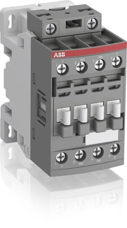
3
0
1
0
3P
IEC/EN 60947-1, IEC/EN 60947-4-1, UL 60335-2-40 LZGH2 A2L, UL 60947-4-1, CSA C22.2 No. 60335-2-40 LZGH2 A2L, CSA C22.2 No. 60947-4-1
Auxiliary Circuit 690 V
Main Circuit 690 V
Auxiliary Circuit 690 V
Main Circuit 690 V
Auxiliary Circuit 50 / 60 Hz
Control Circuit 50 / 60 Hz
Main Circuit 50 / 60 Hz
Auxiliary Circuit 50 / 60 Hz
Control Circuit 50 / 60 Hz
Main Circuit 50 / 60 Hz
acc. to IEC 60947-4-1, Open Contactors Θ = 40 °C 35 A
acc. to IEC 60947-5-1, Θ = 40 °C 16 A
acc. to IEC 60947-4-1, Open Contactors Θ = 40 °C 35 A
acc. to IEC 60947-5-1, Θ = 40 °C 16 A
(690 V) 40 °C 30 A
(690 V) 60 °C 30 A
(690 V) 70 °C 26 A
(690 V) 40 °C 30 A
(690 V) 60 °C 30 A
(690 V) 70 °C 26 A
(415 V) 60 °C 18 A
(440 V) 60 °C 18 A
(500 V) 60 °C 15 A
(690 V) 60 °C 10.5 A
(380 / 400 V) 60 °C 18 A
(220 / 230 / 240 V) 60 °C 18 A
(415 V) 60 °C 18 A
(440 V) 60 °C 18 A
(500 V) 60 °C 15 A
(690 V) 60 °C 10.5 A
(380 / 400 V) 60 °C 18 A
(220 / 230 / 240 V) 60 °C 18 A
(415 V) 60 °C 18 A
(440 V) 60 °C 18 A
(500 V) 60 °C 15 A
(690 V) 60 °C 10.5 A
(380 / 400 V) 60 °C 18 A
(220 / 230 / 240 V) 60 °C 18 A
(415 V) 60 °C 18 A
(440 V) 60 °C 18 A
(500 V) 60 °C 15 A
(690 V) 60 °C 10.5 A
(380 / 400 V) 60 °C 18 A
(220 / 230 / 240 V) 60 °C 18 A
(500 V) 2 A
(690 V) 2 A
(24 / 127 V) 6 A
(220 / 240 V) 4 A
(400 / 440 V) 3 A
(500 V) 2 A
(690 V) 2 A
(24 / 127 V) 6 A
(220 / 240 V) 4 A
(400 / 440 V) 3 A
(110 V) 1-Pole, 40 °C 20 A
(110 V) 1-Pole, 60 °C 20 A
(110 V) 1-Pole, 70 °C 20 A
(110 V) 2 Poles in Series, 40 °C 30 A
(110 V) 2 Poles in Series, 60 °C 30 A
(110 V) 2 Poles in Series, 70 °C 26 A
(110 V) 3 Poles in Series, 40 °C 30 A
(110 V) 3 Poles in Series, 60 °C 30 A
(110 V) 3 Poles in Series, 70 °C 26 A
(220 V) 2 Poles in Series, 40 °C 20 A
(220 V) 2 Poles in Series, 60 °C 20 A
(220 V) 2 Poles in Series, 70 °C 20 A
(220 V) 3 Poles in Series, 40 °C 30 A
(220 V) 3 Poles in Series, 60 °C 30 A
(220 V) 3 Poles in Series, 70 °C 26 A
(72 V) 1-Pole, 40 °C 30 A
(72 V) 1-Pole, 60 °C 30 A
(72 V) 1-Pole, 70 °C 26 A
(72 V) 2 Poles in Series, 40 °C 30 A
(72 V) 2 Poles in Series, 60 °C 30 A
(72 V) 2 Poles in Series, 70 °C 26 A
(72 V) 3 Poles in Series, 40 °C 30 A
(72 V) 3 Poles in Series, 60 °C 30 A
(72 V) 3 Poles in Series, 70 °C 26 A
(110 V) 1-Pole, 40 °C 20 A
(110 V) 1-Pole, 60 °C 20 A
(110 V) 1-Pole, 70 °C 20 A
(110 V) 2 Poles in Series, 40 °C 30 A
(110 V) 2 Poles in Series, 60 °C 30 A
(110 V) 2 Poles in Series, 70 °C 26 A
(110 V) 3 Poles in Series, 40 °C 30 A
(110 V) 3 Poles in Series, 60 °C 30 A
(110 V) 3 Poles in Series, 70 °C 26 A
(220 V) 2 Poles in Series, 40 °C 20 A
(110 V) 1-Pole, 40 °C 8 A
(110 V) 1-Pole, 60 °C 8 A
(110 V) 1-Pole, 70 °C 8 A
(110 V) 2 Poles in Series, 40 °C 30 A
(110 V) 2 Poles in Series, 60 °C 30 A
(110 V) 2 Poles in Series, 70 °C 26 A
(110 V) 3 Poles in Series, 40 °C 30 A
(110 V) 3 Poles in Series, 60 °C 30 A
(110 V) 3 Poles in Series, 70 °C 26 A
(220 V) 2 Poles in Series, 40 °C 8 A
(220 V) 2 Poles in Series, 60 °C 8 A
(220 V) 2 Poles in Series, 70 °C 8 A
(220 V) 3 Poles in Series, 40 °C 30 A
(220 V) 3 Poles in Series, 60 °C 30 A
(220 V) 3 Poles in Series, 70 °C 26 A
(72 V) 1-Pole, 40 °C 30 A
(72 V) 1-Pole, 60 °C 30 A
(72 V) 1-Pole, 70 °C 26 A
(72 V) 2 Poles in Series, 40 °C 30 A
(72 V) 2 Poles in Series, 60 °C 30 A
(72 V) 2 Poles in Series, 70 °C 26 A
(72 V) 3 Poles in Series, 40 °C 30 A
(72 V) 3 Poles in Series, 60 °C 30 A
(72 V) 3 Poles in Series, 70 °C 26 A
(110 V) 1-Pole, 40 °C 8 A
(110 V) 1-Pole, 60 °C 8 A
(110 V) 1-Pole, 70 °C 8 A
(110 V) 2 Poles in Series, 40 °C 30 A
(110 V) 2 Poles in Series, 60 °C 30 A
(110 V) 2 Poles in Series, 70 °C 26 A
(110 V) 3 Poles in Series, 40 °C 30 A
(110 V) 3 Poles in Series, 60 °C 30 A
(110 V) 3 Poles in Series, 70 °C 26 A
(220 V) 2 Poles in Series, 40 °C 8 A
(110 V) 1-Pole, 40 °C 4 A
(110 V) 1-Pole, 60 °C 4 A
(110 V) 1-Pole, 70 °C 4 A
(110 V) 2 Poles in Series, 40 °C 20 A
(110 V) 2 Poles in Series, 60 °C 20 A
(110 V) 2 Poles in Series, 70 °C 20 A
(110 V) 3 Poles in Series, 40 °C 30 A
(110 V) 3 Poles in Series, 60 °C 30 A
(110 V) 3 Poles in Series, 70 °C 26 A
(220 V) 2 Poles in Series, 40 °C 4 A
(220 V) 2 Poles in Series, 60 °C 4 A
(220 V) 2 Poles in Series, 70 °C 4 A
(220 V) 3 Poles in Series, 40 °C 16 A
(220 V) 3 Poles in Series, 60 °C 16 A
(220 V) 3 Poles in Series, 70 °C 16 A
(72 V) 1-Pole, 40 °C 16 A
(72 V) 1-Pole, 60 °C 16 A
(72 V) 1-Pole, 70 °C 16 A
(72 V) 2 Poles in Series, 40 °C 30 A
(72 V) 2 Poles in Series, 60 °C 30 A
(72 V) 2 Poles in Series, 70 °C 26 A
(72 V) 3 Poles in Series, 40 °C 30 A
(72 V) 3 Poles in Series, 60 °C 30 A
(72 V) 3 Poles in Series, 70 °C 26 A
(110 V) 1-Pole, 40 °C 4 A
(110 V) 1-Pole, 60 °C 4 A
(110 V) 1-Pole, 70 °C 4 A
(110 V) 2 Poles in Series, 40 °C 20 A
(110 V) 2 Poles in Series, 60 °C 20 A
(110 V) 2 Poles in Series, 70 °C 20 A
(110 V) 3 Poles in Series, 40 °C 30 A
(110 V) 3 Poles in Series, 60 °C 30 A
(110 V) 3 Poles in Series, 70 °C 26 A
(220 V) 2 Poles in Series, 40 °C 4 A
(24 V) 6 A / 144 W
(48 V) 2.8 A / 134 W
(72 V) 1 A / 72 W
(110 V) 0.55 A / 60 W
(125 V) 0.55 A / 69 W
(220 V) 0.27 A / 60 W
(250 V) 0.27 A / 68 W
(400 V) 0.15 A / 60 W
(500 V) 0.13 A / 65 W
(600 V) 0.1 A / 60 W
(24 V) 6 A / 144 W
(48 V) 2.8 A / 134 W
(72 V) 1 A / 72 W
(110 V) 0.55 A / 60 W
(125 V) 0.55 A / 69 W
(220 V) 0.27 A / 60 W
(250 V) 0.27 A / 68 W
(400 V) 0.15 A / 60 W
(500 V) 0.13 A / 65 W
(600 V) 0.1 A / 60 W
(400 V) 7.5 kW
(415 V) 9 kW
(440 V) 9 kW
(500 V) 9 kW
(690 V) 9 kW
(380 / 400 V) 7.5 kW
(220 / 230 / 240 V) 4 kW
(400 V) 7.5 kW
(415 V) 9 kW
(440 V) 9 kW
(500 V) 9 kW
(690 V) 9 kW
(380 / 400 V) 7.5 kW
(220 / 230 / 240 V) 4 kW
(415 V) 9 kW
(440 V) 9 kW
(500 V) 9 kW
(690 V) 9 kW
(380 / 400 V) 7.5 kW
(220 / 230 / 240 V) 4 kW
(415 V) 9 kW
(440 V) 9 kW
(500 V) 9 kW
(690 V) 9 kW
(380 / 400 V) 7.5 kW
(220 / 230 / 240 V) 4 kW
at 40 °C Ambient Temp, in Free Air, from a Cold State 10 s 150 A
at 40 °C Ambient Temp, in Free Air, from a Cold State 15 min 35 A
at 40 °C Ambient Temp, in Free Air, from a Cold State 1 min 60 A
at 40 °C Ambient Temp, in Free Air, from a Cold State 1 s 300 A
at 40 °C Ambient Temp, in Free Air, from a Cold State 30 s 80 A
for 0.1 s 140 A
for 1 s 100 A
cos phi=0.45 (cos phi=0.35 for Ie > 100 A) at 440 V 250 A
cos phi=0.45 (cos phi=0.35 for Ie > 100 A) at 690 V 106 A
cos phi=0.45 (cos phi=0.35 for Ie > 100 A) at 440 V 250 A
cos phi=0.45 (cos phi=0.35 for Ie > 100 A) at 690 V 106 A
acc. to IEC 60947-4-1 690 V
acc. to IEC 60947-5-1 690 V
acc. to UL/CSA 600 V
acc. to IEC 60947-4-1 690 V
acc. to IEC 60947-5-1 690 V
acc. to UL/CSA 600 V
6 kV
(AC-1) 600 cycles per hour
(AC-15) 1200 cycles per hour
(AC-2 / AC-4) 300 cycles per hour
(AC-3) 1200 cycles per hour
(DC-13) 900 cycles per hour
(AC-1) 600 cycles per hour
(AC-15) 1200 cycles per hour
(AC-2 / AC-4) 300 cycles per hour
(AC-3) 1200 cycles per hour
(DC-13) 900 cycles per hour
3600 cycles per hour
50 Hz 48 ... 130 V
60 Hz 48 ... 130 V
DC Operation 48 ... 130 V
50 Hz 48 ... 130 V
60 Hz 48 ... 130 V
DC Operation 48 ... 130 V
at 6 A per Pole 0.1 W
at Rated Operating Conditions AC-1 per Pole 1.2 W
at Rated Operating Conditions AC-3 per Pole 0.35 W
at 6 A per Pole 0.1 W
at Rated Operating Conditions AC-1 per Pole 1.2 W
at Rated Operating Conditions AC-3 per Pole 0.35 W
Between Coil De-energization and NC Contact Closing 13 ... 98 ms
Between Coil De-energization and NO Contact Opening 11 ... 95 ms
Between Coil Energization and NC Contact Opening 38 ... 90 ms
Between Coil Energization and NO Contact Closing 40 ... 95 ms
Between Coil De-energization and NC Contact Closing 13 ... 98 ms
Between Coil De-energization and NO Contact Opening 11 ... 95 ms
Between Coil Energization and NC Contact Opening 38 ... 90 ms
Between Coil Energization and NO Contact Closing 40 ... 95 ms
TH35-15 (35 x 15 mm Mounting Rail) acc. to IEC 60715
TH35-7.5 (35 x 7.5 mm Mounting Rail) acc. to IEC 60715
TH35-15 (35 x 15 mm Mounting Rail) acc. to IEC 60715
TH35-7.5 (35 x 7.5 mm Mounting Rail) acc. to IEC 60715
2 x M4 Screws Placed Diagonally
Flexible with Ferrule 1/2x 0.75 ... 6 mm²
Flexible with Insulated Ferrule 1x 0.75 ... 4 mm²
Flexible with Insulated Ferrule 2x 0.75 ... 2.5 mm²
Rigid Solid 1/2x 1 ... 4 mm²
Rigid Stranded 1/2x 1 ... 6 mm²
Flexible with Ferrule 1/2x 0.75 ... 6 mm²
Flexible with Insulated Ferrule 1x 0.75 ... 4 mm²
Flexible with Insulated Ferrule 2x 0.75 ... 2.5 mm²
Rigid Solid 1/2x 1 ... 4 mm²
Rigid Stranded 1/2x 1 ... 6 mm²
Flexible with Ferrule 1/2x 0.75 ... 2.5 mm²
Flexible with Insulated Ferrule 2x 0.75 ... 1.5 mm²
Flexible with Insulated Ferrule 1x 0.75 ... 2.5 mm²
Rigid Solid 1/2x 1 ... 2.5 mm²
Rigid Stranded 1/2x 1 ... 2.5 mm²
Flexible with Ferrule 1/2x 0.75 ... 2.5 mm²
Flexible with Insulated Ferrule 2x 0.75 ... 1.5 mm²
Flexible with Insulated Ferrule 1x 0.75 ... 2.5 mm²
Rigid Solid 1/2x 1 ... 2.5 mm²
Rigid Stranded 1/2x 1 ... 2.5 mm²
Flexible with Ferrule 1/2x 0.75 ... 2.5 mm²
Flexible with Insulated Ferrule 1x 0.75 ... 2.5 mm²
Flexible with Insulated Ferrule 2x 0.75 ... 1.5 mm²
Rigid Solid 1/2x 1 ... 2.5 mm²
Rigid Stranded 1/2x 1 ... 2.5 mm²
Flexible with Ferrule 1/2x 0.75 ... 2.5 mm²
Flexible with Insulated Ferrule 1x 0.75 ... 2.5 mm²
Flexible with Insulated Ferrule 2x 0.75 ... 1.5 mm²
Rigid Solid 1/2x 1 ... 2.5 mm²
Rigid Stranded 1/2x 1 ... 2.5 mm²
Auxiliary Circuit 10 mm
Control Circuit 10 mm
Main Circuit 10 mm
Auxiliary Circuit 10 mm
Control Circuit 10 mm
Main Circuit 10 mm
acc. to IEC 60529, IEC 60947-1, EN 60529 Auxiliary Terminals IP20
acc. to IEC 60529, IEC 60947-1, EN 60529 Coil Terminals IP20
acc. to IEC 60529, IEC 60947-1, EN 60529 Main Terminals IP20
acc. to IEC 60529, IEC 60947-1, EN 60529 Auxiliary Terminals IP20
acc. to IEC 60529, IEC 60947-1, EN 60529 Coil Terminals IP20
acc. to IEC 60529, IEC 60947-1, EN 60529 Main Terminals IP20
Auxiliary Circuit 1.2 N·m
Control Circuit 1.2 N·m
Main Circuit 1.5 N·m
Auxiliary Circuit 1.2 N·m
Control Circuit 1.2 N·m
Main Circuit 1.5 N·m
Screw Terminals
Block Contactor
Technical UL/CSA
Main Circuit 600 V
(600 V AC) 30 A
(120 V AC) Single Phase 1-1/2 hp
(200 ... 208 V AC) Three Phase 5 hp
(220 ... 240 V AC) Three Phase 5 hp
(240 V AC) Single Phase 3 hp
(440 ... 480 V AC) Three Phase 10 hp
(550 ... 600 V AC) Three Phase 15 hp
(120 V AC) Single Phase 1-1/2 hp
(200 ... 208 V AC) Three Phase 5 hp
(220 ... 240 V AC) Three Phase 5 hp
(240 V AC) Single Phase 3 hp
(440 ... 480 V AC) Three Phase 10 hp
(550 ... 600 V AC) Three Phase 15 hp
Rigid Solid 1/2x 16-10 AWG
Rigid Stranded 1/2x 16-10 AWG
Rigid Solid 1/2x 16-10 AWG
Rigid Stranded 1/2x 16-10 AWG
Rigid Solid 1/2x 18-14 AWG
Rigid Stranded 1/2x 18-14 AWG
Rigid Solid 1/2x 18-14 AWG
Rigid Stranded 1/2x 18-14 AWG
Rigid Solid 1/2x 18-14 AWG
Rigid Stranded 1/2x 18-14 AWG
Rigid Solid 1/2x 18-14 AWG
Rigid Stranded 1/2x 18-14 AWG
Auxiliary Circuit 11 in·lb
Control Circuit 11 in·lb
Main Circuit 13 in·lb
Auxiliary Circuit 11 in·lb
Control Circuit 11 in·lb
Main Circuit 13 in·lb
(120 V AC) Single Phase 20 A
(200 ... 208 V AC) Three Phase 17.5 A
(220 ... 240 V AC) Three Phase 15.2 A
(240 V AC) Single Phase 17 A
(440 ... 480 V AC) Three Phase 14 A
(550 ... 600 V AC) Three Phase 17 A
(120 V AC) Single Phase 20 A
(200 ... 208 V AC) Three Phase 17.5 A
(220 ... 240 V AC) Three Phase 15.2 A
(240 V AC) Single Phase 17 A
(440 ... 480 V AC) Three Phase 14 A
(550 ... 600 V AC) Three Phase 17 A
Environmental
Close to Contactor Fitted with Thermal O/L Relay -25 ... 60 °C
Close to Contactor without Thermal O/L Relay -40 ... 70 °C
Close to Contactor for Storage -60 ... +80 °C
Close to Contactor Fitted with Thermal O/L Relay -25 ... 60 °C
Close to Contactor without Thermal O/L Relay -40 ... 70 °C
Close to Contactor for Storage -60 ... +80 °C
Category B according to IEC 60947-1 Annex Q
Without Derating 3000 m
Closed, Shock Direction: B1 25 g
Open, Shock Direction: B1 5 g
Shock Direction: A 30 g
Shock Direction: B2 15 g
Shock Direction: C1 25 g
Shock Direction: C2 25 g
Closed, Shock Direction: B1 25 g
Open, Shock Direction: B1 5 g
Shock Direction: A 30 g
Shock Direction: B2 15 g
Shock Direction: C1 25 g
Shock Direction: C2 25 g
4g Closed Position & 2g Open position 5 ... 300 Hz
3
Material Compliance
Following EU Directive 2011/65/EU and Amendment 2015/863 July 22, 2019
09cab561-b8c1-485d-bbb6-37dd65bbf436 China
5b378c88-0f91-4567-bada-d3a0c01f7038 Poland
a9f790d2-184b-4125-82e6-d985b1e708a3 Belgium
c6a02d85-3486-4f44-9e13-53ac44be1fa3 Finland
9c7bc275-e6f8-4c88-8144-5a51b9caace4 Czech Republic
39e6dd39-5202-410e-a0c5-3525b8b70934 Norway
eb3fc4ed-e510-4954-906d-bf176fbf11e6 Poland
7023af7f-ec5e-4d5e-8d48-4e038f0d27af Germany
4b3c17ac-67eb-432c-97f4-09a0cd59ce95 Spain
8f7cd4ff-dba5-4dca-b2ba-acff0cda2a2a Croatia
333d441f-470c-43d0-bdf2-29a62b2d1aa8 Germany
2e0c7f67-b36d-4196-881b-c43ce20c5498 Denmark
3f515848-9bfa-4c5b-b3c8-1036eb44cedb Germany
70fef904-1e1a-4afc-a177-882c994b855b Netherlands
c114c875-ff44-4d41-8d99-faa48f32c5e7 Greece
0933153d-1e87-4778-ac07-7bcc01b37b13 Estonia
4dddf8da-99de-490b-b546-c18933d0e9f7 Hungary
933165de-2abc-4a0a-9e39-39a80c1f61e5 Poland
8691f32b-b139-45f1-9afc-a205fb4258db France
fc486cba-d1e8-4f2e-a37e-a50bcc9264a8 Bulgaria
ab0f489d-6a2d-409d-9cb5-5721208d85d1 Portugal
84472243-464d-4dd0-80ba-dd4927076605 Sweden
34b93f76-ddb9-4730-9180-1ab8cf254cf5 Germany
69a4e3ce-ce06-4d51-84be-6df6fe942060 Sweden
812b5997-bf48-4a40-a96e-fc7caafc9829 France
a259b310-8313-4350-8d8b-a90c18afa702 Belgium
bbef099c-879e-4c1a-834d-df8cb76c0157 Hungary
5751dbd9-d50e-4f3f-9c7f-38afa0c426e9 Germany
5b378c88-0f91-4567-bada-d3a0c01f7038 Poland
a9f790d2-184b-4125-82e6-d985b1e708a3 Belgium
c6a02d85-3486-4f44-9e13-53ac44be1fa3 Finland
9c7bc275-e6f8-4c88-8144-5a51b9caace4 Czech Republic
39e6dd39-5202-410e-a0c5-3525b8b70934 Norway
eb3fc4ed-e510-4954-906d-bf176fbf11e6 Poland
7023af7f-ec5e-4d5e-8d48-4e038f0d27af Germany
4b3c17ac-67eb-432c-97f4-09a0cd59ce95 Spain
8f7cd4ff-dba5-4dca-b2ba-acff0cda2a2a Croatia
333d441f-470c-43d0-bdf2-29a62b2d1aa8 Germany
Business To Business
5. Small Equipment (No External Dimension More Than 50 cm)
ABB EcoSolutions
Recycled Cardboard - 86 %
Recycled Metal - 28 %
Certificates and Declarations
Container Information
box 1 piece
87 mm
79 mm
47 mm
0.27 kg
3471523110625
box 27 piece
250 mm
300 mm
315 mm
7.29 kg
External Classifications and Standards
Q
EC000066 - Power contactor, AC switching
EC000066 - Power contactor, AC switching
EC000066 - Power contactor, AC switching
V11.0 : 27371003
39121529
4758 >> Iec Contactors
3706242
3211370
Ordering
1 piece
85364900
Popular Downloads
Dimensions
45 mm
77 mm
86 mm
0.31 kg
Technical
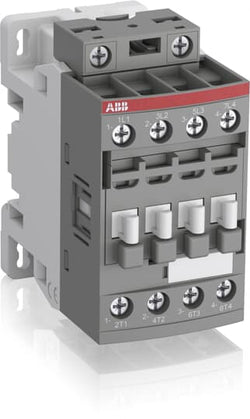
2
2
0
0
4P
IEC/EN 60947-1, IEC/EN 60947-4-1, UL 60335-2-40 LZGH2 A2L, UL 60947-1, UL 60947-4-1, CSA C22.2 No. 60335-2-40 LZGH2 A2L, CAN/CSA C22.2 No.60947-1, CAN/CSA C22.2 No.60947-4-1
Main Circuit 690 V
Control Circuit 50 / 60 Hz
Main Circuit 50 / 60 Hz
Control Circuit 50 / 60 Hz
Main Circuit 50 / 60 Hz
acc. to IEC 60947-4-1, Open Contactors Θ = 40 °C 35 A
(690 V) 40 °C 30 A
(690 V) 60 °C 30 A
(690 V) 70 °C 26 A
(690 V) 40 °C 30 A
(690 V) 60 °C 30 A
(690 V) 70 °C 26 A
(415 V) 60 °C 18 A
(440 V) 60 °C 18 A
(500 V) 60 °C 15 A
(690 V) 60 °C 10.5 A
(380 / 400 V) 60 °C 18 A
(220 / 230 / 240 V) 60 °C 18 A
(415 V) 60 °C 18 A
(440 V) 60 °C 18 A
(500 V) 60 °C 15 A
(690 V) 60 °C 10.5 A
(380 / 400 V) 60 °C 18 A
(220 / 230 / 240 V) 60 °C 18 A
(400 V) 7.5 kW
(415 V) 9 kW
(440 V) 9 kW
(500 V) 9 kW
(690 V) 9 kW
(380 / 400 V) 7.5 kW
(220 / 230 / 240 V) 4 kW
(400 V) 7.5 kW
(415 V) 9 kW
(440 V) 9 kW
(500 V) 9 kW
(690 V) 9 kW
(380 / 400 V) 7.5 kW
(220 / 230 / 240 V) 4 kW
at 40 °C Ambient Temp, in Free Air, from a Cold State 10 s 150 A
at 40 °C Ambient Temp, in Free Air, from a Cold State 15 min 35 A
at 40 °C Ambient Temp, in Free Air, from a Cold State 1 min 60 A
at 40 °C Ambient Temp, in Free Air, from a Cold State 1 s 300 A
at 40 °C Ambient Temp, in Free Air, from a Cold State 30 s 80 A
cos phi=0.45 (cos phi=0.35 for Ie > 100 A) at 440 V 250 A
cos phi=0.45 (cos phi=0.35 for Ie > 100 A) at 690 V 106 A
cos phi=0.45 (cos phi=0.35 for Ie > 100 A) at 440 V 250 A
cos phi=0.45 (cos phi=0.35 for Ie > 100 A) at 690 V 106 A
acc. to IEC 60947-4-1 690 V
acc. to UL/CSA 600 V
acc. to IEC 60947-4-1 690 V
acc. to UL/CSA 600 V
6 kV
(AC-1) 600 cycles per hour
3600 cycles per hour
50 Hz 100 ... 250 V
60 Hz 100 ... 250 V
DC Operation 100 ... 250 V
50 Hz 100 ... 250 V
60 Hz 100 ... 250 V
DC Operation 100 ... 250 V
at Rated Operating Conditions AC-1 per Pole 1.2 W
at Rated Operating Conditions AC-3 per Pole 0.35 W
at Rated Operating Conditions AC-1 per Pole 1.2 W
at Rated Operating Conditions AC-3 per Pole 0.35 W
Between Coil De-energization and NC Contact Closing 13 ... 98 ms
Between Coil De-energization and NO Contact Opening 11 ... 95 ms
Between Coil Energization and NC Contact Opening 38 ... 90 ms
Between Coil Energization and NO Contact Closing 40 ... 95 ms
Between Coil De-energization and NC Contact Closing 13 ... 98 ms
Between Coil De-energization and NO Contact Opening 11 ... 95 ms
Between Coil Energization and NC Contact Opening 38 ... 90 ms
Between Coil Energization and NO Contact Closing 40 ... 95 ms
TH35-15 (35 x 15 mm Mounting Rail) acc. to IEC 60715
TH35-7.5 (35 x 7.5 mm Mounting Rail) acc. to IEC 60715
TH35-15 (35 x 15 mm Mounting Rail) acc. to IEC 60715
TH35-7.5 (35 x 7.5 mm Mounting Rail) acc. to IEC 60715
2 x M4 Screws Placed Diagonally
Flexible with Ferrule 1/2x 0.75 ... 6 mm²
Flexible with Insulated Ferrule 1x 0.75 ... 4 mm²
Flexible with Insulated Ferrule 2x 0.75 ... 2.5 mm²
Rigid Solid 1/2x 1 ... 4 mm²
Rigid Stranded 1/2x 1 ... 6 mm²
Flexible with Ferrule 1/2x 0.75 ... 6 mm²
Flexible with Insulated Ferrule 1x 0.75 ... 4 mm²
Flexible with Insulated Ferrule 2x 0.75 ... 2.5 mm²
Rigid Solid 1/2x 1 ... 4 mm²
Rigid Stranded 1/2x 1 ... 6 mm²
Rigid Solid 1/2x 1 ... 2.5 mm²
Rigid Stranded 1/2x 1 ... 2.5 mm²
Rigid Solid 1/2x 1 ... 2.5 mm²
Rigid Stranded 1/2x 1 ... 2.5 mm²
Flexible with Ferrule 1/2x 0.75 ... 2.5 mm²
Flexible with Insulated Ferrule 1x 0.75 ... 2.5 mm²
Flexible with Insulated Ferrule 2x 0.75 ... 1.5 mm²
Rigid Solid 1/2x 1 ... 2.5 mm²
Rigid Stranded 1/2x 1 ... 2.5 mm²
Flexible with Ferrule 1/2x 0.75 ... 2.5 mm²
Flexible with Insulated Ferrule 1x 0.75 ... 2.5 mm²
Flexible with Insulated Ferrule 2x 0.75 ... 1.5 mm²
Rigid Solid 1/2x 1 ... 2.5 mm²
Rigid Stranded 1/2x 1 ... 2.5 mm²
Control Circuit 10 mm
Main Circuit 10 mm
Control Circuit 10 mm
Main Circuit 10 mm
acc. to IEC 60529, IEC 60947-1, EN 60529 Coil Terminals IP20
acc. to IEC 60529, IEC 60947-1, EN 60529 Main Terminals IP20
acc. to IEC 60529, IEC 60947-1, EN 60529 Coil Terminals IP20
acc. to IEC 60529, IEC 60947-1, EN 60529 Main Terminals IP20
Control Circuit 1.2 N·m
Main Circuit 1.5 N·m
Control Circuit 1.2 N·m
Main Circuit 1.5 N·m
Screw Terminals
Block Contactor
Technical UL/CSA
Main Circuit 600 V
(600 V AC) 30 A
Rigid Solid 1/2x 16-10 AWG
Rigid Stranded 1/2x 16-10 AWG
Rigid Solid 1/2x 16-10 AWG
Rigid Stranded 1/2x 16-10 AWG
Rigid Solid 1/2x 18-14 AWG
Rigid Stranded 1/2x 18-14 AWG
Rigid Solid 1/2x 18-14 AWG
Rigid Stranded 1/2x 18-14 AWG
Rigid Solid 1/2x 18-14 AWG
Rigid Stranded 1/2x 18-14 AWG
Rigid Solid 1/2x 18-14 AWG
Rigid Stranded 1/2x 18-14 AWG
Control Circuit 11 in·lb
Main Circuit 13 in·lb
Control Circuit 11 in·lb
Main Circuit 13 in·lb
Environmental
Close to Contactor for Storage -60 ... +80 °C
Near Contactor for Operation in Free Air -40 ... 70 °C
Close to Contactor for Storage -60 ... +80 °C
Near Contactor for Operation in Free Air -40 ... 70 °C
Category B according to IEC 60947-1 Annex Q
Without Derating 3000 m
Closed, Shock Direction: B1 25 g
Open, Shock Direction: B1 5 g
Shock Direction: A 30 g
Shock Direction: B2 15 g
Shock Direction: C1 25 g
Shock Direction: C2 25 g
Closed, Shock Direction: B1 25 g
Open, Shock Direction: B1 5 g
Shock Direction: A 30 g
Shock Direction: B2 15 g
Shock Direction: C1 25 g
Shock Direction: C2 25 g
4g Closed Position & 2g Open position 5 ... 300 Hz
3
Material Compliance
Following EU Directive 2011/65/EU and Amendment 2015/863 July 22, 2019
83466862-a48a-4256-9e40-a34ec37345f8 China
Business To Business
5. Small Equipment (No External Dimension More Than 50 cm)
ABB EcoSolutions
Recycled Cardboard - 86 %
Recycled Metal - 28 %
Certificates and Declarations
Container Information
box 1 piece
87 mm
79 mm
47 mm
0.31 kg
3471523116733
box 27 piece
250 mm
300 mm
315 mm
16.74 kg
External Classifications and Standards
Q
EC000066 - Power contactor, AC switching
EC000066 - Power contactor, AC switching
EC000066 - Power contactor, AC switching
V11.0 : 27371003
39121529
4758 >> Iec Contactors
3706356

Ordering
1 piece
85362010
Popular Downloads
Dimensions
45 mm
90 mm
86.75 mm
0.265 kg
Technical
(230 V AC) 100 kA
(250 V DC) 3 Poles in Series 10 kA
(400 V AC) 100 kA
(440 V AC) 30 kA
(500 V AC) 20 kA
(690 V AC) 3 kA
(230 V AC) 100 kA
(250 V DC) 3 Poles in Series 10 kA
(400 V AC) 100 kA
(440 V AC) 30 kA
(500 V AC) 20 kA
(690 V AC) 3 kA
(230 V AC) 100 kA
(400 V AC) 100 kA
(440 V AC) 30 kA
(500 V AC) 20 kA
(690 V AC) 3 kA
(230 V AC) 100 kA
(400 V AC) 100 kA
(440 V AC) 30 kA
(500 V AC) 20 kA
(690 V AC) 3 kA
50 A
2.5 ... 4.0 A
(400 V) Three Phase 1.5 kW
(400 V) Three Phase 1.5 kW
Main Circuit 690 V AC
Main Circuit 250 V DC
Main Circuit 690 V AC
Main Circuit 250 V DC
4 A
4 A
4 A
4 A
Main Circuit 50 Hz
Main Circuit 60 Hz
Main Circuit 50 Hz
Main Circuit 60 Hz
0 ... 400 Hz
Main Circuit 6 kV
690 V
at Rated Operating Conditions per Pole 0.7 ... 1.8 W
3P
Main Circuit 4 A
Housing IP20
Main Circuit Terminals IP10
Housing IP20
Main Circuit Terminals IP10
3
50000 cycle
Nr. Operations 100000 cycle
Screw Terminals
Flexible with Ferrule 1/2x 0.75 ... 2.5 mm²
Flexible with Insulated Ferrule 1/2x 0.75 ... 2.5 mm²
Flexible 1/2x 0.75 ... 2.5 mm²
Rigid 1/2x 1 ... 4 mm²
Flexible with Ferrule 1/2x 0.75 ... 2.5 mm²
Flexible with Insulated Ferrule 1/2x 0.75 ... 2.5 mm²
Flexible 1/2x 0.75 ... 2.5 mm²
Rigid 1/2x 1 ... 4 mm²
Main Circuit 0.8 ... 1.2 N·m
Main Circuit 9 mm
Pozidriv 2
1 ... 6
TH35-15 (35 x 15 mm Mounting Rail) acc. to IEC 60715
TH35-7.5 (35 x 7.5 mm Mounting Rail) acc. to IEC 60715
TH35-15 (35 x 15 mm Mounting Rail) acc. to IEC 60715
TH35-7.5 (35 x 7.5 mm Mounting Rail) acc. to IEC 60715
Electrical Conductive Board, Horizontal - Up to 400 V 0 mm
Electrical Conductive Board, Horizontal - Up to 690 V 1.5 mm
Electrical Conductive Board, Vertical 75 mm
Other Device Same Type, Horizontal 0 mm
Other Device Same Type, Vertical 150 mm
Electrical Conductive Board, Horizontal - Up to 400 V 0 mm
Electrical Conductive Board, Horizontal - Up to 690 V 1.5 mm
Electrical Conductive Board, Vertical 75 mm
Other Device Same Type, Horizontal 0 mm
Other Device Same Type, Vertical 150 mm
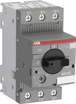
Rotary Handle
ON / OFF / TRIP
IEC/EN 60947-1
IEC/EN 60947-2
IEC/EN 60947-4-1
UL 60947-1
UL 60947-4-1
IEC 60335-2-40 A2L
IEC/EN 60947-1
IEC/EN 60947-2
IEC/EN 60947-4-1
UL 60947-1
UL 60947-4-1
IEC 60335-2-40 A2L
UL508 Self-Protected Combination Motor Controller (Type E) in combination with feeder block S1-M3-xx
Technical UL/CSA
Manual Self-Protected Combination Controllers (Type E), (480Y / 277 V AC) 65 kA
Manual Self-Protected Combination Controllers (Type E), (600Y / 347 V AC) 47 kA
Any UL Listed Fuses or Circuit-Breakers, Group Installations (480 V AC) 65 kA
Any UL Listed Fuses or Circuit-Breakers, Group Installations (600 V AC) 47 kA
Any UL Listed Fuses or Circuit-Breakers, Motor Disconnect (480 V AC) 65 kA
Any UL Listed Fuses or Circuit-Breakers, Motor Disconnect (600 V AC) 47 kA
Any UL Listed Fuses or Circuit-Breakers, Tap Conductor Protection in Group Installations (480Y / 277 V AC) 65 kA
Any UL Listed Fuses or Circuit-Breakers, Tap Conductor Protection in Group Installations (600Y / 347 V AC) 47 kA
Main Circuit 600 V AC
(200 V AC) Three Phase 0.75 Hp
(208 V AC) Three Phase 0.75 Hp
(220 ... 240 V AC) Three Phase 1 Hp
(440 ... 480 V AC) Three Phase 2 Hp
(550 ... 600 V AC) Three Phase 3 Hp
(200 V AC) Three Phase 0.75 Hp
(208 V AC) Three Phase 0.75 Hp
(220 ... 240 V AC) Three Phase 1 Hp
(440 ... 480 V AC) Three Phase 2 Hp
(550 ... 600 V AC) Three Phase 3 Hp
(200 V AC) Three Phase 4 A
(208 V AC) Three Phase 4 A
(220 ... 240 V AC) Three Phase 4 A
(440 ... 480 V AC) Three Phase 4 A
(550 ... 600 V AC) Three Phase 3.9 A
(200 V AC) Three Phase 4 A
(208 V AC) Three Phase 4 A
(220 ... 240 V AC) Three Phase 4 A
(440 ... 480 V AC) Three Phase 4 A
(550 ... 600 V AC) Three Phase 3.9 A
(200 V AC) Three Phase 24 A
(208 V AC) Three Phase 24 A
(220 ... 240 V AC) Three Phase 24 A
(440 ... 480 V AC) Three Phase 24 A
(550 ... 600 V AC) Three Phase 25.6 A
(200 V AC) Three Phase 24 A
(208 V AC) Three Phase 24 A
(220 ... 240 V AC) Three Phase 24 A
(440 ... 480 V AC) Three Phase 24 A
(550 ... 600 V AC) Three Phase 25.6 A
(600 V AC) 4 A
Flexible 1/2x 16-12 AWG
Stranded 1/2x 16-12 AWG
Flexible 1/2x 16-12 AWG
Stranded 1/2x 16-12 AWG
Main Circuit 10 ... 12 in·lb
Environmental
Around the Enclosure 0 ... +40 °C
Operation -25 ... +70 °C
Operation Compensated -25 ... +60 °C
Storage -50 ... +80 °C
Around the Enclosure 0 ... +40 °C
Operation -25 ... +70 °C
Operation Compensated -25 ... +60 °C
Storage -50 ... +80 °C
Yes
2000 m
11 ms Pulse 25g
5g 3 ... 150 Hz
Material Compliance
Following EU Directive 2011/65/EU and Amendment 2015/863 July 22, 2019
Business To Business
5. Small Equipment (No External Dimension More Than 50 cm)
ABB EcoSolutions
Certificates and Declarations
Container Information
box 1 piece
92 mm
95 mm
50 mm
0.28 kg
4013614400087
carton 40 piece
280 mm
395 mm
210 mm
11.586 kg
4013614408984
External Classifications and Standards
F
EC000074 - Motor protection circuit-breaker
EC000074 - Motor protection circuit-breaker
V11.0 : 27370401
39121521
4731 >> Manual Starters
3705992
4364077
3112124
Ordering
1 piece
85364900
Popular Downloads
Dimensions
45 mm
77 mm
86 mm
0.31 kg
Technical
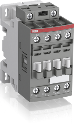
4
0
0
0
4P
IEC/EN 60947-1, IEC/EN 60947-4-1, UL 60335-2-40 LZGH2 A2L, UL 60947-1, UL 60947-4-1, CSA C22.2 No. 60335-2-40 LZGH2 A2L, CAN/CSA C22.2 No.60947-1, CAN/CSA C22.2 No.60947-4-1
Main Circuit 690 V
Control Circuit 50 / 60 Hz
Main Circuit 50 / 60 Hz
Control Circuit 50 / 60 Hz
Main Circuit 50 / 60 Hz
acc. to IEC 60947-4-1, Open Contactors Θ = 40 °C 35 A
(690 V) 40 °C 30 A
(690 V) 60 °C 30 A
(690 V) 70 °C 26 A
(690 V) 40 °C 30 A
(690 V) 60 °C 30 A
(690 V) 70 °C 26 A
(415 V) 60 °C 18 A
(440 V) 60 °C 18 A
(500 V) 60 °C 15 A
(690 V) 60 °C 10.5 A
(380 / 400 V) 60 °C 18 A
(220 / 230 / 240 V) 60 °C 18 A
(415 V) 60 °C 18 A
(440 V) 60 °C 18 A
(500 V) 60 °C 15 A
(690 V) 60 °C 10.5 A
(380 / 400 V) 60 °C 18 A
(220 / 230 / 240 V) 60 °C 18 A
(110 V) 1-Pole, 40 °C 20 A
(110 V) 1-Pole, 60 °C 20 A
(110 V) 1-Pole, 70 °C 20 A
(110 V) 2 Poles in Series, 40 °C 30 A
(110 V) 2 Poles in Series, 60 °C 30 A
(110 V) 2 Poles in Series, 70 °C 26 A
(110 V) 3 Poles in Series, 40 °C 30 A
(110 V) 3 Poles in Series, 60 °C 30 A
(110 V) 3 Poles in Series, 70 °C 26 A
(110 V) 4 Poles in Series, 40 °C 30 A
(110 V) 4 Poles in Series, 60 °C 30 A
(110 V) 4 Poles in Series, 70 °C 26 A
(220 V) 2 Poles in Series, 40 °C 20 A
(220 V) 2 Poles in Series, 60 °C 20 A
(220 V) 2 Poles in Series, 70 °C 20 A
(220 V) 3 Poles in Series, 40 °C 30 A
(220 V) 3 Poles in Series, 60 °C 30 A
(220 V) 3 Poles in Series, 70 °C 26 A
(220 V) 4 Poles in Series, 40 °C 30 A
(220 V) 4 Poles in Series, 60 °C 30 A
(220 V) 4 Poles in Series, 70 °C 26 A
(440 V) 4 Poles in Series, 40 °C 20 A
(440 V) 4 Poles in Series, 60 °C 20 A
(440 V) 4 Poles in Series, 70 °C 20 A
(72 V) 1-Pole, 40 °C 30 A
(72 V) 1-Pole, 60 °C 30 A
(72 V) 1-Pole, 70 °C 26 A
(72 V) 2 Poles in Series, 40 °C 30 A
(72 V) 2 Poles in Series, 60 °C 30 A
(72 V) 2 Poles in Series, 70 °C 26 A
(72 V) 3 Poles in Series, 40 °C 30 A
(72 V) 3 Poles in Series, 60 °C 30 A
(72 V) 3 Poles in Series, 70 °C 26 A
(72 V) 4 Poles in Series, 40 °C 30 A
(72 V) 4 Poles in Series, 60 °C 30 A
(72 V) 4 Poles in Series, 70 °C 26 A
(110 V) 1-Pole, 40 °C 20 A
(110 V) 1-Pole, 60 °C 20 A
(110 V) 1-Pole, 70 °C 20 A
(110 V) 2 Poles in Series, 40 °C 30 A
(110 V) 2 Poles in Series, 60 °C 30 A
(110 V) 2 Poles in Series, 70 °C 26 A
(110 V) 3 Poles in Series, 40 °C 30 A
(110 V) 3 Poles in Series, 60 °C 30 A
(110 V) 3 Poles in Series, 70 °C 26 A
(110 V) 4 Poles in Series, 40 °C 30 A
(110 V) 1-Pole, 40 °C 8 A
(110 V) 1-Pole, 60 °C 8 A
(110 V) 1-Pole, 70 °C 8 A
(110 V) 2 Poles in Series, 40 °C 30 A
(110 V) 2 Poles in Series, 60 °C 30 A
(110 V) 2 Poles in Series, 70 °C 26 A
(110 V) 3 Poles in Series, 40 °C 30 A
(110 V) 3 Poles in Series, 60 °C 30 A
(110 V) 3 Poles in Series, 70 °C 26 A
(110 V) 4 Poles in Series, 40 °C 30 A
(110 V) 4 Poles in Series, 60 °C 30 A
(110 V) 4 Poles in Series, 70 °C 26 A
(220 V) 2 Poles in Series, 40 °C 8 A
(220 V) 2 Poles in Series, 60 °C 8 A
(220 V) 2 Poles in Series, 70 °C 8 A
(220 V) 3 Poles in Series, 40 °C 30 A
(220 V) 3 Poles in Series, 60 °C 30 A
(220 V) 3 Poles in Series, 70 °C 26 A
(220 V) 4 Poles in Series, 40 °C 30 A
(220 V) 4 Poles in Series, 60 °C 30 A
(220 V) 4 Poles in Series, 70 °C 26 A
(440 V) 4 Poles in Series, 40 °C 8 A
(440 V) 4 Poles in Series, 60 °C 8 A
(440 V) 4 Poles in Series, 70 °C 8 A
(72 V) 1-Pole, 40 °C 30 A
(72 V) 1-Pole, 60 °C 30 A
(72 V) 1-Pole, 70 °C 26 A
(72 V) 2 Poles in Series, 40 °C 30 A
(72 V) 2 Poles in Series, 60 °C 30 A
(72 V) 2 Poles in Series, 70 °C 26 A
(72 V) 3 Poles in Series, 40 °C 30 A
(72 V) 3 Poles in Series, 60 °C 30 A
(72 V) 3 Poles in Series, 70 °C 26 A
(72 V) 4 Poles in Series, 40 °C 30 A
(72 V) 4 Poles in Series, 60 °C 30 A
(72 V) 4 Poles in Series, 70 °C 26 A
(110 V) 1-Pole, 40 °C 8 A
(110 V) 1-Pole, 60 °C 8 A
(110 V) 1-Pole, 70 °C 8 A
(110 V) 2 Poles in Series, 40 °C 30 A
(110 V) 2 Poles in Series, 60 °C 30 A
(110 V) 2 Poles in Series, 70 °C 26 A
(110 V) 3 Poles in Series, 40 °C 30 A
(110 V) 3 Poles in Series, 60 °C 30 A
(110 V) 3 Poles in Series, 70 °C 26 A
(110 V) 4 Poles in Series, 40 °C 30 A
(110 V) 1-Pole, 40 °C 4 A
(110 V) 1-Pole, 60 °C 4 A
(110 V) 1-Pole, 70 °C 4 A
(110 V) 2 Poles in Series, 40 °C 20 A
(110 V) 2 Poles in Series, 60 °C 20 A
(110 V) 2 Poles in Series, 70 °C 20 A
(110 V) 3 Poles in Series, 40 °C 30 A
(110 V) 3 Poles in Series, 60 °C 30 A
(110 V) 3 Poles in Series, 70 °C 26 A
(110 V) 4 Poles in Series, 40 °C 30 A
(110 V) 4 Poles in Series, 60 °C 30 A
(110 V) 4 Poles in Series, 70 °C 26 A
(220 V) 2 Poles in Series, 40 °C 4 A
(220 V) 2 Poles in Series, 60 °C 4 A
(220 V) 2 Poles in Series, 70 °C 4 A
(220 V) 3 Poles in Series, 40 °C 16 A
(220 V) 3 Poles in Series, 60 °C 16 A
(220 V) 3 Poles in Series, 70 °C 16 A
(220 V) 4 Poles in Series, 40 °C 20 A
(220 V) 4 Poles in Series, 60 °C 20 A
(220 V) 4 Poles in Series, 70 °C 20 A
(440 V) 4 Poles in Series, 40 °C 4 A
(440 V) 4 Poles in Series, 60 °C 4 A
(440 V) 4 Poles in Series, 70 °C 4 A
(72 V) 1-Pole, 40 °C 16 A
(72 V) 1-Pole, 60 °C 16 A
(72 V) 1-Pole, 70 °C 16 A
(72 V) 2 Poles in Series, 40 °C 30 A
(72 V) 2 Poles in Series, 60 °C 30 A
(72 V) 2 Poles in Series, 70 °C 26 A
(72 V) 3 Poles in Series, 40 °C 30 A
(72 V) 3 Poles in Series, 60 °C 30 A
(72 V) 3 Poles in Series, 70 °C 26 A
(72 V) 4 Poles in Series, 40 °C 30 A
(72 V) 4 Poles in Series, 60 °C 30 A
(72 V) 4 Poles in Series, 70 °C 26 A
(110 V) 1-Pole, 40 °C 4 A
(110 V) 1-Pole, 60 °C 4 A
(110 V) 1-Pole, 70 °C 4 A
(110 V) 2 Poles in Series, 40 °C 20 A
(110 V) 2 Poles in Series, 60 °C 20 A
(110 V) 2 Poles in Series, 70 °C 20 A
(110 V) 3 Poles in Series, 40 °C 30 A
(110 V) 3 Poles in Series, 60 °C 30 A
(110 V) 3 Poles in Series, 70 °C 26 A
(110 V) 4 Poles in Series, 40 °C 30 A
(400 V) 7.5 kW
(415 V) 9 kW
(440 V) 9 kW
(500 V) 9 kW
(690 V) 9 kW
(380 / 400 V) 7.5 kW
(220 / 230 / 240 V) 4 kW
(400 V) 7.5 kW
(415 V) 9 kW
(440 V) 9 kW
(500 V) 9 kW
(690 V) 9 kW
(380 / 400 V) 7.5 kW
(220 / 230 / 240 V) 4 kW
at 40 °C Ambient Temp, in Free Air, from a Cold State 10 s 150 A
at 40 °C Ambient Temp, in Free Air, from a Cold State 15 min 35 A
at 40 °C Ambient Temp, in Free Air, from a Cold State 1 min 60 A
at 40 °C Ambient Temp, in Free Air, from a Cold State 1 s 300 A
at 40 °C Ambient Temp, in Free Air, from a Cold State 30 s 80 A
cos phi=0.45 (cos phi=0.35 for Ie > 100 A) at 440 V 250 A
cos phi=0.45 (cos phi=0.35 for Ie > 100 A) at 690 V 106 A
cos phi=0.45 (cos phi=0.35 for Ie > 100 A) at 440 V 250 A
cos phi=0.45 (cos phi=0.35 for Ie > 100 A) at 690 V 106 A
acc. to IEC 60947-4-1 690 V
acc. to UL/CSA 600 V
acc. to IEC 60947-4-1 690 V
acc. to UL/CSA 600 V
6 kV
(AC-1) 600 cycles per hour
3600 cycles per hour
50 Hz 250 ... 500 V
60 Hz 250 ... 500 V
DC Operation 250 ... 500 V
50 Hz 250 ... 500 V
60 Hz 250 ... 500 V
DC Operation 250 ... 500 V
at Rated Operating Conditions AC-1 per Pole 1.2 W
at Rated Operating Conditions AC-3 per Pole 0.35 W
at Rated Operating Conditions AC-1 per Pole 1.2 W
at Rated Operating Conditions AC-3 per Pole 0.35 W
Between Coil De-energization and NC Contact Closing 13 ... 98 ms
Between Coil De-energization and NO Contact Opening 11 ... 95 ms
Between Coil Energization and NC Contact Opening 38 ... 90 ms
Between Coil Energization and NO Contact Closing 40 ... 95 ms
Between Coil De-energization and NC Contact Closing 13 ... 98 ms
Between Coil De-energization and NO Contact Opening 11 ... 95 ms
Between Coil Energization and NC Contact Opening 38 ... 90 ms
Between Coil Energization and NO Contact Closing 40 ... 95 ms
TH35-15 (35 x 15 mm Mounting Rail) acc. to IEC 60715
TH35-7.5 (35 x 7.5 mm Mounting Rail) acc. to IEC 60715
TH35-15 (35 x 15 mm Mounting Rail) acc. to IEC 60715
TH35-7.5 (35 x 7.5 mm Mounting Rail) acc. to IEC 60715
2 x M4 Screws Placed Diagonally
Flexible with Ferrule 1/2x 0.75 ... 6 mm²
Flexible with Insulated Ferrule 1x 0.75 ... 4 mm²
Flexible with Insulated Ferrule 2x 0.75 ... 2.5 mm²
Rigid Solid 1/2x 1 ... 4 mm²
Rigid Stranded 1/2x 1 ... 6 mm²
Flexible with Ferrule 1/2x 0.75 ... 6 mm²
Flexible with Insulated Ferrule 1x 0.75 ... 4 mm²
Flexible with Insulated Ferrule 2x 0.75 ... 2.5 mm²
Rigid Solid 1/2x 1 ... 4 mm²
Rigid Stranded 1/2x 1 ... 6 mm²
Rigid Solid 1/2x 1 ... 2.5 mm²
Rigid Stranded 1/2x 1 ... 2.5 mm²
Rigid Solid 1/2x 1 ... 2.5 mm²
Rigid Stranded 1/2x 1 ... 2.5 mm²
Flexible with Ferrule 1/2x 0.75 ... 2.5 mm²
Flexible with Insulated Ferrule 1x 0.75 ... 2.5 mm²
Flexible with Insulated Ferrule 2x 0.75 ... 1.5 mm²
Rigid Solid 1/2x 1 ... 2.5 mm²
Rigid Stranded 1/2x 1 ... 2.5 mm²
Flexible with Ferrule 1/2x 0.75 ... 2.5 mm²
Flexible with Insulated Ferrule 1x 0.75 ... 2.5 mm²
Flexible with Insulated Ferrule 2x 0.75 ... 1.5 mm²
Rigid Solid 1/2x 1 ... 2.5 mm²
Rigid Stranded 1/2x 1 ... 2.5 mm²
Control Circuit 10 mm
Main Circuit 10 mm
Control Circuit 10 mm
Main Circuit 10 mm
acc. to IEC 60529, IEC 60947-1, EN 60529 Coil Terminals IP20
acc. to IEC 60529, IEC 60947-1, EN 60529 Main Terminals IP20
acc. to IEC 60529, IEC 60947-1, EN 60529 Coil Terminals IP20
acc. to IEC 60529, IEC 60947-1, EN 60529 Main Terminals IP20
Control Circuit 1.2 N·m
Main Circuit 1.5 N·m
Control Circuit 1.2 N·m
Main Circuit 1.5 N·m
Screw Terminals
Block Contactor
Technical UL/CSA
Main Circuit 600 V
(600 V AC) 30 A
Rigid Solid 1/2x 16-10 AWG
Rigid Stranded 1/2x 16-10 AWG
Rigid Solid 1/2x 16-10 AWG
Rigid Stranded 1/2x 16-10 AWG
Rigid Solid 1/2x 18-14 AWG
Rigid Stranded 1/2x 18-14 AWG
Rigid Solid 1/2x 18-14 AWG
Rigid Stranded 1/2x 18-14 AWG
Rigid Solid 1/2x 18-14 AWG
Rigid Stranded 1/2x 18-14 AWG
Rigid Solid 1/2x 18-14 AWG
Rigid Stranded 1/2x 18-14 AWG
Control Circuit 11 in·lb
Main Circuit 13 in·lb
Control Circuit 11 in·lb
Main Circuit 13 in·lb
Environmental
Close to Contactor for Storage -60 ... +80 °C
Near Contactor for Operation in Free Air -40 ... 70 °C
Close to Contactor for Storage -60 ... +80 °C
Near Contactor for Operation in Free Air -40 ... 70 °C
Category B according to IEC 60947-1 Annex Q
Without Derating 3000 m
Closed, Shock Direction: B1 25 g
Open, Shock Direction: B1 5 g
Shock Direction: A 30 g
Shock Direction: B2 15 g
Shock Direction: C1 25 g
Shock Direction: C2 25 g
Closed, Shock Direction: B1 25 g
Open, Shock Direction: B1 5 g
Shock Direction: A 30 g
Shock Direction: B2 15 g
Shock Direction: C1 25 g
Shock Direction: C2 25 g
4g Closed Position & 2g Open position 5 ... 300 Hz
3
Material Compliance
Following EU Directive 2011/65/EU and Amendment 2015/863 July 22, 2019
25f26f66-ff06-4d0c-8bd9-be4b2047aa12 China
8c96398a-4fec-4315-8c22-0c68273a2480 Poland
bf500311-99b6-4df1-91f3-a003f9876705 Hungary
33c68392-e54c-427b-a6e5-114e5cb59a6a Netherlands
448620f1-3549-46d2-b3ad-394f6cdb94c6 Greece
d2406be1-573a-4ef7-bb64-5881ad4e8fca Estonia
a79101b1-a14d-4db2-a55c-e174068e4786 Croatia
275d07ee-ef61-4f7b-883a-b7db0696644d Germany
3987a0aa-20d4-4ee1-a790-dd29f4817126 Germany
52d48375-07ae-425a-8c8e-91245506d667 Denmark
7a11ac3c-63e4-44ec-9fab-064eb304fd5a Sweden
29ed8001-5d64-48e4-bdb6-26b6e16ed18a Germany
d3f90c7e-d658-483d-b264-3c06c6a32fc3 Portugal
4d55654d-57c5-4f19-b252-f7bd4edeb99f Bulgaria
c1740ed7-2063-47af-961e-282af2c4edc0 France
19a3ac84-469c-4c16-b58a-7ad88fb2dea2 Poland
46c1f5c7-8d07-475a-a41c-b5e89191f962 Sweden
dde8e830-c0a4-4bc0-a4b6-2727a527cc26 Hungary
e5886f7e-474a-4758-8465-7440f004b2bf Belgium
8f68d79d-aa3d-401c-a141-11c928a64a06 France
b9fd48f6-81d8-4092-a290-360e48cc3ba4 Germany
d04ed4d2-0a48-44b5-bb6d-3f097964afd4 Norway
5354cb02-66d7-4c5e-9f6e-5e14409efe2a Czech Republic
9dbab882-ff67-421a-8d2e-6e0b4a51052e Poland
7d468d27-83b8-4253-8894-59d8280fcee3 Belgium
aa144837-74c4-47d4-8089-e743cfef6e02 Finland
9f6b6ecc-4d0a-4a31-99c0-3221a4658602 Germany
c4e4dea6-0954-46f9-ad5f-0eaf496e3a60 Spain
8c96398a-4fec-4315-8c22-0c68273a2480 Poland
bf500311-99b6-4df1-91f3-a003f9876705 Hungary
33c68392-e54c-427b-a6e5-114e5cb59a6a Netherlands
448620f1-3549-46d2-b3ad-394f6cdb94c6 Greece
d2406be1-573a-4ef7-bb64-5881ad4e8fca Estonia
a79101b1-a14d-4db2-a55c-e174068e4786 Croatia
275d07ee-ef61-4f7b-883a-b7db0696644d Germany
3987a0aa-20d4-4ee1-a790-dd29f4817126 Germany
52d48375-07ae-425a-8c8e-91245506d667 Denmark
7a11ac3c-63e4-44ec-9fab-064eb304fd5a Sweden
Business To Business
5. Small Equipment (No External Dimension More Than 50 cm)
ABB EcoSolutions
Recycled Cardboard - 86 %
Recycled Metal - 28 %
Certificates and Declarations
Container Information
box 1 piece
87 mm
79 mm
47 mm
0.31 kg
3471523115149
box 27 piece
250 mm
300 mm
315 mm
16.74 kg
External Classifications and Standards
Q
EC000066 - Power contactor, AC switching
EC000066 - Power contactor, AC switching
EC000066 - Power contactor, AC switching
V11.0 : 27371003
39121529
4758 >> Iec Contactors
3706338
3211399
Ordering
1 piece
85364900
Popular Downloads
Dimensions
45 mm
77 mm
86 mm
0.31 kg
Technical
3
0
0
1
3P
IEC/EN 60947-1, IEC/EN 60947-4-1, UL 60335-2-40 LZGH2 A2L, UL 60947-4-1, CSA C22.2 No. 60335-2-40 LZGH2 A2L, CSA C22.2 No. 60947-4-1
Auxiliary Circuit 690 V
Main Circuit 690 V
Auxiliary Circuit 690 V
Main Circuit 690 V
Auxiliary Circuit 50 / 60 Hz
Control Circuit 50 / 60 Hz
Main Circuit 50 / 60 Hz
Auxiliary Circuit 50 / 60 Hz
Control Circuit 50 / 60 Hz
Main Circuit 50 / 60 Hz
acc. to IEC 60947-4-1, Open Contactors Θ = 40 °C 35 A
acc. to IEC 60947-5-1, Θ = 40 °C 16 A
acc. to IEC 60947-4-1, Open Contactors Θ = 40 °C 35 A
acc. to IEC 60947-5-1, Θ = 40 °C 16 A
(690 V) 40 °C 30 A
(690 V) 60 °C 30 A
(690 V) 70 °C 26 A
(690 V) 40 °C 30 A
(690 V) 60 °C 30 A
(690 V) 70 °C 26 A
(415 V) 60 °C 18 A
(440 V) 60 °C 18 A
(500 V) 60 °C 15 A
(690 V) 60 °C 10.5 A
(380 / 400 V) 60 °C 18 A
(220 / 230 / 240 V) 60 °C 18 A
(415 V) 60 °C 18 A
(440 V) 60 °C 18 A
(500 V) 60 °C 15 A
(690 V) 60 °C 10.5 A
(380 / 400 V) 60 °C 18 A
(220 / 230 / 240 V) 60 °C 18 A
(415 V) 60 °C 18 A
(440 V) 60 °C 18 A
(500 V) 60 °C 15 A
(690 V) 60 °C 10.5 A
(380 / 400 V) 60 °C 18 A
(220 / 230 / 240 V) 60 °C 18 A
(415 V) 60 °C 18 A
(440 V) 60 °C 18 A
(500 V) 60 °C 15 A
(690 V) 60 °C 10.5 A
(380 / 400 V) 60 °C 18 A
(220 / 230 / 240 V) 60 °C 18 A
(500 V) 2 A
(690 V) 2 A
(24 / 127 V) 6 A
(220 / 240 V) 4 A
(400 / 440 V) 3 A
(500 V) 2 A
(690 V) 2 A
(24 / 127 V) 6 A
(220 / 240 V) 4 A
(400 / 440 V) 3 A
(110 V) 1-Pole, 40 °C 20 A
(110 V) 1-Pole, 60 °C 20 A
(110 V) 1-Pole, 70 °C 20 A
(110 V) 2 Poles in Series, 40 °C 30 A
(110 V) 2 Poles in Series, 60 °C 30 A
(110 V) 2 Poles in Series, 70 °C 26 A
(110 V) 3 Poles in Series, 40 °C 30 A
(110 V) 3 Poles in Series, 60 °C 30 A
(110 V) 3 Poles in Series, 70 °C 26 A
(220 V) 2 Poles in Series, 40 °C 20 A
(220 V) 2 Poles in Series, 60 °C 20 A
(220 V) 2 Poles in Series, 70 °C 20 A
(220 V) 3 Poles in Series, 40 °C 30 A
(220 V) 3 Poles in Series, 60 °C 30 A
(220 V) 3 Poles in Series, 70 °C 26 A
(72 V) 1-Pole, 40 °C 30 A
(72 V) 1-Pole, 60 °C 30 A
(72 V) 1-Pole, 70 °C 26 A
(72 V) 2 Poles in Series, 40 °C 30 A
(72 V) 2 Poles in Series, 60 °C 30 A
(72 V) 2 Poles in Series, 70 °C 26 A
(72 V) 3 Poles in Series, 40 °C 30 A
(72 V) 3 Poles in Series, 60 °C 30 A
(72 V) 3 Poles in Series, 70 °C 26 A
(110 V) 1-Pole, 40 °C 20 A
(110 V) 1-Pole, 60 °C 20 A
(110 V) 1-Pole, 70 °C 20 A
(110 V) 2 Poles in Series, 40 °C 30 A
(110 V) 2 Poles in Series, 60 °C 30 A
(110 V) 2 Poles in Series, 70 °C 26 A
(110 V) 3 Poles in Series, 40 °C 30 A
(110 V) 3 Poles in Series, 60 °C 30 A
(110 V) 3 Poles in Series, 70 °C 26 A
(220 V) 2 Poles in Series, 40 °C 20 A
(110 V) 1-Pole, 40 °C 8 A
(110 V) 1-Pole, 60 °C 8 A
(110 V) 1-Pole, 70 °C 8 A
(110 V) 2 Poles in Series, 40 °C 30 A
(110 V) 2 Poles in Series, 60 °C 30 A
(110 V) 2 Poles in Series, 70 °C 26 A
(110 V) 3 Poles in Series, 40 °C 30 A
(110 V) 3 Poles in Series, 60 °C 30 A
(110 V) 3 Poles in Series, 70 °C 26 A
(220 V) 2 Poles in Series, 40 °C 8 A
(220 V) 2 Poles in Series, 60 °C 8 A
(220 V) 2 Poles in Series, 70 °C 8 A
(220 V) 3 Poles in Series, 40 °C 30 A
(220 V) 3 Poles in Series, 60 °C 30 A
(220 V) 3 Poles in Series, 70 °C 26 A
(72 V) 1-Pole, 40 °C 30 A
(72 V) 1-Pole, 60 °C 30 A
(72 V) 1-Pole, 70 °C 26 A
(72 V) 2 Poles in Series, 40 °C 30 A
(72 V) 2 Poles in Series, 60 °C 30 A
(72 V) 2 Poles in Series, 70 °C 26 A
(72 V) 3 Poles in Series, 40 °C 30 A
(72 V) 3 Poles in Series, 60 °C 30 A
(72 V) 3 Poles in Series, 70 °C 26 A
(110 V) 1-Pole, 40 °C 8 A
(110 V) 1-Pole, 60 °C 8 A
(110 V) 1-Pole, 70 °C 8 A
(110 V) 2 Poles in Series, 40 °C 30 A
(110 V) 2 Poles in Series, 60 °C 30 A
(110 V) 2 Poles in Series, 70 °C 26 A
(110 V) 3 Poles in Series, 40 °C 30 A
(110 V) 3 Poles in Series, 60 °C 30 A
(110 V) 3 Poles in Series, 70 °C 26 A
(220 V) 2 Poles in Series, 40 °C 8 A
(110 V) 1-Pole, 40 °C 4 A
(110 V) 1-Pole, 60 °C 4 A
(110 V) 1-Pole, 70 °C 4 A
(110 V) 2 Poles in Series, 40 °C 20 A
(110 V) 2 Poles in Series, 60 °C 20 A
(110 V) 2 Poles in Series, 70 °C 20 A
(110 V) 3 Poles in Series, 40 °C 30 A
(110 V) 3 Poles in Series, 60 °C 30 A
(110 V) 3 Poles in Series, 70 °C 26 A
(220 V) 2 Poles in Series, 40 °C 4 A
(220 V) 2 Poles in Series, 60 °C 4 A
(220 V) 2 Poles in Series, 70 °C 4 A
(220 V) 3 Poles in Series, 40 °C 16 A
(220 V) 3 Poles in Series, 60 °C 16 A
(220 V) 3 Poles in Series, 70 °C 16 A
(72 V) 1-Pole, 40 °C 16 A
(72 V) 1-Pole, 60 °C 16 A
(72 V) 1-Pole, 70 °C 16 A
(72 V) 2 Poles in Series, 40 °C 30 A
(72 V) 2 Poles in Series, 60 °C 30 A
(72 V) 2 Poles in Series, 70 °C 26 A
(72 V) 3 Poles in Series, 40 °C 30 A
(72 V) 3 Poles in Series, 60 °C 30 A
(72 V) 3 Poles in Series, 70 °C 26 A
(110 V) 1-Pole, 40 °C 4 A
(110 V) 1-Pole, 60 °C 4 A
(110 V) 1-Pole, 70 °C 4 A
(110 V) 2 Poles in Series, 40 °C 20 A
(110 V) 2 Poles in Series, 60 °C 20 A
(110 V) 2 Poles in Series, 70 °C 20 A
(110 V) 3 Poles in Series, 40 °C 30 A
(110 V) 3 Poles in Series, 60 °C 30 A
(110 V) 3 Poles in Series, 70 °C 26 A
(220 V) 2 Poles in Series, 40 °C 4 A
(24 V) 6 A / 144 W
(48 V) 2.8 A / 134 W
(72 V) 1 A / 72 W
(110 V) 0.55 A / 60 W
(125 V) 0.55 A / 69 W
(220 V) 0.27 A / 60 W
(250 V) 0.27 A / 68 W
(400 V) 0.15 A / 60 W
(500 V) 0.13 A / 65 W
(600 V) 0.1 A / 60 W
(24 V) 6 A / 144 W
(48 V) 2.8 A / 134 W
(72 V) 1 A / 72 W
(110 V) 0.55 A / 60 W
(125 V) 0.55 A / 69 W
(220 V) 0.27 A / 60 W
(250 V) 0.27 A / 68 W
(400 V) 0.15 A / 60 W
(500 V) 0.13 A / 65 W
(600 V) 0.1 A / 60 W
(400 V) 7.5 kW
(415 V) 9 kW
(440 V) 9 kW
(500 V) 9 kW
(690 V) 9 kW
(380 / 400 V) 7.5 kW
(220 / 230 / 240 V) 4 kW
(400 V) 7.5 kW
(415 V) 9 kW
(440 V) 9 kW
(500 V) 9 kW
(690 V) 9 kW
(380 / 400 V) 7.5 kW
(220 / 230 / 240 V) 4 kW
(415 V) 9 kW
(440 V) 9 kW
(500 V) 9 kW
(690 V) 9 kW
(380 / 400 V) 7.5 kW
(220 / 230 / 240 V) 4 kW
(415 V) 9 kW
(440 V) 9 kW
(500 V) 9 kW
(690 V) 9 kW
(380 / 400 V) 7.5 kW
(220 / 230 / 240 V) 4 kW
at 40 °C Ambient Temp, in Free Air, from a Cold State 10 s 150 A
at 40 °C Ambient Temp, in Free Air, from a Cold State 15 min 35 A
at 40 °C Ambient Temp, in Free Air, from a Cold State 1 min 60 A
at 40 °C Ambient Temp, in Free Air, from a Cold State 1 s 300 A
at 40 °C Ambient Temp, in Free Air, from a Cold State 30 s 80 A
for 0.1 s 140 A
for 1 s 100 A
at 40 °C Ambient Temp, in Free Air, from a Cold State 10 s 150 A
at 40 °C Ambient Temp, in Free Air, from a Cold State 15 min 35 A
at 40 °C Ambient Temp, in Free Air, from a Cold State 1 min 60 A
at 40 °C Ambient Temp, in Free Air, from a Cold State 1 s 300 A
at 40 °C Ambient Temp, in Free Air, from a Cold State 30 s 80 A
for 0.1 s 140 A
for 1 s 100 A
cos phi=0.45 (cos phi=0.35 for Ie > 100 A) at 440 V 250 A
cos phi=0.45 (cos phi=0.35 for Ie > 100 A) at 690 V 106 A
cos phi=0.45 (cos phi=0.35 for Ie > 100 A) at 440 V 250 A
cos phi=0.45 (cos phi=0.35 for Ie > 100 A) at 690 V 106 A
acc. to IEC 60947-4-1 690 V
acc. to IEC 60947-5-1 690 V
acc. to UL/CSA 600 V
acc. to IEC 60947-4-1 690 V
acc. to IEC 60947-5-1 690 V
acc. to UL/CSA 600 V
6 kV
(AC-1) 600 cycles per hour
(AC-15) 1200 cycles per hour
(AC-2 / AC-4) 300 cycles per hour
(AC-3) 1200 cycles per hour
(DC-13) 900 cycles per hour
(AC-1) 600 cycles per hour
(AC-15) 1200 cycles per hour
(AC-2 / AC-4) 300 cycles per hour
(AC-3) 1200 cycles per hour
(DC-13) 900 cycles per hour
3600 cycles per hour
50 Hz 250 ... 500 V
60 Hz 250 ... 500 V
DC Operation 250 ... 500 V
50 Hz 250 ... 500 V
60 Hz 250 ... 500 V
DC Operation 250 ... 500 V
at 6 A per Pole 0.1 W
at Rated Operating Conditions AC-1 per Pole 1.2 W
at Rated Operating Conditions AC-3 per Pole 0.35 W
at 6 A per Pole 0.1 W
at Rated Operating Conditions AC-1 per Pole 1.2 W
at Rated Operating Conditions AC-3 per Pole 0.35 W
Between Coil De-energization and NC Contact Closing 13 ... 98 ms
Between Coil De-energization and NO Contact Opening 11 ... 95 ms
Between Coil Energization and NC Contact Opening 38 ... 90 ms
Between Coil Energization and NO Contact Closing 40 ... 95 ms
Between Coil De-energization and NC Contact Closing 13 ... 98 ms
Between Coil De-energization and NO Contact Opening 11 ... 95 ms
Between Coil Energization and NC Contact Opening 38 ... 90 ms
Between Coil Energization and NO Contact Closing 40 ... 95 ms
TH35-15 (35 x 15 mm Mounting Rail) acc. to IEC 60715
TH35-7.5 (35 x 7.5 mm Mounting Rail) acc. to IEC 60715
TH35-15 (35 x 15 mm Mounting Rail) acc. to IEC 60715
TH35-7.5 (35 x 7.5 mm Mounting Rail) acc. to IEC 60715
2 x M4 Screws Placed Diagonally
Flexible with Ferrule 1/2x 0.75 ... 6 mm²
Flexible with Insulated Ferrule 1x 0.75 ... 4 mm²
Flexible with Insulated Ferrule 2x 0.75 ... 2.5 mm²
Rigid Solid 1/2x 1 ... 4 mm²
Rigid Stranded 1/2x 1 ... 6 mm²
Flexible with Ferrule 1/2x 0.75 ... 6 mm²
Flexible with Insulated Ferrule 1x 0.75 ... 4 mm²
Flexible with Insulated Ferrule 2x 0.75 ... 2.5 mm²
Rigid Solid 1/2x 1 ... 4 mm²
Rigid Stranded 1/2x 1 ... 6 mm²
Flexible with Ferrule 1/2x 0.75 ... 2.5 mm²
Flexible with Insulated Ferrule 2x 0.75 ... 1.5 mm²
Flexible with Insulated Ferrule 1x 0.75 ... 2.5 mm²
Rigid Solid 1/2x 1 ... 2.5 mm²
Rigid Stranded 1/2x 1 ... 2.5 mm²
Flexible with Ferrule 1/2x 0.75 ... 2.5 mm²
Flexible with Insulated Ferrule 2x 0.75 ... 1.5 mm²
Flexible with Insulated Ferrule 1x 0.75 ... 2.5 mm²
Rigid Solid 1/2x 1 ... 2.5 mm²
Rigid Stranded 1/2x 1 ... 2.5 mm²
Flexible with Ferrule 1/2x 0.75 ... 2.5 mm²
Flexible with Insulated Ferrule 1x 0.75 ... 2.5 mm²
Flexible with Insulated Ferrule 2x 0.75 ... 1.5 mm²
Rigid Solid 1/2x 1 ... 2.5 mm²
Rigid Stranded 1/2x 1 ... 2.5 mm²
Flexible with Ferrule 1/2x 0.75 ... 2.5 mm²
Flexible with Insulated Ferrule 1x 0.75 ... 2.5 mm²
Flexible with Insulated Ferrule 2x 0.75 ... 1.5 mm²
Rigid Solid 1/2x 1 ... 2.5 mm²
Rigid Stranded 1/2x 1 ... 2.5 mm²
Auxiliary Circuit 10 mm
Control Circuit 10 mm
Main Circuit 10 mm
Auxiliary Circuit 10 mm
Control Circuit 10 mm
Main Circuit 10 mm
acc. to IEC 60529, IEC 60947-1, EN 60529 Auxiliary Terminals IP20
acc. to IEC 60529, IEC 60947-1, EN 60529 Coil Terminals IP20
acc. to IEC 60529, IEC 60947-1, EN 60529 Main Terminals IP20
acc. to IEC 60529, IEC 60947-1, EN 60529 Auxiliary Terminals IP20
acc. to IEC 60529, IEC 60947-1, EN 60529 Coil Terminals IP20
acc. to IEC 60529, IEC 60947-1, EN 60529 Main Terminals IP20
Auxiliary Circuit 1.2 N·m
Control Circuit 1.2 N·m
Main Circuit 1.5 N·m
Auxiliary Circuit 1.2 N·m
Control Circuit 1.2 N·m
Main Circuit 1.5 N·m
Screw Terminals
Block Contactor
Technical UL/CSA
Main Circuit 600 V
(600 V AC) 30 A
(120 V AC) Single Phase 1-1/2 hp
(200 ... 208 V AC) Three Phase 5 hp
(220 ... 240 V AC) Three Phase 5 hp
(240 V AC) Single Phase 3 hp
(440 ... 480 V AC) Three Phase 10 hp
(550 ... 600 V AC) Three Phase 15 hp
(120 V AC) Single Phase 1-1/2 hp
(200 ... 208 V AC) Three Phase 5 hp
(220 ... 240 V AC) Three Phase 5 hp
(240 V AC) Single Phase 3 hp
(440 ... 480 V AC) Three Phase 10 hp
(550 ... 600 V AC) Three Phase 15 hp
Rigid Solid 1/2x 16-10 AWG
Rigid Stranded 1/2x 16-10 AWG
Rigid Solid 1/2x 16-10 AWG
Rigid Stranded 1/2x 16-10 AWG
Rigid Solid 1/2x 18-14 AWG
Rigid Stranded 1/2x 18-14 AWG
Rigid Solid 1/2x 18-14 AWG
Rigid Stranded 1/2x 18-14 AWG
Rigid Solid 1/2x 18-14 AWG
Rigid Stranded 1/2x 18-14 AWG
Rigid Solid 1/2x 18-14 AWG
Rigid Stranded 1/2x 18-14 AWG
Auxiliary Circuit 11 in·lb
Control Circuit 11 in·lb
Main Circuit 13 in·lb
Auxiliary Circuit 11 in·lb
Control Circuit 11 in·lb
Main Circuit 13 in·lb
(120 V AC) Single Phase 20 A
(200 ... 208 V AC) Three Phase 17.5 A
(220 ... 240 V AC) Three Phase 15.2 A
(240 V AC) Single Phase 17 A
(440 ... 480 V AC) Three Phase 14 A
(550 ... 600 V AC) Three Phase 17 A
(120 V AC) Single Phase 20 A
(200 ... 208 V AC) Three Phase 17.5 A
(220 ... 240 V AC) Three Phase 15.2 A
(240 V AC) Single Phase 17 A
(440 ... 480 V AC) Three Phase 14 A
(550 ... 600 V AC) Three Phase 17 A
Environmental
Close to Contactor Fitted with Thermal O/L Relay -25 ... 60 °C
Close to Contactor without Thermal O/L Relay -40 ... 70 °C
Close to Contactor for Storage -60 ... +80 °C
Close to Contactor Fitted with Thermal O/L Relay -25 ... 60 °C
Close to Contactor without Thermal O/L Relay -40 ... 70 °C
Close to Contactor for Storage -60 ... +80 °C
Category B according to IEC 60947-1 Annex Q
Without Derating 3000 m
Closed, Shock Direction: B1 25 g
Open, Shock Direction: B1 5 g
Shock Direction: A 30 g
Shock Direction: B2 15 g
Shock Direction: C1 25 g
Shock Direction: C2 25 g
Closed, Shock Direction: B1 25 g
Open, Shock Direction: B1 5 g
Shock Direction: A 30 g
Shock Direction: B2 15 g
Shock Direction: C1 25 g
Shock Direction: C2 25 g
4g Closed Position & 2g Open position 5 ... 300 Hz
3
Material Compliance
Following EU Directive 2011/65/EU and Amendment 2015/863 July 22, 2019
68025695-965d-4cea-a138-abd9f6a581bc China
1827ab1d-cedb-4bc3-aad7-08ae312a223a Sweden
a6a45b81-b007-45c3-add1-aef10ea6dda3 Poland
f5627cca-12dd-4c54-9625-ace50cadbfc8 Portugal
bc67e1ff-e5d7-4cc4-a341-6d47f9972902 Bulgaria
9180cdd8-fa69-4bf5-9164-a421dd834117 Estonia
af61bbca-9ca7-4f4a-b7cf-6fc04e6c285e Hungary
a9b60459-ebfc-44fc-b02d-4ee7a9855709 Greece
40a8758a-6ee5-4520-8f87-3bb1d21ebe68 Netherlands
615564e5-0c01-4dcf-8ea8-9bc45137de3f Croatia
b34a1b3a-d4c5-4d92-a20c-491eec705154 Belgium
8856388c-fd55-4b9c-94b7-b47bb78b9b53 Germany
99b33f73-2bfa-4002-be96-dda2b5b9cc3e Denmark
201267cd-4137-413b-ad79-6ecaf16f3915 Germany
d33bfff1-bd44-4652-96bb-cfb66b357635 Spain
d9bec275-24e5-41e2-97d9-b3999cb298a4 Germany
828f7200-ea50-40d5-a8c9-6aefb0059697 Poland
7ae53756-c274-4f8b-8e3b-3b6df74197ca Poland
eef14ce1-f242-4713-aa33-23a61b77b38a France
6298a348-73b9-4870-b018-6fe55e292010 Belgium
0f987e5c-83a7-4e2e-8bb4-84064f96e98b Hungary
c250cded-e022-4e30-91db-09bdc931477d Germany
4b77b079-a4f9-4701-9042-e6bbe3a3b9f3 France
64052701-07ff-4637-b823-37f1b839dc02 Sweden
ff2651bc-730e-46fd-9c77-0a353ab52d61 Germany
eb01c1a3-603c-42d5-a88c-6ece909b6af5 Czech Republic
4c17bff8-76b6-421a-ba0e-c50ee7807c58 Norway
acd82cc6-41ab-48fe-a76d-01e314c47995 Finland
1827ab1d-cedb-4bc3-aad7-08ae312a223a Sweden
a6a45b81-b007-45c3-add1-aef10ea6dda3 Poland
f5627cca-12dd-4c54-9625-ace50cadbfc8 Portugal
bc67e1ff-e5d7-4cc4-a341-6d47f9972902 Bulgaria
9180cdd8-fa69-4bf5-9164-a421dd834117 Estonia
af61bbca-9ca7-4f4a-b7cf-6fc04e6c285e Hungary
a9b60459-ebfc-44fc-b02d-4ee7a9855709 Greece
40a8758a-6ee5-4520-8f87-3bb1d21ebe68 Netherlands
615564e5-0c01-4dcf-8ea8-9bc45137de3f Croatia
b34a1b3a-d4c5-4d92-a20c-491eec705154 Belgium
Business To Business
5. Small Equipment (No External Dimension More Than 50 cm)
ABB EcoSolutions
Recycled Cardboard - 86 %
Recycled Metal - 28 %
Certificates and Declarations
Container Information
box 1 piece
87 mm
79 mm
47 mm
0.31 kg
3471523110748
box 27 piece
250 mm
300 mm
315 mm
8.37 kg
External Classifications and Standards
Q
EC000066 - Power contactor, AC switching
EC000066 - Power contactor, AC switching
EC000066 - Power contactor, AC switching
V11.0 : 27371003
39121529
4758 >> Iec Contactors
3706247
3211375

Ordering
1 piece
85364900
Popular Downloads
Dimensions
45 mm
77 mm
86 mm
0.31 kg
Technical
2
2
0
0
4P
IEC/EN 60947-1, IEC/EN 60947-4-1, UL 60335-2-40 LZGH2 A2L, UL 60947-1, UL 60947-4-1, CSA C22.2 No. 60335-2-40 LZGH2 A2L, CAN/CSA C22.2 No.60947-1, CAN/CSA C22.2 No.60947-4-1
Main Circuit 690 V
Control Circuit 50 / 60 Hz
Main Circuit 50 / 60 Hz
Control Circuit 50 / 60 Hz
Main Circuit 50 / 60 Hz
acc. to IEC 60947-4-1, Open Contactors Θ = 40 °C 35 A
(690 V) 40 °C 30 A
(690 V) 60 °C 30 A
(690 V) 70 °C 26 A
(690 V) 40 °C 30 A
(690 V) 60 °C 30 A
(690 V) 70 °C 26 A
(415 V) 60 °C 18 A
(440 V) 60 °C 18 A
(500 V) 60 °C 15 A
(690 V) 60 °C 10.5 A
(380 / 400 V) 60 °C 18 A
(220 / 230 / 240 V) 60 °C 18 A
(415 V) 60 °C 18 A
(440 V) 60 °C 18 A
(500 V) 60 °C 15 A
(690 V) 60 °C 10.5 A
(380 / 400 V) 60 °C 18 A
(220 / 230 / 240 V) 60 °C 18 A
(400 V) 7.5 kW
(415 V) 9 kW
(440 V) 9 kW
(500 V) 9 kW
(690 V) 9 kW
(380 / 400 V) 7.5 kW
(220 / 230 / 240 V) 4 kW
(400 V) 7.5 kW
(415 V) 9 kW
(440 V) 9 kW
(500 V) 9 kW
(690 V) 9 kW
(380 / 400 V) 7.5 kW
(220 / 230 / 240 V) 4 kW
at 40 °C Ambient Temp, in Free Air, from a Cold State 10 s 150 A
at 40 °C Ambient Temp, in Free Air, from a Cold State 15 min 35 A
at 40 °C Ambient Temp, in Free Air, from a Cold State 1 min 60 A
at 40 °C Ambient Temp, in Free Air, from a Cold State 1 s 300 A
at 40 °C Ambient Temp, in Free Air, from a Cold State 30 s 80 A
cos phi=0.45 (cos phi=0.35 for Ie > 100 A) at 440 V 250 A
cos phi=0.45 (cos phi=0.35 for Ie > 100 A) at 690 V 106 A
cos phi=0.45 (cos phi=0.35 for Ie > 100 A) at 440 V 250 A
cos phi=0.45 (cos phi=0.35 for Ie > 100 A) at 690 V 106 A
acc. to IEC 60947-4-1 690 V
acc. to UL/CSA 600 V
acc. to IEC 60947-4-1 690 V
acc. to UL/CSA 600 V
6 kV
(AC-1) 600 cycles per hour
3600 cycles per hour
50 Hz 250 ... 500 V
60 Hz 250 ... 500 V
DC Operation 250 ... 500 V
50 Hz 250 ... 500 V
60 Hz 250 ... 500 V
DC Operation 250 ... 500 V
at Rated Operating Conditions AC-1 per Pole 1.2 W
at Rated Operating Conditions AC-3 per Pole 0.35 W
at Rated Operating Conditions AC-1 per Pole 1.2 W
at Rated Operating Conditions AC-3 per Pole 0.35 W
Between Coil De-energization and NC Contact Closing 13 ... 98 ms
Between Coil De-energization and NO Contact Opening 11 ... 95 ms
Between Coil Energization and NC Contact Opening 38 ... 90 ms
Between Coil Energization and NO Contact Closing 40 ... 95 ms
Between Coil De-energization and NC Contact Closing 13 ... 98 ms
Between Coil De-energization and NO Contact Opening 11 ... 95 ms
Between Coil Energization and NC Contact Opening 38 ... 90 ms
Between Coil Energization and NO Contact Closing 40 ... 95 ms
TH35-15 (35 x 15 mm Mounting Rail) acc. to IEC 60715
TH35-7.5 (35 x 7.5 mm Mounting Rail) acc. to IEC 60715
TH35-15 (35 x 15 mm Mounting Rail) acc. to IEC 60715
TH35-7.5 (35 x 7.5 mm Mounting Rail) acc. to IEC 60715
2 x M4 Screws Placed Diagonally
Flexible with Ferrule 1/2x 0.75 ... 6 mm²
Flexible with Insulated Ferrule 1x 0.75 ... 4 mm²
Flexible with Insulated Ferrule 2x 0.75 ... 2.5 mm²
Rigid Solid 1/2x 1 ... 4 mm²
Rigid Stranded 1/2x 1 ... 6 mm²
Flexible with Ferrule 1/2x 0.75 ... 6 mm²
Flexible with Insulated Ferrule 1x 0.75 ... 4 mm²
Flexible with Insulated Ferrule 2x 0.75 ... 2.5 mm²
Rigid Solid 1/2x 1 ... 4 mm²
Rigid Stranded 1/2x 1 ... 6 mm²
Rigid Solid 1/2x 1 ... 2.5 mm²
Rigid Stranded 1/2x 1 ... 2.5 mm²
Rigid Solid 1/2x 1 ... 2.5 mm²
Rigid Stranded 1/2x 1 ... 2.5 mm²
Flexible with Ferrule 1/2x 0.75 ... 2.5 mm²
Flexible with Insulated Ferrule 1x 0.75 ... 2.5 mm²
Flexible with Insulated Ferrule 2x 0.75 ... 1.5 mm²
Rigid Solid 1/2x 1 ... 2.5 mm²
Rigid Stranded 1/2x 1 ... 2.5 mm²
Flexible with Ferrule 1/2x 0.75 ... 2.5 mm²
Flexible with Insulated Ferrule 1x 0.75 ... 2.5 mm²
Flexible with Insulated Ferrule 2x 0.75 ... 1.5 mm²
Rigid Solid 1/2x 1 ... 2.5 mm²
Rigid Stranded 1/2x 1 ... 2.5 mm²
Control Circuit 10 mm
Main Circuit 10 mm
Control Circuit 10 mm
Main Circuit 10 mm
acc. to IEC 60529, IEC 60947-1, EN 60529 Coil Terminals IP20
acc. to IEC 60529, IEC 60947-1, EN 60529 Main Terminals IP20
acc. to IEC 60529, IEC 60947-1, EN 60529 Coil Terminals IP20
acc. to IEC 60529, IEC 60947-1, EN 60529 Main Terminals IP20
Control Circuit 1.2 N·m
Main Circuit 1.5 N·m
Control Circuit 1.2 N·m
Main Circuit 1.5 N·m
Screw Terminals
Block Contactor
Technical UL/CSA
Main Circuit 600 V
(600 V AC) 30 A
Rigid Solid 1/2x 16-10 AWG
Rigid Stranded 1/2x 16-10 AWG
Rigid Solid 1/2x 16-10 AWG
Rigid Stranded 1/2x 16-10 AWG
Rigid Solid 1/2x 18-14 AWG
Rigid Stranded 1/2x 18-14 AWG
Rigid Solid 1/2x 18-14 AWG
Rigid Stranded 1/2x 18-14 AWG
Rigid Solid 1/2x 18-14 AWG
Rigid Stranded 1/2x 18-14 AWG
Rigid Solid 1/2x 18-14 AWG
Rigid Stranded 1/2x 18-14 AWG
Control Circuit 11 in·lb
Main Circuit 13 in·lb
Control Circuit 11 in·lb
Main Circuit 13 in·lb
Environmental
Close to Contactor for Storage -60 ... +80 °C
Near Contactor for Operation in Free Air -40 ... 70 °C
Close to Contactor for Storage -60 ... +80 °C
Near Contactor for Operation in Free Air -40 ... 70 °C
Category B according to IEC 60947-1 Annex Q
Without Derating 3000 m
Closed, Shock Direction: B1 25 g
Open, Shock Direction: B1 5 g
Shock Direction: A 30 g
Shock Direction: B2 15 g
Shock Direction: C1 25 g
Shock Direction: C2 25 g
Closed, Shock Direction: B1 25 g
Open, Shock Direction: B1 5 g
Shock Direction: A 30 g
Shock Direction: B2 15 g
Shock Direction: C1 25 g
Shock Direction: C2 25 g
4g Closed Position & 2g Open position 5 ... 300 Hz
3
Material Compliance
Following EU Directive 2011/65/EU and Amendment 2015/863 July 22, 2019
b76c3048-6a7f-4156-ac33-ef605bbecc97 China
6802bae4-e2f9-4b04-a22b-aba2c76cc9b7 Czech Republic
cc810883-b275-45b4-919a-8ab606813b8c Poland
817397fb-a54e-4701-8081-062a89647e70 Norway
f582ac86-7415-42a5-acc4-cac905089962 Estonia
1ec874a2-8ebf-410e-a1ae-03d6cdd89cf6 Croatia
60819cc0-edaf-4d07-bd6e-be8037acb895 Germany
11678a22-c1a0-4ae6-b507-48f8d3932199 Denmark
f1d7f6e2-a803-44cf-aa7c-0f789946866e Germany
7bdb1824-f2a7-481d-abf8-0189a1abe21b Germany
668edff8-6c6f-4aa2-b710-0a27ed8dbc37 Sweden
bc4895cc-7c40-4d17-989b-93ccb64b571e France
77531dd0-387c-4d81-aeeb-3dccb27c30cb Bulgaria
07d3ae96-d10f-4681-ab17-243fc5402b6d Sweden
987e11c1-9f1c-434b-98f5-1c0891470575 Portugal
6a59d9d8-983a-460a-91b0-2b2157e797d6 Poland
2898efb7-0e86-4891-a7f8-898525eb8ade Belgium
8d3f78d8-fad5-44fd-be58-91480622d4cc Hungary
fb328194-d85c-475b-8c0c-38898aa1e655 Germany
cededb29-f37e-4d70-a60d-4eecf89fb081 France
bf426ff3-f54e-4b1e-90e0-4ef73919c4f0 Spain
fcbebada-cee2-40ff-8a86-3dc9dea113d1 Finland
2fe66709-41dc-4acf-9cee-67a058a733ea Belgium
e5e434e4-5d9d-4f13-ac21-966eaff7b7fe Germany
74d831fb-e828-41b5-8bef-022b1c6c9dd9 Poland
ca5fa8fb-22e6-48d7-991b-1223e36c609a Hungary
1f8e9663-98d6-4b05-b17b-78c014422126 Netherlands
4a94bb24-9d51-468e-b6b9-01098d655264 Greece
6802bae4-e2f9-4b04-a22b-aba2c76cc9b7 Czech Republic
cc810883-b275-45b4-919a-8ab606813b8c Poland
817397fb-a54e-4701-8081-062a89647e70 Norway
f582ac86-7415-42a5-acc4-cac905089962 Estonia
1ec874a2-8ebf-410e-a1ae-03d6cdd89cf6 Croatia
60819cc0-edaf-4d07-bd6e-be8037acb895 Germany
11678a22-c1a0-4ae6-b507-48f8d3932199 Denmark
f1d7f6e2-a803-44cf-aa7c-0f789946866e Germany
7bdb1824-f2a7-481d-abf8-0189a1abe21b Germany
668edff8-6c6f-4aa2-b710-0a27ed8dbc37 Sweden
Business To Business
5. Small Equipment (No External Dimension More Than 50 cm)
ABB EcoSolutions
Recycled Cardboard - 86 %
Recycled Metal - 28 %
Certificates and Declarations
Container Information
box 1 piece
87 mm
79 mm
47 mm
0.31 kg
3471523116344
box 27 piece
250 mm
300 mm
315 mm
16.74 kg
External Classifications and Standards
Q
EC000066 - Power contactor, AC switching
EC000066 - Power contactor, AC switching
EC000066 - Power contactor, AC switching
V11.0 : 27371003
39121529
4758 >> Iec Contactors
3706352
3211403

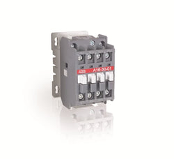
A16-30-10 230-240V 50Hz / 240-260V 60Hz Contactor

A16-40-00 42V 50Hz / 42V 60Hz Contactor
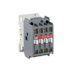
A16-30-10 24V 50Hz / 24V 60Hz Contactor
A16-30-01 400-415V 50Hz / 415-440V 60Hz Contactor
Ordering
1 piece
85362010
Popular Downloads
Dimensions
45 mm
90 mm
86.75 mm
0.265 kg
Technical
(230 V AC) 100 kA
(250 V DC) 3 Poles in Series 10 kA
(400 V AC) 100 kA
(440 V AC) 30 kA
(500 V AC) 20 kA
(690 V AC) 3 kA
(230 V AC) 100 kA
(250 V DC) 3 Poles in Series 10 kA
(400 V AC) 100 kA
(440 V AC) 30 kA
(500 V AC) 20 kA
(690 V AC) 3 kA
(230 V AC) 100 kA
(400 V AC) 100 kA
(440 V AC) 30 kA
(500 V AC) 20 kA
(690 V AC) 3 kA
(230 V AC) 100 kA
(400 V AC) 100 kA
(440 V AC) 30 kA
(500 V AC) 20 kA
(690 V AC) 3 kA
150 A
6.3 ... 10 A
(400 V) Three Phase 4 kW
(400 V) Three Phase 4 kW
Main Circuit 690 V AC
Main Circuit 250 V DC
Main Circuit 690 V AC
Main Circuit 250 V DC
10 A
10 A
10 A
10 A
Main Circuit 50 Hz
Main Circuit 60 Hz
Main Circuit 50 Hz
Main Circuit 60 Hz
0 ... 400 Hz
Main Circuit 6 kV
690 V
at Rated Operating Conditions per Pole 0.8 ... 2.0 W
3P
Main Circuit 10 A
Housing IP20
Main Circuit Terminals IP10
Housing IP20
Main Circuit Terminals IP10
3
50000 cycle
Nr. Operations 100000 cycle
Screw Terminals
Flexible with Ferrule 1/2x 0.75 ... 2.5 mm²
Flexible with Insulated Ferrule 1/2x 0.75 ... 2.5 mm²
Flexible 1/2x 0.75 ... 2.5 mm²
Rigid 1/2x 1 ... 4 mm²
Flexible with Ferrule 1/2x 0.75 ... 2.5 mm²
Flexible with Insulated Ferrule 1/2x 0.75 ... 2.5 mm²
Flexible 1/2x 0.75 ... 2.5 mm²
Rigid 1/2x 1 ... 4 mm²
Main Circuit 0.8 ... 1.2 N·m
Auxiliary Circuit 8 mm
Main Circuit 9 mm
Auxiliary Circuit 8 mm
Main Circuit 9 mm
Pozidriv 2
1 ... 6
TH35-15 (35 x 15 mm Mounting Rail) acc. to IEC 60715
TH35-7.5 (35 x 7.5 mm Mounting Rail) acc. to IEC 60715
TH35-15 (35 x 15 mm Mounting Rail) acc. to IEC 60715
TH35-7.5 (35 x 7.5 mm Mounting Rail) acc. to IEC 60715
Electrical Conductive Board, Horizontal - Up to 400 V 0 mm
Electrical Conductive Board, Horizontal - Up to 690 V 1.5 mm
Electrical Conductive Board, Vertical 75 mm
Other Device Same Type, Horizontal 0 mm
Other Device Same Type, Vertical 150 mm
Electrical Conductive Board, Horizontal - Up to 400 V 0 mm
Electrical Conductive Board, Horizontal - Up to 690 V 1.5 mm
Electrical Conductive Board, Vertical 75 mm
Other Device Same Type, Horizontal 0 mm
Other Device Same Type, Vertical 150 mm
Rotary Handle
ON / OFF / TRIP
IEC/EN 60947-1
IEC/EN 60947-2
IEC/EN 60947-4-1
UL 60947-1
UL 60947-4-1
IEC 60335-2-40 A2L
IEC/EN 60947-1
IEC/EN 60947-2
IEC/EN 60947-4-1
UL 60947-1
UL 60947-4-1
IEC 60335-2-40 A2L
UL508 Self-Protected Combination Motor Controller (Type E) in combination with feeder block S1-M3-xx
Technical UL/CSA
Manual Self-Protected Combination Controllers (Type E), (480Y / 277 V AC) 65 kA
Manual Self-Protected Combination Controllers (Type E), (600Y / 347 V AC) 18 kA
Any UL Listed Fuses or Circuit-Breakers, Group Installations (480 V AC) 65 kA
Any UL Listed Fuses or Circuit-Breakers, Group Installations (600 V AC) 35 kA
Any UL Listed Fuses or Circuit-Breakers, Motor Disconnect (480 V AC) 65 kA
Any UL Listed Fuses or Circuit-Breakers, Motor Disconnect (600 V AC) 18 kA
Any UL Listed Fuses or Circuit-Breakers, Tap Conductor Protection in Group Installations (480Y / 277 V AC) 65 kA
Any UL Listed Fuses or Circuit-Breakers, Tap Conductor Protection in Group Installations (600Y / 347 V AC) 18 kA
Main Circuit 600 V AC
(200 V AC) Three Phase 2 Hp
(208 V AC) Three Phase 2 Hp
(220 ... 240 V AC) Three Phase 3 Hp
(440 ... 480 V AC) Three Phase 5 Hp
(550 ... 600 V AC) Three Phase 7.5 Hp
(200 V AC) Three Phase 2 Hp
(208 V AC) Three Phase 2 Hp
(220 ... 240 V AC) Three Phase 3 Hp
(440 ... 480 V AC) Three Phase 5 Hp
(550 ... 600 V AC) Three Phase 7.5 Hp
(200 V AC) Three Phase 7.8 A
(208 V AC) Three Phase 7.5 A
(220 ... 240 V AC) Three Phase 9.6 A
(440 ... 480 V AC) Three Phase 7.6 A
(550 ... 600 V AC) Three Phase 9 A
(200 V AC) Three Phase 7.8 A
(208 V AC) Three Phase 7.5 A
(220 ... 240 V AC) Three Phase 9.6 A
(440 ... 480 V AC) Three Phase 7.6 A
(550 ... 600 V AC) Three Phase 9 A
(200 V AC) Three Phase 57.5 A
(208 V AC) Three Phase 55 A
(220 ... 240 V AC) Three Phase 64 A
(440 ... 480 V AC) Three Phase 46 A
(550 ... 600 V AC) Three Phase 50.8 A
(200 V AC) Three Phase 57.5 A
(208 V AC) Three Phase 55 A
(220 ... 240 V AC) Three Phase 64 A
(440 ... 480 V AC) Three Phase 46 A
(550 ... 600 V AC) Three Phase 50.8 A
(600 V AC) 10 A
Flexible 1/2x 16-12 AWG
Stranded 1/2x 16-12 AWG
Flexible 1/2x 16-12 AWG
Stranded 1/2x 16-12 AWG
Main Circuit 10 ... 12 in·lb
Environmental
Around the Enclosure 0 ... +40 °C
Operation -25 ... +70 °C
Operation Compensated -25 ... +60 °C
Storage -50 ... +80 °C
Around the Enclosure 0 ... +40 °C
Operation -25 ... +70 °C
Operation Compensated -25 ... +60 °C
Storage -50 ... +80 °C
Yes
2000 m
11 ms Pulse 25g
5g 3 ... 150 Hz
Material Compliance
Following EU Directive 2011/65/EU and Amendment 2015/863 July 22, 2019
Business To Business
5. Small Equipment (No External Dimension More Than 50 cm)
ABB EcoSolutions
Certificates and Declarations
Container Information
box 1 piece
92 mm
95 mm
50 mm
0.28 kg
4013614400100
carton 40 piece
280 mm
395 mm
210 mm
11.586 kg
4013614409004
External Classifications and Standards
F
EC000074 - Motor protection circuit-breaker
EC000074 - Motor protection circuit-breaker
V11.0 : 27370401
39121521
4731 >> Manual Starters
3705994
4364079
3112126

AL16-30-10 240V DC Contactor
MS165-16 Motor circuit breaker 10-16A MS16516
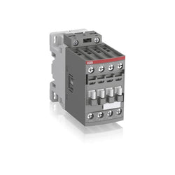
Ordering
1 piece
85364900
Popular Downloads
Dimensions
45 mm
101 mm
86 mm
0.4 kg
Technical
4
0
0
0
4P
IEC/EN 60947-1, IEC/EN 60947-4-1, UL 60335-2-40 LZGH2 A2L, UL 60947-1, UL 60947-4-1, CSA C22.2 No. 60335-2-40 LZGH2 A2L, CAN/CSA C22.2 No.60947-1, CAN/CSA C22.2 No.60947-4-1
Main Circuit 690 V
Main Circuit 50 / 60 Hz
acc. to IEC 60947-4-1, Open Contactors Θ = 40 °C 55 A
(690 V) 40 °C 45 A
(690 V) 60 °C 40 A
(690 V) 70 °C 32 A
(690 V) 40 °C 45 A
(690 V) 60 °C 40 A
(690 V) 70 °C 32 A
(415 V) 60 °C 21.2 A
(440 V) 60 °C 20 A
(500 V) 60 °C 17.6 A
(690 V) 60 °C 10.5 A
(380 / 400 V) 60 °C 22 A
(220 / 230 / 240 V) 60 °C 23.2 A
(415 V) 60 °C 21.2 A
(440 V) 60 °C 20 A
(500 V) 60 °C 17.6 A
(690 V) 60 °C 10.5 A
(380 / 400 V) 60 °C 22 A
(220 / 230 / 240 V) 60 °C 23.2 A
(110 V) 2 Poles in Series, 40 °C 45 A
(110 V) 2 Poles in Series, 60 °C 40 A
(110 V) 2 Poles in Series, 70 °C 32 A
(110 V) 3 Poles in Series, 40 °C 45 A
(110 V) 3 Poles in Series, 60 °C 40 A
(110 V) 3 Poles in Series, 70 °C 32 A
(110 V) 4 Poles in Series, 40 °C 45 A
(110 V) 4 Poles in Series, 60 °C 40 A
(110 V) 4 Poles in Series, 70 °C 32 A
(220 V) 3 Poles in Series, 40 °C 45 A
(220 V) 3 Poles in Series, 60 °C 40 A
(220 V) 3 Poles in Series, 70 °C 32 A
(220 V) 4 Poles in Series, 40 °C 45 A
(220 V) 4 Poles in Series, 60 °C 40 A
(220 V) 4 Poles in Series, 70 °C 32 A
(72 V) 1-Pole, 40 °C 45 A
(72 V) 1-Pole, 60 °C 40 A
(72 V) 1-Pole, 70 °C 32 A
(72 V) 2 Poles in Series, 40 °C 45 A
(72 V) 2 Poles in Series, 60 °C 40 A
(72 V) 2 Poles in Series, 70 °C 32 A
(72 V) 3 Poles in Series, 40 °C 45 A
(72 V) 3 Poles in Series, 60 °C 40 A
(72 V) 3 Poles in Series, 70 °C 32 A
(72 V) 4 Poles in Series, 40 °C 45 A
(72 V) 4 Poles in Series, 60 °C 40 A
(72 V) 4 Poles in Series, 70 °C 32 A
(110 V) 2 Poles in Series, 40 °C 45 A
(110 V) 2 Poles in Series, 60 °C 40 A
(110 V) 2 Poles in Series, 70 °C 32 A
(110 V) 3 Poles in Series, 40 °C 45 A
(110 V) 3 Poles in Series, 60 °C 40 A
(110 V) 3 Poles in Series, 70 °C 32 A
(110 V) 4 Poles in Series, 40 °C 45 A
(110 V) 4 Poles in Series, 60 °C 40 A
(110 V) 4 Poles in Series, 70 °C 32 A
(220 V) 3 Poles in Series, 40 °C 45 A
(400 V) 11 kW
(415 V) 11 kW
(440 V) 11 kW
(500 V) 11 kW
(690 V) 9 kW
(220 / 230 / 240 V) 5.5 kW
(400 V) 11 kW
(415 V) 11 kW
(440 V) 11 kW
(500 V) 11 kW
(690 V) 9 kW
(220 / 230 / 240 V) 5.5 kW
at 40 °C Ambient Temp, in Free Air, from a Cold State 10 s 300 A
at 40 °C Ambient Temp, in Free Air, from a Cold State 15 min 55 A
at 40 °C Ambient Temp, in Free Air, from a Cold State 1 min 150 A
at 40 °C Ambient Temp, in Free Air, from a Cold State 1 s 450 A
at 40 °C Ambient Temp, in Free Air, from a Cold State 30 s 225 A
acc. to IEC 60947-4-1 690 V
acc. to UL/CSA 600 V
acc. to IEC 60947-4-1 690 V
acc. to UL/CSA 600 V
6 kV
(AC-1) 600 cycles per hour
3600 cycles per hour
DC Operation 12 ... 20 V
at Rated Operating Conditions AC-1 per Pole 1.6 W
at Rated Operating Conditions AC-3 per Pole 0.42 W
at Rated Operating Conditions AC-1 per Pole 1.6 W
at Rated Operating Conditions AC-3 per Pole 0.42 W
Between Coil De-energization and NC Contact Closing 13 ... 98 ms
Between Coil De-energization and NO Contact Opening 11 ... 95 ms
Between Coil Energization and NC Contact Opening 38 ... 90 ms
Between Coil Energization and NO Contact Closing 40 ... 95 ms
Between Coil De-energization and NC Contact Closing 13 ... 98 ms
Between Coil De-energization and NO Contact Opening 11 ... 95 ms
Between Coil Energization and NC Contact Opening 38 ... 90 ms
Between Coil Energization and NO Contact Closing 40 ... 95 ms
TH35-15 (35 x 15 mm Mounting Rail) acc. to IEC 60715
TH35-7.5 (35 x 7.5 mm Mounting Rail) acc. to IEC 60715
TH35-15 (35 x 15 mm Mounting Rail) acc. to IEC 60715
TH35-7.5 (35 x 7.5 mm Mounting Rail) acc. to IEC 60715
2 x M4 Screws Placed Diagonally
Flexible with Ferrule 1/2x 1.5 ... 16 mm²
Flexible with Insulated Ferrule 1/2x 1.5 ... 16 mm²
Rigid Solid 1/2x 1.5 ... 4 mm²
Rigid Stranded 1/2x 1.5 ... 16 mm²
Flexible with Ferrule 1/2x 1.5 ... 16 mm²
Flexible with Insulated Ferrule 1/2x 1.5 ... 16 mm²
Rigid Solid 1/2x 1.5 ... 4 mm²
Rigid Stranded 1/2x 1.5 ... 16 mm²
Flexible with Ferrule 1/2x 0.75 ... 2.5 mm²
Flexible with Insulated Ferrule 1x 0.75 ... 2.5 mm²
Flexible with Insulated Ferrule 2x 0.75 ... 1.5 mm²
Rigid Solid 1/2x 1 ... 2.5 mm²
Rigid Stranded 1/2x 1 ... 2.5 mm²
Flexible with Ferrule 1/2x 0.75 ... 2.5 mm²
Flexible with Insulated Ferrule 1x 0.75 ... 2.5 mm²
Flexible with Insulated Ferrule 2x 0.75 ... 1.5 mm²
Rigid Solid 1/2x 1 ... 2.5 mm²
Rigid Stranded 1/2x 1 ... 2.5 mm²
Control Circuit 10 mm
Main Circuit 12 mm
Control Circuit 10 mm
Main Circuit 12 mm
acc. to IEC 60529, IEC 60947-1, EN 60529 Coil Terminals IP20
acc. to IEC 60529, IEC 60947-1, EN 60529 Main Terminals IP20
acc. to IEC 60529, IEC 60947-1, EN 60529 Coil Terminals IP20
acc. to IEC 60529, IEC 60947-1, EN 60529 Main Terminals IP20
Control Circuit 1.2 N·m
Main Circuit 2.5 N·m
Control Circuit 1.2 N·m
Main Circuit 2.5 N·m
Screw Terminals
Block Contactor
Technical UL/CSA
Main Circuit 600 V
(600 V AC) 45 A
Rigid Solid 1/2x 16-10 AWG
Rigid Stranded 1/2x 16-6 AWG
Rigid Solid 1/2x 16-10 AWG
Rigid Stranded 1/2x 16-6 AWG
Rigid Solid 1/2x 18-14 AWG
Rigid Stranded 1/2x 18-14 AWG
Rigid Solid 1/2x 18-14 AWG
Rigid Stranded 1/2x 18-14 AWG
Control Circuit 11 in·lb
Main Circuit 22 in·lb
Control Circuit 11 in·lb
Main Circuit 22 in·lb
Environmental
Close to Contactor for Storage -60 ... +80 °C
Near Contactor for Operation in Free Air -40 ... 70 °C
Close to Contactor for Storage -60 ... +80 °C
Near Contactor for Operation in Free Air -40 ... 70 °C
Category B according to IEC 60947-1 Annex Q
Without Derating 3000 m
Closed, Shock Direction: B1 25 g
Open, Shock Direction: B1 5 g
Shock Direction: A 30 g
Shock Direction: B2 15 g
Shock Direction: C1 25 g
Shock Direction: C2 25 g
Closed, Shock Direction: B1 25 g
Open, Shock Direction: B1 5 g
Shock Direction: A 30 g
Shock Direction: B2 15 g
Shock Direction: C1 25 g
Shock Direction: C2 25 g
4g Closed Position & 2g Open position 5 ... 300 Hz
3
Material Compliance
Following EU Directive 2011/65/EU and Amendment 2015/863 July 22, 2019
Business To Business
5. Small Equipment (No External Dimension More Than 50 cm)
ABB EcoSolutions
Recycled Cardboard - 86 %
Recycled Metal - 28 %
Certificates and Declarations
Container Information
box 1 piece
87 mm
103 mm
47 mm
0.4 kg
3471523116009
box 18 piece
250 mm
300 mm
315 mm
14.4 kg
External Classifications and Standards
Q
EC000066 - Power contactor, AC switching
EC000066 - Power contactor, AC switching
EC000066 - Power contactor, AC switching
V11.0 : 27371003
39121529
4758 >> Iec Contactors
3705832
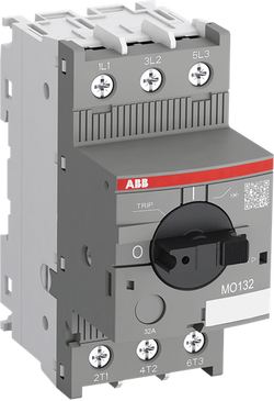
Ordering
1 piece
85362010
Popular Downloads
Dimensions
45 mm
97.8 mm
86.55 mm
0.31 kg
Technical
(230 V AC) 100 kA
(400 V AC) 100 kA
(440 V AC) 20 kA
(500 V AC) 20 kA
(690 V AC) 3 kA
(230 V AC) 100 kA
(400 V AC) 100 kA
(440 V AC) 20 kA
(500 V AC) 20 kA
(690 V AC) 3 kA
(230 V AC) 100 kA
(400 V AC) 100 kA
(440 V AC) 20 kA
(500 V AC) 20 kA
(690 V AC) 3 kA
(230 V AC) 100 kA
(400 V AC) 100 kA
(440 V AC) 20 kA
(500 V AC) 20 kA
(690 V AC) 3 kA
200 A
None
(400 V) Three Phase 7.5 kW
(400 V) Three Phase 7.5 kW
Main Circuit 690 V AC
16 A
16 A
16 A
Main Circuit 50 Hz
Main Circuit 60 Hz
Main Circuit 50 Hz
Main Circuit 60 Hz
0 ... 400 Hz
Main Circuit 6 kV
690 V
at Rated Operating Conditions per Pole 1.9 W
3P
Main Circuit 16 A
Housing IP20
Main Circuit Terminals IP10
Housing IP20
Main Circuit Terminals IP10
3
50000 cycle
Nr. Operations 100000 cycle
Screw Terminals
Flexible with Ferrule 1/2x 0.75 ... 6 mm²
Flexible with Insulated Ferrule 1/2x 0.75 ... 6 mm²
Flexible 1/2x 1 ... 2.5 mm²
Flexible 1/2x 2.5 ... 6 mm²
Rigid 1/2x 1 ... 2.5 mm²
Rigid 1/2x 2.5 ... 6 mm²
Flexible with Ferrule 1/2x 0.75 ... 6 mm²
Flexible with Insulated Ferrule 1/2x 0.75 ... 6 mm²
Flexible 1/2x 1 ... 2.5 mm²
Flexible 1/2x 2.5 ... 6 mm²
Rigid 1/2x 1 ... 2.5 mm²
Rigid 1/2x 2.5 ... 6 mm²
Main Circuit 1.5 N·m
Main Circuit 10 mm
Pozidriv 2
1 ... 6
TH35-15 (35 x 15 mm Mounting Rail) acc. to IEC 60715
TH35-7.5 (35 x 7.5 mm Mounting Rail) acc. to IEC 60715
TH35-15 (35 x 15 mm Mounting Rail) acc. to IEC 60715
TH35-7.5 (35 x 7.5 mm Mounting Rail) acc. to IEC 60715
Electrical Conductive Board, Horizontal - Up to 400 V 0 mm
Electrical Conductive Board, Horizontal - Up to 690 V 1.5 mm
Electrical Conductive Board, Vertical 75 mm
Other Device Same Type, Horizontal 0 mm
Other Device Same Type, Vertical 150 mm
Electrical Conductive Board, Horizontal - Up to 400 V 0 mm
Electrical Conductive Board, Horizontal - Up to 690 V 1.5 mm
Electrical Conductive Board, Vertical 75 mm
Other Device Same Type, Horizontal 0 mm
Other Device Same Type, Vertical 150 mm
Rotary Handle
ON / OFF / TRIP
IEC/EN 60947-1
IEC/EN 60947-2
IEC/EN 60947-4-1
UL 60947-1
UL 60947-4-1
IEC 60335-2-40 A2L
IEC/EN 60947-1
IEC/EN 60947-2
IEC/EN 60947-4-1
UL 60947-1
UL 60947-4-1
IEC 60335-2-40 A2L
For overload protection of the motors, an appropriate thermal or electronic overload relays must be used
Technical UL/CSA
Any UL Listed Fuses or Circuit-Breakers, Group Installations (480 V AC) 35 kA
Any UL Listed Fuses or Circuit-Breakers, Group Installations (600 V AC) 35 kA
Any UL Listed Fuses or Circuit-Breakers, Motor Disconnect (480 V AC) 30 kA
Any UL Listed Fuses or Circuit-Breakers, Motor Disconnect (600 V AC) 18 kA
Any UL Listed Fuses or Circuit-Breakers, Tap Conductor Protection in Group Installations (480Y / 277 V AC) 30 kA
Any UL Listed Fuses or Circuit-Breakers, Tap Conductor Protection in Group Installations (600Y / 347 V AC) 18 kA
Main Circuit 600 V AC
(200 V AC) Three Phase 3 Hp
(208 V AC) Three Phase 3 Hp
(220 ... 240 V AC) Three Phase 5 Hp
(440 ... 480 V AC) Three Phase 10 Hp
(550 ... 600 V AC) Three Phase 10 Hp
(200 V AC) Three Phase 3 Hp
(208 V AC) Three Phase 3 Hp
(220 ... 240 V AC) Three Phase 5 Hp
(440 ... 480 V AC) Three Phase 10 Hp
(550 ... 600 V AC) Three Phase 10 Hp
(200 V AC) Three Phase 11 A
(208 V AC) Three Phase 10.6 A
(220 ... 240 V AC) Three Phase 15.2 A
(440 ... 480 V AC) Three Phase 14 A
(550 ... 600 V AC) Three Phase 11 A
(200 V AC) Three Phase 11 A
(208 V AC) Three Phase 10.6 A
(220 ... 240 V AC) Three Phase 15.2 A
(440 ... 480 V AC) Three Phase 14 A
(550 ... 600 V AC) Three Phase 11 A
(200 V AC) Three Phase 73.6 A
(208 V AC) Three Phase 71 A
(220 ... 240 V AC) Three Phase 92 A
(440 ... 480 V AC) Three Phase 81 A
(550 ... 600 V AC) Three Phase 64.8 A
(200 V AC) Three Phase 73.6 A
(208 V AC) Three Phase 71 A
(220 ... 240 V AC) Three Phase 92 A
(440 ... 480 V AC) Three Phase 81 A
(550 ... 600 V AC) Three Phase 64.8 A
(600 V AC) 16 A
Flexible 1/2x 16-8 AWG
Stranded 1/2x 16-8 AWG
Flexible 1/2x 16-8 AWG
Stranded 1/2x 16-8 AWG
Main Circuit 18 in·lb
Environmental
Around the Enclosure 0 ... +40 °C
Operation -25 ... +60 °C
Storage -50 ... +80 °C
Around the Enclosure 0 ... +40 °C
Operation -25 ... +60 °C
Storage -50 ... +80 °C
No
2000 m
11 ms Pulse 25g
5g 3 ... 150 Hz
Material Compliance
Following EU Directive 2011/65/EU and Amendment 2015/863 July 22, 2019
Business To Business
5. Small Equipment (No External Dimension More Than 50 cm)
ABB EcoSolutions
Certificates and Declarations
Container Information
box 1 piece
92 mm
102 mm
50 mm
0.325 kg
4013614400261
carton 40 piece
280 mm
395 mm
210 mm
13.386 kg
4013614443718
External Classifications and Standards
F
EC000074 - Motor protection circuit-breaker
EC000074 - Motor protection circuit-breaker
V11.0 : 27370401
39121521
4731 >> Manual Starters
3705890
4364096
3110039
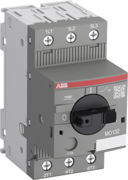
Ordering
1 piece
85362010
Popular Downloads
Dimensions
45 mm
90 mm
86.75 mm
0.265 kg
Technical
(230 V AC) 100 kA
(400 V AC) 100 kA
(440 V AC) 30 kA
(500 V AC) 20 kA
(690 V AC) 3 kA
(230 V AC) 100 kA
(400 V AC) 100 kA
(440 V AC) 30 kA
(500 V AC) 20 kA
(690 V AC) 3 kA
(230 V AC) 100 kA
(400 V AC) 100 kA
(440 V AC) 30 kA
(500 V AC) 20 kA
(690 V AC) 3 kA
(230 V AC) 100 kA
(400 V AC) 100 kA
(440 V AC) 30 kA
(500 V AC) 20 kA
(690 V AC) 3 kA
78.8 A
None
(400 V) Three Phase 2.2 kW
(400 V) Three Phase 2.2 kW
Main Circuit 690 V AC
6.3 A
6.3 A
6.3 A
Main Circuit 50 Hz
Main Circuit 60 Hz
Main Circuit 50 Hz
Main Circuit 60 Hz
0 ... 400 Hz
Main Circuit 6 kV
690 V
at Rated Operating Conditions per Pole 1.1 W
3P
Main Circuit 6.3 A
Housing IP20
Main Circuit Terminals IP10
Housing IP20
Main Circuit Terminals IP10
3
50000 cycle
Nr. Operations 100000 cycle
Screw Terminals
Flexible with Ferrule 1/2x 0.75 ... 2.5 mm²
Flexible with Insulated Ferrule 1/2x 0.75 ... 2.5 mm²
Flexible 1/2x 0.75 ... 2.5 mm²
Rigid 1/2x 1 ... 4 mm²
Flexible with Ferrule 1/2x 0.75 ... 2.5 mm²
Flexible with Insulated Ferrule 1/2x 0.75 ... 2.5 mm²
Flexible 1/2x 0.75 ... 2.5 mm²
Rigid 1/2x 1 ... 4 mm²
Main Circuit 0.8 ... 1.2 N·m
Main Circuit 9 mm
Pozidriv 2
1 ... 6
TH35-15 (35 x 15 mm Mounting Rail) acc. to IEC 60715
TH35-7.5 (35 x 7.5 mm Mounting Rail) acc. to IEC 60715
TH35-15 (35 x 15 mm Mounting Rail) acc. to IEC 60715
TH35-7.5 (35 x 7.5 mm Mounting Rail) acc. to IEC 60715
Electrical Conductive Board, Horizontal - Up to 400 V 0 mm
Electrical Conductive Board, Horizontal - Up to 690 V 1.5 mm
Electrical Conductive Board, Vertical 75 mm
Other Device Same Type, Horizontal 0 mm
Other Device Same Type, Vertical 150 mm
Electrical Conductive Board, Horizontal - Up to 400 V 0 mm
Electrical Conductive Board, Horizontal - Up to 690 V 1.5 mm
Electrical Conductive Board, Vertical 75 mm
Other Device Same Type, Horizontal 0 mm
Other Device Same Type, Vertical 150 mm
Rotary Handle
ON / OFF / TRIP
IEC/EN 60947-1
IEC/EN 60947-2
IEC/EN 60947-4-1
UL 60947-1
UL 60947-4-1
IEC 60335-2-40 A2L
IEC/EN 60947-1
IEC/EN 60947-2
IEC/EN 60947-4-1
UL 60947-1
UL 60947-4-1
IEC 60335-2-40 A2L
For overload protection of the motors, an appropriate thermal or electronic overload relays must be used
Technical UL/CSA
Any UL Listed Fuses or Circuit-Breakers, Group Installations (480 V AC) 65 kA
Any UL Listed Fuses or Circuit-Breakers, Group Installations (600 V AC) 35 kA
Any UL Listed Fuses or Circuit-Breakers, Motor Disconnect (480 V AC) 65 kA
Any UL Listed Fuses or Circuit-Breakers, Motor Disconnect (600 V AC) 18 kA
Any UL Listed Fuses or Circuit-Breakers, Tap Conductor Protection in Group Installations (480Y / 277 V AC) 65 kA
Any UL Listed Fuses or Circuit-Breakers, Tap Conductor Protection in Group Installations (600Y / 347 V AC) 18 kA
Main Circuit 600 V AC
(200 V AC) Three Phase 1 Hp
(208 V AC) Three Phase 1 Hp
(220 ... 240 V AC) Three Phase 1.5 Hp
(440 ... 480 V AC) Three Phase 3 Hp
(550 ... 600 V AC) Three Phase 5 Hp
(200 V AC) Three Phase 1 Hp
(208 V AC) Three Phase 1 Hp
(220 ... 240 V AC) Three Phase 1.5 Hp
(440 ... 480 V AC) Three Phase 3 Hp
(550 ... 600 V AC) Three Phase 5 Hp
(200 V AC) Three Phase 6.3 A
(208 V AC) Three Phase 6.3 A
(220 ... 240 V AC) Three Phase 6.3 A
(440 ... 480 V AC) Three Phase 4.8 A
(550 ... 600 V AC) Three Phase 6.1 A
(200 V AC) Three Phase 6.3 A
(208 V AC) Three Phase 6.3 A
(220 ... 240 V AC) Three Phase 6.3 A
(440 ... 480 V AC) Three Phase 4.8 A
(550 ... 600 V AC) Three Phase 6.1 A
(200 V AC) Three Phase 37.8 A
(208 V AC) Three Phase 37.8 A
(220 ... 240 V AC) Three Phase 37.8 A
(440 ... 480 V AC) Three Phase 32 A
(550 ... 600 V AC) Three Phase 36.8 A
(200 V AC) Three Phase 37.8 A
(208 V AC) Three Phase 37.8 A
(220 ... 240 V AC) Three Phase 37.8 A
(440 ... 480 V AC) Three Phase 32 A
(550 ... 600 V AC) Three Phase 36.8 A
(600 V AC) 6.3 A
Flexible 1/2x 16-12 AWG
Stranded 1/2x 16-12 AWG
Flexible 1/2x 16-12 AWG
Stranded 1/2x 16-12 AWG
Main Circuit 10 in·lb
Environmental
Around the Enclosure 0 ... +40 °C
Operation -25 ... +60 °C
Storage -50 ... +80 °C
Around the Enclosure 0 ... +40 °C
Operation -25 ... +60 °C
Storage -50 ... +80 °C
No
2000 m
11 ms Pulse 25g
5g 3 ... 150 Hz
Material Compliance
Following EU Directive 2011/65/EU and Amendment 2015/863 July 22, 2019
Business To Business
5. Small Equipment (No External Dimension More Than 50 cm)
ABB EcoSolutions
Certificates and Declarations
Container Information
box 1 piece
92 mm
95 mm
50 mm
0.28 kg
4013614400247
carton 40 piece
280 mm
395 mm
210 mm
11.586 kg
4013614443695
External Classifications and Standards
F
EC000074 - Motor protection circuit-breaker
EC000074 - Motor protection circuit-breaker
V11.0 : 27370401
39121521
4731 >> Manual Starters
3705887
4364093
3110037

MS132 25-32A Motor protection switch 25 kA EP 888 0

Ordering
1 piece
85364900
Popular Downloads
Dimensions
45 mm
86 mm
86 mm
0.35 kg
Technical
3
0
0
0
3P
IEC/EN 60947-1, IEC/EN 60947-4-1, UL 60335-2-40 LZGH2 A2L, UL 60947-4-1, CSA C22.2 No. 60335-2-40 LZGH2 A2L, CSA C22.2 No. 60947-4-1
Main Circuit 690 V
Control Circuit 50 / 60 Hz
Main Circuit 50 / 60 Hz
Control Circuit 50 / 60 Hz
Main Circuit 50 / 60 Hz
acc. to IEC 60947-4-1, Open Contactors Θ = 40 °C 50 A
(690 V) 40 °C 45 A
(690 V) 60 °C 40 A
(690 V) 70 °C 32 A
(690 V) 40 °C 45 A
(690 V) 60 °C 40 A
(690 V) 70 °C 32 A
(415 V) 60 °C 26 A
(440 V) 60 °C 26 A
(500 V) 60 °C 23 A
(690 V) 60 °C 17 A
(380 / 400 V) 60 °C 26 A
(220 / 230 / 240 V) 60 °C 26 A
(415 V) 60 °C 26 A
(440 V) 60 °C 26 A
(500 V) 60 °C 23 A
(690 V) 60 °C 17 A
(380 / 400 V) 60 °C 26 A
(220 / 230 / 240 V) 60 °C 26 A
(415 V) 60 °C 26 A
(440 V) 60 °C 26 A
(500 V) 60 °C 23 A
(690 V) 60 °C 17 A
(380 / 400 V) 60 °C 26 A
(220 / 230 / 240 V) 60 °C 26 A
(415 V) 60 °C 26 A
(440 V) 60 °C 26 A
(500 V) 60 °C 23 A
(690 V) 60 °C 17 A
(380 / 400 V) 60 °C 26 A
(220 / 230 / 240 V) 60 °C 26 A
(110 V) 2 Poles in Series, 40 °C 45 A
(110 V) 2 Poles in Series, 60 °C 40 A
(110 V) 2 Poles in Series, 70 °C 32 A
(110 V) 3 Poles in Series, 40 °C 45 A
(110 V) 3 Poles in Series, 60 °C 40 A
(110 V) 3 Poles in Series, 70 °C 32 A
(220 V) 3 Poles in Series, 40 °C 45 A
(220 V) 3 Poles in Series, 60 °C 40 A
(220 V) 3 Poles in Series, 70 °C 32 A
(72 V) 1-Pole, 40 °C 45 A
(72 V) 1-Pole, 60 °C 40 A
(72 V) 1-Pole, 70 °C 32 A
(72 V) 2 Poles in Series, 40 °C 45 A
(72 V) 2 Poles in Series, 60 °C 40 A
(72 V) 2 Poles in Series, 70 °C 32 A
(72 V) 3 Poles in Series, 40 °C 45 A
(72 V) 3 Poles in Series, 60 °C 40 A
(72 V) 3 Poles in Series, 70 °C 32 A
(110 V) 2 Poles in Series, 40 °C 45 A
(110 V) 2 Poles in Series, 60 °C 40 A
(110 V) 2 Poles in Series, 70 °C 32 A
(110 V) 3 Poles in Series, 40 °C 45 A
(110 V) 3 Poles in Series, 60 °C 40 A
(110 V) 3 Poles in Series, 70 °C 32 A
(220 V) 3 Poles in Series, 40 °C 45 A
(220 V) 3 Poles in Series, 60 °C 40 A
(220 V) 3 Poles in Series, 70 °C 32 A
(72 V) 1-Pole, 40 °C 45 A
(72 V) 1-Pole, 60 °C 40 A
(72 V) 1-Pole, 70 °C 32 A
(72 V) 2 Poles in Series, 40 °C 45 A
(72 V) 2 Poles in Series, 60 °C 40 A
(72 V) 2 Poles in Series, 70 °C 32 A
(72 V) 3 Poles in Series, 40 °C 45 A
(72 V) 3 Poles in Series, 60 °C 40 A
(72 V) 3 Poles in Series, 70 °C 32 A
(110 V) 2 Poles in Series, 40 °C 45 A
(110 V) 2 Poles in Series, 60 °C 40 A
(110 V) 2 Poles in Series, 70 °C 32 A
(110 V) 3 Poles in Series, 40 °C 45 A
(110 V) 3 Poles in Series, 60 °C 40 A
(110 V) 3 Poles in Series, 70 °C 32 A
(220 V) 3 Poles in Series, 40 °C 45 A
(220 V) 3 Poles in Series, 60 °C 40 A
(220 V) 3 Poles in Series, 70 °C 32 A
(72 V) 1-Pole, 40 °C 45 A
(110 V) 2 Poles in Series, 40 °C 45 A
(110 V) 2 Poles in Series, 60 °C 40 A
(110 V) 2 Poles in Series, 70 °C 32 A
(110 V) 3 Poles in Series, 40 °C 45 A
(110 V) 3 Poles in Series, 60 °C 40 A
(110 V) 3 Poles in Series, 70 °C 32 A
(220 V) 3 Poles in Series, 40 °C 20 A
(220 V) 3 Poles in Series, 60 °C 20 A
(220 V) 3 Poles in Series, 70 °C 20 A
(72 V) 1-Pole, 40 °C 20 A
(72 V) 1-Pole, 60 °C 20 A
(72 V) 1-Pole, 70 °C 20 A
(72 V) 2 Poles in Series, 40 °C 45 A
(72 V) 2 Poles in Series, 60 °C 40 A
(72 V) 2 Poles in Series, 70 °C 32 A
(72 V) 3 Poles in Series, 40 °C 45 A
(72 V) 3 Poles in Series, 60 °C 40 A
(72 V) 3 Poles in Series, 70 °C 32 A
(110 V) 2 Poles in Series, 40 °C 45 A
(110 V) 2 Poles in Series, 60 °C 40 A
(110 V) 2 Poles in Series, 70 °C 32 A
(110 V) 3 Poles in Series, 40 °C 45 A
(110 V) 3 Poles in Series, 60 °C 40 A
(110 V) 3 Poles in Series, 70 °C 32 A
(220 V) 3 Poles in Series, 40 °C 20 A
(220 V) 3 Poles in Series, 60 °C 20 A
(220 V) 3 Poles in Series, 70 °C 20 A
(72 V) 1-Pole, 40 °C 20 A
(400 V) 11 kW
(415 V) 11 kW
(440 V) 15 kW
(500 V) 15 kW
(690 V) 15 kW
(380 / 400 V) 11 kW
(220 / 230 / 240 V) 6.5 kW
(400 V) 11 kW
(415 V) 11 kW
(440 V) 15 kW
(500 V) 15 kW
(690 V) 15 kW
(380 / 400 V) 11 kW
(220 / 230 / 240 V) 6.5 kW
(415 V) 11 kW
(440 V) 15 kW
(500 V) 15 kW
(690 V) 15 kW
(380 / 400 V) 11 kW
(220 / 230 / 240 V) 6.5 kW
(415 V) 11 kW
(440 V) 15 kW
(500 V) 15 kW
(690 V) 15 kW
(380 / 400 V) 11 kW
(220 / 230 / 240 V) 6.5 kW
at 40 °C Ambient Temp, in Free Air, from a Cold State 10 s 350 A
at 40 °C Ambient Temp, in Free Air, from a Cold State 15 min 50 A
at 40 °C Ambient Temp, in Free Air, from a Cold State 1 min 150 A
at 40 °C Ambient Temp, in Free Air, from a Cold State 1 s 700 A
at 40 °C Ambient Temp, in Free Air, from a Cold State 30 s 225 A
cos phi=0.45 (cos phi=0.35 for Ie > 100 A) at 440 V 500 A
cos phi=0.45 (cos phi=0.35 for Ie > 100 A) at 690 V 200 A
cos phi=0.45 (cos phi=0.35 for Ie > 100 A) at 440 V 500 A
cos phi=0.45 (cos phi=0.35 for Ie > 100 A) at 690 V 200 A
acc. to IEC 60947-4-1 690 V
acc. to UL/CSA 600 V
acc. to IEC 60947-4-1 690 V
acc. to UL/CSA 600 V
6 kV
(AC-1) 600 cycles per hour
(AC-2 / AC-4) 150 cycles per hour
(AC-3) 1200 cycles per hour
(AC-1) 600 cycles per hour
(AC-2 / AC-4) 150 cycles per hour
(AC-3) 1200 cycles per hour
3600 cycles per hour
50 Hz 24 ... 60 V
60 Hz 24 ... 60 V
DC Operation 20 ... 60 V
50 Hz 24 ... 60 V
60 Hz 24 ... 60 V
DC Operation 20 ... 60 V
at Rated Operating Conditions AC-1 per Pole 1.8 W
at Rated Operating Conditions AC-3 per Pole 0.6 W
at Rated Operating Conditions AC-1 per Pole 1.8 W
at Rated Operating Conditions AC-3 per Pole 0.6 W
Between Coil De-energization and NC Contact Closing 13 ... 98 ms
Between Coil De-energization and NO Contact Opening 11 ... 95 ms
Between Coil Energization and NC Contact Opening 38 ... 90 ms
Between Coil Energization and NO Contact Closing 40 ... 95 ms
Between Coil De-energization and NC Contact Closing 13 ... 98 ms
Between Coil De-energization and NO Contact Opening 11 ... 95 ms
Between Coil Energization and NC Contact Opening 38 ... 90 ms
Between Coil Energization and NO Contact Closing 40 ... 95 ms
TH35-15 (35 x 15 mm Mounting Rail) acc. to IEC 60715
TH35-7.5 (35 x 7.5 mm Mounting Rail) acc. to IEC 60715
TH35-15 (35 x 15 mm Mounting Rail) acc. to IEC 60715
TH35-7.5 (35 x 7.5 mm Mounting Rail) acc. to IEC 60715
2 x M4 Screws Placed Diagonally
Flexible with Ferrule 1/2x 1.5 ... 10 mm²
Flexible with Insulated Ferrule 1x 1.5 ... 10 mm²
Flexible with Insulated Ferrule 2x 1.5 ... 4 mm²
Rigid Solid 1/2x 2.5 ... 4 mm²
Rigid Stranded 1/2x 2.5 ... 10 mm²
Flexible with Ferrule 1/2x 1.5 ... 10 mm²
Flexible with Insulated Ferrule 1x 1.5 ... 10 mm²
Flexible with Insulated Ferrule 2x 1.5 ... 4 mm²
Rigid Solid 1/2x 2.5 ... 4 mm²
Rigid Stranded 1/2x 2.5 ... 10 mm²
Flexible with Ferrule 1/2x 0.75 ... 2.5 mm²
Flexible with Insulated Ferrule 1x 0.75 ... 2.5 mm²
Flexible with Insulated Ferrule 2x 0.75 ... 1.5 mm²
Rigid Solid 1/2x 1 ... 2.5 mm²
Rigid Stranded 1/2x 1 ... 2.5 mm²
Flexible with Ferrule 1/2x 0.75 ... 2.5 mm²
Flexible with Insulated Ferrule 1x 0.75 ... 2.5 mm²
Flexible with Insulated Ferrule 2x 0.75 ... 1.5 mm²
Rigid Solid 1/2x 1 ... 2.5 mm²
Rigid Stranded 1/2x 1 ... 2.5 mm²
Control Circuit 10 mm
Main Circuit 14 mm
Control Circuit 10 mm
Main Circuit 14 mm
acc. to IEC 60529, IEC 60947-1, EN 60529 Coil Terminals IP20
acc. to IEC 60529, IEC 60947-1, EN 60529 Main Terminals IP20
acc. to IEC 60529, IEC 60947-1, EN 60529 Coil Terminals IP20
acc. to IEC 60529, IEC 60947-1, EN 60529 Main Terminals IP20
Control Circuit 1.2 N·m
Main Circuit 2.5 N·m
Control Circuit 1.2 N·m
Main Circuit 2.5 N·m
Screw Terminals
Block Contactor
Technical UL/CSA
1
27 A
(115 V AC) Single Phase 2 Hp
(200 V AC) Three Phase 7-1/2 Hp
(230 V AC) Single Phase 3 Hp
(230 V AC) Three Phase 7-1/2 Hp
(460 V AC) Three Phase 10 Hp
(575 V AC) Three Phase 10 Hp
(115 V AC) Single Phase 2 Hp
(200 V AC) Three Phase 7-1/2 Hp
(230 V AC) Single Phase 3 Hp
(230 V AC) Three Phase 7-1/2 Hp
(460 V AC) Three Phase 10 Hp
(575 V AC) Three Phase 10 Hp
Main Circuit 600 V
(600 V AC) 45 A
(120 V AC) Single Phase 2 hp
(200 ... 208 V AC) Three Phase 7-1/2 hp
(220 ... 240 V AC) Three Phase 7-1/2 hp
(240 V AC) Single Phase 3 hp
(440 ... 480 V AC) Three Phase 15 hp
(550 ... 600 V AC) Three Phase 20 hp
(120 V AC) Single Phase 2 hp
(200 ... 208 V AC) Three Phase 7-1/2 hp
(220 ... 240 V AC) Three Phase 7-1/2 hp
(240 V AC) Single Phase 3 hp
(440 ... 480 V AC) Three Phase 15 hp
(550 ... 600 V AC) Three Phase 20 hp
Rigid Solid 1/2x 14-10 AWG
Rigid Stranded 1/2x 14-8 AWG
Rigid Solid 1/2x 14-10 AWG
Rigid Stranded 1/2x 14-8 AWG
Rigid Solid 1/2x 18-14 AWG
Rigid Stranded 1/2x 18-14 AWG
Rigid Solid 1/2x 18-14 AWG
Rigid Stranded 1/2x 18-14 AWG
Control Circuit 11 in·lb
Main Circuit 22 in·lb
Control Circuit 11 in·lb
Main Circuit 22 in·lb
(120 V AC) Single Phase 24 A
(200 ... 208 V AC) Three Phase 25.3 A
(220 ... 240 V AC) Three Phase 22 A
(240 V AC) Single Phase 17 A
(440 ... 480 V AC) Three Phase 21 A
(550 ... 600 V AC) Three Phase 22 A
(120 V AC) Single Phase 24 A
(200 ... 208 V AC) Three Phase 25.3 A
(220 ... 240 V AC) Three Phase 22 A
(240 V AC) Single Phase 17 A
(440 ... 480 V AC) Three Phase 21 A
(550 ... 600 V AC) Three Phase 22 A
Environmental
Close to Contactor Fitted with Thermal O/L Relay -25 ... 60 °C
Close to Contactor without Thermal O/L Relay -40 ... 70 °C
Close to Contactor for Storage -60 ... +80 °C
Close to Contactor Fitted with Thermal O/L Relay -25 ... 60 °C
Close to Contactor without Thermal O/L Relay -40 ... 70 °C
Close to Contactor for Storage -60 ... +80 °C
Category B according to IEC 60947-1 Annex Q
Without Derating 3000 m
Closed, Shock Direction: B1 25 g
Open, Shock Direction: B1 5 g
Shock Direction: A 30 g
Shock Direction: B2 15 g
Shock Direction: C1 25 g
Shock Direction: C2 25 g
Closed, Shock Direction: B1 25 g
Open, Shock Direction: B1 5 g
Shock Direction: A 30 g
Shock Direction: B2 15 g
Shock Direction: C1 25 g
Shock Direction: C2 25 g
4g Closed Position & 2g Open position 5 ... 300 Hz
3
Material Compliance
Following EU Directive 2011/65/EU and Amendment 2015/863 July 22, 2019
d9dcb969-0a80-450a-9ece-9f4eb80d34a1 France
ef0490e2-df11-4eca-b6a9-ad81c2075b8b Sweden
dad4a1fa-5098-4102-b7d4-7c89eba0565a Germany
b250be96-e4ca-4e14-bc47-f7dcfe9170c8 France
7bcbe682-5d3c-4486-9847-d6d759da6236 Sweden
642481ad-3cba-4d0f-9b7c-71327db8801a Poland
6ffecf96-880d-472f-a623-ea2740030e2d Spain
fca8e70e-9332-494b-92bd-de4cf2d82a49 Norway
873110f9-f9db-43df-a1d9-da0a82434414 Poland
e61ac569-a6c6-43a5-9fa6-f9952eddc5fe Germany
a88f2641-c1ed-4143-af80-5660029dfb32 Netherlands
eb21efb8-b92d-440f-9242-8adf058aca12 Greece
ab616b66-007d-4481-b1bc-297239fd4b02 Finland
f009d6e4-f766-41ca-ba08-54d241cf8105 Italy
7bc15204-29c5-4050-b4f6-d48ae7eb31b1 Germany
7227cf31-661f-4528-ac28-b6d954dceb92 Czech Republic
6d69c5e1-9db1-4d1c-8d20-075aa3cd0d1c Poland
400fae52-8f17-46b4-a6d3-3e5344d6b4e7 Germany
95e6f8e3-cf4a-4508-a938-ca91b195eb74 Denmark
708e2fa5-3644-4df6-806b-3bcf327f9914 Germany
87e25eb5-3302-436a-8e77-0ad47a158d7e Portugal
1d536d09-0d02-40d0-8f8d-2677ad10ddbb Hungary
7df1603f-daad-40b5-b75d-785dbe7cd61c Belgium
f2f09c7a-87be-4788-9329-8d3f47592947 Bulgaria
ef0490e2-df11-4eca-b6a9-ad81c2075b8b Sweden
dad4a1fa-5098-4102-b7d4-7c89eba0565a Germany
b250be96-e4ca-4e14-bc47-f7dcfe9170c8 France
7bcbe682-5d3c-4486-9847-d6d759da6236 Sweden
642481ad-3cba-4d0f-9b7c-71327db8801a Poland
6ffecf96-880d-472f-a623-ea2740030e2d Spain
fca8e70e-9332-494b-92bd-de4cf2d82a49 Norway
873110f9-f9db-43df-a1d9-da0a82434414 Poland
e61ac569-a6c6-43a5-9fa6-f9952eddc5fe Germany
a88f2641-c1ed-4143-af80-5660029dfb32 Netherlands
Business To Business
5. Small Equipment (No External Dimension More Than 50 cm)
ABB EcoSolutions
Recycled Cardboard - 86 %
Recycled Metal - 28 %
Certificates and Declarations
Container Information
box 1 piece
87 mm
87 mm
47 mm
0.35 kg
3471523114111
box 21 piece
250 mm
300 mm
315 mm
15.75 kg
External Classifications and Standards
Q
EC000066 - Power contactor, AC switching
EC000066 - Power contactor, AC switching
EC000066 - Power contactor, AC switching
V11.0 : 27371003
39121529
4758 >> Iec Contactors
3706273
3211376

Ordering
1 piece
85364900
Popular Downloads
Dimensions
45 mm
101 mm
86 mm
0.4 kg
Technical
4
0
0
0
4P
IEC/EN 60947-1, IEC/EN 60947-4-1, UL 60335-2-40 LZGH2 A2L, UL 60947-1, UL 60947-4-1, CSA C22.2 No. 60335-2-40 LZGH2 A2L, CAN/CSA C22.2 No.60947-1, CAN/CSA C22.2 No.60947-4-1
Main Circuit 690 V
Control Circuit 50 / 60 Hz
Main Circuit 50 / 60 Hz
Control Circuit 50 / 60 Hz
Main Circuit 50 / 60 Hz
acc. to IEC 60947-4-1, Open Contactors Θ = 40 °C 55 A
(690 V) 40 °C 45 A
(690 V) 60 °C 40 A
(690 V) 70 °C 32 A
(690 V) 40 °C 45 A
(690 V) 60 °C 40 A
(690 V) 70 °C 32 A
(415 V) 60 °C 21.2 A
(440 V) 60 °C 20 A
(500 V) 60 °C 17.6 A
(690 V) 60 °C 10.5 A
(380 / 400 V) 60 °C 22 A
(220 / 230 / 240 V) 60 °C 23.2 A
(415 V) 60 °C 21.2 A
(440 V) 60 °C 20 A
(500 V) 60 °C 17.6 A
(690 V) 60 °C 10.5 A
(380 / 400 V) 60 °C 22 A
(220 / 230 / 240 V) 60 °C 23.2 A
(110 V) 2 Poles in Series, 40 °C 45 A
(110 V) 2 Poles in Series, 60 °C 40 A
(110 V) 2 Poles in Series, 70 °C 32 A
(110 V) 3 Poles in Series, 40 °C 45 A
(110 V) 3 Poles in Series, 60 °C 40 A
(110 V) 3 Poles in Series, 70 °C 32 A
(110 V) 4 Poles in Series, 40 °C 45 A
(110 V) 4 Poles in Series, 60 °C 40 A
(110 V) 4 Poles in Series, 70 °C 32 A
(220 V) 3 Poles in Series, 40 °C 45 A
(220 V) 3 Poles in Series, 60 °C 40 A
(220 V) 3 Poles in Series, 70 °C 32 A
(220 V) 4 Poles in Series, 40 °C 45 A
(220 V) 4 Poles in Series, 60 °C 40 A
(220 V) 4 Poles in Series, 70 °C 32 A
(72 V) 1-Pole, 40 °C 45 A
(72 V) 1-Pole, 60 °C 40 A
(72 V) 1-Pole, 70 °C 32 A
(72 V) 2 Poles in Series, 40 °C 45 A
(72 V) 2 Poles in Series, 60 °C 40 A
(72 V) 2 Poles in Series, 70 °C 32 A
(72 V) 3 Poles in Series, 40 °C 45 A
(72 V) 3 Poles in Series, 60 °C 40 A
(72 V) 3 Poles in Series, 70 °C 32 A
(72 V) 4 Poles in Series, 40 °C 45 A
(72 V) 4 Poles in Series, 60 °C 40 A
(72 V) 4 Poles in Series, 70 °C 32 A
(110 V) 2 Poles in Series, 40 °C 45 A
(110 V) 2 Poles in Series, 60 °C 40 A
(110 V) 2 Poles in Series, 70 °C 32 A
(110 V) 3 Poles in Series, 40 °C 45 A
(110 V) 3 Poles in Series, 60 °C 40 A
(110 V) 3 Poles in Series, 70 °C 32 A
(110 V) 4 Poles in Series, 40 °C 45 A
(110 V) 4 Poles in Series, 60 °C 40 A
(110 V) 4 Poles in Series, 70 °C 32 A
(220 V) 3 Poles in Series, 40 °C 45 A
(400 V) 11 kW
(415 V) 11 kW
(440 V) 11 kW
(500 V) 11 kW
(690 V) 9 kW
(220 / 230 / 240 V) 5.5 kW
(400 V) 11 kW
(415 V) 11 kW
(440 V) 11 kW
(500 V) 11 kW
(690 V) 9 kW
(220 / 230 / 240 V) 5.5 kW
at 40 °C Ambient Temp, in Free Air, from a Cold State 10 s 300 A
at 40 °C Ambient Temp, in Free Air, from a Cold State 15 min 55 A
at 40 °C Ambient Temp, in Free Air, from a Cold State 1 min 150 A
at 40 °C Ambient Temp, in Free Air, from a Cold State 1 s 450 A
at 40 °C Ambient Temp, in Free Air, from a Cold State 30 s 225 A
at 40 °C Ambient Temp, in Free Air, from a Cold State 10 s 300 A
at 40 °C Ambient Temp, in Free Air, from a Cold State 15 min 55 A
at 40 °C Ambient Temp, in Free Air, from a Cold State 1 min 150 A
at 40 °C Ambient Temp, in Free Air, from a Cold State 1 s 450 A
at 40 °C Ambient Temp, in Free Air, from a Cold State 30 s 225 A
acc. to IEC 60947-4-1 690 V
acc. to UL/CSA 600 V
acc. to IEC 60947-4-1 690 V
acc. to UL/CSA 600 V
6 kV
(AC-1) 600 cycles per hour
3600 cycles per hour
50 Hz 24 ... 60 V
60 Hz 24 ... 60 V
DC Operation 20 ... 60 V
50 Hz 24 ... 60 V
60 Hz 24 ... 60 V
DC Operation 20 ... 60 V
at Rated Operating Conditions AC-1 per Pole 1.6 W
at Rated Operating Conditions AC-3 per Pole 0.42 W
at Rated Operating Conditions AC-1 per Pole 1.6 W
at Rated Operating Conditions AC-3 per Pole 0.42 W
Between Coil De-energization and NC Contact Closing 13 ... 98 ms
Between Coil De-energization and NO Contact Opening 11 ... 95 ms
Between Coil Energization and NC Contact Opening 38 ... 90 ms
Between Coil Energization and NO Contact Closing 40 ... 95 ms
Between Coil De-energization and NC Contact Closing 13 ... 98 ms
Between Coil De-energization and NO Contact Opening 11 ... 95 ms
Between Coil Energization and NC Contact Opening 38 ... 90 ms
Between Coil Energization and NO Contact Closing 40 ... 95 ms
TH35-15 (35 x 15 mm Mounting Rail) acc. to IEC 60715
TH35-7.5 (35 x 7.5 mm Mounting Rail) acc. to IEC 60715
TH35-15 (35 x 15 mm Mounting Rail) acc. to IEC 60715
TH35-7.5 (35 x 7.5 mm Mounting Rail) acc. to IEC 60715
2 x M4 Screws Placed Diagonally
Flexible with Ferrule 1/2x 1.5 ... 16 mm²
Flexible with Insulated Ferrule 1/2x 1.5 ... 16 mm²
Rigid Solid 1/2x 1.5 ... 4 mm²
Rigid Stranded 1/2x 1.5 ... 16 mm²
Flexible with Ferrule 1/2x 1.5 ... 16 mm²
Flexible with Insulated Ferrule 1/2x 1.5 ... 16 mm²
Rigid Solid 1/2x 1.5 ... 4 mm²
Rigid Stranded 1/2x 1.5 ... 16 mm²
Flexible with Ferrule 1/2x 0.75 ... 2.5 mm²
Flexible with Insulated Ferrule 1x 0.75 ... 2.5 mm²
Flexible with Insulated Ferrule 2x 0.75 ... 1.5 mm²
Rigid Solid 1/2x 1 ... 2.5 mm²
Rigid Stranded 1/2x 1 ... 2.5 mm²
Flexible with Ferrule 1/2x 0.75 ... 2.5 mm²
Flexible with Insulated Ferrule 1x 0.75 ... 2.5 mm²
Flexible with Insulated Ferrule 2x 0.75 ... 1.5 mm²
Rigid Solid 1/2x 1 ... 2.5 mm²
Rigid Stranded 1/2x 1 ... 2.5 mm²
Control Circuit 10 mm
Main Circuit 12 mm
Control Circuit 10 mm
Main Circuit 12 mm
acc. to IEC 60529, IEC 60947-1, EN 60529 Coil Terminals IP20
acc. to IEC 60529, IEC 60947-1, EN 60529 Main Terminals IP20
acc. to IEC 60529, IEC 60947-1, EN 60529 Coil Terminals IP20
acc. to IEC 60529, IEC 60947-1, EN 60529 Main Terminals IP20
Control Circuit 1.2 N·m
Main Circuit 2.5 N·m
Control Circuit 1.2 N·m
Main Circuit 2.5 N·m
Screw Terminals
Block Contactor
Technical UL/CSA
Main Circuit 600 V
(600 V AC) 45 A
Rigid Solid 1/2x 16-10 AWG
Rigid Stranded 1/2x 16-6 AWG
Rigid Solid 1/2x 16-10 AWG
Rigid Stranded 1/2x 16-6 AWG
Rigid Solid 1/2x 18-14 AWG
Rigid Stranded 1/2x 18-14 AWG
Rigid Solid 1/2x 18-14 AWG
Rigid Stranded 1/2x 18-14 AWG
Control Circuit 11 in·lb
Main Circuit 22 in·lb
Control Circuit 11 in·lb
Main Circuit 22 in·lb
Environmental
Close to Contactor for Storage -60 ... +80 °C
Near Contactor for Operation in Free Air -40 ... 70 °C
Close to Contactor for Storage -60 ... +80 °C
Near Contactor for Operation in Free Air -40 ... 70 °C
Category B according to IEC 60947-1 Annex Q
Without Derating 3000 m
Closed, Shock Direction: B1 25 g
Open, Shock Direction: B1 5 g
Shock Direction: A 30 g
Shock Direction: B2 15 g
Shock Direction: C1 25 g
Shock Direction: C2 25 g
Closed, Shock Direction: B1 25 g
Open, Shock Direction: B1 5 g
Shock Direction: A 30 g
Shock Direction: B2 15 g
Shock Direction: C1 25 g
Shock Direction: C2 25 g
4g Closed Position & 2g Open position 5 ... 300 Hz
3
Material Compliance
Following EU Directive 2011/65/EU and Amendment 2015/863 July 22, 2019
Business To Business
5. Small Equipment (No External Dimension More Than 50 cm)
ABB EcoSolutions
Recycled Cardboard - 86 %
Recycled Metal - 28 %
Certificates and Declarations
Container Information
box 1 piece
87 mm
103 mm
47 mm
0.4 kg
3471523116016
box 18 piece
250 mm
300 mm
315 mm
14.4 kg
External Classifications and Standards
Q
EC000066 - Power contactor, AC switching
EC000066 - Power contactor, AC switching
EC000066 - Power contactor, AC switching
V11.0 : 27371003
39121529
4758 >> Iec Contactors
3705833
3211526

Ordering
1 piece
85364900
Popular Downloads
Dimensions
45 mm
101 mm
86 mm
0.4 kg
Technical
4
0
0
0
4P
IEC/EN 60947-1, IEC/EN 60947-4-1, UL 60335-2-40 LZGH2 A2L, UL 60947-1, UL 60947-4-1, CSA C22.2 No. 60335-2-40 LZGH2 A2L, CAN/CSA C22.2 No.60947-1, CAN/CSA C22.2 No.60947-4-1
Main Circuit 690 V
Control Circuit 50 / 60 Hz
Main Circuit 50 / 60 Hz
Control Circuit 50 / 60 Hz
Main Circuit 50 / 60 Hz
acc. to IEC 60947-4-1, Open Contactors Θ = 40 °C 55 A
(690 V) 40 °C 45 A
(690 V) 60 °C 40 A
(690 V) 70 °C 32 A
(690 V) 40 °C 45 A
(690 V) 60 °C 40 A
(690 V) 70 °C 32 A
(415 V) 60 °C 21.2 A
(440 V) 60 °C 20 A
(500 V) 60 °C 17.6 A
(690 V) 60 °C 10.5 A
(380 / 400 V) 60 °C 22 A
(220 / 230 / 240 V) 60 °C 23.2 A
(415 V) 60 °C 21.2 A
(440 V) 60 °C 20 A
(500 V) 60 °C 17.6 A
(690 V) 60 °C 10.5 A
(380 / 400 V) 60 °C 22 A
(220 / 230 / 240 V) 60 °C 23.2 A
(110 V) 2 Poles in Series, 40 °C 45 A
(110 V) 2 Poles in Series, 60 °C 40 A
(110 V) 2 Poles in Series, 70 °C 32 A
(110 V) 3 Poles in Series, 40 °C 45 A
(110 V) 3 Poles in Series, 60 °C 40 A
(110 V) 3 Poles in Series, 70 °C 32 A
(110 V) 4 Poles in Series, 40 °C 45 A
(110 V) 4 Poles in Series, 60 °C 40 A
(110 V) 4 Poles in Series, 70 °C 32 A
(220 V) 3 Poles in Series, 40 °C 45 A
(220 V) 3 Poles in Series, 60 °C 40 A
(220 V) 3 Poles in Series, 70 °C 32 A
(220 V) 4 Poles in Series, 40 °C 45 A
(220 V) 4 Poles in Series, 60 °C 40 A
(220 V) 4 Poles in Series, 70 °C 32 A
(72 V) 1-Pole, 40 °C 45 A
(72 V) 1-Pole, 60 °C 40 A
(72 V) 1-Pole, 70 °C 32 A
(72 V) 2 Poles in Series, 40 °C 45 A
(72 V) 2 Poles in Series, 60 °C 40 A
(72 V) 2 Poles in Series, 70 °C 32 A
(72 V) 3 Poles in Series, 40 °C 45 A
(72 V) 3 Poles in Series, 60 °C 40 A
(72 V) 3 Poles in Series, 70 °C 32 A
(72 V) 4 Poles in Series, 40 °C 45 A
(72 V) 4 Poles in Series, 60 °C 40 A
(72 V) 4 Poles in Series, 70 °C 32 A
(110 V) 2 Poles in Series, 40 °C 45 A
(110 V) 2 Poles in Series, 60 °C 40 A
(110 V) 2 Poles in Series, 70 °C 32 A
(110 V) 3 Poles in Series, 40 °C 45 A
(110 V) 3 Poles in Series, 60 °C 40 A
(110 V) 3 Poles in Series, 70 °C 32 A
(110 V) 4 Poles in Series, 40 °C 45 A
(110 V) 4 Poles in Series, 60 °C 40 A
(110 V) 4 Poles in Series, 70 °C 32 A
(220 V) 3 Poles in Series, 40 °C 45 A
(400 V) 11 kW
(415 V) 11 kW
(440 V) 11 kW
(500 V) 11 kW
(690 V) 9 kW
(220 / 230 / 240 V) 5.5 kW
(400 V) 11 kW
(415 V) 11 kW
(440 V) 11 kW
(500 V) 11 kW
(690 V) 9 kW
(220 / 230 / 240 V) 5.5 kW
at 40 °C Ambient Temp, in Free Air, from a Cold State 10 s 300 A
at 40 °C Ambient Temp, in Free Air, from a Cold State 15 min 55 A
at 40 °C Ambient Temp, in Free Air, from a Cold State 1 min 150 A
at 40 °C Ambient Temp, in Free Air, from a Cold State 1 s 450 A
at 40 °C Ambient Temp, in Free Air, from a Cold State 30 s 225 A
at 40 °C Ambient Temp, in Free Air, from a Cold State 10 s 300 A
at 40 °C Ambient Temp, in Free Air, from a Cold State 15 min 55 A
at 40 °C Ambient Temp, in Free Air, from a Cold State 1 min 150 A
at 40 °C Ambient Temp, in Free Air, from a Cold State 1 s 450 A
at 40 °C Ambient Temp, in Free Air, from a Cold State 30 s 225 A
acc. to IEC 60947-4-1 690 V
acc. to UL/CSA 600 V
acc. to IEC 60947-4-1 690 V
acc. to UL/CSA 600 V
6 kV
(AC-1) 600 cycles per hour
3600 cycles per hour
50 Hz 48 ... 130 V
60 Hz 48 ... 130 V
DC Operation 48 ... 130 V
50 Hz 48 ... 130 V
60 Hz 48 ... 130 V
DC Operation 48 ... 130 V
at Rated Operating Conditions AC-1 per Pole 1.6 W
at Rated Operating Conditions AC-3 per Pole 0.42 W
at Rated Operating Conditions AC-1 per Pole 1.6 W
at Rated Operating Conditions AC-3 per Pole 0.42 W
Between Coil De-energization and NC Contact Closing 13 ... 98 ms
Between Coil De-energization and NO Contact Opening 11 ... 95 ms
Between Coil Energization and NC Contact Opening 38 ... 90 ms
Between Coil Energization and NO Contact Closing 40 ... 95 ms
Between Coil De-energization and NC Contact Closing 13 ... 98 ms
Between Coil De-energization and NO Contact Opening 11 ... 95 ms
Between Coil Energization and NC Contact Opening 38 ... 90 ms
Between Coil Energization and NO Contact Closing 40 ... 95 ms
TH35-15 (35 x 15 mm Mounting Rail) acc. to IEC 60715
TH35-7.5 (35 x 7.5 mm Mounting Rail) acc. to IEC 60715
TH35-15 (35 x 15 mm Mounting Rail) acc. to IEC 60715
TH35-7.5 (35 x 7.5 mm Mounting Rail) acc. to IEC 60715
2 x M4 Screws Placed Diagonally
Flexible with Ferrule 1/2x 1.5 ... 16 mm²
Flexible with Insulated Ferrule 1/2x 1.5 ... 16 mm²
Rigid Solid 1/2x 1.5 ... 4 mm²
Rigid Stranded 1/2x 1.5 ... 16 mm²
Flexible with Ferrule 1/2x 1.5 ... 16 mm²
Flexible with Insulated Ferrule 1/2x 1.5 ... 16 mm²
Rigid Solid 1/2x 1.5 ... 4 mm²
Rigid Stranded 1/2x 1.5 ... 16 mm²
Flexible with Ferrule 1/2x 0.75 ... 2.5 mm²
Flexible with Insulated Ferrule 1x 0.75 ... 2.5 mm²
Flexible with Insulated Ferrule 2x 0.75 ... 1.5 mm²
Rigid Solid 1/2x 1 ... 2.5 mm²
Rigid Stranded 1/2x 1 ... 2.5 mm²
Flexible with Ferrule 1/2x 0.75 ... 2.5 mm²
Flexible with Insulated Ferrule 1x 0.75 ... 2.5 mm²
Flexible with Insulated Ferrule 2x 0.75 ... 1.5 mm²
Rigid Solid 1/2x 1 ... 2.5 mm²
Rigid Stranded 1/2x 1 ... 2.5 mm²
Control Circuit 10 mm
Main Circuit 12 mm
Control Circuit 10 mm
Main Circuit 12 mm
acc. to IEC 60529, IEC 60947-1, EN 60529 Coil Terminals IP20
acc. to IEC 60529, IEC 60947-1, EN 60529 Main Terminals IP20
acc. to IEC 60529, IEC 60947-1, EN 60529 Coil Terminals IP20
acc. to IEC 60529, IEC 60947-1, EN 60529 Main Terminals IP20
Control Circuit 1.2 N·m
Main Circuit 2.5 N·m
Control Circuit 1.2 N·m
Main Circuit 2.5 N·m
Screw Terminals
Block Contactor
Technical UL/CSA
Main Circuit 600 V
(600 V AC) 45 A
Rigid Solid 1/2x 16-10 AWG
Rigid Stranded 1/2x 16-6 AWG
Rigid Solid 1/2x 16-10 AWG
Rigid Stranded 1/2x 16-6 AWG
Rigid Solid 1/2x 18-14 AWG
Rigid Stranded 1/2x 18-14 AWG
Rigid Solid 1/2x 18-14 AWG
Rigid Stranded 1/2x 18-14 AWG
Control Circuit 11 in·lb
Main Circuit 22 in·lb
Control Circuit 11 in·lb
Main Circuit 22 in·lb
Environmental
Close to Contactor for Storage -60 ... +80 °C
Near Contactor for Operation in Free Air -40 ... 70 °C
Close to Contactor for Storage -60 ... +80 °C
Near Contactor for Operation in Free Air -40 ... 70 °C
Category B according to IEC 60947-1 Annex Q
Without Derating 3000 m
Closed, Shock Direction: B1 25 g
Open, Shock Direction: B1 5 g
Shock Direction: A 30 g
Shock Direction: B2 15 g
Shock Direction: C1 25 g
Shock Direction: C2 25 g
Closed, Shock Direction: B1 25 g
Open, Shock Direction: B1 5 g
Shock Direction: A 30 g
Shock Direction: B2 15 g
Shock Direction: C1 25 g
Shock Direction: C2 25 g
4g Closed Position & 2g Open position 5 ... 300 Hz
3
Material Compliance
Following EU Directive 2011/65/EU and Amendment 2015/863 July 22, 2019
Business To Business
5. Small Equipment (No External Dimension More Than 50 cm)
ABB EcoSolutions
Recycled Cardboard - 86 %
Recycled Metal - 28 %
Certificates and Declarations
Container Information
box 1 piece
87 mm
103 mm
47 mm
0.4 kg
3471523116023
box 18 piece
250 mm
300 mm
315 mm
14.4 kg
External Classifications and Standards
Q
EC000066 - Power contactor, AC switching
EC000066 - Power contactor, AC switching
EC000066 - Power contactor, AC switching
V11.0 : 27371003
39121529
4758 >> Iec Contactors
3705834

Ordering
1 piece
85364900
Popular Downloads
Dimensions
45 mm
101 mm
86 mm
0.4 kg
Technical
4
0
0
0
4P
IEC/EN 60947-1, IEC/EN 60947-4-1, UL 60335-2-40 LZGH2 A2L, UL 60947-1, UL 60947-4-1, CSA C22.2 No. 60335-2-40 LZGH2 A2L, CAN/CSA C22.2 No.60947-1, CAN/CSA C22.2 No.60947-4-1
Main Circuit 690 V
Control Circuit 50 / 60 Hz
Main Circuit 50 / 60 Hz
Control Circuit 50 / 60 Hz
Main Circuit 50 / 60 Hz
acc. to IEC 60947-4-1, Open Contactors Θ = 40 °C 55 A
(690 V) 40 °C 45 A
(690 V) 60 °C 40 A
(690 V) 70 °C 32 A
(690 V) 40 °C 45 A
(690 V) 60 °C 40 A
(690 V) 70 °C 32 A
(415 V) 60 °C 21.2 A
(440 V) 60 °C 20 A
(500 V) 60 °C 17.6 A
(690 V) 60 °C 10.5 A
(380 / 400 V) 60 °C 22 A
(220 / 230 / 240 V) 60 °C 23.2 A
(415 V) 60 °C 21.2 A
(440 V) 60 °C 20 A
(500 V) 60 °C 17.6 A
(690 V) 60 °C 10.5 A
(380 / 400 V) 60 °C 22 A
(220 / 230 / 240 V) 60 °C 23.2 A
(110 V) 2 Poles in Series, 40 °C 45 A
(110 V) 2 Poles in Series, 60 °C 40 A
(110 V) 2 Poles in Series, 70 °C 32 A
(110 V) 3 Poles in Series, 40 °C 45 A
(110 V) 3 Poles in Series, 60 °C 40 A
(110 V) 3 Poles in Series, 70 °C 32 A
(110 V) 4 Poles in Series, 40 °C 45 A
(110 V) 4 Poles in Series, 60 °C 40 A
(110 V) 4 Poles in Series, 70 °C 32 A
(220 V) 3 Poles in Series, 40 °C 45 A
(220 V) 3 Poles in Series, 60 °C 40 A
(220 V) 3 Poles in Series, 70 °C 32 A
(220 V) 4 Poles in Series, 40 °C 45 A
(220 V) 4 Poles in Series, 60 °C 40 A
(220 V) 4 Poles in Series, 70 °C 32 A
(72 V) 1-Pole, 40 °C 45 A
(72 V) 1-Pole, 60 °C 40 A
(72 V) 1-Pole, 70 °C 32 A
(72 V) 2 Poles in Series, 40 °C 45 A
(72 V) 2 Poles in Series, 60 °C 40 A
(72 V) 2 Poles in Series, 70 °C 32 A
(72 V) 3 Poles in Series, 40 °C 45 A
(72 V) 3 Poles in Series, 60 °C 40 A
(72 V) 3 Poles in Series, 70 °C 32 A
(72 V) 4 Poles in Series, 40 °C 45 A
(72 V) 4 Poles in Series, 60 °C 40 A
(72 V) 4 Poles in Series, 70 °C 32 A
(110 V) 2 Poles in Series, 40 °C 45 A
(110 V) 2 Poles in Series, 60 °C 40 A
(110 V) 2 Poles in Series, 70 °C 32 A
(110 V) 3 Poles in Series, 40 °C 45 A
(110 V) 3 Poles in Series, 60 °C 40 A
(110 V) 3 Poles in Series, 70 °C 32 A
(110 V) 4 Poles in Series, 40 °C 45 A
(110 V) 4 Poles in Series, 60 °C 40 A
(110 V) 4 Poles in Series, 70 °C 32 A
(220 V) 3 Poles in Series, 40 °C 45 A
(400 V) 11 kW
(415 V) 11 kW
(440 V) 11 kW
(500 V) 11 kW
(690 V) 9 kW
(220 / 230 / 240 V) 5.5 kW
(400 V) 11 kW
(415 V) 11 kW
(440 V) 11 kW
(500 V) 11 kW
(690 V) 9 kW
(220 / 230 / 240 V) 5.5 kW
at 40 °C Ambient Temp, in Free Air, from a Cold State 10 s 300 A
at 40 °C Ambient Temp, in Free Air, from a Cold State 15 min 55 A
at 40 °C Ambient Temp, in Free Air, from a Cold State 1 min 150 A
at 40 °C Ambient Temp, in Free Air, from a Cold State 1 s 450 A
at 40 °C Ambient Temp, in Free Air, from a Cold State 30 s 225 A
at 40 °C Ambient Temp, in Free Air, from a Cold State 10 s 300 A
at 40 °C Ambient Temp, in Free Air, from a Cold State 15 min 55 A
at 40 °C Ambient Temp, in Free Air, from a Cold State 1 min 150 A
at 40 °C Ambient Temp, in Free Air, from a Cold State 1 s 450 A
at 40 °C Ambient Temp, in Free Air, from a Cold State 30 s 225 A
acc. to IEC 60947-4-1 690 V
acc. to UL/CSA 600 V
acc. to IEC 60947-4-1 690 V
acc. to UL/CSA 600 V
6 kV
(AC-1) 600 cycles per hour
3600 cycles per hour
50 Hz 100 ... 250 V
60 Hz 100 ... 250 V
DC Operation 100 ... 250 V
50 Hz 100 ... 250 V
60 Hz 100 ... 250 V
DC Operation 100 ... 250 V
at Rated Operating Conditions AC-1 per Pole 1.6 W
at Rated Operating Conditions AC-3 per Pole 0.42 W
at Rated Operating Conditions AC-1 per Pole 1.6 W
at Rated Operating Conditions AC-3 per Pole 0.42 W
Between Coil De-energization and NC Contact Closing 13 ... 98 ms
Between Coil De-energization and NO Contact Opening 11 ... 95 ms
Between Coil Energization and NC Contact Opening 38 ... 90 ms
Between Coil Energization and NO Contact Closing 40 ... 95 ms
Between Coil De-energization and NC Contact Closing 13 ... 98 ms
Between Coil De-energization and NO Contact Opening 11 ... 95 ms
Between Coil Energization and NC Contact Opening 38 ... 90 ms
Between Coil Energization and NO Contact Closing 40 ... 95 ms
TH35-15 (35 x 15 mm Mounting Rail) acc. to IEC 60715
TH35-7.5 (35 x 7.5 mm Mounting Rail) acc. to IEC 60715
TH35-15 (35 x 15 mm Mounting Rail) acc. to IEC 60715
TH35-7.5 (35 x 7.5 mm Mounting Rail) acc. to IEC 60715
2 x M4 Screws Placed Diagonally
Flexible with Ferrule 1/2x 1.5 ... 16 mm²
Flexible with Insulated Ferrule 1/2x 1.5 ... 16 mm²
Rigid Solid 1/2x 1.5 ... 4 mm²
Rigid Stranded 1/2x 1.5 ... 16 mm²
Flexible with Ferrule 1/2x 1.5 ... 16 mm²
Flexible with Insulated Ferrule 1/2x 1.5 ... 16 mm²
Rigid Solid 1/2x 1.5 ... 4 mm²
Rigid Stranded 1/2x 1.5 ... 16 mm²
Flexible with Ferrule 1/2x 0.75 ... 2.5 mm²
Flexible with Insulated Ferrule 1x 0.75 ... 2.5 mm²
Flexible with Insulated Ferrule 2x 0.75 ... 1.5 mm²
Rigid Solid 1/2x 1 ... 2.5 mm²
Rigid Stranded 1/2x 1 ... 2.5 mm²
Flexible with Ferrule 1/2x 0.75 ... 2.5 mm²
Flexible with Insulated Ferrule 1x 0.75 ... 2.5 mm²
Flexible with Insulated Ferrule 2x 0.75 ... 1.5 mm²
Rigid Solid 1/2x 1 ... 2.5 mm²
Rigid Stranded 1/2x 1 ... 2.5 mm²
Control Circuit 10 mm
Main Circuit 12 mm
Control Circuit 10 mm
Main Circuit 12 mm
acc. to IEC 60529, IEC 60947-1, EN 60529 Coil Terminals IP20
acc. to IEC 60529, IEC 60947-1, EN 60529 Main Terminals IP20
acc. to IEC 60529, IEC 60947-1, EN 60529 Coil Terminals IP20
acc. to IEC 60529, IEC 60947-1, EN 60529 Main Terminals IP20
Control Circuit 1.2 N·m
Main Circuit 2.5 N·m
Control Circuit 1.2 N·m
Main Circuit 2.5 N·m
Screw Terminals
Block Contactor
Technical UL/CSA
Main Circuit 600 V
(600 V AC) 45 A
Rigid Solid 1/2x 16-10 AWG
Rigid Stranded 1/2x 16-6 AWG
Rigid Solid 1/2x 16-10 AWG
Rigid Stranded 1/2x 16-6 AWG
Rigid Solid 1/2x 18-14 AWG
Rigid Stranded 1/2x 18-14 AWG
Rigid Solid 1/2x 18-14 AWG
Rigid Stranded 1/2x 18-14 AWG
Control Circuit 11 in·lb
Main Circuit 22 in·lb
Control Circuit 11 in·lb
Main Circuit 22 in·lb
Environmental
Close to Contactor for Storage -60 ... +80 °C
Near Contactor for Operation in Free Air -40 ... 70 °C
Close to Contactor for Storage -60 ... +80 °C
Near Contactor for Operation in Free Air -40 ... 70 °C
Category B according to IEC 60947-1 Annex Q
Without Derating 3000 m
Closed, Shock Direction: B1 25 g
Open, Shock Direction: B1 5 g
Shock Direction: A 30 g
Shock Direction: B2 15 g
Shock Direction: C1 25 g
Shock Direction: C2 25 g
Closed, Shock Direction: B1 25 g
Open, Shock Direction: B1 5 g
Shock Direction: A 30 g
Shock Direction: B2 15 g
Shock Direction: C1 25 g
Shock Direction: C2 25 g
4g Closed Position & 2g Open position 5 ... 300 Hz
3
Material Compliance
Following EU Directive 2011/65/EU and Amendment 2015/863 July 22, 2019
Business To Business
5. Small Equipment (No External Dimension More Than 50 cm)
ABB EcoSolutions
Recycled Cardboard - 86 %
Recycled Metal - 28 %
Certificates and Declarations
Container Information
box 1 piece
87 mm
103 mm
47 mm
0.4 kg
3471523116030
box 18 piece
250 mm
300 mm
315 mm
14.4 kg
External Classifications and Standards
Q
EC000066 - Power contactor, AC switching
EC000066 - Power contactor, AC switching
EC000066 - Power contactor, AC switching
V11.0 : 27371003
39121529
4758 >> Iec Contactors
3705835
Material Compliance
Following EU Directive 2011/65/EU and Amendment 2015/863 July 22, 2019
Ordering
4376645
8015644383213
1 piece
85389099
Dimensions
1 kg
Container Information
1 piece
1.688 kg
8015644383213
Additional Information
Accessories for Emax
Accessory
Accessory
E1, E2, E3, E4, E6, T8
SACE Emax, SACE Tmax T
Technical
Loose or configurable
AC/DC
24 ... 30 V AC/DC
IEC
Certificates and Declarations
External Classifications and Standards
Q
5. Small Equipment (No External Dimension More Than 50 cm)

Material Compliance
Environmental
Ordering
8015644548957
1 piece
85389099
Dimensions
0.43 kg
Container Information
1 piece
0.43 kg
8015644548957
Additional Information
Accessories for Tmax T
Accessory
ACC
T1
SACE Tmax T
Technical
Loose or configurable
IEC
Certificates and Declarations
External Classifications and Standards
Q
39121100
5. Small Equipment (No External Dimension More Than 50 cm)

MS165-25 Motor circuit breaker 18-25A MS16525
Main category name:Drives - Motors - Circuits Protection Sub category name:Drives - Motors - Circuits Protection Vendor:ABB