
 1 year warranty


| Product | |
| Article Number (Market Facing Number) | 6ES71936BP000DA0 | 6ES71936BP000DA0 |
| Product Description | SIMATIC ET 200SP, BaseUnit BU15-P16+A0+2D, BU type A0, push-in terminals, without aux. terminals, new load group, WxH: 15x 117 mm |
| Product family | BaseUnits |
| Product Lifecycle (PLM) | PM300:Active Product |
| Additional Product Information | |
| EAN | 4025515080855 |
| UPC | 040892933574 |
| Commodity Code | 85366990 |
| LKZ_FDB/ CatalogID | ST76 |
| Product Group | 4520 |
| Group Code | R151 |
| Country of origin | Germany |
| SCIP number | Not available |
| Delivery information | |
| Net Weight (lb) | 0.104 lb |
| Package size unit of measure | Inch |
| Packaging Quantity | 1 |
| Product | |
| Article Number (Market Facing Number) | 6AV21240GC010AX0 | 6AV21240GC010AX0 |
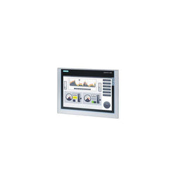
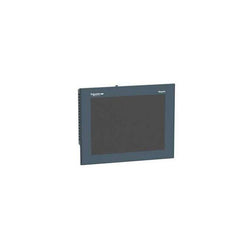
| Product Description | SIMATIC HMI TP700 Comfort, Comfort Panel, touch operation, 7" widescreen TFT display, 16 million colors, PROFINET interface, MPI/PROFIBUS DP interface, 12 MB configuration memory, Windows CE 6.0, configurable from WinCC Comfort V11 |
| Product family | Comfort Panels standard devices |
| Product Lifecycle (PLM) | PM300:Active Product |
| Additional Product Information | |
| EAN | 4025515079026 |
| UPC | 040892783421 |
| Commodity Code | 85371098 |
| LKZ_FDB/ CatalogID | ST80.1N |
| Product Group | 3403 |
| Group Code | R141 |
| Country of origin | Germany |
| SCIP number | 0b4dac5f-f856-4a04-a078-6d75cd7fbb9e |
| Delivery information | |
| Net Weight (lb) | 3.523 lb |
| Package size unit of measure | Inch |
| Packaging Quantity | 1 |

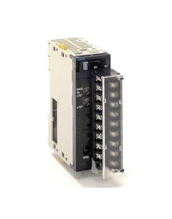
CPU with built-in EtherNet/IP port, 10K steps program, 32K words data memory, 32K words x 1 bank EM, 2560 I/O max, option port for RS-232C/485, USB programming port, 3 expansion racks max

| Product | |
| Article Number (Market Facing Number) | 6ES71346GD010BA1 | 6ES71346GD010BA1 |
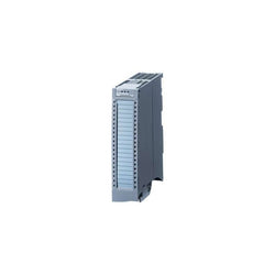
| Product Description | SIMATIC ET 200SP, ANALOG INPUT MODULE, AI 4XI 2-/4-WIRE STANDARD, PACKING UNIT: 1 PIECE, FITS TO BU-TYPE A0, A1, COLOR CODE CC03, MODULE DIAGNOSIS, 16BIT, +/-0,3% |
| Product family | Analog input modules |
| Product Lifecycle (PLM) | PM300:Active Product |
| Additional Product Information | |
| EAN | 4047623409212 |
| UPC | 804766680885 |
| Commodity Code | 85389091 |
| LKZ_FDB/ CatalogID | ST76 |
| Product Group | 4520 |
| Group Code | R151 |
| Country of origin | Germany |
| SCIP number | Not available |
| Delivery information | |
| Net Weight (lb) | 0.088 lb |
| Package size unit of measure | Inch |
| Packaging Quantity | 1 |
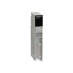
Analog input unit, 8 x inputs 1 to 5 V, 0 to 5 V, 0 to 10 V, -10 to 10 V, 4 to 20 mA, resolution 1:4000 / 8000, screw terminal

Variable Speed Drive Altivar ATV320 - 7.5kW - 380...500V - 3 Phase - book
| Product | |
| Article Number (Market Facing Number) | 6ES75325HF000AB0 | 6ES75325HF000AB0 |
| Product Description | SIMATIC S7-1500, analog output module AQ8xU/I HS, 16-bit resolution accuracy 0.3%, 8 channels in groups of 8, diagnostics; substitute value 8 channels in 0.125 ms oversampling; the module supports the safety-oriented shutdown of load groups up to SIL2 according to EN IEC 62061:2021 and Category 3 / PL d according to EN ISO 13849-1:2015. delivery including infeed element, shielding bracket and shield terminal: front connector (screw terminals or push-in) to be ordered separately |
| Product family | SM 532 analog output modules |
| Product Lifecycle (PLM) | PM300:Active Product |
| Additional Product Information | |
| EAN | 4025515080176 |
| UPC | 887621139179 |
| Commodity Code | 85389091 |
| LKZ_FDB/ CatalogID | ST73 |
| Product Group | 4501 |
| Group Code | R151 |
| Country of origin | Germany |
| SCIP number | Not available |
| Delivery information | |
| Net Weight (lb) | 0.935 lb |
| Package size unit of measure | Inch |
| Packaging Quantity | 1 |
| Product | |
| Article Number (Market Facing Number) | 6AV21232JB030AX0 | 6AV21232JB030AX0 |
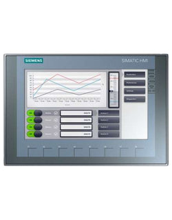
| Product Description | SIMATIC HMI, KTP900 Basic, Basic Panel, Key/touch operation, 9" TFT display, 65536 colors, PROFINET interface, configurable from WinCC Basic V13/ STEP 7 Basic V13, contains open-source software, which is provided free of charge see enclosed CD |
| Product family | Standard devices 2nd Generation |
| Product Lifecycle (PLM) | PM300:Active Product |
| Additional Product Information | |
| EAN | 4034106029234 |
| UPC | 887621830274 |
| Commodity Code | 85371091 |
| LKZ_FDB/ CatalogID | ST80.1J |
| Product Group | 2262 |
| Group Code | R141 |
| Country of origin | China |
| SCIP number | Not available |
| Delivery information | |
| Net Weight (lb) | 3.049 lb |
| Package size unit of measure | Inch |
| Packaging Quantity | 1 |
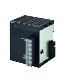
Power supply unit, 100-240 VAC, output capacity: 25 W, with RUN output

| Product | |
| Article Number (Market Facing Number) | 3TK28251BB40 | 3TK28251BB40 |
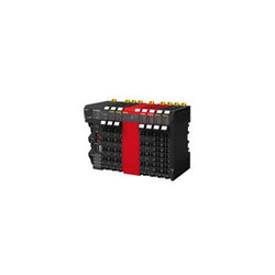
| Product Description | SIRIUS safety relay with relay enabling circuits (EC) 24 V DC, 45 mm overall width Screw terminal EC instantaneous: 3 NO EC delayed: 0 NO SC: 2 NC Autostart/monitored start Basic device Maximum achieved SIL: 3, PL: E |
| Product family | Not available |
| Product Lifecycle (PLM) | PM490:Start of final year of support |
| Additional Product Information | |
| EAN | 4011209380691 |
| UPC | 754554483412 |
| Commodity Code | 85364900 |
| LKZ_FDB/ CatalogID | CC-IC10 |
| Product Group | 5837 |
| Group Code | R711 |
| Country of origin | Germany |
| SCIP number | Not available |
| Delivery information | |
| Net Weight (lb) | 0.891 lb |
| Package size unit of measure | Inch |
| Packaging Quantity | 1 |
ACS550, 20HP, 3-Phase, 380-480V (Input), Nema 1 Enclosure, Variable Frequency Drives
Power Supply module Modicon Quantum - 115 V/230 V AC - summable or standalone

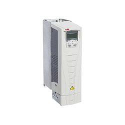
Variable Frequency Drive, 400 – 480 VAC 3 Phase Input, 480 VAC 3 Phase Output, 14.0 Amps
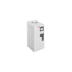
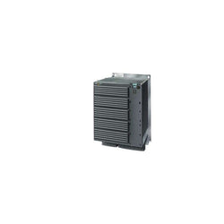
DRIVE 22kW/45A, IP55, EMC class C2
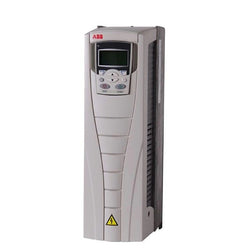
AC DRIVE ACS550 SERIES, IEC INSTALLATION AND COMPLIANCE, THREE-PHASE, 380-480 VAC, 50/60 HZ, 23 A, 11 KW, UL TYPE/NEMA 1

Input, Output (I/O) Module DIN Rail 100 ~ 240VAC, 24VDC

TeSys U standard power base, 3 poles (3NO), 12A/690V, to be completed with a control unit LUC to form a TeSys U starter controller, for 3-phase motor applications up to 5.5kW@400V. Base composed of power contacts, control coil, rotary handle, with a modular design for additional modules to form a "all in one" starter controller with basic or advanced protection and control functions. It is equipped with a control terminal block, and blanking shutters covering the empty cavities. It provides a high breaking capacity Icu 50kA@400V, start-stop control guaranteed for 3600 cycles/hour. Very compact (45mm width), DIN-rail mounting and screw fixing, with a padlockable rotary handle. Certified when used in conjunction with a LUC control unit (IEC, UL, CSA, CCC, EAC, Marine).
Main
| Characteristic | Value(s) |
|---|---|
| Range | TeSys |
| product name | TeSys Ultra |
| Device short name | LUB |
| Product or Component Type | Non reversing power base |
| Device Application | Motor control Motor protection |
| Poles description | 3P |
| Suitability for isolation | Yes |
| [Ue] rated operational voltage | 690 V AC power circuit |
| Network frequency | 40...60 Hz |
| [Ith] conventional free air thermal current | 12 A |
| [Ie] rated operational current | 12 A <= 440 V 12 A 500 V 9 A 690 V |
| Utilisation category | AC-43 AC-44 AC-41 |
| [Ics] rated service breaking capacity | 50 kA 230 V 50 kA 440 V 10 kA 500 V 4 kA 690 V |
| Auxiliary contact composition | 1 NO + 1 NC |
| Auxiliary contacts type | Linked contacts 1 NO + 1 NC) IEC 60947-4-1 Mirror contact 1 NC) IEC 60947-1 |
| [Uc] control circuit voltage | 24 V AC 50/60 Hz 24 V DC 48...72 V AC 50/60 Hz 48...72 V DC 110...240 V AC 50/60 Hz 110...220 V DC |
Complementary
| Characteristic | Value(s) |
|---|---|
| Typical current consumption | 130 mA 24 V DC I maximum while closing with LUCA, LUCB, LUCC, LUCD 140 mA 24 V AC I maximum while closing with LUCA, LUCB, LUCC, LUCD 150 mA 24 V DC I maximum while closing with LUCM 280 mA 110...220 V DC I maximum while closing with LUCA, LUCB, LUCC, LUCD 280 mA 110...240 V AC I maximum while closing with LUCA, LUCB, LUCC, LUCD 280 mA 48...72 V AC I maximum while closing with LUCA, LUCB, LUCC, LUCD 280 mA 48...72 V DC I maximum while closing with LUCA, LUCB, LUCC, LUCD 35 mA 110...220 V DC I rms sealed with LUCA, LUCB, LUCC, LUCD 35 mA 110...240 V AC I rms sealed with LUCA, LUCB, LUCC, LUCD 35 mA 48...72 V AC I rms sealed with LUCA, LUCB, LUCC, LUCD 35 mA 48...72 V DC I rms sealed with LUCA, LUCB, LUCC, LUCD 60 mA 24 V DC I rms sealed with LUCA, LUCB, LUCC, LUCD 70 mA 24 V AC I rms sealed with LUCA, LUCB, LUCC, LUCD 70 mA 24 V DC I rms sealed with LUCM |
| Heat dissipation | 2 W control circuit with LUCA, LUCB, LUCC, LUCD 1.7 W control circuit with LUCM |
| Safety reliability level | B10d = 1369863 cycles contactor with nominal load EN/ISO 13849-1 B10d = 20000000 cycles contactor with mechanical load EN/ISO 13849-1 |
| Operating time | 35 ms opening with LUCA, LUCB, LUCC, LUCD, LUCM control circuit 50 ms >= 72 V closing with LUCA, LUCB, LUCC, LUCD control circuit 60 ms 48 V closing with LUCA, LUCB, LUCC, LUCD control circuit 70 ms 24 V closing with LUCA, LUCB, LUCC, LUCD control circuit 75 ms closing with LUCM control circuit |
| Mechanical durability | 15 Mcycles |
| Maximum operating rate | 3600 cyc/h |
| Product Certifications | CE UL CSA CCC EAC ASEFA ATEX Marine |
| Standards | EN 60947-6-2 IEC 60947-6-2 UL 60947-4-1, with phase barrier CSA C22.2 No 60947-4-1, with phase barrier |
| [Ui] rated insulation voltage | 690 V IEC 60947-6-2 3) 600 V UL 60947-4-1 600 V CSA C22.2 No 60947-4-1 |
| [Uimp] rated impulse withstand voltage | 6 kVIEC 60947-6-2 |
| Safe separation of circuit | 400 V SELV between the control and auxiliary circuits IEC 60947-1 appendix N 400 V SELV between the control or auxiliary circuit and the main circuit IEC 60947-1 appendix N |
| Fixing mode | Clipped (DIN rail) Screw-fixed (plate) |
| Connections - terminals | Control circuit screw clamp terminals 1 0.0005â¦0.002 in² (0.34â¦1.5 mm²) flexible with cable end Control circuit screw clamp terminals 1 0.001â¦0.002 in² (0.75â¦1.5 mm²) flexible without cable end Control circuit screw clamp terminals 1 0.001â¦0.002 in² (0.75â¦1.5 mm²) rigid Control circuit screw clamp terminals 2 0.0005â¦0.002 in² (0.34â¦1.5 mm²) flexible with cable end Control circuit screw clamp terminals 2 0.001â¦0.002 in² (0.75â¦1.5 mm²) flexible without cable end Control circuit screw clamp terminals 2 0.001â¦0.002 in² (0.75â¦1.5 mm²) rigid Power circuit screw clamp terminals 1 0.002â¦0.02 in² (1â¦10 mm²) rigid Power circuit screw clamp terminals 1 0.002â¦0.009 in² (1â¦6 mm²) flexible with cable end Power circuit screw clamp terminals 1 0.004â¦0.02 in² (2.5â¦10 mm²) flexible without cable end Power circuit screw clamp terminals 2 0.002â¦0.009 in² (1â¦6 mm²) flexible with cable end Power circuit screw clamp terminals 2 0.002â¦0.009 in² (1â¦6 mm²) rigid Power circuit screw clamp terminals 2 0.002â¦0.009 in² (1.5â¦6 mm²) flexible without cable end |
| Tightening torque | Control circuit: 7.08â¦10.6 lbf.in (0.8â¦1.2 N.m) flat screwdriver 0.2 in (5 mm) Control circuit: 7.08â¦10.6 lbf.in (0.8â¦1.2 N.m) Philips no 1 screwdriver 0.2 in (5 mm) Power circuit: 16.8â¦22.1 lbf.in (1.9â¦2.5 N.m) flat screwdriver 0.2 in (6 mm) Power circuit: 16.8â¦22.1 lbf.in (1.9â¦2.5 N.m) Philips No 2 screwdriver 0.2 in (6 mm) Power circuit: 16.8â¦22.1 lbf.in (1.9â¦2.5 N.m) pozidriv No 2 screwdriver 0.2 in (6 mm) |
| Width | 1.8 in (45 mm) |
| Height | 6.06 in (154 mm) |
| Depth | 5.0 in (126 mm) |
| Product Weight | 2.0 lb(US) (0.9 kg) |
| Compatibility code | LUB |
| Product | |
| Article Number (Market Facing Number) | 6SL32240BE411UA0 | 6SL32240BE411UA0 |
| Product Description | ***spare part*** SINAMICS G120 PM240 Power Module unfiltered with integrated braking chopper 380-480 V 3 AC +10/-10% 47-63 Hz power high overload: 110 kW at 160% 3 s,136% 57 s,100% 240 s ambient temperature 0 to +50 °C power low overload: 132 kW At 150% 3 s, 110% 57 s, 100% 240 s ambient temperature 0 to +40 °C 634 x 350 x 316 (HxWxD), FSF degree of protection IP20 without Control Unit and BOP |
| Product family | Not available |
| Product Lifecycle (PLM) | PM410:Product cancellation |
| Additional Product Information | |
| EAN | 4019169456975 |
| UPC | 662643434613 |
| Commodity Code | 85044086 |
| LKZ_FDB/ CatalogID | D11.1SD |
| Product Group | 9486 |
| Group Code | R2S3 |
| Country of origin | Germany |
| SCIP number | b8e28b51-14a4-4930-9ee5-9c44cb001c64 |
| Delivery information | |
| Net Weight (lb) | 88.185 lb |
| Package size unit of measure | Inch |
| Packaging Quantity | 1 |

Main
| Characteristic | Value(s) |
|---|---|
| Range of Product | Altivar 71 |
| Product or Component Type | Variable speed drive |
| Product Specific Application | Complex, high-power machines |
| Component name | ATV71 |
| Motor power kW | 30 kW, 3 phase 380...480 V |
| Maximum Horse Power Rating | 40 hp, 3 phase 380...480 V |
| Maximum motor cable length | 328.08 ft (100 m) shielded cable 656.2 ft (200 m) unshielded cable |
| power supply voltage | 380...480 V - 15...10 % |
| Phase | 3 phase |
| Line current | 56 A 480 V 3 phase 30 kW / 40 hp 66 A 380 V 3 phase 30 kW / 40 hp |
| EMC filter | Integrated |
| Assembly style | With heat sink |
| Apparent power | 43.4 kVA 380 V 3 phase 30 kW / 40 hp |
| Prospective line Isc | 22 kA 3 phase |
| Nominal output current | 52 A 4 kHz 460 V 3 phase 30 kW / 40 hp 66 A 4 kHz 380 V 3 phase 30 kW / 40 hp |
| Maximum transient current | 109 A 2 s 3 phase 30 kW / 40 hp 99 A 60 s 3 phase 30 kW / 40 hp |
| Output frequency | 0.1â¦599 Hz |
| Nominal switching frequency | 4 kHz |
| Switching frequency | 1...16 kHz adjustable 4...16 kHz with derating factor |
| Asynchronous motor control profile | Sensorless flux vector control (SFVC) (voltage or current vector) Voltage/frequency ratio (2 or 5 points) Flux vector control (FVC) with sensor (current vector) ENA (Energy adaptation) system for unbalanced loads |
| Type of polarization | No impedance Modbus |
Complementary
| Characteristic | Value(s) |
|---|---|
| Product destination | Asynchronous motors Synchronous motors |
| power supply voltage limits | 323â¦528 V |
| power supply frequency | 50...60 Hz - 5...5 % |
| power supply frequency limits | 47.5...63 Hz |
| Speed range | 1â¦100 asynchronous motor in open-loop mode, without speed feedback 1â¦1000 asynchronous motor in closed-loop mode with encoder feedback 1â¦50 synchronous motor in open-loop mode, without speed feedback |
| Speed accuracy | +/- 0.01 % of nominal speed in closed-loop mode with encoder feedback 0.2 Tn to Tn +/- 10 % of nominal slip without speed feedback 0.2 Tn to Tn |
| Torque accuracy | +/- 15 % in open-loop mode, without speed feedback +/- 5 % in closed-loop mode with encoder feedback |
| Transient overtorque | 170 % +/- 10 % 60 s every 10 minutes 220 % +/- 10 % 2 s |
| Braking torque | <= 150 % with braking or hoist resistor 30 % without braking resistor |
| Synchronous motor control profile | Vector control without speed feedback |
| Regulation loop | Adjustable PI regulator |
| Motor slip compensation | Suppressable Adjustable Not available in voltage/frequency ratio (2 or 5 points) Automatic whatever the load |
| diagnostic | 1 LED (red) for drive voltage |
| Output voltage | <= power supply voltage |
| Insulation | Electrical between power and control |
| type of cable for mounting in an enclosure | With a NEMA Type1 kit 3 UL 508 cable 104 °F (40 °C), copper 75 °C / PVC With an IP21 or an IP31 kit 3 IEC cable 104 °F (40 °C), copper 70 °C / PVC Without mounting kit 1 IEC cable 113 °F (45 °C), copper 70 °C / PVC Without mounting kit 1 IEC cable 113 °F (45 °C), copper 90 °C / XLPE/EPR |
| Electrical connection | Terminal 2.5 mm², AWG 14 AI1-/AI1+, AI2, AO1, R1A, R1B, R1C, R2A, R2B, LI1...LI6, PWR) Terminal 50 mm², AWG 1/0 L1/R, L2/S, L3/T, U/T1, V/T2, W/T3, PC/-, PO, PA/+, PA, PB) |
| Tightening torque | 5.3 lbf.in (0.6 N.m) AI1-/AI1+, AI2, AO1, R1A, R1B, R1C, R2A, R2B, LI1...LI6, PWR) 106.2 lbf.in (12 N.m), 102.2 lb.in L1/R, L2/S, L3/T, U/T1, V/T2, W/T3, PC/-, PO, PA/+, PA, PB) |
| Supply | Internal supply for reference potentiometer (1 to 10 kOhm) 10.5 V DC +/- 5 %, <10 mA overload and short-circuit protection Internal supply 24 V DC 21â¦27 V), <200 mA overload and short-circuit protection |
| Analogue input number | 2 |
| Analogue input type | AI1-/Al1+ bipolar differential voltage +/- 10 V DC 24 V max 11 bits + sign AI2 software-configurable current 0...20 mA 242 Ohm 11 bits AI2 software-configurable voltage 0...10 V DC 24 V max 30000 Ohm 11 bits |
| input sampling time | 2 ms +/- 0.5 ms AI1-/Al1+) - analog 2 ms +/- 0.5 ms Al2) - analog 2 ms +/- 0.5 ms LI1...LI5) - discrete 2 ms +/- 0.5 ms LI6)if configured as logic input - discrete |
| Response time | <= 100 ms in STO (Safe Torque Off) AO1 2 ms +/- 0.5 ms analog R1A, R1B, R1C 7 ms +/- 0.5 ms discrete R2A, R2B 7 ms +/- 0.5 ms discrete |
| absolute accuracy precision | +/- 0.6 % AI1-/Al1+) for a temperature variation 60 °C +/- 0.6 % AI2) for a temperature variation 60 °C +/- 1 % AO1) for a temperature variation 60 °C |
| Linearity error | +/- 0.15 % of maximum value AI1-/Al1+, AI2) +/- 0.2 % AO1) |
| Analogue output number | 1 |
| Analogue output type | AO1 software-configurable logic output 10 V 20 mA AO1 software-configurable current 0...20 mA 500 Ohm 10 bits AO1 software-configurable voltage 0...10 V DC 470 Ohm 10 bits |
| Discrete output number | 2 |
| Discrete output type | Configurable relay logic R1A, R1B, R1C) NO/NC - 100000 cycles Configurable relay logic R2A, R2B) NO - 100000 cycles |
| Minimum switching current | 3 mA 24 V DC configurable relay logic |
| Maximum switching current | R1, R2 2 A 250 V AC inductive, cos phi = 0.4 R1, R2 2 A 30 V DC inductive, cos phi = 0.4 R1, R2 5 A 250 V AC resistive, cos phi = 1 R1, R2 5 A 30 V DC resistive, cos phi = 1 |
| Discrete input number | 7 |
| Discrete input type | LI1...LI5 programmable 24 V DC level 1 PLC 3500 Ohm LI6 switch-configurable 24 V DC level 1 PLC 3500 Ohm LI6 switch-configurable PTC probe 0â¦6 1500 Ohm PWR safety input 24 V DC 1500 Ohm ISO 13849-1 level d |
| Discrete input logic | Negative logic (sink) LI1...LI5), > 16 V, < 10 V Positive logic (source) LI1...LI5), < 5 V, > 11 V Negative logic (sink) LI6)if configured as logic input, > 16 V, < 10 V Positive logic (source) LI6)if configured as logic input, < 5 V, > 11 V |
| Acceleration and deceleration ramps | Linear adjustable separately from 0.01 to 9000 s Automatic adaptation of ramp if braking capacity exceeded, by using resistor S, U or customized |
| Braking to standstill | By DC injection |
| Protection type | Against exceeding limit speed drive Against input phase loss drive Break on the control circuit drive Input phase breaks drive Line supply overvoltage drive Line supply undervoltage drive Overcurrent between output phases and earth drive Overheating protection drive Overvoltages on the DC bus drive Short-circuit between motor phases drive Thermal protection drive Motor phase break motor Power removal motor Thermal protection motor |
| Insulation resistance | > 1 mOhm 500 V DC for 1 minute to earth |
| Frequency resolution | Analog input 0.024/50 Hz Display unit 0.1 Hz |
| Communication Port Protocol | Modbus CANopen |
| Connector type | 1 RJ45 on front face)Modbus 1 RJ45 on terminal)Modbus Male SUB-D 9 on RJ45CANopen |
| Physical interface | 2-wire RS 485 Modbus |
| Transmission frame | RTU Modbus |
| Transmission rate | 4800 bps, 9600 bps, 19200 bps, 38.4 Kbps Modbus on terminal 9600 bps, 19200 bps Modbus on front face 20 kbps, 50 kbps, 125 kbps, 250 kbps, 500 kbps, 1 Mbps CANopen |
| Data format | 8 bits, 1 stop, even parity Modbus on front face 8 bits, odd even or no configurable parity Modbus on terminal |
| Number of addresses | 1â¦127 CANopen 1â¦247 Modbus |
| Method of access | Slave CANopen |
| Marking | CE |
| Operating position | Vertical +/- 10 degree |
| Height | 21.7 in (550 mm) |
| Depth | 10.5 in (266 mm) |
| Width | 9.4 in (240 mm) |
| Product Weight | 81.6 lb(US) (37 kg) |
| Functionality | Full |
| Specific application | Other applications |
| Option card | Communication card CC-Link Controller inside programmable card Communication card DeviceNet Communication card EtherNet/IP Communication card Fipio I/O extension card Communication card Interbus-S Interface card for encoder Communication card Modbus Plus Communication card Modbus TCP Communication card Modbus/Uni-Telway Overhead crane card Communication card Profibus DP Communication card Profibus DP V1 |

Touch screen HMI, 12.1 inch wide screen, TFT LCD, 24bit color, 1280x800 resolution, frame color : Black

Altivar Machine ATV320 range is an offer of variable speed drives designed for Original Equipment Manufacturers (OEMs). Its compact form factor allows vertical stacking of drives inside machine frames. It works at a rated power up to 4kW / 5hp and a rated voltage from 200V to 240V AC. Its robust design with IEC 60721-3-3 class 3C3 coated printed circuit boards allows to extend machine availability in harsh environmental conditions, for example at ambient temperatures of up to 60°C without the need of additional cooling. It incorporates functions suitable for the most common applications, including torque and speed accuracy at very low speed, high dynamic performance with flux vector control without sensor and extended frequency range for high-speed motors. It also incorporates parallel connection of motors and special drives using the voltage/frequency ratio and static speed accuracy and energy saving for open-loop synchronous motors. It weighs 2.2kg and its dimensions are 140mm wide, 184mm high, 158mm deep. The drive software includes 5 safety functions that help machines meet safety requirements, whether or not they are used in conjunction with a Preventa safety module. These safety functions are configured using SoMove software. Altivar Machine ATV320 was designed for Original Equipment Manufacturers (OEMs) that meets simple and advanced application requirements covered for packaging, material handling, textile, material working, mechanical actuators and hoisting. It conforms to IEC, UL, TUV, KC and other international standards. Mounting accessories and external options (braking resistors, line chokes, motor chokes, additional EMC filters) are available with Altivar Machine ATV320 drives. The type of external accessories and options depends on the drive rating. The product is delivered in three packages. It is designed to be mounted in vertical position (+/- 10 °) on a panel, thanks to 4 fixing holes. It is fully integrated inside Schneider Electricâs EcoStruxure Machine through DTM. It is possible to configure, control, and diagnose ATV320 drives directly in SoMachine and SoMove software by means of the same software brick (DTM).
Main
| Characteristic | Value(s) |
|---|---|
| Range of Product | Altivar Machine ATV320 |
| Product or Component Type | Variable speed drive |
| Product Specific Application | Complex machines |
| Variant | Standard version |
| Format of the drive | Compact |
| Mounting Mode | Wall mount |
| Communication Port Protocol | Modbus serial CANopen |
| Option card | communication module, CANopen communication module, EtherCAT communication module, Profibus DP V1 communication module, PROFINET communication module, Ethernet Powerlink communication module, EtherNet/IP communication module, DeviceNet |
| [Us] rated supply voltage | 200...240 V - 15...10 % |
| nominal output current | 17.5 A |
| Motor power kW | 4.0 kW heavy duty |
| EMC filter | Without EMC filter |
| IP degree of protection | IP20 |
Complementary
| Characteristic | Value(s) |
|---|---|
| Discrete input number | 7 |
| Discrete input type | STO safe torque off, 24 V DC1.5 kOhm DI1...DI6 logic inputs, 24 V DC 30 V) DI5 programmable as pulse input 0â¦30 kHz, 24 V DC 30 V) |
| Discrete input logic | Positive logic (source) Negative logic (sink) |
| Discrete output number | 3 |
| Discrete output type | Open collector DQ+ 0â¦1 kHz 30 V DC 100 mA Open collector DQ- 0â¦1 kHz 30 V DC 100 mA |
| Analogue input number | 3 |
| Analogue input type | AI1 voltage 0...10 V DC 30 kOhm 10 bits AI2 bipolar differential voltage +/- 10 V DC 30 kOhm 10 bits AI3 current 0...20 mA (or 4-20 mA, x-20 mA, 20-x mA or other patterns by configuration) 250 Ohm 10 bits |
| Analogue output number | 1 |
| Analogue output type | Software-configurable current AQ1 0...20 mA 800 Ohm 10 bits Software-configurable voltage AQ1 0...10 V DC 470 Ohm 10 bits |
| Relay output type | Configurable relay logic R1A 1 NO 100000 cycles Configurable relay logic R1B 1 NC 100000 cycles Configurable relay logic R1C Configurable relay logic R2A 1 NO 100000 cycles Configurable relay logic R2C |
| Maximum switching current | Relay output R1A, R1B, R1C resistive, cos phi = 1 3 A 250 V AC Relay output R1A, R1B, R1C resistive, cos phi = 1 3 A 30 V DC Relay output R1A, R1B, R1C, R2A, R2C inductive, cos phi = 0.4 7 ms 2 A 250 V AC Relay output R1A, R1B, R1C, R2A, R2C inductive, cos phi = 0.4 7 ms 2 A 30 V DC Relay output R2A, R2C resistive, cos phi = 1 5 A 250 V AC Relay output R2A, R2C resistive, cos phi = 1 5 A 30 V DC |
| Minimum switching current | Relay output R1A, R1B, R1C, R2A, R2C 5 mA 24 V DC |
| Method of access | Slave CANopen |
| 4 quadrant operation possible | True |
| Asynchronous motor control profile | Voltage/frequency ratio, 5 points Flux vector control without sensor, standard Voltage/frequency ratio - Energy Saving, quadratic U/f Flux vector control without sensor - Energy Saving Voltage/frequency ratio, 2 points |
| Synchronous motor control profile | Vector control without sensor |
| Maximum output frequency | 0.599 kHz |
| Acceleration and deceleration ramps | Linear U S CUS Ramp switching Acceleration/deceleration ramp adaptation Acceleration/deceleration automatic stop with DC injection |
| Motor slip compensation | Automatic whatever the load Adjustable 0...300 % Not available in voltage/frequency ratio (2 or 5 points) |
| Switching frequency | 2...16 kHz adjustable 4...16 kHz with derating factor |
| Nominal switching frequency | 4 kHz |
| Braking to standstill | By DC injection |
| Brake chopper integrated | True |
| Line current | 23.8 A 200 V heavy duty) 19.9 A 240 V heavy duty) |
| Maximum Input Current per Phase | 23.8 A |
| Maximum output voltage | 240 V |
| Apparent power | 8.3 kVA 240 V heavy duty) |
| Network Frequency | 50-60 Hz |
| Relative symmetric network frequency tolerance | 5 % |
| Prospective line Isc | 5 kA |
| Base load current at high overload | 17.0 A |
| Power dissipation in W | Fan 140 W 200 V 4 kHz |
| With safety function Safely Limited Speed (SLS) | True |
| With safety function Safe brake management (SBC/SBT) | False |
| With safety function Safe Operating Stop (SOS) | False |
| With safety function Safe Position (SP) | False |
| With safety function Safe programmable logic | False |
| With safety function Safe Speed Monitor (SSM) | False |
| With safety function Safe Stop 1 (SS1) | True |
| With sft fct Safe Stop 2 (SS2) | False |
| With safety function Safe torque off (STO) | True |
| With safety function Safely Limited Position (SLP) | False |
| With safety function Safe Direction (SDI) | False |
| Protection type | Input phase breaks drive Overcurrent between output phases and earth drive Overheating protection drive Short-circuit between motor phases drive Thermal protection drive |
| Width | 5.5 in (140 mm) |
| Height | 7.2 in (184.0 mm) |
| Depth | 6.2 in (158.0 mm) |
| Product Weight | 4.9 lb(US) (2.2 kg) |
| Transient overtorque | 170â¦200 % of nominal motor torque |
advanced touchscreen panel 640 x 480 pixels VGA- 10.4" TFT - 96 MB

Main
| Characteristic | Value(s) |
|---|---|
| Range of Product | Altivar 71 |
| Product or Component Type | Variable speed drive |
| Product Specific Application | Complex, high-power machines |
| Component name | ATV71 |
| Motor power kW | 5.5 kW, 3 phase 380...480 V |
| Maximum Horse Power Rating | 7.5 hp, 3 phase 380...480 V |
| Maximum motor cable length | 164.04 ft (50 m) shielded cable 328.08 ft (100 m) unshielded cable |
| power supply voltage | 380...480 V - 15...10 % |
| Phase | 3 phase |
| Line current | 17 A 480 V 3 phase 5.5 kW / 7.5 hp 20.3 A 380 V 3 phase 5.5 kW / 7.5 hp |
| EMC filter | Integrated |
| Assembly style | With heat sink |
| Apparent power | 13.4 kVA 380 V 3 phase 5.5 kW / 7.5 hp |
| Prospective line Isc | 22 kA 3 phase |
| Nominal output current | 11 A 4 kHz 460 V 3 phase 5.5 kW / 7.5 hp 14.3 A 4 kHz 380 V 3 phase 5.5 kW / 7.5 hp |
| Maximum transient current | 21.5 A 60 s 3 phase 5.5 kW / 7.5 hp 23.6 A 2 s 3 phase 5.5 kW / 7.5 hp |
| Output frequency | 0.1â¦599 Hz |
| Nominal switching frequency | 4 kHz |
| Switching frequency | 1...16 kHz adjustable 4...16 kHz with derating factor |
| Asynchronous motor control profile | Sensorless flux vector control (SFVC) (voltage or current vector) Voltage/frequency ratio (2 or 5 points) ENA (Energy adaptation) system for unbalanced loads Flux vector control (FVC) with sensor (current vector) |
| Type of polarization | No impedance Modbus |
Complementary
| Characteristic | Value(s) |
|---|---|
| Product destination | Synchronous motors Asynchronous motors |
| power supply voltage limits | 323â¦528 V |
| power supply frequency | 50...60 Hz - 5...5 % |
| power supply frequency limits | 47.5...63 Hz |
| Speed range | 1â¦100 asynchronous motor in open-loop mode, without speed feedback 1â¦1000 asynchronous motor in closed-loop mode with encoder feedback 1â¦50 synchronous motor in open-loop mode, without speed feedback |
| Speed accuracy | +/- 0.01 % of nominal speed in closed-loop mode with encoder feedback 0.2 Tn to Tn +/- 10 % of nominal slip without speed feedback 0.2 Tn to Tn |
| Torque accuracy | +/- 15 % in open-loop mode, without speed feedback +/- 5 % in closed-loop mode with encoder feedback |
| Transient overtorque | 170 % +/- 10 % 60 s every 10 minutes 220 % +/- 10 % 2 s |
| Braking torque | <= 150 % with braking or hoist resistor 30 % without braking resistor |
| Synchronous motor control profile | Vector control without speed feedback |
| Regulation loop | Adjustable PI regulator |
| Motor slip compensation | Adjustable Suppressable Not available in voltage/frequency ratio (2 or 5 points) Automatic whatever the load |
| diagnostic | 1 LED (red) for drive voltage |
| Output voltage | <= power supply voltage |
| Insulation | Electrical between power and control |
| type of cable for mounting in an enclosure | With a NEMA Type1 kit 3 UL 508 cable 104 °F (40 °C), copper 75 °C / PVC With an IP21 or an IP31 kit 3 IEC cable 104 °F (40 °C), copper 70 °C / PVC Without mounting kit 1 IEC cable 113 °F (45 °C), copper 70 °C / PVC Without mounting kit 1 IEC cable 113 °F (45 °C), copper 90 °C / XLPE/EPR |
| Electrical connection | Terminal 2.5 mm², AWG 14 AI1-/AI1+, AI2, AO1, R1A, R1B, R1C, R2A, R2B, LI1...LI6, PWR) Terminal 6 mm², AWG 8 L1/R, L2/S, L3/T, U/T1, V/T2, W/T3, PC/-, PO, PA/+, PA, PB) |
| Tightening torque | 5.3 lbf.in (0.6 N.m) AI1-/AI1+, AI2, AO1, R1A, R1B, R1C, R2A, R2B, LI1...LI6, PWR) 26.6 lbf.in (3 N.m), 26.5 lb.in L1/R, L2/S, L3/T, U/T1, V/T2, W/T3, PC/-, PO, PA/+, PA, PB) |
| Supply | Internal supply for reference potentiometer (1 to 10 kOhm) 10.5 V DC +/- 5 %, <10 mA overload and short-circuit protection Internal supply 24 V DC 21â¦27 V), <200 mA overload and short-circuit protection |
| Analogue input number | 2 |
| Analogue input type | AI1-/Al1+ bipolar differential voltage +/- 10 V DC 24 V max 11 bits + sign AI2 software-configurable current 0...20 mA 242 Ohm 11 bits AI2 software-configurable voltage 0...10 V DC 24 V max 30000 Ohm 11 bits |
| input sampling time | 2 ms +/- 0.5 ms AI1-/Al1+) - analog 2 ms +/- 0.5 ms Al2) - analog 2 ms +/- 0.5 ms LI1...LI5) - discrete 2 ms +/- 0.5 ms LI6)if configured as logic input - discrete |
| Response time | <= 100 ms in STO (Safe Torque Off) AO1 2 ms +/- 0.5 ms analog R1A, R1B, R1C 7 ms +/- 0.5 ms discrete R2A, R2B 7 ms +/- 0.5 ms discrete |
| absolute accuracy precision | +/- 0.6 % AI1-/Al1+) for a temperature variation 60 °C +/- 0.6 % AI2) for a temperature variation 60 °C +/- 1 % AO1) for a temperature variation 60 °C |
| Linearity error | +/- 0.15 % of maximum value AI1-/Al1+, AI2) +/- 0.2 % AO1) |
| Analogue output number | 1 |
| Analogue output type | AO1 software-configurable logic output 10 V 20 mA AO1 software-configurable current 0...20 mA 500 Ohm 10 bits AO1 software-configurable voltage 0...10 V DC 470 Ohm 10 bits |
| Discrete output number | 2 |
| Discrete output type | Configurable relay logic R1A, R1B, R1C) NO/NC - 100000 cycles Configurable relay logic R2A, R2B) NO - 100000 cycles |
| Minimum switching current | 3 mA 24 V DC configurable relay logic |
| Maximum switching current | R1, R2 2 A 250 V AC inductive, cos phi = 0.4 R1, R2 2 A 30 V DC inductive, cos phi = 0.4 R1, R2 5 A 250 V AC resistive, cos phi = 1 R1, R2 5 A 30 V DC resistive, cos phi = 1 |
| Discrete input number | 7 |
| Discrete input type | LI1...LI5 programmable 24 V DC level 1 PLC 3500 Ohm LI6 switch-configurable 24 V DC level 1 PLC 3500 Ohm LI6 switch-configurable PTC probe 0â¦6 1500 Ohm PWR safety input 24 V DC 1500 Ohm ISO 13849-1 level d |
| Discrete input logic | Negative logic (sink) LI1...LI5), > 16 V, < 10 V Positive logic (source) LI1...LI5), < 5 V, > 11 V Negative logic (sink) LI6)if configured as logic input, > 16 V, < 10 V Positive logic (source) LI6)if configured as logic input, < 5 V, > 11 V |
| Acceleration and deceleration ramps | Linear adjustable separately from 0.01 to 9000 s Automatic adaptation of ramp if braking capacity exceeded, by using resistor S, U or customized |
| Braking to standstill | By DC injection |
| Protection type | Against exceeding limit speed drive Against input phase loss drive Break on the control circuit drive Input phase breaks drive Line supply overvoltage drive Line supply undervoltage drive Overcurrent between output phases and earth drive Overheating protection drive Overvoltages on the DC bus drive Short-circuit between motor phases drive Thermal protection drive Motor phase break motor Power removal motor Thermal protection motor |
| Insulation resistance | > 1 mOhm 500 V DC for 1 minute to earth |
| Frequency resolution | Analog input 0.024/50 Hz Display unit 0.1 Hz |
| Communication Port Protocol | CANopen Modbus |
| Connector type | 1 RJ45 on front face)Modbus 1 RJ45 on terminal)Modbus Male SUB-D 9 on RJ45CANopen |
| Physical interface | 2-wire RS 485 Modbus |
| Transmission frame | RTU Modbus |
| Transmission rate | 4800 bps, 9600 bps, 19200 bps, 38.4 Kbps Modbus on terminal 9600 bps, 19200 bps Modbus on front face 20 kbps, 50 kbps, 125 kbps, 250 kbps, 500 kbps, 1 Mbps CANopen |
| Data format | 8 bits, 1 stop, even parity Modbus on front face 8 bits, odd even or no configurable parity Modbus on terminal |
| Number of addresses | 1â¦127 CANopen 1â¦247 Modbus |
| Method of access | Slave CANopen |
| Marking | CE |
| Operating position | Vertical +/- 10 degree |
| Height | 11.6 in (295 mm) |
| Depth | 7.4 in (187 mm) |
| Width | 6.9 in (175 mm) |
| Product Weight | 12.1 lb(US) (5.5 kg) |
| Functionality | Full |
| Specific application | Other applications |
| Option card | Communication card CC-Link Controller inside programmable card Communication card DeviceNet Communication card EtherNet/IP Communication card Fipio I/O extension card Communication card Interbus-S Interface card for encoder Communication card Modbus Plus Communication card Modbus TCP Communication card Modbus/Uni-Telway Overhead crane card Communication card Profibus DP Communication card Profibus DP V1 |
Controllers NX 16Pt, 24 VDC PNP Input