
 1 year warranty

Ordering
Popular Downloads
Dimensions
Technical
Technical UL/CSA
Environmental
Material Compliance
Certificates and Declarations
Container Information
External Classifications and Standards
Ordering
Popular Downloads
Dimensions
Technical
Technical UL/CSA
Environmental
Material Compliance
Certificates and Declarations
Container Information
External Classifications and Standards
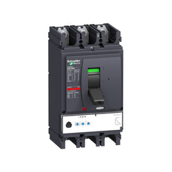
This Compact NSX400N is a complete 3P 3d fixed circuit breaker designed to optimize space and breaking capacity. It is an optimal choice for all standard and specific applications. The breaking capacity (Icu) is 50kA rms at 415VAC 50/60Hz. The operational voltage is 690VAC 50/60Hz. This product embeds an electronic Micrologic 2.3 trip unit, with 400A rating. Micrologic 2.3 trip unit provides adjustable long time and short time protections, and a fixed instantaneous protection. This 3 poles version (140mm x 255mm x 110mm) comes with a variety of optional functions and accessories. It is compliant with international standards (IEC 60947), CCC, EAC and marine specifications. Compact NSX400N is part of Schneider Electric EcoStruxure Power architecture.
Main
| Characteristic | Value(s) |
|---|---|
| Range | ComPact |
| product name | ComPact NSX |
| Range of product | ComPact NSX400...630 |
| Device short name | NSX400N |
| Product or component type | Circuit breaker |
| Device application | Distribution |
| Number of poles | 3P |
| Protected poles description | 3t |
| [In] rated current | 400 A at 40 °C |
| [Ue] rated operational voltage | 690 V AC 50/60 Hz |
| Network type | AC |
| Network frequency | 50/60 Hz |
| Suitability for isolation | Yes conforming to EN/IEC 60947-2 |
| Utilisation category | Category A |
| [Icu] rated ultimate short-circuit breaking capacity | 85 kA at 240 V AC 50/60 Hz conforming to UL 508 22 kA Icu at 525 V AC 50/60 Hz conforming to IEC 60947-2 85 kA Icu at 220/240 V AC 50/60 Hz conforming to IEC 60947-2 10 kA Icu at 660/690 V AC 50/60 Hz conforming to IEC 60947-2 30 kA Icu at 500 V AC 50/60 Hz conforming to IEC 60947-2 20 kA at 600 V AC 50/60 Hz conforming to UL 508 50 kA at 480 V AC 50/60 Hz conforming to UL 508 50 kA Icu at 380/415 V AC 50/60 Hz conforming to IEC 60947-2 42 kA Icu at 440 V AC 50/60 Hz conforming to IEC 60947-2 |
| Performance level | N 50 kA 415 V AC |
| Trip unit name | MicroLogic 2.3 |
| Trip unit technology | Electronic |
| Trip unit protection functions | LSoI |
| control type | Toggle |
| Circuit breaker mounting mode | Fixed |
Complementary
| Characteristic | Value(s) |
|---|---|
| [Ui] rated insulation voltage | 800 V AC 50/60 Hz |
| [Uimp] rated impulse withstand voltage | 8 kV |
| [Ics] rated service short-circuit breaking capacity | 11 kA at 525 V AC 50/60 Hz conforming to IEC 60947-2 85 kA at 220/240 V AC 50/60 Hz conforming to IEC 60947-2 10 kA at 660/690 V AC 50/60 Hz conforming to IEC 60947-2 50 kA at 380/415 V AC 50/60 Hz conforming to IEC 60947-2 30 kA at 500 V AC 50/60 Hz conforming to IEC 60947-2 42 kA at 440 V AC 50/60 Hz conforming to IEC 60947-2 |
| Mechanical durability | 15000 cycles |
| Electrical durability | 3000 cycles at 690 V In 6000 cycles at 690 V In/2 6000 cycles at 440 V In 12000 cycles at 440 V In/2 |
| Mounting support | Backplate |
| Upside connection | Front |
| Downside connection | Front |
| Connection pitch | 45 mm |
| Protection type | L : for overload protection (long time) So : for short time short-circuit protection with fixed delay I : for instantaneous short-circuit protection |
| Trip unit rating | 400 A at 40 °C |
| Long-time pick-up adjustment type Ir (thermal protection) | Adjustable 9 settings |
| [Ir] long-time protection pick-up adjustment range | 160...400 A |
| Long-time protection delay adjustment type tr | Fixed |
| [tr] long-time protection delay adjustment range | 16 s at 6 x Ir |
| Thermal memory | 20 minutes before and after tripping |
| Short-time protection pick-up adjustment type Isd | Adjustable 9 settings |
| [Isd] Short-time protection pick-up adjustment range | 1.5...10 x Ir |
| Short-time protection delay adjustment type tsd | Fixed |
| Instantaneous protection pick-up adjustment type Ii | Fixed |
| [Ii] instantaneous protection pick-up adjustment range | 4800 A |
| Earth-leakage protection | Without |
| Zone selective interlocking ZSI | Without |
| Number of slots for electrical auxiliaries | 6 slot(s) |
| Local signalling | Flashing LED (green) for ready to operate LED 105 % Ir (red) for overload LED 90 % Ir (orange) for overload |
| Width (W) | 140 mm |
| Height (H) | 255 mm |
| Depth (D) | 110 mm |
| Product weight | 6.05 kg |


digital input module - 12I - 24V DC sink - 1 wire
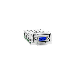
This Schneider Electric Altivar Profibus DP communication module has 1 x 9-way female SUB-D connector. It complies with PROFIBUS DP V1 standard. This communication module enables integration of your drive in your Profibus process control network. It is simple to install and remove from Altivar drives thanks to its modular withdrawable design. It is compatible with Altivar Process ATV600 (ATV630, ATV650)Altivar Process ATV900 (ATV930, ATV950), Lexium 32, Altivar Easy 610, Altivar 32, Altivar Machine ATV340 and Altivar Machine ATV320. Removable module allows last minute decisions on drive communication protocol, facilitates installation project management. It weighs 140g.
Main
| Characteristic | Value(s) |
|---|---|
| Range of Product | Altivar |
| Product or Component Type | Communication module |
| Accessory / separate part category | Communication accessories |
Complementary
| Characteristic | Value(s) |
|---|---|
| Product Compatibility | Lexium 32M |
| Range compatibility | Altivar 32 Altivar Machine ATV340 except Sercos drives Altivar Easy 610 Lexium 32 Altivar Process ATV900 Altivar Process ATV600 Altivar Machine ATV320 Altivar Process Modular |
| Communication Port Protocol | Profibus DP V1 |
| Electrical connection | 1 female connector SUB-D 9 |
| Transmission Rate | 9.6 kbps...12 Mbps |
| Addressing | 1...126 configurable by graphic terminal/SoMove software Configuration settings |
| Communication service | 4 configurable telegrams Mapping of the process data from the master Parameters management compliant with PROFIdrive V4.1 Several DP V1 messaging modes Drive profile native ATV32 IEC 61800-7-201 (CiA 402) |
| Display type | 1 LED RUN 1 LED bus fault (BF) |
| diagnostic function | Diagnostic data with VSD status Host drive handled from two masters (MS0 and MS1) Standard identification and maintenance requests |
| Bus profile | PROFIdrive CiA 402 |

This product is part of the Modicon TM3 range, an offer of expansion I/O modules for Modicon M221, M241, M251 and M262. The analogue I/O module provides 4 inputs and 2 outputs with 11bit + sign and 12bit input resolution. It is an I/O module with a rated supply voltage of 24V DC, a current consumption of 45mA, 55mA at 5V DC via bus connector, 55mA, 100mA at 24V DC via external supply. This product is capable of controlling variable speed drives or any device equipped with a current or voltage input. There is an insulation between input and supply at 1500V AC, input and internal logic at 500V AC, output and supply at 1500V AC and output and internal logic at 500V AC. It is furnished with removable screw terminal for electrical connection with 3.18mm pitch adjustment for inputs and supply. It is an IP20 rated product. Its dimensions are 23.6mm (Width) x 70mm (Depth) x 90mm (Height). It weighs 0.11kg. This product is certified by CE. It meets EN/IEC 61131-2 and EN/IEC 61010-2-201 standards. This module is compatible with Modicon M262, Modicon M241, Modicon M251 and Modicon M221 logic controller. It supports top hat type TH35-15, top hat type TH35-7.5 rail conforming to IEC 60715 and plate or panel with fixing kit mount. Modicon TM3 expansion modules have been designed with a simple interlocking assembly mechanism. A bus expansion connector is used to distribute data and the power supply when assembling the Modicon TM3 modules with logic controllers. Boost the performance of your controller with the Modicon TM3 I/O system specially designed for the Modicon M221, M241 and M251 logic controllers.
Main
| Characteristic | Value(s) |
|---|---|
| Range of Product | Modicon TM3 |
| Product or Component Type | Input/output analog module |
| Range Compatibility | Modicon M221 Modicon M241 Modicon M251 Modicon M262 |
| Analogue input number | 4 |
| Analogue input type | current 4...20 mA current 0...20 mA voltage 0...10 V voltage - 10...10 V |
| Analogue output number | 2 |
| Analogue output type | Current 4...20 mA Current 0...20 mA Voltage 0...10 V Voltage - 10...10 V |
Complementary
| Characteristic | Value(s) |
|---|---|
| Analogue input resolution | 12 bits 11 bits + sign |
| Permissible continuous overload | 13 V voltage 40 mA current |
| Input impedance | <= 50 Ohm current >= 1 MOhm voltage |
| Analogue output resolution | 12 bits 11 bits + sign |
| LSB value | 2.44 mV 0...10 V voltage 4.88 mV - 10...10 V voltage 4.88 µA 0...20 mA current 3.91 µA 4...20 mA current |
| Load type | Resistive |
| Load impedance ohmic | 1 kOhm voltage 300 Ohm current |
| Stabilisation time | 1 ms |
| Conversion time | 1 ms + 1 ms per channel + 1 controller cycle time |
| Sampling duration | 1 ms 10 ms |
| Absolute accuracy error | +/- 1 % of full scale +/- 0.2 % of full scale at 77 °F (25 °C) |
| Temperature Drift | +/- 0.01 %FS/°C |
| Repeat accuracy | +/-0.5 %FS input +/-0.5 %FS output |
| Non-linearity | +/- 0.2 %FS |
| Output ripple | 20 mV |
| Cross talk | <= 1 LSB |
| [Us] rated supply voltage | 24 V DC |
| Supply voltage limits | 20.4â¦28.8 V |
| Type of cable | Twisted shielded pairs cable <98.4 ft (30 m) input/output |
| Current consumption | 45 mA 5 V DC via bus connector no load 55 mA 5 V DC via bus connector full load 55 mA 24 V DC via external supply no load 100 mA 24 V DC via external supply full load |
| Local signalling | 1 LED (green) for PWR |
| Electrical connection | 10 x 1.5 mm² removable screw terminal block pitch 3.81 mm for inputs 10 x 1.5 mm² removable screw terminal block pitch 3.81 mm for inputs, outputs and supply |
| Insulation | Between input and supply 1500 V AC Between input and internal logic 500 V AC Between output and supply 1500 V AC Between output and internal logic 500 V AC |
| Marking | CE |
| Surge withstand | 1 kV power supply common mode IEC 61000-4-5 0.5 kV power supply differential mode IEC 61000-4-5 1 kV I/O common mode IEC 61000-4-5 0.5 kV I/O differential mode IEC 61000-4-5 |
| Mounting support | Top hat type TH35-15 rail IEC 60715 Top hat type TH35-7.5 rail IEC 60715 plate or panel with fixing kit |
| Height | 3.5 in (90 mm) |
| Depth | 2.8 in (70 mm) |
| Width | 0.9 in (23.6 mm) |
| Product Weight | 0.24 lb(US) (0.11 kg) |

This product is part of the Modicon M221 range, an offer of programmable logic controllers for hardwired architectures. This logic controller provides 8 discrete, 4 fast inputs, 8 transistor, 2 fast outputs with PNP transistor output with 10bit resolution. It is a Modicon logic controller with a rated supply/output voltage of 24V DC, an output current of 0.5A with sink or source input logic and positive output logic. This product requires minimal installation and offers tremendous versatility. Integrated connections are USB port with mini B USB 2.0 connector, non isolated serial link serial 1 with RJ45 connector and RS485 interface and non isolated serial link serial 2 with RJ45 connector and RS232/RS485 interface. It is a Modicon M221 controller with 256kB for user application and data RAM, internal variables RAM, 256kB built-in flash memory and a SD card memory capacity of 2GB. It is an IP20 rated product. Its dimensions are 70mm (Width) x 70mm (Depth) x 90mm (Height). It weighs 0.264kg. This product is certified by CE, IACS E10, CSA, RCM, LR, ABS, DNV-GL, EAC and CULus. It meets EN/IEC 61010-2-201, EN/IEC 61131-2 and EN/IEC 60664-1 standards. It supports DIN rail mount. Achieve benchmark performance while increasing profitability with the Modicon M221 through intuitive machine programming with SoMachine Basic, ready-to-use applications and function blocks
Main
| Characteristic | Value(s) |
|---|---|
| Range of Product | Modicon M221 |
| Product or Component Type | Logic controller |
| [Us] rated supply voltage | 24 V DC |
| Discrete input number | 8, discrete input 4 fast input IEC 61131-2 Type 1 |
| Analogue input number | 2 0...10 V |
| Discrete output type | Transistor |
| Discrete output number | 8 transistor 2 fast output |
| Discrete output voltage | 24 V DC |
| Discrete output current | 0.5 A |
Complementary
| Characteristic | Value(s) |
|---|---|
| Discrete I/O number | 16 |
| Maximum number of I/O expansion module | 7 (local I/O-Architecture) 14 (remote I/O-Architecture) |
| Supply voltage limits | 20.4â¦28.8 V |
| Inrush current | 35 A |
| Maximum power consumption in W | 22 W 24 V with max number of I/O expansion module) 3.2 W 24 V without I/O expansion module) |
| Power supply output current | 0.52 A 5 V expansion bus 0.49 A 24 V expansion bus |
| Discrete input logic | Sink or source (positive/negative) |
| Discrete input voltage | 24 V |
| Discrete input voltage type | DC |
| Analogue input resolution | 10 bits |
| LSB value | 10 mV |
| Conversion time | 1 ms per channel + 1 controller cycle time analog input |
| Permitted overload on inputs | +/- 30 V DC 5 min maximum)analog input +/- 13 V DC permanent)analog input |
| Voltage state 1 guaranteed | >= 15 V input |
| Voltage state 0 guaranteed | <= 5 V input |
| Discrete input current | 7 mA discrete input 5 mA fast input |
| Input impedance | 100 kOhm analog input 3.4 kOhm input 4.9 kOhm fast input |
| Response time | 35 µs turn-off, I2...I5 input 5 µs turn-on, I0, I1, I6, I7 fast input 35 µs turn-on, other terminals input 5 µs turn-off, I0, I1, I6, I7 fast input 100 µs turn-off, other terminals input 5 µs turn-on, turn-off, Q0...Q1 output 50 µs turn-on, turn-off, Q2...Q3 output 300 µs turn-on, turn-off, other terminals output |
| Configurable filtering time | 0 ms input 3 ms input 12 ms input |
| Discrete output logic | Positive logic (source) |
| Maximum current per output common | 4 A |
| Output frequency | 100 kHz fast output (PWM/PLS mode) Q0...Q1 5 kHz output Q2...Q3 0.1 kHz output Q4...Q6 |
| Absolute accuracy error | +/- 1 % of full scale analog input |
| Maximum leakage current | 0.1 mA transistor output |
| Maximum voltage drop | <1 V |
| Mechanical durability | 20000000 cycles transistor output |
| Maximum tungsten load | <12 W output and fast output |
| Protection type | Short-circuit and overload protection with automatic reset Short-circuit protection on output Overload and short-circuit protection 1 A |
| Reset time | 1 s automatic reset |
| Memory capacity | 256 kB user application and data RAM 10000 instructions 256 kB internal variables RAM |
| Data backed up | 256 kB built-in flash memory backup of application and data |
| Data storage equipment | 2 GB SD card optional) |
| Battery type | BR2032 or CR2032X lithium non-rechargeable |
| Backup time | 1 year 77 °F (25 °C) by interruption of power supply) |
| Execution time for 1 KInstruction | 0.3 ms event and periodic task 0.7 ms other instruction |
| Execution time per instruction | 0.2 µs Boolean |
| Exct time for event task | 60 µs response time |
| Application structure | 8 interrupt tasks 1 cyclic auxiliary task 1 configurable freewheeling/cyclic master task |
| Maximum size of object areas | 8000 %MW memory words 255 %C counters 512 %KW constant words 255 %TM timers 512 %M memory bits |
| Realtime clock | With |
| Clock drift | <= 30 s/month 77 °F (25 °C) |
| Regulation loop | Adjustable PID regulator up to 14 simultaneous loops |
| Positioning functions | PTO 2 pulse/direction 100 kHz) PTO 1 CW/CCW 100 kHz) |
| Function Available | Frequency generator PWM PLS |
| Counting input number | 4 fast input (HSC mode) 100 kHz 32 bits |
| counter function | Single phase Pulse/direction A/B |
| Integrated connection type | USB port mini B USB 2.0 Non isolated serial link serial 1 RJ45 RS485 Non isolated serial link serial 2 RJ45 RS232/RS485 |
| Supply | Serial 1)serial link supply 5 V, <200 mA |
| Transmission rate | 1.2...115.2 kbit/s (115.2 kbit/s by default) 49.2 ft (15 m) RS485 1.2...115.2 kbit/s (115.2 kbit/s by default) 9.8 ft (3 m) RS232 480 Mbit/s USB |
| Communication port protocol | USB port USB - SoMachine-Network Non isolated serial link Modbus master/slave - RTU/ASCII or SoMachine-Network |
| Communication Service | Modbus master Modbus slave |
| Local signalling | 1 LED (green) for PWR 1 LED (green) for RUN 1 LED (red) for module error (ERR) 1 LED (green) for SD card access (SD) 1 LED (red) for BAT 1 LED (green) for SL1 1 LED (green) for SL2 1 LED per channel (green) for I/O state |
| Electrical connection | terminal block, 3 for connecting the 24 V DC power supply connector, 4 for analogue inputs Mini B USB 2.0 connector for a programming terminal removable screw terminal block, 10 for inputs removable screw terminal block, 11 for outputs |
| Maximum cable distance between devices | Shielded cable <32.8 ft (10 m) fast input Unshielded cable <98.4 ft (30 m) output Unshielded cable <98.4 ft (30 m) digital input Unshielded cable <3.3 ft (1 m) analog input Shielded cable <9.8 ft (3 m) fast output |
| Insulation | Between input and internal logic 500 V AC Between fast input and internal logic 500 V AC Non-insulated between inputs Between output and internal logic 500 V AC Between output groups 500 V AC Non-insulated between analogue input and internal logic Non-insulated between analogue inputs Between fast output and internal logic 500 V AC Non-insulated between outputs |
| Marking | CE |
| Mounting support | Top hat type TH35-15 rail IEC 60715 Top hat type TH35-7.5 rail IEC 60715 plate or panel with fixing kit |
| Height | 3.5 in (90 mm) |
| Depth | 2.8 in (70 mm) |
| Width | 2.8 in (70 mm) |
| Product Weight | 0.582 lb(US) (0.264 kg) |
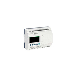
modular smart relay Zelio Logic - 26 I O - 100..240 V AC - clock - display
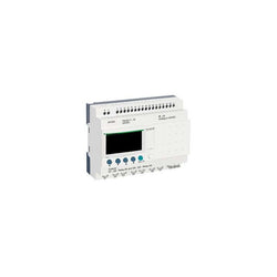
modular smart relay Zelio Logic - 26 I O - 24 V DC - clock - display
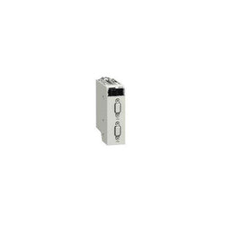
backplane expander M340 - for multiracks configuration

Main
| Characteristic | Value(s) |
|---|---|
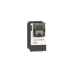
| Range of Product | Altivar 71 |
| Product or Component Type | Variable speed drive |
| Product Specific Application | Complex, high-power machines |
| Component name | ATV71 |
| Motor power kW | 45 kW, 3 phase 380...480 V |
| Maximum Horse Power Rating | 60 hp, 3 phase 380...480 V |
| Maximum motor cable length | 328.08 ft (100 m) shielded cable 656.2 ft (200 m) unshielded cable |
| power supply voltage | 380...480 V - 15...10 % |
| Phase | 3 phase |
| Line current | 104 A 380 V 3 phase 45 kW / 60 hp 85 A 480 V 3 phase 45 kW / 60 hp |
| EMC filter | Integrated |
| Assembly style | With heat sink |
| Apparent power | 68.5 kVA 380 V 3 phase 45 kW / 60 hp |
| Prospective line Isc | 22 kA 3 phase |
| Nominal output current | 77 A 2.5 kHz 460 V 3 phase 45 kW / 60 hp 94 A 2.5 kHz 380 V 3 phase 45 kW / 60 hp |
| Maximum transient current | 141 A 60 s 3 phase 45 kW / 60 hp 155 A 2 s 3 phase 45 kW / 60 hp |
| Output frequency | 0.1â¦500 Hz |
| Nominal switching frequency | 2.5 kHz |
| Switching frequency | 1...16 kHz adjustable 2.5...16 kHz with derating factor |
| Asynchronous motor control profile | Flux vector control (FVC) with sensor (current vector) Voltage/frequency ratio (2 or 5 points) ENA (Energy adaptation) system for unbalanced loads Sensorless flux vector control (SFVC) (voltage or current vector) |
| Type of polarization | No impedance Modbus |
Complementary
| Characteristic | Value(s) |
|---|---|
| Product destination | Synchronous motors Asynchronous motors |
| power supply voltage limits | 323â¦528 V |
| power supply frequency | 50...60 Hz - 5...5 % |
| power supply frequency limits | 47.5...63 Hz |
| Speed range | 1â¦100 asynchronous motor in open-loop mode, without speed feedback 1â¦1000 asynchronous motor in closed-loop mode with encoder feedback 1â¦50 synchronous motor in open-loop mode, without speed feedback |
| Speed accuracy | +/- 0.01 % of nominal speed in closed-loop mode with encoder feedback 0.2 Tn to Tn +/- 10 % of nominal slip without speed feedback 0.2 Tn to Tn |
| Torque accuracy | +/- 15 % in open-loop mode, without speed feedback +/- 5 % in closed-loop mode with encoder feedback |
| Transient overtorque | 170 % +/- 10 % 60 s every 10 minutes 220 % +/- 10 % 2 s |
| Braking torque | <= 150 % with braking or hoist resistor 30 % without braking resistor |
| Synchronous motor control profile | Vector control without speed feedback |
| Regulation loop | Adjustable PI regulator |
| Motor slip compensation | Automatic whatever the load Not available in voltage/frequency ratio (2 or 5 points) Suppressable Adjustable |
| diagnostic | 1 LED (red) for drive voltage |
| Output voltage | <= power supply voltage |
| Insulation | Electrical between power and control |
| type of cable for mounting in an enclosure | With a NEMA Type1 kit 3 UL 508 cable 104 °F (40 °C), copper 75 °C / PVC With an IP21 or an IP31 kit 3 IEC cable 104 °F (40 °C), copper 70 °C / PVC Without mounting kit 1 IEC cable 113 °F (45 °C), copper 70 °C / PVC Without mounting kit 1 IEC cable 113 °F (45 °C), copper 90 °C / XLPE/EPR |
| Electrical connection | Terminal 2.5 mm², AWG 14 AI1-/AI1+, AI2, AO1, R1A, R1B, R1C, R2A, R2B, LI1...LI6, PWR) Terminal 150 mm² L1/R, L2/S, L3/T, U/T1, V/T2, W/T3, PC/-, PO, PA/+, PA, PB) |
| Tightening torque | 5.3 lbf.in (0.6 N.m) AI1-/AI1+, AI2, AO1, R1A, R1B, R1C, R2A, R2B, LI1...LI6, PWR) 362.9 lbf.in (41 N.m), 360 lb.in L1/R, L2/S, L3/T, U/T1, V/T2, W/T3, PC/-, PO, PA/+, PA, PB) |
| Supply | Internal supply for reference potentiometer (1 to 10 kOhm) 10.5 V DC +/- 5 %, <10 mA overload and short-circuit protection Internal supply 24 V DC 21â¦27 V), <200 mA overload and short-circuit protection |
| Analogue input number | 2 |
| Analogue input type | AI1-/Al1+ bipolar differential voltage +/- 10 V DC 24 V max 11 bits + sign AI2 software-configurable current 0...20 mA 242 Ohm 11 bits AI2 software-configurable voltage 0...10 V DC 24 V max 30000 Ohm 11 bits |
| input sampling time | 2 ms +/- 0.5 ms AI1-/Al1+) - analog 2 ms +/- 0.5 ms Al2) - analog 2 ms +/- 0.5 ms LI1...LI5) - discrete 2 ms +/- 0.5 ms LI6)if configured as logic input - discrete |
| Response time | <= 100 ms in STO (Safe Torque Off) AO1 2 ms +/- 0.5 ms analog R1A, R1B, R1C 7 ms +/- 0.5 ms discrete R2A, R2B 7 ms +/- 0.5 ms discrete |
| absolute accuracy precision | +/- 0.6 % AI1-/Al1+) for a temperature variation 60 °C +/- 0.6 % AI2) for a temperature variation 60 °C +/- 1 % AO1) for a temperature variation 60 °C |
| Linearity error | +/- 0.15 % of maximum value AI1-/Al1+, AI2) +/- 0.2 % AO1) |
| Analogue output number | 1 |
| Analogue output type | AO1 software-configurable logic output 10 V 20 mA AO1 software-configurable current 0...20 mA 500 Ohm 10 bits AO1 software-configurable voltage 0...10 V DC 470 Ohm 10 bits |
| Discrete output number | 2 |
| Discrete output type | Configurable relay logic R1A, R1B, R1C) NO/NC - 100000 cycles Configurable relay logic R2A, R2B) NO - 100000 cycles |
| Minimum switching current | 3 mA 24 V DC configurable relay logic |
| Maximum switching current | R1, R2 2 A 250 V AC inductive, cos phi = 0.4 R1, R2 2 A 30 V DC inductive, cos phi = 0.4 R1, R2 5 A 250 V AC resistive, cos phi = 1 R1, R2 5 A 30 V DC resistive, cos phi = 1 |
| Discrete input number | 7 |
| Discrete input type | LI1...LI5 programmable 24 V DC level 1 PLC 3500 Ohm LI6 switch-configurable 24 V DC level 1 PLC 3500 Ohm LI6 switch-configurable PTC probe 0â¦6 1500 Ohm PWR safety input 24 V DC 1500 Ohm ISO 13849-1 level d |
| Discrete input logic | Negative logic (sink) LI1...LI5), > 16 V, < 10 V Positive logic (source) LI1...LI5), < 5 V, > 11 V Negative logic (sink) LI6)if configured as logic input, > 16 V, < 10 V Positive logic (source) LI6)if configured as logic input, < 5 V, > 11 V |
| Acceleration and deceleration ramps | S, U or customized Linear adjustable separately from 0.01 to 9000 s Automatic adaptation of ramp if braking capacity exceeded, by using resistor |
| Braking to standstill | By DC injection |
| Protection type | Against exceeding limit speed drive Against input phase loss drive Break on the control circuit drive Input phase breaks drive Line supply overvoltage drive Line supply undervoltage drive Overcurrent between output phases and earth drive Overheating protection drive Overvoltages on the DC bus drive Short-circuit between motor phases drive Thermal protection drive Motor phase break motor Power removal motor Thermal protection motor |
| Insulation resistance | > 1 mOhm 500 V DC for 1 minute to earth |
| Frequency resolution | Analog input 0.024/50 Hz Display unit 0.1 Hz |
| Communication Port Protocol | Modbus CANopen |
| Connector type | 1 RJ45 on front face)Modbus 1 RJ45 on terminal)Modbus Male SUB-D 9 on RJ45CANopen |
| Physical interface | 2-wire RS 485 Modbus |
| Transmission frame | RTU Modbus |
| Transmission rate | 4800 bps, 9600 bps, 19200 bps, 38.4 Kbps Modbus on terminal 9600 bps, 19200 bps Modbus on front face 20 kbps, 50 kbps, 125 kbps, 250 kbps, 500 kbps, 1 Mbps CANopen |
| Data format | 8 bits, 1 stop, even parity Modbus on front face 8 bits, odd even or no configurable parity Modbus on terminal |
| Number of addresses | 1â¦127 CANopen 1â¦247 Modbus |
| Method of access | Slave CANopen |
| Marking | CE |
| Operating position | Vertical +/- 10 degree |
| Height | 24.8 in (630 mm) |
| Depth | 11.4 in (290 mm) |
| Width | 12.6 in (320 mm) |
| Product Weight | 97.003 lb(US) (44 kg) |
| Functionality | Full |
| Specific application | Other applications |
| Option card | Communication card CC-Link Controller inside programmable card Communication card DeviceNet Communication card EtherNet/IP Communication card Fipio I/O extension card Communication card Interbus-S Interface card for encoder Communication card Modbus Plus Communication card Modbus TCP Communication card Modbus/Uni-Telway Overhead crane card Communication card Profibus DP Communication card Profibus DP V1 |

This analog mixed I/O module is part of the Modicon X80 modules. It has 4 non-isolated inputs (14/12 bits) and 2 non-isolated outputs (12 bits). It offers different ranges of voltage or current for each of the inputs / outputs depending on configuration choice. It occupies a single slot on the rack and it has a case which provides IP 20 protection of the electronics.
Main
| Characteristic | Value(s) |
|---|---|
| Range of Product | Modicon X80 |
| Product or Component Type | Mixed analog I/O module |
| Electrical connection | 20 ways 1 connector |
| Isolation between channels | Non isolated |
| Input level | High level |
| Analogue input number | 4 |
| Analogue input type | Current 0...20 mA Current 4...20 mA Voltage +/- 10 V Voltage 0...10 V Voltage 0...5 V Voltage 1...5 V |
Complementary
| Characteristic | Value(s) |
|---|---|
| Analogue input resolution | 12 bits 0...20 mA 12 bits 0...5 V 12 bits 1...5 V 12 bits 4...20 mA 13 bits 0...10 V 14 bits +/- 10 V |
| Permitted overload on inputs | +/- 30 mA 0...20 mA +/- 30 mA 4...20 mA +/- 30 V +/- 10 V +/- 30 V 0...10 V +/- 30 V 0...5 V +/- 30 V 1...5 V |
| Input impedance | 250 Ohm |
| Precision of internal conversion resistor | 0.1 % - 15 ppm/°C |
| Type of filter | First order digital filtering by firmware |
| Fast read cycle time | 1 ms + 1 ms x number of channels used |
| Nominal read cycle time | 5 ms for 4 channels |
| Measurement error | 0.25 % of full scale 0...20 mA 25 °C output 0.25 % of full scale 4...20 mA 25 °C output <= 0.35 % of full scale +/- 10 V 0...60 °C input <= 0.35 % of full scale 0...10 V 0...60 °C input <= 0.35 % of full scale 0...5 V 0...60 °C input <= 0.35 % of full scale 1...5 V 0...60 °C input <= 0.5 % of full scale 0...20 mA 0...60 °C input <= 0.5 % of full scale 4...20 mA 0...60 °C input <= 0.6 % of full scale +/- 10 V 0...60 °C output <= 0.6 % of full scale 0...20 mA 0...60 °C output <= 0.6 % of full scale 4...20 mA 0...60 °C output 0.25 % of full scale +/- 10 V 25 °C output 0.25 % of full scale +/- 10 V 25 °C input 0.25 % of full scale 0...10 V 25 °C input 0.25 % of full scale 0...5 V 25 °C input 0.25 % of full scale 1...5 V 25 °C input 0.35 % of full scale 0...20 mA 25 °C input 0.35 % of full scale 4...20 mA 25 °C |
| Temperature drift | 100 ppm/°C +/- 10 V output 100 ppm/°C 0...20 mA output 100 ppm/°C 4...20 mA output 30 ppm/°C +/- 10 V input 30 ppm/°C 0...10 V input 30 ppm/°C 0...5 V input 30 ppm/°C 1...5 V input 50 ppm/°C 0...20 mA input 50 ppm/°C 4...20 mA input |
| Recalibration | Factory calibrated on outputs Internal on inputs |
| Minimum crosstalk attenuation | 70 dB |
| EMI/RFI Noise rejection (100 kHz to 10 MHz) | 80 dB |
| Isolation voltage | 1400 V DC between channels and ground 1400 V DC between channels and bus 750 V DC between group of I/O channels |
| Output level | High level |
| Analogue output number | 2 |
| Analogue output type | Current 0...20 mA Current 4...20 mA Voltage +/- 10 V |
| Analogue output resolution | 11 bits, 0...20 mA 11 bits, 4...20 mA 12 bits, +/- 10 V |
| Conversion time | <= 2 ms |
| Maximum conversion value | +/- 11.25 V +/- 10 V output +/- 11.25 V +/- 10 V input 0...30 mA 0...20 mA input 0...30 mA 4...20 mA input +/- 11.25 V 0...10 V input +/- 11.25 V 0...5 V input +/- 11.25 V 1...5 V input 0...24 mA 0...20 mA output 0...24 mA 4...20 mA output |
| Fallback mode | Predefined Configurable |
| MTBF reliability | 1400000 H |
| Operating altitude | 0...6561.68 ft (0...2000 m) 2000...5000 m with derating factor |
| Status LED | 1 LED (Green) RUN 1 LED per channel (Green) channel diagnostic 1 LED (Red) ERR 1 LED (Red) I/O |
| Product Weight | 0.342 lb(US) (0.155 kg) |
| Power consumption in W | 2.6 W 24 V DC typical 3.2 W 24 V DC maximum 0.35 W 3.3 V DC typical 0.48 W 3.3 V DC maximum |
| Current consumption | 240 mA 3.3 V DC |

Variable Speed Drive - ATV930 - 1,5kW - 400/480V - with braking unit - IP21
Variable Speed Drive Altivar 71 - 0.75kW-1hp - 480V - with EMC filter and Graphic Terminal
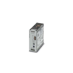
Primary-switched QUINT POWER power supply with free choice of output characteristic curve, SFB�(selective fuse breaking) technology, and NFC interface, input: 3-phase,�output:�24�V�DC/10 A
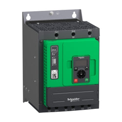
Altivar Soft Starter Ats480 Is Intended To Start And Stop Asynchronous Motors Supplied From 208V To 690V. It Meets The Requirements Of The Most Demanding Applications In Normal And Heavy Duty. With An Operational Rated Current Of 110A In Normal Duty, It Supplies Motor From 30Kw To 90Kw According To Mains Voltage. Designed For Digitization, Connected, Optimized To Meet Cybersecurity Standard, It Simplifies Project Execution And Maximizes The Availability Of Applications. Its Torque Control (Tcs) Masters Acceleration And Deceleration. It Efficiently Stops High Inertia Application Thanks To The Dynamic Braking And Dc Injection. It Could Be Connected In-Line Or Inside The Delta To Reduce Its Operational Current. The Embedded Test Routine Simplifies The Commissioning Inside The Delta. Its Dimensions Are 190Mm (Width) X 247Mm (Depth) X 290Mm (Height) And It Weighs 8,3Kg. Altivar Soft Starter Ats480 Is Designed To Address Process, Infrastructures And Industrial Machines. It Conforms To Iec/En60947-4-1. It Is Certified Ce, Culus, Ukca, Ccc, Rcm, Eac, And Marine Certified Dnv, Abs, Bv And Ccs. Display Terminals, Remote Mounting Kit, Communication Modules Are Common With Altivar Drives. Line Chokes, Dnv Kits Are Common With Ats48. Ats480 Is Compatible With Ats48, It Has Same Footprint, Fixing, Torque Control Algorithm, I/O, Menus… The Integration Of Altivar Soft Starter Ats480 In Ecostruxure Drastically Simplifies Architecture Selection, Detailed Design And Execution In Automation And Electrical Systems. It Is A Green Premium Product Designed To Take The Environmental Considerations Beyond Current Directives And Regulations, Compliant With Rohs And Reach. Test1

Altivar Soft Starter ATS480 is intended to start and stop asynchronous motors supplied from 208V to 690V. It meets the requirements of the most demanding applications in normal and heavy duty. With an operational rated current of 88A in normal duty, it supplies motor from 22kW to 75kW according to mains voltage. Designed for digitization, connected, optimized to meet cybersecurity standard, it simplifies project execution and maximizes the availability of applications. Its torque control (TCS) masters acceleration and deceleration. It efficiently stops high inertia application thanks to the dynamic braking and DC injection. It could be connected in-line or inside the delta to reduce its operational current. The embedded test routine simplifies the commissioning inside the delta. Its dimensions are 190mm (width) x 247mm (depth) x 290mm (height) and it weighs 8,3kg. Altivar Soft Starter ATS480 is designed to address process, infrastructures and industrial machines. It conforms to IEC/EN60947-4-1. It is certified CE, cULus, UKCA, CCC, RCM, EAC, and Marine certified DNV, ABS, BV and CCS. Display terminals, remote mounting kit, communication modules are common with Altivar Drives. Line chokes, DNV kits are common with ATS48. ATS480 is compatible with ATS48, it has same footprint, fixing, torque control algorithm, I/O, menus⦠The integration of Altivar Soft Starter ATS480 in EcoStruxure drastically simplifies architecture selection, detailed design and execution in automation and electrical systems.
Main
| Characteristic | Value(s) |
|---|---|
| Range of Product | Altivar Soft Starter ATS480 |
| Product or Component Type | Soft starter |
| Product destination | Asynchronous motors |
| Product Specific Application | Process and infrastructures |
| Device short name | ATS480 |
| Phase | 3 phase |
| Utilisation category | AC-3A AC-53A |
| Ue power supply voltage | 208...690 V - 15...10 % |
| power supply frequency | 50...60 Hz - 20...20 % |
| [Ie] rated operational current | Normal duty 88.0 A 104 °F (40 °C)) |
| rated current in heavy duty | 75.0 A at 104 °F (40 °C) heavy duty |
| Torque control | True |
| IP Degree of Protection | IP20 |
| Motor power kW | 22.0 kW 230 V in the motor supply line normal duty 18.5 kW 230 V in the motor supply line heavy duty 45.0 kW 400 V in the motor supply line normal duty 37.0 kW 400 V in the motor supply line heavy duty 45.0 kW 440 V in the motor supply line normal duty 37.0 kW 440 V in the motor supply line heavy duty 55.0 kW 500 V in the motor supply line normal duty 45.0 kW 500 V in the motor supply line heavy duty 55.0 kW 525 V in the motor supply line normal duty 45.0 kW 525 V in the motor supply line heavy duty 75.0 kW 660 V in the motor supply line normal duty 55.0 kW 660 V in the motor supply line heavy duty 75.0 kW 690 V in the motor supply line normal duty 55.0 kW 690 V in the motor supply line heavy duty 45.0 kW 230 V to the motor delta terminals normal duty 37.0 kW 230 V to the motor delta terminals heavy duty 75.0 kW 400 V to the motor delta terminals normal duty 55.0 kW 400 V to the motor delta terminals heavy duty |
| Maximum Horse Power Rating | 25.0 hp 208 V normal duty 20.0 hp 208 V heavy duty 30.0 hp 230 V normal duty 25.0 hp 230 V heavy duty 60.0 hp 460 V normal duty 50.0 hp 460 V heavy duty 75.0 hp 575 V normal duty 60.0 hp 575 V heavy duty |
| Option card | Communication module Profibus DP V1 Communication module Modbus TCP/EtherNet/IP Communication module CANopen daisy chain Communication module CANopen Sub-D Communication module CANopen open style Communication module PROFINET |
Complementary
| Characteristic | Value(s) |
|---|---|
| Device connection | In the motor supply line To the motor delta terminals |
| [Us] control circuit voltage | 110...230 V AC 50/60 Hz - 15...10 % |
| Apparent power | 0.09 kVA |
| Integrated motor overload protection | True |
| motor thermal protection class | Class 10E |
| Protection type | Phase failure line Integrated thermal protection motor Thermal protection starter Current overload motor Underload motor Excessive starting time, locked rotor motor Motor phase loss motor Line supply phase loss line Line supply phase loss motor Thermal protection motor |
| current limiting %In (5 x Ie maximum) | 150â¦700 % |
| [In] Rated current pwr loss specifctn | 88.0 A |
| Power loss static current independent | 25.0 W |
| Power loss per device current dependent | 270.0 W |
| Standards | IEC 60947-4-2 UL 60947-4-2 IEC 60664-1 |
| Product Certifications | CE cULus CCC UKCA RCM EAC DNV ABS BV CCS |
| Marking | CE CCC UKCA EAC RCM CULus |
| [Uc] control circuit voltage | 24 V DC |
| Discrete input number | 4 |
| Discrete input type | STOP) logic inputs, 3500 Ohm RUN) logic inputs, 3500 Ohm DI3) programmable as logic input, 3500 Ohm DI4) programmable as logic input, 3500 Ohm |
| Input compatibility | STOP discrete input level 1 PLC IEC 61131-2 RUN discrete input level 1 PLC IEC 61131-2 DI3 discrete input level 1 PLC IEC 61131-2 DI4 discrete input level 1 PLC IEC 61131-2 |
| Discrete input logic | Programmable digital input < 5 V |
| Relay output number | 3 |
| Relay output type | Relay outputs R1A 1 NO Relay outputs R1B 1 NO Relay outputs RIC NO/NC programmable |
| Minimum switching current | 100 mA 12 V DC relay outputs |
| Maximum switching current | Relay outputs 2 A 250 V AC Relay outputs 2 A 30 V DC Relay outputs |
| Discrete output number | 2 |
| Discrete output type | DQ1) programmable digital output <= 30 V DQ2) programmable digital output <= 30 V |
| Output compatibility | Open collector level 1 PLC IEC 65A-68 |
| Analogue input number | 1 |
| Analogue input type | AI1/PTC PTC/Pt 100 temperature probe PTC2 PTC/Pt 100 temperature probe PTC3 PTC/Pt 100 temperature probe |
| Analogue output number | 1 |
| Analogue output type | Current output AQ1 0...20 mA or 0...10 V 500 Ohm |
| Communication Port Protocol | Modbus serial |
| Connector Type | 1 RJ45 |
| Communication data link | Serial |
| Physical interface | 2-wire RS 485 |
| Transmission Rate | 1200...256000 bit/s |
| Transmission frame | RTU |
| Data format | 8 bits, configurable odd, even or no parity |
| Type of polarization | No impedance Modbus serial |
| Number of addresses | 0â¦227 Modbus serial |
| Method of access | Slave Modbus serial |
| Function Available | External bypass control Pre-heating Smoke extraction Multi-motor cascade Second motor set User management Ports and services hardening Security event logging Cybersecure firmware update Single direction |
| Display screen available | True |
| Operating position | Vertical +/- 10 degree |
| Height | 11.4 in (290.0 mm) |
| Width | 7.5 in (190.0 mm) |
| Depth | 9.7 in (247.0 mm) |
| Product Weight | 18.3 lb(US) (8.3 kg) |

This Lexium 32 Servo Drive Works At A Rated Supply Voltage From 208V Ac To 480V Ac. It Can Feed 3-Phase Synchronous Motors Bmh Or Bsh, Its Continuous Output Current Is 10A At 8Khz. The Compact Size Of The Servo Drive And Associated Servo Motor Provides Maximum Power In The Minimum Space. This Servo Drive Is Specifically Designed For Industrial Machines. It Offers High Performance, Power And Simplicity Of Use In Motion Control Applications. It Complies With International Standards Iec/En 61800-5-1, Iec/En 61800-3, And Is Ul And Csa And Is Ul And Csa Certified And Ce Marked. It Has Been Developed To Meet The Requirements Of Directives Regarding Protection Of The Environment (Rohs).

Safety relay (standalone), inputs: 1/2-channel wiring with/without detection of shorts across contacts, outputs: 3 N/O, 1 N/C,1 SC, automatic/monitored start, UB 24 V AC/DC, width: 45 mm, screw terminals integrated, monitoring of E-STOP, safety gates.

Configurable safe small controllers PNOZmulti 2, expansion module, 8 safe digital inputs, 4 safe semiconductor outputs.

PNOZsigma contact expansion, outputs: 4 N/O, 1 N/C, UB 24 V DC, width: 17.5 mm, plug-in spring-loaded terminals, contact block for contact expansion in connection with safety-related control components.

PNOZsigma safety relay (standalone), inputs: 1/2-channel wiring with/without detection of shorts across contacts, manual/automatic start, outputs: 3 N/O, 1 N/C, 1 SC, UB 24 V DC, width: 22.5 mm, plug-in spring-loaded terminals, monitoring of E-STOP, safety gates, lightguard.