
 1 year warranty

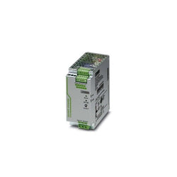
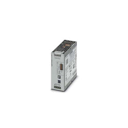
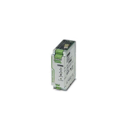
Primary-switched QUINT POWER power supply for DIN rail mounting with SFB (Selective Fuse Breaking) Technology, input: 1-phase, output: 48 V DC/5 A
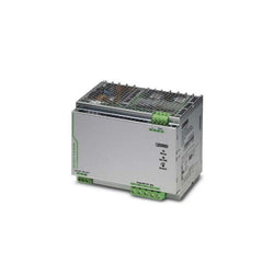
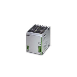
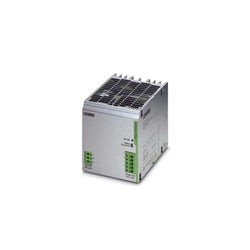
Primary-switched QUINT POWER power supply for DIN rail mounting with SFB (Selective Fuse Breaking) Technology, input: 1-phase, output: 48 V DC/20 A

Primary-switched QUINT POWER power supply for DIN rail mounting with SFB (Selective Fuse Breaking) Technology, input: 1-phase, output: 12 V DC/20 A

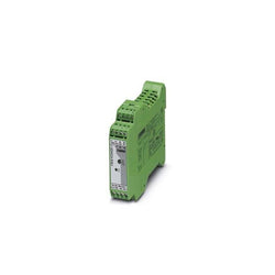
Isolating amplifier with safe electrical isolation and wide-range power supply (24 V ... 230 V AC/DC). DIP switches on the front, over 1600 signal conversions can be set. Standard configuration (IN 0 ... 10 V/OUT 0 ... 20 mA), screw connection, SIL.

Ex i repeater power supply and input signal conditioner, HART. Transmits supplied or active 0/4 - 20 mA signals from the hazardous area to a load (active or passive) in the safe area. 3-way electrical isolation SIL 2 according to IEC 61508, with screw connection
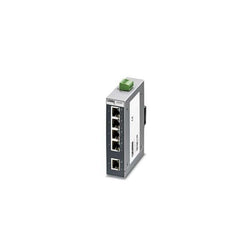
Ethernet switch, 5 TP RJ45 ports, automatic detection of data transmission speed of 10 or 100 Mbps (RJ45), autocrossing function
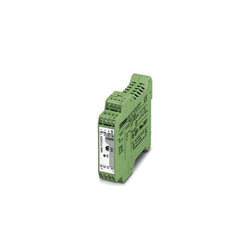
DIN rail power supply unit 24 V DC/1 A, primary-switched mode, slim design
Primary-switched QUINT POWER power supply with free choice of output characteristic curve, SFB�(selective fuse breaking) technology, and NFC interface, input: 3-phase,�output:�24�V�DC/10 A
Primary-switched TRIO POWER power supply with push-in connection for DIN rail mounting, input: 3-phase, output: 24�V�DC/20�A

Uninterruptible power supply with integrated power supply unit, 4 A, in combination with MINI-BAT/12/DC 1.6 Ah or 2.6 Ah
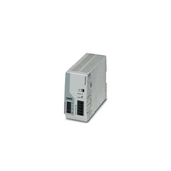
Primary-switched TRIO POWER power supply for DIN rail mounting, input: 1-phase, output: 48 V DC/10 A
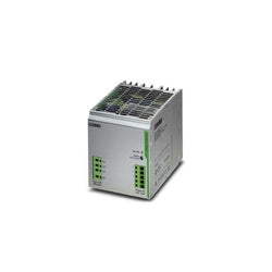
Primary-switched TRIO POWER power supply for DIN rail mounting, input: 3-phase, output: 24 V DC/20 A
Primary-switched TRIO POWER power supply for DIN rail mounting, input: 1-phase, output: 24 V DC/20 A
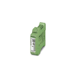
Primary-switched MINI DC/DC converter for DIN rail mounting, input: 1-phase, output: 24 V DC/1 A
QUINT-PS/24DC/24DC/10 Primary-switched QUINT DC/DC converter for DIN rail mounting with SFB (Selective Fuse Breaking) Technology, input: 24 V DC, output: 24 V DC/10 A
Primary-switched MINI DC/DC converter for DIN rail mounting, input: 1-phase, output: 5 - 15 V DC/2 A

Omron Retroreflective Photoelectric Sensor, Rectangular Sensor, 4000 mm Detection Range

"4 in 1" three-phase semiconductor reversing contactor with 24 V DC input, 9 A output current, emergency stop function, and adjustable overload switching.
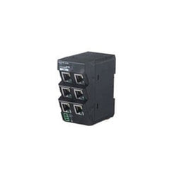
Ethernet Modules SPECIAL SEMICONDUCTOR JS

Safety relay unit, 24VDC, 4 safety outputs 5A max, aux. output
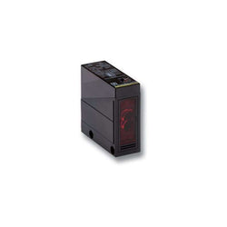
Photoelectric sensor retro-reflective 4m AC/DC relay timer 5s

G-Series Servo Drive Pulse input type 800 W 1~ 200 VAC
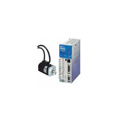
SERVO DRIVE, 750 W, PULSE INPUT, 240 VAC, SINGLE PHASE

NX I/O power feed unit, 5-24 V DC input, 8 terminals, 4A, screwless push-in connector, 12mm wide