
 1 year warranty


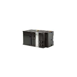
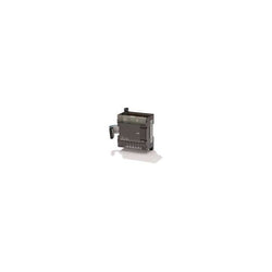
EtherCAT Coupler Unit, 46 MM x 71 MM x 100 MM, 5 to 24 VDC, 4 A, 1.45 W, 63-Input, EtherCAT Coupler Unit for Automation Control System Networking Distributed Input/Output.
Controllers NX 1Pt Inc Enc 5V PNP

Controllers H&held NS5 w/Re estop 60M

DIN Rail Power Supplies Sysmac NJ Power Supply DC
Rack Mount Power Supplies Sysmac NJ Power Supply AC
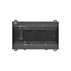
CP2E series compact PLC - Network type; 24 DI, 16 DO; PNP output; Power supply 24 VDC; 10 kStep Program memory
DeviceNet Module, functions as either a master or a slave, 2,048 I/O points, multi-drop & T-branch connections, Baud rate: 500 Kbps, 250 Kbps, or 125 Kbps, 64 nodes max, 24/DC
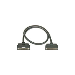
I/O expansion rack connecting cable for NJ/CJ/CS-series, 70 cm
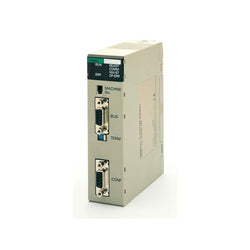
CONTROLLER LINK UNIT, FIBRE OPTIC CABLE, OPTICAL RING OR BUS, H-PCF CABLE
I/O expansion unit, 4 x RTD inputs Pt100
Expansion I/O Module, RS-422A/485 option board, 50 m max transmission, terminal block (using ferrules) connector

I/O expansion unit, 4 x analog inputs 1 to 5 V, 0 to 5 V, 0 to 10 V, -10 to 10 V, 0 to 20 mA, 4 to 20 mA, resolution 1:6000

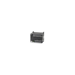
PLC, 100-240 VAC supply, 36 x 24 VDC inputs, 24 x relay outputs 2 A, 10K steps program + 32K words data memory

PLC, 100-240 VAC supply, 24 x 24 VDC inputs, 16 x relay outputs 2 A, 10K steps program + 32K words data memory

PLC, 100-240 VAC supply, 12 x 24 VDC inputs, 8 x relay outputs 2 A, 5K steps program + 10K words data memory

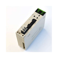
CPU, 5K steps program, 32K words data memory, 32K words x 1 bank EM, 2560 I/O max, RS-232C serial port, USB programming port, 3 expansion racks max
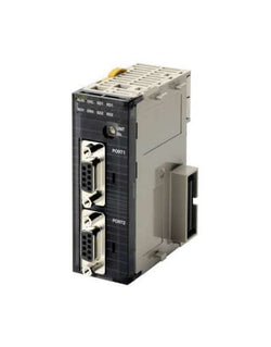
Serial communication unit, 2x RS422/485 ports, Protocol Macro, Host Link, 1:N NT Link, No protocol, Serial Gateway (CompoWay/F, Modbus-RTU, Modbus-ASCII, Host Link), Modbus RTU Slave
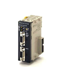
Serial high-speed communication unit, 2x RS-232C ports, Protocol Macro, Host Link, 1:N NT Link, No protocol, Serial Gateway (CompoWay/F, MODBUS-RTU, MODBUS-ASCII, Host Link), MODBUS RTU Slave, up to 230 kbps

Switching Power Supplies 24VDC Pwr Spl No RUN Output 5V-5A 24V-.8A
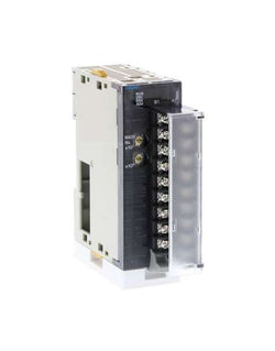
Analog output unit, 8 x outputs 4 to 20 mA, resolution 12 bit, screw terminal
COMMUNICATIONS INTERFACE MODULE, PROFIBUS DP MASTER,ALPHA,CS1,CONTROLLERS, C50084VSW

PLC, FX2N Analog output module; 12 bit; 2 analog outputs

Inverter AC; Pn: 18,5-30kW; 3x380-500V;In max: 62A;(22kW; 44A); IP20

DC digital output module - Mitsubishi Electric (MELSEC iQ-R Series) - 16I/O [16DO (16 x digital outputs (12Vdc-24Vdc; Source; 1ms response))] - with screw-clamp term. connections - Backplane / rack mounting