
 1 year warranty


TeSys D contactor - 3P(3 NO) - AC-3 - <= 440 V 65 A - 127 V AC 50/60 Hz coil
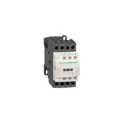
TeSys Deca contactor, 4 poles (2NO+2NC), for non-inductive load applications up to 25A/690V AC-1. They can be used to create motor starters for almost any type of application. It provides a 48V DC coil with transient suppressor module, 1NO+1NC built-in auxiliary contacts (NC mirror certified), connection by screw clamp terminals. For operating rates until 3600 cycles/hour and environments until 60°C, it procures high reliability and durability. Compact (45mm width), DIN-rail mounting or screw fixing. Power contacts have a 25A resistive load rating. Multi standards certified (IEC, UL, CSA, CCC, EAC, Marine). Contactor has one normally open and one normally closed auxiliary contact built-in as standard. The NC contact is mirror certified. Screw clamp terminals are used for load and auxiliary connections. An extensive line of accessories makes it easy to meet the requirements of most applications. The contactor is 3.35 inches tall, 1.77 inches wide and 3.90 inches deep. It weighs 1.16 lbs. Contactor is certified to UL, CSA, IEC, CCC, EAC and Marine standards.
Main
| Characteristic | Value(s) |
|---|---|
| Range of Product | TeSys Deca |
| Product or Component Type | Contactor |
| Device short name | LC1D |
| Contactor application | Resistive load |
| Utilisation category | AC-1 |
| Poles description | 4P |
| [Ue] rated operational voltage | Power circuit <= 690 V AC 25...400 Hz Power circuit <= 300 V DC |
| [Ie] rated operational current | 25 A (at <140 °F (60 °C)) at <= 440 V AC AC-1 for power circuit |
| [Uc] control circuit voltage | 48 V DC |
Complementary
| Characteristic | Value(s) |
|---|---|
| Compatibility code | LC1D |
| Pole contact composition | 2 NO + 2 NC |
| Protective cover | With |
| [Ith] conventional free air thermal current | 25 A (at 140 °F (60 °C)) for power circuit 10 A (at 140 °F (60 °C)) for signalling circuit |
| Irms rated making capacity | 250 A at 440 V for power circuit conforming to IEC 60947 140 A AC for signalling circuit conforming to IEC 60947-5-1 250 A DC for signalling circuit conforming to IEC 60947-5-1 |
| Rated breaking capacity | 250 A at 440 V for power circuit conforming to IEC 60947 |
| [Icw] rated short-time withstand current | 105 A 104 °F (40 °C) - 10 s for power circuit 210 A 104 °F (40 °C) - 1 s for power circuit 30 A 104 °F (40 °C) - 10 min for power circuit 61 A 104 °F (40 °C) - 1 min for power circuit 100 A - 1 s for signalling circuit 120 A - 500 ms for signalling circuit 140 A - 100 ms for signalling circuit |
| Associated fuse rating | 10 A gG for signalling circuit conforming to IEC 60947-5-1 40 A gG at <= 690 V coordination type 1 for power circuit 25 A gG at <= 690 V coordination type 2 for power circuit |
| Average impedance | 2.5 mOhm - Ith 25 A 50 Hz for power circuit |
| Power dissipation per pole | 1.56 W AC-1 |
| [Ui] rated insulation voltage | Power circuit 690 V IEC 60947-4-1 Power circuit 600 V CSA Power circuit 600 V UL Signalling circuit 690 V IEC 60947-1 Signalling circuit 600 V CSA Signalling circuit 600 V UL |
| Overvoltage category | III |
| pollution degree | 3 |
| [Uimp] rated impulse withstand voltage | 6 kV IEC 60947 |
| Safety reliability level | B10d = 1369863 cycles contactor with nominal load EN/ISO 13849-1 B10d = 20000000 cycles contactor with mechanical load EN/ISO 13849-1 |
| Mechanical durability | 30 Mcycles |
| Electrical durability | 0.8 Mcycles 25 A AC-1 <= 440 V |
| Control circuit type | DC standard |
| Coil technology | With integral suppression device |
| Control circuit voltage limits | 0.1...0.25 Uc (-40â¦158 °F (-40â¦70 °C)):drop-out DC 0.7...1.25 Uc (-40â¦140 °F (-40â¦60 °C)):operational DC 1...1.25 Uc (140â¦158 °F (60â¦70 °C)):operational DC |
| Inrush power in W | 5.4 W 68 °F (20 °C)) |
| Hold-in power consumption in W | 5.4 W 68 °F (20 °C) |
| Operating time | 63 ±15 % ms closing 20 ±20 % ms opening |
| Time constant | 28 ms |
| Maximum operating rate | 3600 cyc/h at 60 °C |
| Connections - terminals | Power circuit: screw clamp terminals 1 0.002â¦0.006 in² (1â¦4 mm²) - cable stiffness: flexible without cable end Power circuit: screw clamp terminals 2 0.002â¦0.006 in² (1â¦4 mm²) - cable stiffness: flexible without cable end Power circuit: screw clamp terminals 1 0.002â¦0.006 in² (1â¦4 mm²) - cable stiffness: flexible with cable end Power circuit: screw clamp terminals 2 0.002â¦0.004 in² (1â¦2.5 mm²) - cable stiffness: flexible with cable end Power circuit: screw clamp terminals 1 0.002â¦0.006 in² (1â¦4 mm²) - cable stiffness: solid without cable end Power circuit: screw clamp terminals 2 0.002â¦0.006 in² (1â¦4 mm²) - cable stiffness: solid without cable end Control circuit: screw clamp terminals 1 0.002â¦0.006 in² (1â¦4 mm²) - cable stiffness: flexible without cable end Control circuit: screw clamp terminals 2 0.002â¦0.006 in² (1â¦4 mm²) - cable stiffness: flexible without cable end Control circuit: screw clamp terminals 1 0.002â¦0.006 in² (1â¦4 mm²) - cable stiffness: flexible with cable end Control circuit: screw clamp terminals 2 0.002â¦0.004 in² (1â¦2.5 mm²) - cable stiffness: flexible with cable end Control circuit: screw clamp terminals 1 0.002â¦0.006 in² (1â¦4 mm²) - cable stiffness: solid without cable end Control circuit: screw clamp terminals 2 0.002â¦0.006 in² (1â¦4 mm²) - cable stiffness: solid without cable end |
| Tightening torque | Power circuit 15.05 lbf.in (1.7 N.m) screw clamp terminals flat à 6 mm Power circuit 15.05 lbf.in (1.7 N.m) screw clamp terminals Philips No 2 Control circuit 15.05 lbf.in (1.7 N.m) screw clamp terminals flat à 6 mm Control circuit 15.05 lbf.in (1.7 N.m) screw clamp terminals Philips No 2 Control circuit 15.05 lbf.in (1.7 N.m) screw clamp terminals pozidriv No 2 Power circuit 15.05 lbf.in (1.7 N.m) screw clamp terminals pozidriv No 2 |
| Auxiliary contact composition | 1 NO + 1 NC |
| Auxiliary contacts type | Mechanically linked 1 NO + 1 NC IEC 60947-5-1 Mirror contact 1 NC IEC 60947-4-1 |
| Signalling circuit frequency | 25...400 Hz |
| Minimum switching voltage | 17 V for signalling circuit |
| Minimum switching current | 5 mA for signalling circuit |
| Insulation resistance | > 10 MOhm for signalling circuit |
| Non-overlap time | 1.5 ms on de-energisation between NC and NO contact 1.5 ms on energisation between NC and NO contact |
| Mounting Support | Plate Rail |

TeSys SK mini-contactor, 2 poles (2NO), for non inductive load applications up to 12A/690V AC-1, and for 1-phase motor control applications up to 6A/690V AC-3 (for 3-phase motors an add-on contact block LA1SK must be mounted on contactor). It provides a 110V 50/60Hz AC control circuit, connection by screw clamp terminals. For operating rates until 1200 cycles/hour and ambient temperature -20/+50°C, it procures high reliability and durability. Compact (27mm width), for clipping on a 35mm DIN rail. Add-on contact blocks LA1SK (power pole, instantaneous auxiliary contacts) and suppressor modules LA4SK available (to be ordered separately). Multi standards certified (IEC, UL, CSA, CCC, EAC), Green Premium product (RoHS/REACh).
Main
| Characteristic | Value(s) |
|---|---|
| Range | TeSys |
| product name | TeSys SK |
| Product or Component Type | Mini contactor |
| Device short name | LC1SK |
| Contactor application | Motor control Resistive load |
| Utilisation category | AC-1 AC-3 |
| power pole contact composition | 2P |
| Pole contact composition | 2 NO |
| [Ie] rated operational current | 6 A at <= 440 V AC AC-3 12 A (at <131 °F (55 °C)) AC AC-1 |
| [Ue] rated operational voltage | Power circuit 690 V AC 50/60 Hz |
Complementary
| Characteristic | Value(s) |
|---|---|
| Control circuit type | AC 50/60 Hz |
| [Uc] control circuit voltage | 110 V AC 50/60 Hz |
| [Ith] conventional free air thermal current | 12 A (at 131 °F (55 °C)) for power circuit |
| Irms rated making capacity | 66 A at 690 V AC conforming to IEC 60947 66 A at 690 V AC conforming to NF C 63-110 |
| Rated breaking capacity | 52 A at <= 400 V for power circuit conforming to NF C 63-110 52 A at <= 400 V for power circuit conforming to IEC 60947 |
| [Icw] rated short-time withstand current | 50 A 131 °F (55 °C) for power circuit |
| Associated fuse rating | 16 A gI at <= 440 V for power circuit conforming to IEC 60947 |
| Average impedance | 4 mOhm - Ith 12 A 50 Hz |
| [Ui] rated insulation voltage | 690 V IEC 60947 690 V VDE 0110 group C 690 V BS 5424 690 V UL 508 690 V CSA C22.2 No 14 |
| Mounting Support | Rail |
| Standards | EN/IEC 60947-4-1 UL 60947-4-1 CSA C22.2 No 60947-4-1 |
| Product Certifications | CB Scheme CE UKCA EAC cULus |
| Connections - terminals | Power circuit connector 1 0.0005â¦0.009 in² (0.35â¦6 mm²)flexible with cable end Power circuit connector 1 0.0008â¦0.009 in² (0.5â¦6 mm²)flexible without cable end Power circuit connector 1 0.002â¦0.009 in² (1.5â¦6 mm²)solid Power circuit connector 2 0.0005â¦0.002 in² (0.35â¦1.5 mm²)flexible with cable end Power circuit connector 2 0.0005â¦0.004 in² (0.35â¦2.5 mm²)flexible without cable end Power circuit connector 2 0.002â¦0.006 in² (1.5â¦4 mm²)solid |
| Tightening torque | 7.08 lbf.in (0.8 N.m) connector pozidriv No 1 |
| Operating time | 6...8 ms coil de-energisation and NO opening 7...14 ms coil energisation and NO closing |
| Mechanical durability | 10 Mcycles |
| Maximum operating rate | 1200 cyc/h |
| Control circuit voltage limits | Operational: 0.85...1.1 Uc (at <122 °F (50 °C)) Drop-out: 0.2...0.75 Uc (at <122 °F (50 °C)) |
| Inrush power in VA | 16 VA (at 68 °F (20 °C)) |
| Hold-in power consumption in VA | 4.2 VA (at 68 °F (20 °C)) |
| Heat dissipation | 1.4 W 50/60 Hz |

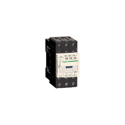
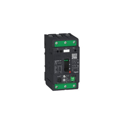
TeSys D contactor, 3 poles (3NO), for motor control applications up to 65A/690V AC-3/3e (30kW@400V). It provides a low consumption 100-250V AC/DC coil with electronic control, 1NO+1NC built-in auxiliary contacts (NC mirror certified), connection by lugs-ring terminals. For operating rates until 3600 cycles/hour and environments until 60°C, it procures high reliability and durability to demanding applications. Compact (55mm width), DIN-rail mounting or screw fixing. Multi standards certified (IEC, UL, CSA, CCC, EAC, Marine).
Main
| Characteristic | Value(s) |
|---|---|
| Range | TeSys TeSys Deca |
| Range of product | TeSys Deca |
| Product or component type | Contactor |
| Device short name | LC1D |
| Contactor application | Motor control Resistive load |
| Utilisation category | AC-1 AC-3 AC-3e |
| Poles description | 3P |
| [Ue] rated operational voltage | Power circuit: <= 690 V AC 25...400 Hz |
| [Ie] rated operational current | 80 A (at <60 °C) at <= 440 V AC-1 for power circuit 65 A (at <60 °C) at <= 440 V AC-3 for power circuit 65 A (at <60 °C) at <= 440 V AC-3e for power circuit |
| [Uc] control circuit voltage | 100...250 V AC 50/60 Hz 100...250 V DC |
Complementary
| Characteristic | Value(s) |
|---|---|
| Motor power kW | 18.5 kW at 220...230 V AC 50 Hz (AC-3) 30 kW at 380...400 V AC 50 Hz (AC-3) 37 kW at 415 V AC 50 Hz (AC-3) 37 kW at 440 V AC 50 Hz (AC-3) 37 kW at 500 V AC 50 Hz (AC-3) 37 kW at 660...690 V AC 50 Hz (AC-3) 18.5 kW at 220...230 V AC 50 Hz (AC-3e) 30 kW at 380...400 V AC 50 Hz (AC-3e) 37 kW at 415 V AC 50 Hz (AC-3e) 37 kW at 440 V AC 50 Hz (AC-3e) 37 kW at 500 V AC 50 Hz (AC-3e) 37 kW at 660...690 V AC 50 Hz (AC-3e) |
| Motor power hp | 5 hp at 115 V AC 60 Hz for 1 phase motors 10 hp at 230/240 V AC 60 Hz for 1 phase motors 20 hp at 200/208 V AC 60 Hz for 3 phases motors 20 hp at 230/240 V AC 60 Hz for 3 phases motors 40 hp at 460/480 V AC 60 Hz for 3 phases motors 50 hp at 575/600 V AC 60 Hz for 3 phases motors |
| Compatibility code | LC1D |
| Pole contact composition | 3 NO |
| Protective cover | With |
| [Ith] conventional free air thermal current | 80 A (at 60 °C) for power circuit 10 A (at 60 °C) for signalling circuit |
| Irms rated making capacity | 1000 A at 440 V for power circuit conforming to IEC 60947 140 A AC for signalling circuit conforming to IEC 60947-5-1 250 A DC for signalling circuit conforming to IEC 60947-5-1 |
| Rated breaking capacity | 1000 A at 440 V for power circuit conforming to IEC 60947 |
| [Icw] rated short-time withstand current | 110 A 40 °C - 10 min for power circuit 260 A 40 °C - 1 min for power circuit 640 A 40 °C - 10 s for power circuit 900 A 40 °C - 1 s for power circuit 100 A - 1 s for signalling circuit 120 A - 500 ms for signalling circuit 140 A - 100 ms for signalling circuit |
| Associated fuse rating | 125 A gG at <= 690 V coordination type 1 for power circuit 125 A gG at <= 690 V coordination type 2 for power circuit 10 A gG for signalling circuit conforming to IEC 60947-5-1 |
| Average impedance | 1.5 mOhm - Ith 80 A 50 Hz for power circuit |
| Power dissipation per pole | 9.6 W AC-1 6.3 W AC-3 6.3 W AC-3e |
| [Ui] rated insulation voltage | Power circuit: 690 V conforming to IEC 60947-4-1 Signalling circuit: 690 V conforming to IEC 60947-1 |
| Overvoltage category | III |
| pollution degree | 3 |
| [Uimp] rated impulse withstand voltage | 6 kV conforming to IEC 60947 |
| Safety reliability level | B10d = 1369863 cycles contactor with nominal load conforming to EN/ISO 13849-1 B10d = 20000000 cycles contactor with mechanical load conforming to EN/ISO 13849-1 |
| Mechanical durability | 6 Mcycles |
| Electrical durability | 1.8 Mcycles 57 A AC-3 at Ue <= 440 V 0.5 Mcycles 80 A AC-1 at Ue <= 440 V 1.8 Mcycles 57 A AC-3e at Ue <= 440 V |
| Control circuit type | AC/DC at 50/60 Hz AC/DC electronic |
| Coil technology | Built-in bidirectional peak limiting |
| Control circuit voltage limits | <= 0.1 Uc (-40â¦70 °C):drop-out AC/DC 0.85...1.1 Uc (-40â¦60 °C):operational AC/DC 1...1.1 Uc (60â¦70 °C):operational AC/DC |
| Inrush power in VA | 18 VA 50/60 Hz (at 20 °C) |
| Inrush power in W | 14 W (at 20 °C) |
| Hold-in power consumption in VA | 1.8 VA 50/60 Hz (at 20 °C) |
| Hold-in power consumption in W | 1.2 W at 20 °C |
| Heat dissipation | 1.2 W at 50/60 Hz |
| Operating time | 55...65 ms closing 20...80 ms opening |
| Maximum operating rate | 3600 cyc/h at 60 °C |
| Connections - terminals | Power circuit: lugs-ring terminals - external diameter: 16.5 mm Control circuit: lugs-ring terminals - external diameter: 8 mm |
| Tightening torque | Control circuit: 1.7 N.m - on lugs-ring terminals - with screwdriver flat à 6 mm M3.5 Control circuit: 1.7 N.m - on lugs-ring terminals - with screwdriver Philips No 2 M3.5 Power circuit: 6 N.m - on lugs-ring terminals hexagonal screw head 10 mm M6 Power circuit: 6 N.m - on lugs-ring terminals - with screwdriver pozidriv No 2 M4 Control circuit: 1.7 N.m - on lugs-ring terminals - with screwdriver pozidriv No 2 M3.5 |
| Auxiliary contact composition | 1 NO + 1 NC |
| Auxiliary contacts type | type mechanically linked 1 NO + 1 NC conforming to IEC 60947-5-1 type mirror contact 1 NC conforming to IEC 60947-4-1 |
| Signalling circuit frequency | 25...400 Hz |
| Minimum switching voltage | 17 V for signalling circuit |
| Minimum switching current | 5 mA for signalling circuit |
| Insulation resistance | > 10 MOhm for signalling circuit |
| Non-overlap time | 1.5 ms on de-energisation between NC and NO contact 1.5 ms on energisation between NC and NO contact |
| Mounting support | Rail Plate |

TeSys D reversing contactor - 3P - <= 440 V - 65 A AC-3 - 24 V DC coil

PLC Direct is not an authorized distributor. We offer a broad range of in-stock products with minimal lead time.
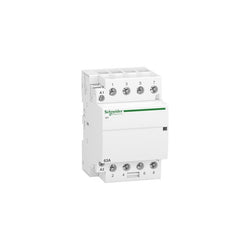
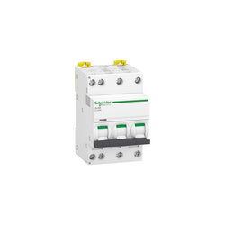
iCT 63A 4NO 220...240V 50Hz contactor
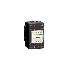
TeSys Deca contactor, 4 poles (4NO), for non-inductive load applications up to 80A/440V AC-1. They can be used to create motor starters for almost any type of application. It provides a 240V 50/60Hz AC coil, 1NO+1NC built-in auxiliary contacts (NC mirror certified), power connection by EverLink BTR screw terminals and control by screw clamp terminals. For operating rates until 3600 cycles/hour and environments until 60°C, it procures high reliability and durability. Compact (70mm width), DIN-rail mounting or screw fixing. Power contacts have a 80A resistive load rating. Multi standards certified (IEC, UL, CSA, CCC, EAC, Marine). Contactor has one normally open and one normally closed auxiliary contact built-in as standard. The NC contact is mirror certified. Screw clamp terminals are used for load and auxiliary connections. An extensive line of accessories makes it easy to meet the requirements of most applications. The contactor is 4.80 inches tall, 2.76 inches wide and 4.72 inches deep. It weighs 2.54 lbs. Contactor is certified to UL, CSA, IEC, CCC, EAC and Marine standards.
Main
| Characteristic | Value(s) |
|---|---|
| Range | TeSys TeSys Deca |
| Range of Product | TeSys Deca |
| Product or Component Type | Contactor |
| Device short name | LC1D |
| Contactor application | Resistive load |
| Utilisation category | AC-1 |
| Poles description | 4P |
| [Ue] rated operational voltage | Power circuit <= 690 V AC 25...400 Hz Power circuit <= 300 V DC |
| [Ie] rated operational current | 80 A (at <140 °F (60 °C)) at <= 440 V AC AC-1 for power circuit |
| [Uc] control circuit voltage | 240 V AC 50/60 Hz |
Complementary
| Characteristic | Value(s) |
|---|---|
| Compatibility code | LC1D |
| Pole contact composition | 4 NO |
| Protective cover | With |
| [Ith] conventional free air thermal current | 10 A (at 140 °F (60 °C)) for signalling circuit 80 A (at 140 °F (60 °C)) for power circuit |
| Irms rated making capacity | 140 A AC for signalling circuit conforming to IEC 60947-5-1 250 A DC for signalling circuit conforming to IEC 60947-5-1 1000 A at 440 V for power circuit conforming to IEC 60947 |
| Rated breaking capacity | 1000 A at 440 V for power circuit conforming to IEC 60947 |
| [Icw] rated short-time withstand current | 640 A 104 °F (40 °C) - 10 s for power circuit 900 A 104 °F (40 °C) - 1 s for power circuit 110 A 104 °F (40 °C) - 10 min for power circuit 260 A 104 °F (40 °C) - 1 min for power circuit 100 A - 1 s for signalling circuit 120 A - 500 ms for signalling circuit 140 A - 100 ms for signalling circuit |
| Associated fuse rating | 10 A gG for signalling circuit conforming to IEC 60947-5-1 125 A gG at <= 690 V coordination type 1 for power circuit 125 A gG at <= 690 V coordination type 2 for power circuit |
| Average impedance | 1.6 mOhm - Ith 80 A 50 Hz for power circuit |
| Power dissipation per pole | 10.2 W AC-1 |
| [Ui] rated insulation voltage | Power circuit 600 V CSA Power circuit 600 V UL Signalling circuit 690 V IEC 60947-1 Signalling circuit 600 V CSA Signalling circuit 600 V UL Power circuit 690 V IEC 60947-4-1 |
| Overvoltage category | III |
| pollution degree | 3 |
| [Uimp] rated impulse withstand voltage | 6 kV IEC 60947 |
| Safety reliability level | B10d = 1369863 cycles contactor with nominal load EN/ISO 13849-1 B10d = 20000000 cycles contactor with mechanical load EN/ISO 13849-1 |
| Mechanical durability | 6 Mcycles |
| Electrical durability | 1.4 Mcycles 80 A AC-1 <= 440 V |
| Control circuit type | AC 50/60 Hz |
| Coil technology | Without built-in suppressor module |
| Control circuit voltage limits | 0.3...0.6 Uc (-40â¦158 °F (-40â¦70 °C)):drop-out AC 50/60 Hz 0.8...1.1 Uc (-40â¦140 °F (-40â¦60 °C)):operational AC 50 Hz 0.85...1.1 Uc (-40â¦140 °F (-40â¦60 °C)):operational AC 60 Hz 1...1.1 Uc (140â¦158 °F (60â¦70 °C)):operational AC 50/60 Hz |
| Inrush power in VA | 140 VA 60 Hz cos phi 0.75 (at 68 °F (20 °C)) 160 VA 50 Hz cos phi 0.75 (at 68 °F (20 °C)) |
| Hold-in power consumption in VA | 13 VA 60 Hz cos phi 0.3 (at 68 °F (20 °C)) 15 VA 50 Hz cos phi 0.3 (at 68 °F (20 °C)) |
| Heat dissipation | 4â¦5 W at 50/60 Hz |
| Operating time | 4...19 ms opening 12...26 ms closing |
| Maximum operating rate | 3600 cyc/h at 60 °C |
| Connections - terminals | Control circuit: screw clamp terminals 2 0.002â¦0.004 in² (1â¦2.5 mm²) - cable stiffness: flexible with cable end Control circuit: screw clamp terminals 1 0.002â¦0.006 in² (1â¦4 mm²) - cable stiffness: flexible without cable end Control circuit: screw clamp terminals 2 0.002â¦0.006 in² (1â¦4 mm²) - cable stiffness: flexible without cable end Control circuit: screw clamp terminals 1 0.002â¦0.006 in² (1â¦4 mm²) - cable stiffness: flexible with cable end Control circuit: screw clamp terminals 1 0.002â¦0.006 in² (1â¦4 mm²) - cable stiffness: solid without cable end Control circuit: screw clamp terminals 2 0.002â¦0.006 in² (1â¦4 mm²) - cable stiffness: solid without cable end Power circuit: screw connection 1 0.002â¦0.05 in² (1â¦35 mm²) - cable stiffness: flexible without cable end Power circuit: screw connection 2 0.002â¦0.04 in² (1â¦25 mm²) - cable stiffness: flexible without cable end Power circuit: screw connection 1 0.002â¦0.05 in² (1â¦35 mm²) - cable stiffness: flexible with cable end Power circuit: screw connection 2 0.002â¦0.04 in² (1â¦25 mm²) - cable stiffness: flexible with cable end Power circuit: screw connection 1 0.002â¦0.05 in² (1â¦35 mm²) - cable stiffness: solid without cable end Power circuit: screw connection 2 0.002â¦0.04 in² (1â¦25 mm²) - cable stiffness: solid without cable end |
| Tightening torque | Control circuit 15.05 lbf.in (1.7 N.m) screw clamp terminals flat à 6 mm Control circuit 15.05 lbf.in (1.7 N.m) screw clamp terminals Philips No 2 Power circuit 70.8 lbf.in (8 N.m) screw clamp terminals 0.04â¦0.05 in² (25â¦35 mm²) hexagonal 0.2 in (4 mm) Power circuit 44.3 lbf.in (5 N.m) screw clamp terminals 0.002â¦0.04 in² (1â¦25 mm²) hexagonal 0.2 in (4 mm) Control circuit 15.05 lbf.in (1.7 N.m) screw clamp terminals pozidriv No 2 Power circuit 22.1 lbf.in (2.5 N.m) screw clamp terminals pozidriv No 2 |
| Auxiliary contact composition | 1 NO + 1 NC |
| Auxiliary contacts type | Mechanically linked 1 NO + 1 NC IEC 60947-5-1 Mirror contact 1 NC IEC 60947-4-1 |
| Signalling circuit frequency | 25...400 Hz |
| Minimum switching voltage | 17 V for signalling circuit |
| Minimum switching current | 5 mA for signalling circuit |
| Insulation resistance | > 10 MOhm for signalling circuit |
| Non-overlap time | 1.5 ms on de-energisation between NC and NO contact 1.5 ms on energisation between NC and NO contact |
| Mounting Support | Plate Rail |
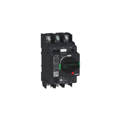
Motor circuit breaker, TeSys GV4, 3P, 80A, Icu 25kA, thermal magnetic, lugs terminals

Reflex iC60H Ti24 25 A 3P curve B integrated control MCB
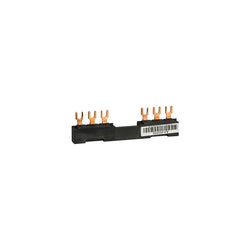
Linergy FT - Comb busbar - 63 A - 2 tap-offs - 72 mm pitch
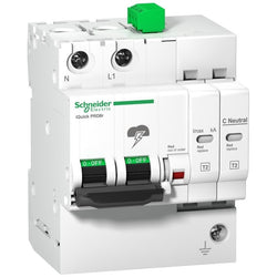
iQuick PRD40r modular surge arrester - 1 pole + N - 350V - with remote transfer

TeSys GV motor circuit breaker, 3 poles (3P), 50A/690V, for protection of 3-phase motors 11-22kW@400V. It provides thermal magnetic protection and additional motor protection functions, breaking capacity Icu 25kA@400V, start-stop control by rotary handle, connection for bars or cables with lugs. Thermal protection adjustable by dials with a setting current Ir in range 20-50A and a selectable tripping class 10 or 20, magnetic protection at 17 In. Additional protections have fixed pick-up and include short time delay protection Isd at 13 Ir, phase unbalance and loss protection, ground fault protection. It makes internal locations available for additional auxiliary contact blocks (OF, SD), and voltage trip units (MN, MX). Multi standards certified (IEC, UL, CSA, CCC, EAC, Marine, ATEX), Green Premium compliant (RoHS/REACh).
Main
| Characteristic | Value(s) |
|---|---|
| Range of Product | TeSys GV4 |
| Range | TeSys Deca |
| Device short name | GV4P |
| product name | TeSys GV4 |
| Product or Component Type | Motor circuit breaker |
| Device Application | Motor protection |
| Trip unit technology | Thermal-magnetic Electronic |
Complementary
| Characteristic | Value(s) |
|---|---|
| Poles description | 3P |
| Utilisation category | Category A IEC 60947-2 AC-3 IEC 60947-4-1 |
| Operating position | Any position |
| Motor power kW | 11 kW 400...415 V AC 50/60 Hz 15 kW 500 V AC 50/60 Hz 18.5 kW 660...690 V AC 50/60 Hz 15 kW 400...415 V AC 50/60 Hz 18.5 kW 400...415 V AC 50/60 Hz 22 kW 400...415 V AC 50/60 Hz 18.5 kW 500 V AC 50/60 Hz 22 kW 500 V AC 50/60 Hz 30 kW 500 V AC 50/60 Hz 22 kW 660...690 V AC 50/60 Hz 30 kW 660...690 V AC 50/60 Hz 37 kW 660...690 V AC 50/60 Hz 45 kW 660...690 V AC 50/60 Hz |
| Breaking capacity | 50 kA Icu 220...240 V AC 50/60 Hz IEC 60947-2 25 kA Icu 380...415 V AC 50/60 Hz IEC 60947-2 20 kA Icu 440 V AC 50/60 Hz IEC 60947-2 10 kA Icu 500 V AC 50/60 Hz IEC 60947-2 35 kA 208Y/120 V AC 50/60 Hz UL 60947 35 kA 240 V AC 50/60 Hz UL 60947 18 kA 480Y/277 V AC 50/60 Hz UL 60947 14 kA 600Y/347 V AC 50/60 Hz UL 60947 |
| Control Type | Rotary handle |
| Line Rated Current | 50 A |
| Magnetic tripping current | 850 A |
| [Ue] rated operational voltage | 690 V AC 50/60 Hz IEC 60947-2 |
| [Ui] rated insulation voltage | 800 V AC 50/60 Hz IEC 60947-2 |
| [Ith] conventional free air thermal current | 115 A IEC 60947-4-1 |
| [Uimp] rated impulse withstand voltage | 8 kV IEC 60947-2 |
| Power dissipation per pole | 4.6 W |
| Mechanical durability | 40000 cycles |
| Electrical durability | 20000 cycles AC-3 440 V In/2 10000 cycles AC-3 440 V In |
| Maximum operating rate | 25 cyc/h |
| Rated duty | Continuous IEC 60947-4-1 |
| Connection pitch | 1.06 in (27 mm) without spreaders 1.4 in (35 mm) with spreaders |
| Connections - terminals | Lugs-ring terminals |
| Tightening torque | 79.7 lbf.in (9 N.m) 0.02â¦0.1 in² (16â¦95 mm²) 44.3 lbf.in (5 N.m) 0.002â¦0.02 in² (1.5â¦10 mm²) |
| Mechanical robustness | Vibrations +/- 1 mm 2...13.2 Hz IEC 60068-2-6 Vibrations 0.7 gn 13.2...100 Hz IEC 60068-2-6 Shocks 15 gn 11 ms IEC 60068-2-27 |
| Phase failure sensitivity | Yes IEC 60947-4-1 |
| Height | 6.1 in (155 mm) |
| Width | 3.2 in (81 mm) |
| Depth | 6.5 in (165 mm) |
| Product Weight | 3.5 lb(US) (1.6 kg) |
| color | Gray RAL 7016) |
| Suitability for isolation | Yes IEC 60947-1 |

TeSys D contactor - 3P(3 NO) - AC-3 - <= 440 V 65 A - 208 V AC 60 Hz coil
DIN rail mounting base - 22 mm units - for control and signalling unit

TeSys K contactor - 3P - AC-3 <= 440 V 6 A - 1 NO aux. - 72 V DC low

TeSys GV motor circuit breaker, 3 poles (3P), 3.5A/690V, for protection of 3-phase motors 0.55-1.5kW@400V. Multifunction circuit breaker, it provides thermal magnetic protection and advanced motor protection, breaking capacity Icu 50kA@400V, start-stop control by toggle, connection by Everlink BTR screw terminals. Thermal protection adjustable by dials with a setting current Ir in range 1.4-3.5A and a selectable tripping class 10 or 20, magnetic protection at 17 In. Advanced protections are adjustable with a smartphone using wireless NFC and include short time delay protection Isd with a setting range 5-13 Ir, phase unbalance and loss protection, ground fault protection, locked rotor (jam), long start. It makes internal locations available for additional auxiliary contact blocks (OF, SD), and voltage trip units (MN, MX). It can be equiped externally with 1 or 2 auxiliary SDx modules in order to have alarming and fault differentiation. Multi standards certified (IEC, UL, CSA, CCC, EAC, Marine, ATEX).
Main
| Characteristic | Value(s) |
|---|---|
| Range of Product | TeSys GV4 |
| Range | TeSys Deca |
| Device short name | GV4PEM |
| product name | TeSys GV4 |
| Product or Component Type | Motor circuit breaker |
| Device Application | Motor protection |
| Trip unit technology | Thermal-magnetic Electronic |
Complementary
| Characteristic | Value(s) |
|---|---|
| Poles description | 3P |
| Utilisation category | Category A IEC 60947-2 AC-3 IEC 60947-4-1 |
| Operating position | Any position |
| Motor power kW | 0.55 kW 400...415 V AC 50/60 Hz 0.75 kW 400...415 V AC 50/60 Hz 0.75 kW 500 V AC 50/60 Hz 1.1 kW 500 V AC 50/60 Hz 1.1 kW 660...690 V AC 50/60 Hz 1.5 kW 660...690 V AC 50/60 Hz 1.5 kW 500 V AC 50/60 Hz 2.2 kW 660...690 V AC 50/60 Hz 1.1 kW 400...415 V AC 50/60 Hz 1.5 kW 400...415 V AC 50/60 Hz |
| Breaking capacity | 100 kA Icu 220...240 V AC 50/60 Hz IEC 60947-2 50 kA Icu 380...415 V AC 50/60 Hz IEC 60947-2 50 kA Icu 440 V AC 50/60 Hz IEC 60947-2 15 kA Icu 525 V AC 50/60 Hz IEC 60947-2 65 kA 208Y/120 V AC 50/60 Hz UL 60947 65 kA 240 V AC 50/60 Hz UL 60947 35 kA 480Y/277 V AC 50/60 Hz UL 60947 8 kA Icu 660...690 V AC 50/60 Hz IEC 60947-2 25 kA Icu 500 V AC 50/60 Hz IEC 60947-2 18 kA 600Y/347 V AC 50/60 Hz UL 60947 |
| Control Type | Toggle |
| Line Rated Current | 3.5 A |
| Magnetic tripping current | 59 A |
| [Ue] rated operational voltage | 690 V AC 50/60 Hz IEC 60947-2 |
| [Ui] rated insulation voltage | 800 V AC 50/60 Hz IEC 60947-2 |
| [Ith] conventional free air thermal current | 115 A IEC 60947-4-1 |
| [Uimp] rated impulse withstand voltage | 8 kV IEC 60947-2 |
| Power dissipation per pole | 4.6 W |
| Mechanical durability | 40000 cycles |
| Electrical durability | 40000 cycles AC-3 440 V In/2 40000 cycles AC-3 440 V In |
| Maximum operating rate | 25 cyc/h |
| Rated duty | Continuous IEC 60947-4-1 |
| Connections - terminals | EverLink BTR screw connectors top) 1 0.002â¦0.1 in² (1.5â¦70 mm²) - solid EverLink BTR screw connectors top) 1 0.002â¦0.08 in² (1.5â¦50 mm²) - flexible EverLink BTR screw connectors bottom) 1 0.004â¦0.1 in² (2.5â¦95 mm²) - solid EverLink BTR screw connectors bottom) 1 0.004â¦0.1 in² (2.5â¦70 mm²) - flexible |
| Tightening torque | 79.7 lbf.in (9 N.m) 0.02â¦0.1 in² (16â¦95 mm²) 44.3 lbf.in (5 N.m) 0.002â¦0.02 in² (1.5â¦10 mm²) |
| Mechanical robustness | Vibrations +/- 1 mm 2...13.2 Hz IEC 60068-2-6 Vibrations 0.7 gn 13.2...100 Hz IEC 60068-2-6 Shocks 15 gn 11 ms IEC 60068-2-27 |
| Phase failure sensitivity | Yes IEC 60947-4-1 |
| Height | 6.1 in (155 mm) |
| Width | 3.2 in (81 mm) |
| Depth | 4.6 in (116 mm) |
| Product Weight | 3.20 lb(US) (1.45 kg) |
| color | Gray RAL 7016) |
| Suitability for isolation | Yes IEC 60947-1 |

TeSys GV motor circuit breaker, 3 poles (3P), 25A/690V, for 3-phase motor applications 11kW@400V. It provides a thermal-magnetic protection with a thermal setting range 20-25A, magnetic tripping at 13xIn, high breaking capacity Icu 15kA@400V. Connection by lugs. Start-stop control by push-button guaranteed for 100 000 cycles AC-3. Multi standards certified (IEC, UL, CSA, CCC, EAC, Marine, ATEX),
Main
| Characteristic | Value(s) |
|---|---|
| Range | TeSys Deca |
| product name | TeSys GV2 |
| Product or component type | Motor circuit breaker |
| Device short name | GV2ME |
| Device application | Motor protection |
| Trip unit technology | Thermal-magnetic |
Complementary
| Characteristic | Value(s) |
|---|---|
| Poles description | 3P |
| Network type | AC |
| Utilisation category | Category A conforming to IEC 60947-2 AC-3 conforming to IEC 60947-4-1 AC-3e conforming to IEC 60947-4-1 |
| Network frequency | 50/60 Hz conforming to IEC 60947-2 |
| Motor power kW | 11 kW at 400/415 V AC 50/60 Hz 15 kW at 500 V AC 50/60 Hz |
| Breaking capacity | 50 kA Icu at 230/240 V AC 50/60 Hz conforming to IEC 60947-2 15 kA Icu at 400/415 V AC 50/60 Hz conforming to IEC 60947-2 6 kA Icu at 440 V AC 50/60 Hz conforming to IEC 60947-2 4 kA Icu at 500 V AC 50/60 Hz conforming to IEC 60947-2 3 kA Icu at 690 V AC 50/60 Hz conforming to IEC 60947-2 |
| [Ics] rated service short-circuit breaking capacity | 100 % at 230/240 V AC 50/60 Hz conforming to IEC 60947-2 40 % at 400/415 V AC 50/60 Hz conforming to IEC 60947-2 50 % at 440 V AC 50/60 Hz conforming to IEC 60947-2 75 % at 500 V AC 50/60 Hz conforming to IEC 60947-2 75 % at 690 V AC 50/60 Hz conforming to IEC 60947-2 |
| control type | Push-button |
| [In] rated current | 25 A |
| Thermal protection adjustment range | 20â¦25 A conforming to IEC 60947-2 |
| Magnetic tripping current | 388.3 A |
| [Ith] conventional free air thermal current | 25 A conforming to IEC 60947-2 |
| [Ue] rated operational voltage | 690 V AC 50/60 Hz conforming to IEC 60947-2 |
| [Ui] rated insulation voltage | 690 V AC 50/60 Hz conforming to IEC 60947-2 |
| [Uimp] rated impulse withstand voltage | 6 kV conforming to IEC 60947-2 |
| Phase failure sensitivity | Yes conforming to IEC 60947-4-1 |
| Suitability for isolation | Yes conforming to IEC 60947-1 |
| Power dissipation per pole | 2.5 W |
| Mechanical durability | 100000 cycles |
| Electrical durability | 100000 cycles for AC-3 at 415 V In 100000 cycles for AC-3e at 415 V In |
| Rated duty | Uninterrupted conforming to IEC 60947-4-1 |
| Connections - terminals | Power circuit: lugs-ring terminals 2 cable(s) 1â¦6 mm²solid Power circuit: lugs-ring terminals 2 cable(s) 1.5â¦6 mm²flexible without cable end Power circuit: lugs-ring terminals 2 cable(s) 1â¦4 mm²flexible with cable end |
| Tightening torque | 1.7 N.m - on screw clamp terminal |
| Fixing mode | 35 mm symmetrical DIN rail: clipped Panel: screwed (with adaptor plate) |
| Mounting position | Horizontal Vertical |
| Width | 45 mm |
| Height | 89 mm |
| Depth | 78.5 mm |
| Product weight | 0.26 kg |
| Colour | Dark grey |
| Connection pitch | 13.5 mm without spreader |
Acti9 iC40N - miniature circuit-breaker - 3P+N - 32A - B Curve - 6000A/10kA

TeSys Deca contactor, 4 poles (2NO+2NC), for non-inductive load applications up to 40A/690V AC-1. They can be used to create motor starters for almost any type of application. It provides a 42V 50/60Hz AC coil, 1NO+1NC built-in auxiliary contacts (NC mirror certified), connection by screw clamp terminals. For operating rates until 3600 cycles/hour and environments until 60°C, it procures high reliability and durability. Compact (45mm width), DIN-rail mounting or screw fixing. Power contacts have a 40A resistive load rating. Multi standards certified (IEC, UL, CSA, CCC, EAC, Marine). Contactor has one normally open and one normally closed auxiliary contact built-in as standard. The NC contact is mirror certified. Screw clamp terminals are used for load and auxiliary connections. An extensive line of accessories makes it easy to meet the requirements of most applications. The contactor is 4.13 inches tall, 1.77 inches wide and 3.90 inches deep. It weighs 0.94 lbs. Contactor is certified to UL, CSA, IEC, CCC, EAC and Marine standards.
Main
| Characteristic | Value(s) |
|---|---|
| Range of Product | TeSys Deca |
| Product or Component Type | Contactor |
| Device short name | LC1D |
| Contactor application | Resistive load |
| Utilisation category | AC-1 |
| Poles description | 4P |
| [Ue] rated operational voltage | Power circuit <= 690 V AC 25...400 Hz |
| [Ie] rated operational current | 40 A (at <140 °F (60 °C)) at <= 440 V AC AC-1 for power circuit |
| [Uc] control circuit voltage | 42 V AC 50/60 Hz |
Complementary
| Characteristic | Value(s) |
|---|---|
| Compatibility code | LC1D |
| Pole contact composition | 2 NO + 2 NC |
| Protective cover | With |
| [Ith] conventional free air thermal current | 10 A (at 140 °F (60 °C)) for signalling circuit 40 A (at 140 °F (60 °C)) for power circuit |
| Irms rated making capacity | 140 A AC for signalling circuit conforming to IEC 60947-5-1 250 A DC for signalling circuit conforming to IEC 60947-5-1 450 A at 440 V for power circuit conforming to IEC 60947 |
| Rated breaking capacity | 450 A at 440 V for power circuit conforming to IEC 60947 |
| [Icw] rated short-time withstand current | 240 A 104 °F (40 °C) - 10 s for power circuit 380 A 104 °F (40 °C) - 1 s for power circuit 50 A 104 °F (40 °C) - 10 min for power circuit 120 A 104 °F (40 °C) - 1 min for power circuit 100 A - 1 s for signalling circuit 120 A - 500 ms for signalling circuit 140 A - 100 ms for signalling circuit |
| Associated fuse rating | 10 A gG for signalling circuit conforming to IEC 60947-5-1 63 A gG at <= 690 V coordination type 1 for power circuit 40 A gG at <= 690 V coordination type 2 for power circuit |
| Average impedance | 2 mOhm - Ith 40 A 50 Hz for power circuit |
| Power dissipation per pole | 3.2 W AC-1 |
| [Ui] rated insulation voltage | Power circuit 690 V IEC 60947-4-1 Power circuit 600 V CSA Power circuit 600 V UL Signalling circuit 690 V IEC 60947-1 Signalling circuit 600 V CSA Signalling circuit 600 V UL |
| Overvoltage category | III |
| pollution degree | 3 |
| [Uimp] rated impulse withstand voltage | 6 kV IEC 60947 |
| Safety reliability level | B10d = 1369863 cycles contactor with nominal load EN/ISO 13849-1 B10d = 20000000 cycles contactor with mechanical load EN/ISO 13849-1 |
| Mechanical durability | 15 Mcycles |
| Electrical durability | 1.4 Mcycles 40 A AC-1 <= 440 V |
| Control circuit type | AC 50/60 Hz |
| Coil technology | Without built-in suppressor module |
| Control circuit voltage limits | 0.3...0.6 Uc (-40â¦140 °F (-40â¦60 °C)):drop-out AC 50/60 Hz 0.8...1.1 Uc (-40â¦140 °F (-40â¦60 °C)):operational AC 50 Hz 0.85...1.1 Uc (-40â¦140 °F (-40â¦60 °C)):operational AC 60 Hz |
| Inrush power in VA | 70 VA 60 Hz cos phi 0.75 (at 68 °F (20 °C)) 70 VA 50 Hz cos phi 0.75 (at 68 °F (20 °C)) |
| Hold-in power consumption in VA | 7.5 VA 60 Hz cos phi 0.3 (at 68 °F (20 °C)) 7 VA 50 Hz cos phi 0.3 (at 68 °F (20 °C)) |
| Heat dissipation | 2â¦3 W at 50/60 Hz |
| Operating time | 12...22 ms closing 4...19 ms opening |
| Maximum operating rate | 3600 cyc/h at 60 °C |
| Connections - terminals | Control circuit: screw clamp terminals 1 0.002â¦0.006 in² (1â¦4 mm²) - cable stiffness: flexible without cable end Control circuit: screw clamp terminals 2 0.002â¦0.006 in² (1â¦4 mm²) - cable stiffness: flexible without cable end Control circuit: screw clamp terminals 1 0.002â¦0.006 in² (1â¦4 mm²) - cable stiffness: flexible with cable end Control circuit: screw clamp terminals 2 0.002â¦0.004 in² (1â¦2.5 mm²) - cable stiffness: flexible with cable end Control circuit: screw clamp terminals 1 0.002â¦0.006 in² (1â¦4 mm²) - cable stiffness: solid without cable end Control circuit: screw clamp terminals 2 0.002â¦0.006 in² (1â¦4 mm²) - cable stiffness: solid without cable end Power circuit: screw clamp terminals 1 0.004â¦0.02 in² (2.5â¦10 mm²) - cable stiffness: flexible without cable end Power circuit: screw clamp terminals 2 0.004â¦0.02 in² (2.5â¦10 mm²) - cable stiffness: flexible without cable end Power circuit: screw clamp terminals 1 0.004â¦0.02 in² (2.5â¦10 mm²) - cable stiffness: flexible with cable end Power circuit: screw clamp terminals 2 0.004â¦0.02 in² (2.5â¦10 mm²) - cable stiffness: flexible with cable end Power circuit: screw clamp terminals 1 0.004â¦0.02 in² (2.5â¦16 mm²) - cable stiffness: solid without cable end Power circuit: screw clamp terminals 2 0.004â¦0.02 in² (2.5â¦16 mm²) - cable stiffness: solid without cable end |
| Tightening torque | Control circuit 15.05 lbf.in (1.7 N.m) screw clamp terminals flat à 6 mm Control circuit 15.05 lbf.in (1.7 N.m) screw clamp terminals Philips No 2 Control circuit 15.05 lbf.in (1.7 N.m) screw clamp terminals pozidriv No 2 Power circuit 15.9 lbf.in (1.8 N.m) screw clamps terminals flat à 6 mm Power circuit 15.9 lbf.in (1.8 N.m) screw clamps terminals Philips No 2 Power circuit 15.9 lbf.in (1.8 N.m) screw clamp terminals pozidriv No 2 |
| Auxiliary contact composition | 1 NO + 1 NC |
| Auxiliary contacts type | Mechanically linked 1 NO + 1 NC IEC 60947-5-1 Mirror contact 1 NC IEC 60947-4-1 |
| Signalling circuit frequency | 25...400 Hz |
| Minimum switching voltage | 17 V for signalling circuit |
| Minimum switching current | 5 mA for signalling circuit |
| Insulation resistance | > 10 MOhm for signalling circuit |
| Non-overlap time | 1.5 ms on de-energisation between NC and NO contact 1.5 ms on energisation between NC and NO contact |
| Mounting Support | Rail Plate |

TeSys GV motor circuit breaker, 3 poles (3P), 50A/690V, for protection of 3-phase motors 11-22kW@400V. Multifunction circuit breaker, it provides thermal magnetic protection and advanced motor protection, breaking capacity Icu 25kA@400V, start-stop control by toggle, connection by Everlink BTR screw terminals. Thermal protection adjustable by dials with a setting current Ir in range 20-50A and a selectable tripping class 10 or 20, magnetic protection at 17 In. Advanced protections are adjustable with a smartphone using wireless NFC and include short time delay protection Isd with a setting range 5-13 Ir, phase unbalance and loss protection, ground fault protection, locked rotor (jam), long start. It makes internal locations available for additional auxiliary contact blocks (OF, SD), and voltage trip units (MN, MX). It can be equiped externally with 1 or 2 auxiliary SDx modules in order to have alarming and fault differentiation. Multi standards certified (IEC, UL, CSA, CCC, EAC, Marine, ATEX), Green Premium compliant (RoHS/REACh).
Main
| Characteristic | Value(s) |
|---|---|
| Range of Product | TeSys GV4 |
| Range | TeSys Deca |
| Device short name | GV4PEM |
| product name | TeSys GV4 |
| Product or Component Type | Motor circuit breaker |
| Device Application | Motor protection |
| Trip unit technology | Thermal-magnetic Electronic |
Complementary
| Characteristic | Value(s) |
|---|---|
| Poles description | 3P |
| Utilisation category | Category A IEC 60947-2 AC-3 IEC 60947-4-1 |
| Operating position | Any position |
| Motor power kW | 11 kW 400...415 V AC 50/60 Hz 15 kW 500 V AC 50/60 Hz 18.5 kW 660...690 V AC 50/60 Hz 15 kW 400...415 V AC 50/60 Hz 18.5 kW 400...415 V AC 50/60 Hz 22 kW 400...415 V AC 50/60 Hz 18.5 kW 500 V AC 50/60 Hz 22 kW 500 V AC 50/60 Hz 30 kW 500 V AC 50/60 Hz 22 kW 660...690 V AC 50/60 Hz 30 kW 660...690 V AC 50/60 Hz 37 kW 660...690 V AC 50/60 Hz 45 kW 660...690 V AC 50/60 Hz |
| Breaking capacity | 50 kA Icu 220...240 V AC 50/60 Hz IEC 60947-2 25 kA Icu 380...415 V AC 50/60 Hz IEC 60947-2 20 kA Icu 440 V AC 50/60 Hz IEC 60947-2 10 kA Icu 500 V AC 50/60 Hz IEC 60947-2 35 kA 208Y/120 V AC 50/60 Hz UL 60947 35 kA 240 V AC 50/60 Hz UL 60947 18 kA 480Y/277 V AC 50/60 Hz UL 60947 14 kA 600Y/347 V AC 50/60 Hz UL 60947 |
| Control Type | Toggle |
| Line Rated Current | 50 A |
| Magnetic tripping current | 850 A |
| [Ue] rated operational voltage | 690 V AC 50/60 Hz IEC 60947-2 |
| [Ui] rated insulation voltage | 800 V AC 50/60 Hz IEC 60947-2 |
| [Ith] conventional free air thermal current | 115 A IEC 60947-4-1 |
| [Uimp] rated impulse withstand voltage | 8 kV IEC 60947-2 |
| Power dissipation per pole | 4.6 W |
| Mechanical durability | 40000 cycles |
| Electrical durability | 20000 cycles AC-3 440 V In/2 10000 cycles AC-3 440 V In |
| Maximum operating rate | 25 cyc/h |
| Rated duty | Continuous IEC 60947-4-1 |
| Connections - terminals | EverLink BTR screw connectors top) 1 0.002â¦0.1 in² (1.5â¦70 mm²) - solid EverLink BTR screw connectors top) 1 0.002â¦0.08 in² (1.5â¦50 mm²) - flexible EverLink BTR screw connectors bottom) 1 0.004â¦0.1 in² (2.5â¦95 mm²) - solid EverLink BTR screw connectors bottom) 1 0.004â¦0.1 in² (2.5â¦70 mm²) - flexible |
| Tightening torque | 79.7 lbf.in (9 N.m) 0.02â¦0.1 in² (16â¦95 mm²) 44.3 lbf.in (5 N.m) 0.002â¦0.02 in² (1.5â¦10 mm²) |
| Mechanical robustness | Vibrations +/- 1 mm 2...13.2 Hz IEC 60068-2-6 Vibrations 0.7 gn 13.2...100 Hz IEC 60068-2-6 Shocks 15 gn 11 ms IEC 60068-2-27 |
| Phase failure sensitivity | Yes IEC 60947-4-1 |
| Height | 6.1 in (155 mm) |
| Width | 3.2 in (81 mm) |
| Depth | 4.6 in (116 mm) |
| Product Weight | 3.20 lb(US) (1.45 kg) |
| color | Gray RAL 7016) |
| Suitability for isolation | Yes IEC 60947-1 |