
 1 year warranty

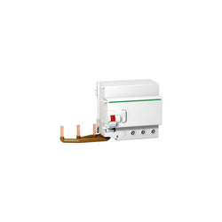
This Acti9 Vigi C120 is a modular add-on residual current devices. It has 3P with 3 protected poles, rated current is 125A and operating voltage is 230VAC to 415VAC. The earth leakage protection class is A type with a sensitivity of 300mA and a voltage independent technology. This product protects against short circuit, cable overload, electrical shock by indirect contact and fire hazards. This product is compliant with EN 61009 standard. Electrical endurance goes up to 20000 cycles. The Ue rated operational voltage is from 230VAC to 415VAC. The Ui rated insulation voltage is 500VAC. The Uimp rated impulse withstand voltage is 6kV. The pollution degree is 3. It can be mounted on 35 mm symmetrical DIN rail. The width in 9mm pitches is 10. The product color is white (RAL9003). The dimensions are (W) 171mm x (H) 95mm x (D) 73mm. The weight is 0.5kg. The degree of protection is IP20 and IP40 in an enclosure. The operating temperature is -25°C to 60°C. The storage temperature is -40°C to 60°C.
Main
| Characteristic | Value(s) |
|---|---|
| Range | Acti9 |
| product name | Acti9 Vigi C120 |
| Product or component type | Add-on residual current device |
| Device short name | Vigi C120 |
| Poles description | 3P |
| [In] rated current | 125 A |
| Network type | AC |
| Earth-leakage sensitivity | 300 mA |
| Earth-leakage protection time delay | Instantaneous |
| Earth-leakage protection class | Type A |
| Standards | EN 61009 IEC/EN 61009-2-1 |
Complementary
| Characteristic | Value(s) |
|---|---|
| Device location in system | Outgoer Group incomer |
| Network frequency | 50/60 Hz |
| [Ue] rated operational voltage | 230...415 V AC 50/60 Hz |
| Residual current tripping technology | Voltage independent |
| [Ui] rated insulation voltage | 500 V AC 50/60 Hz conforming to IEC 60947-1 |
| [Uimp] rated impulse withstand voltage | 6 kV conforming to IEC 60947-2 |
| Mounting mode | Clip-on |
| Mounting support | 35 mm symmetrical DIN rail |
| Electrical connection to mcb | By screws |
| 9 mm pitches | 10 |
| Height | 95 mm |
| Width | 171 mm |
| Depth | 73 mm |
| Product weight | 0.5 kg |
| Colour | White |
| Mechanical durability | 20000 cycles |
| Connections - terminals | Tunnel type terminals 1â¦35 mm² flexible Tunnel type terminals 1â¦50 mm² rigid |
| Wire stripping length | 15 mm |
| Tightening torque | 3.5 N.m |

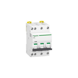
This Acti9 iC40N product is a low voltage miniature circuit breaker (MCB). It is a 3P+N circuit breaker with 3 protected poles and 16A In rated current and C tripping curve. The rated short circuit breaking capacity goes up to 10kA at 400VAC conforming to EN/IEC 60947-2 standard and 6000A at 400VAC conforming to EN/IEC 60898-1 standard. This product complies with both industrial standard EN/IEC 60898-1 and residential standard EN/IEC 60947-2. This miniature circuit breaker combines functions of circuit protection against short circuit and overload current, control and isolation. The installation and cabling are simplified with clip on function as well as ease of maintenance. It has an electrical endurance going up to 20000 cycles and a mechanical endurance going up to 20000 cycles. The Ue operational voltage is 400VAC. The Ui rated insulation voltage is 440VAC. The Uimp rated impulse withstand voltage is 4kV. The operating frequency is 50Hz or 60Hz. It can be mounted on DIN rail for modular installation. Its width is 6 pitches of 9mm. Pollution degree is 3. The product colour is white (RAL9003). The dimensions are (W) 54mm x (H) 85mm x (D) 74mm. The weight is 345g. According to IEC 60529 standard, the degree of protection is IP20 and IP40 in enclosure. The operating temperature is -25°C to 70°C. The storage temperature is -40°C to 85°C.
Main
| Characteristic | Value(s) |
|---|---|
| Range | Acti9 |
| product name | Acti9 iC40 |
| Product or component type | Miniature circuit-breaker |
| Device short name | iC40N |
| Device application | Distribution |
| Poles description | 3P + N |
| Number of protected poles | 3 |
| Neutral position | Left |
| [In] rated current | 16 A |
| Network type | AC |
| Trip unit technology | Thermal-magnetic |
| Curve code | C |
| Breaking capacity | 10 kA Icu at 400 V AC 50/60 Hz conforming to EN/IEC 60947-2 6000 A Icn at 400 V AC 50/60 Hz conforming to EN/IEC 60898-1 |
| Suitability for isolation | Yes conforming to EN/IEC 60947-2 |
| Quality labels | OVE IMQ AENOR |
Complementary
| Characteristic | Value(s) |
|---|---|
| Network frequency | 50/60 Hz |
| [Ue] rated operational voltage | 400 V AC 50/60 Hz |
| Magnetic tripping limit | 5...10 x In conforming to EN/IEC 60898-1 8 x In +/- 20 % conforming to EN/IEC 60947-2 |
| [Ics] rated service breaking capacity | 6000 A 100 % x Icn at 400 V AC 50/60 Hz conforming to EN/IEC 60898-1 7.5 kA 75 % x Icn at 400 V AC 50/60 Hz conforming to EN/IEC 60947-2 |
| Limitation class | 3 conforming to EN/IEC 60898-1 |
| [Ui] rated insulation voltage | 440 V AC 50/60 Hz conforming to EN/IEC 60947-2 |
| [Uimp] rated impulse withstand voltage | 4 kV conforming to EN/IEC 60947-2 |
| Contact position indicator | Yes |
| control type | Toggle |
| Local signalling | ON/OFF indication Trip indicator |
| Mounting mode | Clip-on |
| Mounting support | DIN rail |
| 9 mm pitches | 6 |
| Height | 85 mm |
| Width | 54 mm |
| Depth | 74 mm |
| Product weight | 345 g |
| Colour | White |
| Mechanical durability | 20000 cycles |
| Electrical durability | 20000 cycles |
| Locking options description | Padlocking device |
| Connections - terminals | Tunnel type terminals top or bottom 1â¦10 mm² flexible Tunnel type terminals top or bottom 1â¦16 mm² rigid |
| Wire stripping length | 14 mm for top or bottom connection |
| Tightening torque | 2 N.m top or bottom |
| Earth-leakage protection | Separate block |
Acti9 iC40N - miniature circuit-breaker - 3P+N - 20A - B Curve - 6000A/10kA


C120N - circuit breaker - 3P - 125A - D curve

This Acti9 iC40N product is a low voltage miniature circuit breaker (MCB). It is a 3P+N circuit breaker with 3 protected poles and 16A In rated current and B tripping curve. The rated short circuit breaking capacity goes up to 10kA at 400VAC conforming to EN/IEC 60947-2 standard and 6000A at 400VAC conforming to EN/IEC 60898-1 standard. This product complies with both industrial standard EN/IEC 60898-1 and residential standard EN/IEC 60947-2. This miniature circuit breaker combines functions of circuit protection against short circuit and overload current, control and isolation. The installation and cabling are simplified with clip on function as well as ease of maintenance. It has an electrical endurance going up to 20000 cycles and a mechanical endurance going up to 20000 cycles. The Ue operational voltage is 400VAC. The Ui rated insulation voltage is 440VAC. The Uimp rated impulse withstand voltage is 4kV. The operating frequency is 50Hz or 60Hz. It can be mounted on DIN rail for modular installation. Its width is 6 pitches of 9mm. Pollution degree is 3. The product colour is white (RAL9003). The dimensions are (W) 54mm x (H) 85mm x (D) 74mm. The weight is 345g. According to IEC 60529 standard, the degree of protection is IP20 and IP40 in enclosure. The operating temperature is -25°C to 70°C. The storage temperature is -40°C to 85°C.
Main
| Characteristic | Value(s) |
|---|---|
| Range | Acti9 |
| product name | Acti9 iC40 |
| Product or component type | Miniature circuit-breaker |
| Device short name | iC40N |
| Device application | Distribution |
| Poles description | 3P + N |
| Number of protected poles | 3 |
| Neutral position | Left |
| [In] rated current | 16 A |
| Network type | AC |
| Trip unit technology | Thermal-magnetic |
| Curve code | B |
| Breaking capacity | 10 kA Icu at 400 V AC 50/60 Hz conforming to EN/IEC 60947-2 6000 A Icn at 400 V AC 50/60 Hz conforming to EN/IEC 60898-1 |
| Suitability for isolation | Yes conforming to EN/IEC 60947-2 |
| Quality labels | IMQ OVE |
Complementary
| Characteristic | Value(s) |
|---|---|
| Network frequency | 50/60 Hz |
| [Ue] rated operational voltage | 400 V AC 50/60 Hz |
| Magnetic tripping limit | 3...5 x In conforming to EN/IEC 60898-1 4 x In +/- 20 % conforming to EN/IEC 60947-2 |
| [Ics] rated service breaking capacity | 6000 A 100 % x Icn at 400 V AC 50/60 Hz conforming to EN/IEC 60898-1 7.5 kA 75 % x Icn at 400 V AC 50/60 Hz conforming to EN/IEC 60947-2 |
| Limitation class | 3 conforming to EN/IEC 60898-1 |
| [Ui] rated insulation voltage | 440 V AC 50/60 Hz conforming to EN/IEC 60947-2 |
| [Uimp] rated impulse withstand voltage | 4 kV conforming to EN/IEC 60947-2 |
| Contact position indicator | Yes |
| control type | Toggle |
| Local signalling | ON/OFF indication Trip indicator |
| Mounting mode | Clip-on |
| Mounting support | DIN rail |
| 9 mm pitches | 6 |
| Height | 85 mm |
| Width | 54 mm |
| Depth | 74 mm |
| Product weight | 345 g |
| Colour | White |
| Mechanical durability | 20000 cycles |
| Electrical durability | 20000 cycles |
| Locking options description | Padlocking device |
| Connections - terminals | Tunnel type terminals top or bottom 1â¦10 mm² flexible Tunnel type terminals top or bottom 1â¦16 mm² rigid |
| Wire stripping length | 14 mm for top or bottom connection |
| Tightening torque | 2 N.m top or bottom |
| Earth-leakage protection | Separate block |
Main
| Characteristic | Value(s) |
|---|---|
| Range | TeSys |
| Range of product | TeSys Deca |
| Product or component type | Contactor |
| Device short name | LC1D |
| Contactor application | Motor control Resistive load |
| Utilisation category | AC-3 AC-3e AC-4 AC-1 |
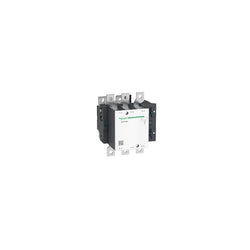
| Poles description | 3P |
| [Ue] rated operational voltage | Power circuit: <= 300 V DC 25...400 Hz Power circuit: <= 690 V AC |
| [Ie] rated operational current | 125 A (at <60 °C) at <= 1000 V AC AC-1 for power circuit 80 A (at <60 °C) at <= 440 V AC AC-3 for power circuit 80 A (at <60 °C) at <= 440 V AC AC-3e for power circuit |
| [Uc] control circuit voltage | 110 V DC |
Complementary
| Characteristic | Value(s) |
|---|---|
| Motor power kW | 22 kW at 220...230 V AC 50/60 Hz (AC-3) 37 kW at 380...400 V AC 50/60 Hz (AC-3) 45 kW at 415...440 V AC 50/60 Hz (AC-3) 55 kW at 500 V AC 50/60 Hz (AC-3) 45 kW at 660...690 V AC 50/60 Hz (AC-3) 15 kW at 400 V AC 50/60 Hz (AC-4) 22 kW at 220...230 V AC 50/60 Hz (AC-3e) 37 kW at 380...400 V AC 50/60 Hz (AC-3e) 45 kW at 415...440 V AC 50/60 Hz (AC-3e) 55 kW at 500 V AC 50/60 Hz (AC-3e) 45 kW at 660...690 V AC 50/60 Hz (AC-3e) |
| Motor power hp | 7.5 hp at 120 V AC 50/60 Hz for 1 phase motors 15 hp at 230/240 V AC 50/60 Hz for 1 phase motors 30 hp at 200/208 V AC 50/60 Hz for 3 phases motors 30 hp at 230/240 V AC 50/60 Hz for 3 phases motors 60 hp at 460/480 V AC 50/60 Hz for 3 phases motors 60 hp at 575/600 V AC 50/60 Hz for 3 phases motors |
| Compatibility code | LC1D |
| Pole contact composition | 3 NO |
| Protective cover | With |
| [Ith] conventional free air thermal current | 10 A (at 60 °C) for signalling circuit 125 A (at 60 °C) for power circuit |
| Irms rated making capacity | 140 A AC for signalling circuit conforming to IEC 60947-5-1 250 A DC for signalling circuit conforming to IEC 60947-5-1 1100 A at 440 V for power circuit conforming to IEC 60947 |
| Rated breaking capacity | 1100 A at 440 V for power circuit conforming to IEC 60947 |
| [Icw] rated short-time withstand current | 640 A 40 °C - 10 s for power circuit 990 A 40 °C - 1 s for power circuit 135 A 40 °C - 10 min for power circuit 320 A 40 °C - 1 min for power circuit 100 A - 1 s for signalling circuit 120 A - 500 ms for signalling circuit 140 A - 100 ms for signalling circuit |
| Associated fuse rating | 10 A gG for signalling circuit conforming to IEC 60947-5-1 200 A gG at <= 690 V coordination type 1 for power circuit 160 A gG at <= 690 V coordination type 2 for power circuit |
| Average impedance | 0.8 mOhm - Ith 125 A 50 Hz for power circuit |
| Power dissipation per pole | 5.1 W AC-3 12.5 W AC-1 5.1 W AC-3e |
| [Ui] rated insulation voltage | Power circuit: 600 V CSA certified Power circuit: 600 V UL certified Power circuit: 1000 V conforming to IEC 60947-4-1 Signalling circuit: 690 V conforming to IEC 60947-1 Signalling circuit: 600 V CSA certified Signalling circuit: 600 V UL certified |
| Overvoltage category | III |
| pollution degree | 3 |
| [Uimp] rated impulse withstand voltage | 8 kV conforming to IEC 60947 |
| Safety reliability level | B10d = 1369863 cycles contactor with nominal load conforming to EN/ISO 13849-1 B10d = 20000000 cycles contactor with mechanical load conforming to EN/ISO 13849-1 |
| Mechanical durability | 10 Mcycles |
| Electrical durability | 0.8 Mcycles 125 A AC-1 at Ue <= 440 V 1.5 Mcycles 80 A AC-3 at Ue <= 440 V 1.5 Mcycles 80 A AC-3e at Ue <= 440 V |
| Control circuit type | DC wide range |
| Coil technology | Without built-in suppressor module |
| Control circuit voltage limits | 0.75...1.2 Uc (-40â¦55 °C):operational DC 0.1...0.3 Uc (-40â¦70 °C):drop-out DC 1...1.2 Uc (55â¦70 °C):operational DC |
| Inrush power in W | 22 W (at 20 °C) |
| Hold-in power consumption in W | 22 W at 20 °C |
| Operating time | 95...130 ms closing 20...35 ms opening |
| Time constant | 75 ms |
| Maximum operating rate | 3600 cyc/h at 60 °C |
| Connections - terminals | Control circuit: lugs-ring terminals - external diameter: 8 mm Power circuit: bars 1 - busbar cross section: 3 x 16 mm Power circuit: lugs-ring terminals - external diameter: 17 mm |
| Tightening torque | Control circuit: 1.2 N.m - on lugs-ring terminals - with screwdriver flat à 6 mm M3.5 Control circuit: 1.2 N.m - on lugs-ring terminals - with screwdriver Philips No 2 M3.5 Power circuit: 5 N.m - on lugs-ring terminals - with screwdriver flat à 8 mm M6 Power circuit: 5 N.m - on lugs-ring terminals hexagonal screw head 10 mm M6 Power circuit: 5 N.m - on bars - with screwdriver flat à 8 mm M6 Power circuit: 5 N.m - on bars hexagonal screw head 10 mm M6 Control circuit: 1.2 N.m - on lugs-ring terminals - with screwdriver pozidriv No 2 M3.5 |
| Auxiliary contact composition | 1 NO + 1 NC |
| Auxiliary contacts type | type mechanically linked 1 NO + 1 NC conforming to IEC 60947-5-1 type mirror contact 1 NC conforming to IEC 60947-4-1 |
| Signalling circuit frequency | 25...400 Hz |
| Minimum switching voltage | 17 V for signalling circuit |
| Minimum switching current | 5 mA for signalling circuit |
| Insulation resistance | > 10 MOhm for signalling circuit |
| Non-overlap time | 1.5 ms on de-energisation between NC and NO contact 1.5 ms on energisation between NC and NO contact |
| Mounting support | Rail Plate |
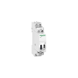
impulse relay iTLc - 1P - 1NO - 16A - coil 230...240 VAC 50/60Hz-

PLC Direct is not an authorized distributor. We offer a broad range of in-stock products with minimal lead time.
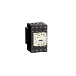
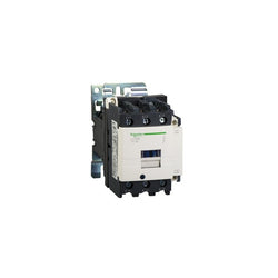
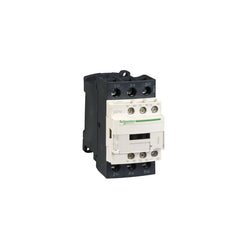
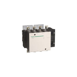
TeSys Deca contactor, 4 poles (4NO), 80A/690V AC-1, for non-inductive load applications. It provides a 220V DC coil with transient suppressor module, 1NO+1NC built-in auxiliary contacts (NC mirror certified), power connection by EverLink BTR screw terminals and control by screw clamp terminals. For operating rates until 3600 cycles/hour and environments until 60°C, it procures high reliability and durability. Compact (70mm width), DIN-rail mounting or screw fixing. Multi standards certified (IEC, UL, CSA, CCC, EAC, Marine), Green Premium compliant (RoHS/REACh).
Main
| Characteristic | Value(s) |
|---|---|
| Range | TeSys |
| Range of Product | TeSys Deca |
| Product or Component Type | Contactor |
| Device short name | LC1D |
| Contactor application | Resistive load |
| Utilisation category | AC-1 |
| Poles description | 4P |
| [Ue] rated operational voltage | Power circuit <= 690 V AC 25...400 Hz Power circuit <= 300 V DC |
| [Ie] rated operational current | 80 A (at <140 °F (60 °C)) at <= 440 V AC AC-1 for power circuit |
| [Uc] control circuit voltage | 220 V DC |
Complementary
| Characteristic | Value(s) |
|---|---|
| Compatibility code | LC1D |
| Pole contact composition | 4 NO |
| Protective cover | With |
| [Ith] conventional free air thermal current | 10 A (at 140 °F (60 °C)) for signalling circuit 80 A (at 140 °F (60 °C)) for power circuit |
| Irms rated making capacity | 140 A AC for signalling circuit conforming to IEC 60947-5-1 250 A DC for signalling circuit conforming to IEC 60947-5-1 1000 A at 440 V for power circuit conforming to IEC 60947 |
| Rated breaking capacity | 1000 A at 440 V for power circuit conforming to IEC 60947 |
| [Icw] rated short-time withstand current | 640 A 104 °F (40 °C) - 10 s for power circuit 900 A 104 °F (40 °C) - 1 s for power circuit 110 A 104 °F (40 °C) - 10 min for power circuit 260 A 104 °F (40 °C) - 1 min for power circuit 100 A - 1 s for signalling circuit 120 A - 500 ms for signalling circuit 140 A - 100 ms for signalling circuit |
| Associated fuse rating | 10 A gG for signalling circuit conforming to IEC 60947-5-1 125 A gG at <= 690 V coordination type 1 for power circuit 125 A gG at <= 690 V coordination type 2 for power circuit |
| Average impedance | 1.6 mOhm - Ith 80 A 50 Hz for power circuit |
| Power dissipation per pole | 10.2 W AC-1 |
| [Ui] rated insulation voltage | Power circuit 600 V CSA Power circuit 600 V UL Signalling circuit 690 V IEC 60947-1 Signalling circuit 600 V CSA Signalling circuit 600 V UL Power circuit 690 V IEC 60947-4-1 |
| Overvoltage category | III |
| pollution degree | 3 |
| [Uimp] rated impulse withstand voltage | 6 kV IEC 60947 |
| Safety reliability level | B10d = 1369863 cycles contactor with nominal load EN/ISO 13849-1 B10d = 20000000 cycles contactor with mechanical load EN/ISO 13849-1 |
| Mechanical durability | 10 Mcycles |
| Electrical durability | 0.5 Mcycles 80 A AC-1 <= 440 V |
| Control circuit type | DC standard |
| Coil technology | Built-in bidirectional peak limiting diode suppressor |
| Control circuit voltage limits | 0.1...0.3 Uc (-40â¦158 °F (-40â¦70 °C)):drop-out DC 0.75...1.25 Uc (-40â¦140 °F (-40â¦60 °C)):operational DC 1...1.25 Uc (140â¦158 °F (60â¦70 °C)):operational DC |
| Inrush power in W | 19 W 68 °F (20 °C)) |
| Hold-in power consumption in W | 7.4 W 68 °F (20 °C) |
| Operating time | 50 ±15 % ms closing 16...24 ms opening |
| Time constant | 34 ms |
| Connections - terminals | Control circuit: screw clamp terminals 2 0.002â¦0.004 in² (1â¦2.5 mm²) - cable stiffness: flexible with cable end Control circuit: screw clamp terminals 1 0.002â¦0.006 in² (1â¦4 mm²) - cable stiffness: flexible without cable end Control circuit: screw clamp terminals 2 0.002â¦0.006 in² (1â¦4 mm²) - cable stiffness: flexible without cable end Control circuit: screw clamp terminals 1 0.002â¦0.006 in² (1â¦4 mm²) - cable stiffness: flexible with cable end Control circuit: screw clamp terminals 1 0.002â¦0.006 in² (1â¦4 mm²) - cable stiffness: solid without cable end Control circuit: screw clamp terminals 2 0.002â¦0.006 in² (1â¦4 mm²) - cable stiffness: solid without cable end Power circuit: screw connection 1 0.002â¦0.05 in² (1â¦35 mm²) - cable stiffness: flexible without cable end Power circuit: screw connection 2 0.002â¦0.04 in² (1â¦25 mm²) - cable stiffness: flexible without cable end Power circuit: screw connection 1 0.002â¦0.05 in² (1â¦35 mm²) - cable stiffness: flexible with cable end Power circuit: screw connection 2 0.002â¦0.04 in² (1â¦25 mm²) - cable stiffness: flexible with cable end Power circuit: screw connection 1 0.002â¦0.05 in² (1â¦35 mm²) - cable stiffness: solid without cable end Power circuit: screw connection 2 0.002â¦0.04 in² (1â¦25 mm²) - cable stiffness: solid without cable end |
| Tightening torque | Control circuit 15.05 lbf.in (1.7 N.m) screw clamp terminals flat à 6 mm Control circuit 15.05 lbf.in (1.7 N.m) screw clamp terminals Philips No 2 Power circuit 70.8 lbf.in (8 N.m) screw clamp terminals 0.04â¦0.05 in² (25â¦35 mm²) hexagonal 0.2 in (4 mm) Power circuit 44.3 lbf.in (5 N.m) screw clamp terminals 0.002â¦0.04 in² (1â¦25 mm²) hexagonal 0.2 in (4 mm) |
| Auxiliary contact composition | 1 NO + 1 NC |
| Auxiliary contacts type | Mechanically linked 1 NO + 1 NC IEC 60947-5-1 Mirror contact 1 NC IEC 60947-4-1 |
| Signalling circuit frequency | 25...400 Hz |
| Minimum switching voltage | 17 V for signalling circuit |
| Minimum switching current | 5 mA for signalling circuit |
| Insulation resistance | > 10 MOhm for signalling circuit |
| Non-overlap time | 1.5 ms on de-energisation between NC and NO contact 1.5 ms on energisation between NC and NO contact |
| Mounting Support | Plate Rail |
Main
| Characteristic | Value(s) |
|---|---|
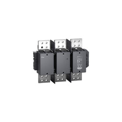
| Range | TeSys |
| Range of product | TeSys F |
| Product or component type | Contactor |
| Device short name | LC1F |
| Contactor application | Resistive load |
| Utilisation category | AC-1 |
| Poles description | 3P |
| [Ue] rated operational voltage | <= 1000 V AC 50/60 Hz <= 460 V DC |
| [Uc] control circuit voltage | 110 V DC |
| [Ie] rated operational current | 2100 A (at <40 °C) AC AC-1 |
Complementary
| Characteristic | Value(s) |
|---|---|
| [Uimp] rated impulse withstand voltage | 8 kV |
| [Ith] conventional free air thermal current | 2100 A (at 40 °C) |
| Rated breaking capacity | 3150 A conforming to IEC 60947-4-1 |
| [Icw] rated short-time withstand current | 10000 A 40 °C - 10 s 7500 A 40 °C - 30 s 5500 A 40 °C - 1 min 4200 A 40 °C - 3 min 3000 A 40 °C - 10 min |
| Associated fuse rating | 2000 A gG at <= 440 V |
| Average impedance | 0.1 mOhm - Ith 2100 A 50 Hz |
| [Ui] rated insulation voltage | 1000 V conforming to IEC 60947-4-1 1500 V conforming to VDE 0110 group C 1000 V conforming to UL 60947-4-1 |
| Power dissipation per pole | 200 W AC-1 |
| Overvoltage category | III |
| power pole contact composition | 3 NO |
| Control circuit voltage limits | Operational: 0.85...1.1 Uc (at 55 °C) Drop-out: 0.2...0.35 Uc (at 55 °C) |
| Inrush power in W | 2100 W (at 20 °C) |
| Hold-in power consumption in W | 10 W at 20 °C |
| Maximum operating rate | 600 cyc/h 55 °C |
| Operating time | 50...60 ms closing 45...60 ms opening |
| Connections - terminals | Control circuit: screw clamp terminals 1 cable(s) 1â¦4 mm²flexible without cable end Control circuit: screw clamp terminals 2 cable(s) 1â¦4 mm²flexible without cable end Control circuit: screw clamp terminals 1 cable(s) 1â¦4 mm²flexible with cable end Control circuit: screw clamp terminals 2 cable(s) 1â¦2.5 mm²flexible with cable end Control circuit: screw clamp terminals 1 cable(s) 1â¦4 mm²solid without cable end Control circuit: screw clamp terminals 2 cable(s) 1â¦4 mm²solid without cable end Power circuit: bar 4 cable(s) - busbar cross section: 100 x 5 mm Power circuit: bolted connection |
| Tightening torque | Control circuit: 1.2 N.m Power circuit: 58 N.m |
| Mounting support | Plate |
| Heat dissipation | 10 W |
| Standards | IEC 60947-1 IEC 60947-4-1 EN 60947-4-1 EN 60947-1 JIS C8201-4-1 UL 60947-4-1 CSA C22.2 No 60947-4-1 |
| Product certifications | UL CSA CCC CB Scheme EAC |
| Compatibility code | LC1F |
| Control circuit type | DC standard |

This Acti9 iPRD20r surge arrester protects 3P+N installations. it allows quick replacement of damaged cartridges. This Type 2 device is recommended for medium risk level and incoming panel board. It offers remote reporting of the "cartridge must be changed" message. It can be turned over to allow the phase/neutral/earth cables to enter through either the top or the bottom. The associated circuit breaker Isc breaking capacity can go up to 50kA. It is compatible with TT and TN-S earthing system. The Imax rated discharge current is up to 40kA. The In nominal discharge current is 15kA. The Uc maximum continuous operating voltage in differential mode (between phase and neutral) is 350VAC. The Uc maximum continuous operating voltage in common mode (between neutral and earth) is 260VAC. The Up maximum voltage protection level is 1.4kV in common mode and 1.2kV in differential mode. The Un rated service voltage is 230VAC or 400VAC. The operating frequency is 50Hz or 60Hz. The dimensions are (W) 72mm x (H) 85mm x (D) 69mm. The width in 9mm pitches is 8. The weight is 450g. The degree of protection is IP20 and IP40 in modular enclosure. The operating temperature is -25°C to +60°C. The storage temperature is -40°C to +85°C. This product is compliant with EN 61643-11 and IEC 61643-11 standard.
Main
| Characteristic | Value(s) |
|---|---|
| Range of product | IPRD |
| range of product | Acti9 |
| product name | Acti9 iPRD |
| Product or component type | Surge arrester with pluggable cartridge |
| Device short name | iPRD20r |
| Device application | Distribution |
| Standards | EN 61643-11:2012 IEC 61643-11:2011 |
| Product certifications | CE |
| Quality labels | NF KEMA-KEUR |
| Poles description | 3P + N |
| Remote signalling | With |
| Signal contacts composition | 1 SD (1 C/O) |
| Surge arrester type | Electrical distribution network |
| Earthing system | TT TN-S |
Complementary
| Characteristic | Value(s) |
|---|---|
| Surge arrester class type | Type 2 |
| Surge arrester technology | MOV + GDT |
| [Ue] rated operational voltage | 230/400 V AC (+/- 10 %) at 50/60 Hz |
| Nominal discharge current | Common mode: 5 kA (L/PE) Common mode: 5 kA (N/PE) Differential mode: 5 kA (L/N) |
| Maximum discharge current | Common mode: 20 kA L/PE Common mode: 20 kA N/PE Differential mode: 20 kA L/N |
| [Uc] maximum continuous operating voltage | Common mode: 260 V N/PE Differential mode: 350 V L/N |
| Maximum [Up] voltage protection level | Differential mode <1.2 kV type 2 L/N Common mode <1.4 kV type 2 N/PE |
| [Ut] temporary overvoltage | 337 V L/N 5 s withstand 1200 V N/PE 200 ms safe failure mode 442 V L/PE 5 s withstand 1455 V L/PE 200 ms safe failure mode |
| Disconnector device type | Associated circuit breaker IC60N 20 A curve C - Icu 10 kA Associated circuit breaker iC60H 20 A curve C - Icu 15 kA Associated circuit breaker iC60L 20 A curve C - Icu 25 kA Associated circuit breaker NG125H 20 A curve C - Icu 36 kA Associated circuit breaker NG125L 20 A curve C - Icu 50 kA Associated fuse gG 40 A - Icu 15 kA Associated fuse gG 80 A - Icu 50 kA |
| Signalling circuit voltage | 0.25 A/250 V AC 50/60 Hz |
| Mounting mode | Clip-on (DIN rail) |
| 9 mm pitches | 8 |
| Height | 85 mm |
| Width | 72 mm |
| Depth | 69 mm |
| Product weight | 450 g |
| Colour | White (RAL 9003) |
| [Ipe] Ground residual current | 0.003 mA 0.6 mA |
| Connections - terminals | Tunnel type terminal (top or bottom) 2.5â¦25 mm² rigid Tunnel type terminal (top or bottom) 4â¦16 mm² flexible Tunnel type terminal (top or bottom) 4â¦16 mm² flexible with ferrule |
| Wire stripping length | 14 mm |
| Tightening torque | 3.5 N.m |
| Compatibility code | IPRD20r |

TeSys GV direct rotary handle, replacement part for motor circuit breakers GV5P. For main switch usage, it provides a black handle on a black bezel with indication of 3 positions OFF, ON, TRIP. Equipped with a "push to trip" button. Padlockable in OFF position with up to 3 padlocks (to be ordered separately).
Main
| Characteristic | Value(s) |
|---|---|
| Range | TeSys |
| Product or Component Type | Rotary handle |
| Device short name | GV5AP |
| Range compatibility | TeSys TeSys GV5 motor circuit breaker |
| Accessory / separate part category | Control accessory |
| Handle colour | Black |
| Handle front plate colour | Black |
| Rotary handle mounting location | Front |
| Rotary handle mounting style | Direct |
Complementary
| Characteristic | Value(s) |
|---|---|
| Rotary handle padlocking | 1 to 3 padlocks 0.2â¦0.3 in (5â¦8 mm) Padlock in OFF position |
| Product Weight | 0.49 lb(US) (0.22 kg) |
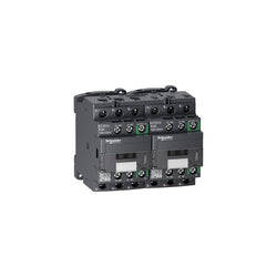
TeSys D reversing contactor - 3P - <= 440 V - 12 A AC-3 - 100...250 V AC/DC coil
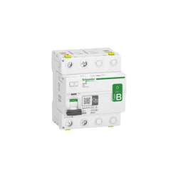
Acti9 iID - Residual Current Circuit Breaker -2P - 40A - 30mA - B-SI type
TeSys D contactor - 3P(3 NO) - AC-3 - <= 440 V 38 A - 72 V DC standard coil

Main
| Characteristic | Value(s) |
|---|---|
| Range | TeSys |
| Range of Product | TeSys F |
| Product or Component Type | Contactor |
| Device short name | LC1F |
| Contactor application | Resistive load |
| Utilisation category | AC-1 |
| Poles description | 3P |
| [Ue] rated operational voltage | <= 460 V DC <= 690 V AC 50/60 Hz |
| [Uc] control circuit voltage | 380 V AC 40...400 Hz |
| [Ie] rated operational current | 1260 A (at <104 °F (40 °C)) AC-1 |
Complementary
| Characteristic | Value(s) |
|---|---|
| [Uimp] rated impulse withstand voltage | 8 kV |
| [Ith] conventional free air thermal current | 1260 A (at 104 °F (40 °C)) |
| Rated breaking capacity | 1890 A conforming to IEC 60947-4-1 |
| [Icw] rated short-time withstand current | 3000 A 104 °F (40 °C) - 3 min 8000 A 104 °F (40 °C) - 10 s 5200 A 104 °F (40 °C) - 30 s 4000 A 104 °F (40 °C) - 1 min 2000 A 104 °F (40 °C) - 10 min |
| Associated fuse rating | 1000 A gG at <= 440 V |
| Average impedance | 0.12 mOhm - Ith 1260 A 50 Hz |
| [Ui] rated insulation voltage | 1000 V IEC 60947-4-1 1500 V VDE 0110 group C |
| Power dissipation per pole | 120 W AC-1 |
| Overvoltage category | III |
| power pole contact composition | 3 NO |
| Control circuit voltage limits | Operational 0.85...1.1 Uc 40...400 Hz 131 °F (55 °C)) Drop-out 0.25...0.5 Uc 40...400 Hz 131 °F (55 °C)) |
| Inrush power in VA | 1650 VA, 40...400 Hz 0.9 68 °F (20 °C)) |
| Hold-in power consumption in VA | 22 VA, 40...400 Hz 0.9 68 °F (20 °C)) |
| Maximum operating rate | 1200 cyc/h 131 °F (55 °C) |
| Operating time | 40...80 ms closing 100...200 ms opening |
| Connections - terminals | Control circuit screw clamp terminals 1 0.002â¦0.006 in² (1â¦4 mm²)flexible without cable end Control circuit screw clamp terminals 2 0.002â¦0.006 in² (1â¦4 mm²)flexible without cable end Control circuit screw clamp terminals 1 0.002â¦0.006 in² (1â¦4 mm²)flexible with cable end Control circuit screw clamp terminals 2 0.002â¦0.004 in² (1â¦2.5 mm²)flexible with cable end Control circuit screw clamp terminals 1 0.002â¦0.006 in² (1â¦4 mm²)solid without cable end Control circuit screw clamp terminals 2 0.002â¦0.006 in² (1â¦4 mm²)solid without cable end Power circuit bar 2 100 x 5 mm Power circuit bolted connection |
| Tightening torque | Control circuit 10.6 lbf.in (1.2 N.m) Power circuit 513.3 lbf.in (58 N.m) |
| Mounting Support | Plate |
| Heat dissipation | 20 W |
| Standards | IEC 60947-4-1 JIS C8201-4-1 IEC 60947-1 EN 60947-4-1 EN 60947-1 |
| Product Certifications | CB UL CSA CQC CE UKCA CCC |
| Compatibility code | LC1F |
| Control circuit type | AC 40...400 Hz |

residual current circuit breaker (RCCB), Acti9 iID40, 1P+N, 40 A, 300 mA, AC type
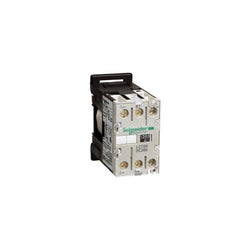
TeSys SK mini contactor - 2P (2 NO) - AC-3 - 690 V 5 A - 110 V AC coil
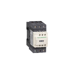
TeSys Deca contactor, 3 poles (3NO), for motor control applications up to 65A/440V AC-3/3e (30kW@400V). They can be used to create motor starters for almost any type of application. It provides a 115V 50/60Hz AC coil, 1NO+1NC built-in auxiliary contacts (NC mirror certified), power connection by EverLink BTR screw connectors, control connection by screw clamp terminals. For operating rates until 3600 cycles/hour and environments until 60°C, it procures high reliability and durability. Compact (55mm width), DIN-rail mounting or screw fixing. Contactor is rated for 20HP at 200 to 208VAC, 20HP at 240VAC, 40HP at 480VAC and 50HP at 600VAC three phase. Multi standards certified (IEC, UL, CSA, CCC, EAC, Marine). When used with a 480VAC up to 110A circuit breaker, this contactor can have a SCCR up to 100kA. When used with up to a 600VAC 125A Class J or CC fuse, this contactor can have a SCCR up to 100kA. Contactor is supplied with a 115 VAC 50/60 Hz coil. Contactor has one normally open and one normally closed auxiliary contact built-in as standard. The NC contact is mirror certified. Screw clamp terminals are used for load and auxiliary connections. An extensive line of accessories makes it easy to meet the requirements of most applications. The contactor is 4.80 inches tall, 2.17 inches wide and 4.72 inches deep. It weighs 1.90 lbs. Contactor is certified to UL, CSA, IEC, CCC, EAC and Marine standards.
Main
| Characteristic | Value(s) |
|---|---|
| Range | TeSys TeSys Deca |
| Range of Product | TeSys Deca |
| Product or Component Type | Contactor |
| Device short name | LC1D |
| Contactor application | Motor control Resistive load |
| Utilisation category | AC-4 AC-1 AC-3 AC-3e |
| Poles description | 3P |
| [Ue] rated operational voltage | Power circuit <= 690 V AC 25...400 Hz Power circuit <= 300 V DC |
| [Ie] rated operational current | 80 A (at <140 °F (60 °C)) at <= 440 V AC AC-1 for power circuit 65 A (at <140 °F (60 °C)) at <= 440 V AC AC-3 for power circuit 65 A (at <140 °F (60 °C)) at <= 440 V AC AC-3e for power circuit |
| [Uc] control circuit voltage | 115 V AC 50/60 Hz |
Complementary
| Characteristic | Value(s) |
|---|---|
| Motor power kW | 11 kW at 400 V AC 50/60 Hz (AC-4) 18.5 kW at 220...230 V AC 50/60 Hz (AC-3) 30 kW at 380...400 V AC 50/60 Hz (AC-3) 37 kW at 500 V AC 50/60 Hz (AC-3) 37 kW at 660...690 V AC 50/60 Hz (AC-3) 18.5 kW at 220...230 V AC 50/60 Hz (AC-3e) 30 kW at 380...400 V AC 50/60 Hz (AC-3e) 37 kW at 500 V AC 50/60 Hz (AC-3e) 37 kW at 660...690 V AC 50/60 Hz (AC-3e) |
| Maximum Horse Power Rating | 40 hp at 460/480 V AC 50/60 Hz for 3 phase motors 5 hp at 115 V AC 50/60 Hz for 1 phase motors 10 hp at 230/240 V AC 50/60 Hz for 1 phase motors 20 hp at 200/208 V AC 50/60 Hz for 3 phase motors 20 hp at 230/240 V AC 50/60 Hz for 3 phase motors 50 hp at 575/600 V AC 50/60 Hz for 3 phase motors |
| Compatibility code | LC1D |
| Pole contact composition | 3 NO |
| Protective cover | With |
| [Ith] conventional free air thermal current | 10 A (at 140 °F (60 °C)) for signalling circuit 80 A (at 140 °F (60 °C)) for power circuit |
| Irms rated making capacity | 140 A AC for signalling circuit conforming to IEC 60947-5-1 250 A DC for signalling circuit conforming to IEC 60947-5-1 1000 A at 440 V for power circuit conforming to IEC 60947 |
| Rated breaking capacity | 1000 A at 440 V for power circuit conforming to IEC 60947 |
| [Icw] rated short-time withstand current | 640 A 104 °F (40 °C) - 10 s for power circuit 900 A 104 °F (40 °C) - 1 s for power circuit 110 A 104 °F (40 °C) - 10 min for power circuit 260 A 104 °F (40 °C) - 1 min for power circuit 100 A - 1 s for signalling circuit 120 A - 500 ms for signalling circuit 140 A - 100 ms for signalling circuit |
| Associated fuse rating | 10 A gG for signalling circuit conforming to IEC 60947-5-1 125 A gG at <= 690 V coordination type 1 for power circuit 125 A gG at <= 690 V coordination type 2 for power circuit |
| Average impedance | 1.5 mOhm - Ith 80 A 50 Hz for power circuit |
| Power dissipation per pole | 9.6 W AC-1 6.3 W AC-3 6.3 W AC-3e |
| [Ui] rated insulation voltage | Power circuit 600 V CSA Power circuit 600 V UL Signalling circuit 690 V IEC 60947-1 Signalling circuit 600 V CSA Signalling circuit 600 V UL Power circuit 690 V IEC 60947-4-1 |
| Overvoltage category | III |
| pollution degree | 3 |
| [Uimp] rated impulse withstand voltage | 6 kV IEC 60947 |
| Safety reliability level | B10d = 1369863 cycles contactor with nominal load EN/ISO 13849-1 B10d = 20000000 cycles contactor with mechanical load EN/ISO 13849-1 |
| Mechanical durability | 6 Mcycles |
| Electrical durability | 1.4 Mcycles 80 A AC-1 <= 440 V 1.45 Mcycles 65 A AC-3 <= 440 V 1.45 Mcycles 65 A AC-3e <= 440 V |
| Control circuit type | AC 50/60 Hz standard |
| Coil technology | Without built-in suppressor module |
| Control circuit voltage limits | 0.3...0.6 Uc (-40â¦158 °F (-40â¦70 °C)):drop-out AC 50/60 Hz 0.8...1.1 Uc (-40â¦140 °F (-40â¦60 °C)):operational AC 50 Hz 0.85...1.1 Uc (-40â¦140 °F (-40â¦60 °C)):operational AC 60 Hz 1...1.1 Uc (140â¦158 °F (60â¦70 °C)):operational AC 50/60 Hz |
| Inrush power in VA | 140 VA 60 Hz cos phi 0.75 (at 68 °F (20 °C)) 160 VA 50 Hz cos phi 0.75 (at 68 °F (20 °C)) |
| Hold-in power consumption in VA | 13 VA 60 Hz cos phi 0.3 (at 68 °F (20 °C)) 15 VA 50 Hz cos phi 0.3 (at 68 °F (20 °C)) |
| Heat dissipation | 4â¦5 W at 50/60 Hz |
| Operating time | 4...19 ms opening 12...26 ms closing |
| Maximum operating rate | 3600 cyc/h at 60 °C |
| Connections - terminals | Control circuit: screw clamp terminals 2 0.002â¦0.004 in² (1â¦2.5 mm²) - cable stiffness: flexible with cable end Control circuit: screw clamp terminals 1 0.002â¦0.006 in² (1â¦4 mm²) - cable stiffness: flexible without cable end Control circuit: screw clamp terminals 2 0.002â¦0.006 in² (1â¦4 mm²) - cable stiffness: flexible without cable end Control circuit: screw clamp terminals 1 0.002â¦0.006 in² (1â¦4 mm²) - cable stiffness: flexible with cable end Control circuit: screw clamp terminals 1 0.002â¦0.006 in² (1â¦4 mm²) - cable stiffness: solid without cable end Control circuit: screw clamp terminals 2 0.002â¦0.006 in² (1â¦4 mm²) - cable stiffness: solid without cable end Power circuit: screw connection 1 0.002â¦0.05 in² (1â¦35 mm²) - cable stiffness: flexible without cable end Power circuit: screw connection 2 0.002â¦0.04 in² (1â¦25 mm²) - cable stiffness: flexible without cable end Power circuit: screw connection 1 0.002â¦0.05 in² (1â¦35 mm²) - cable stiffness: flexible with cable end Power circuit: screw connection 2 0.002â¦0.04 in² (1â¦25 mm²) - cable stiffness: flexible with cable end Power circuit: screw connection 1 0.002â¦0.05 in² (1â¦35 mm²) - cable stiffness: solid without cable end Power circuit: screw connection 2 0.002â¦0.04 in² (1â¦25 mm²) - cable stiffness: solid without cable end |
| Tightening torque | Control circuit 15.05 lbf.in (1.7 N.m) EverLink BTR screw connectors flat à 6 mm Control circuit 15.05 lbf.in (1.7 N.m) EverLink BTR screw connectors Philips No 2 Power circuit 70.8 lbf.in (8 N.m) EverLink BTR screw connectors 0.04â¦0.05 in² (25â¦35 mm²) hexagonal 0.2 in (4 mm) Power circuit 44.3 lbf.in (5 N.m) EverLink BTR screw connectors 0.002â¦0.04 in² (1â¦25 mm²) hexagonal 0.2 in (4 mm) Control circuit 15.05 lbf.in (1.7 N.m) EverLink BTR screw connectors pozidriv No 2 Power circuit 22.1 lbf.in (2.5 N.m) EverLink BTR screw connectors pozidriv No 2 |
| Auxiliary contact composition | 1 NO + 1 NC |
| Auxiliary contacts type | Mechanically linked 1 NO + 1 NC IEC 60947-5-1 Mirror contact 1 NC IEC 60947-4-1 |
| Signalling circuit frequency | 25...400 Hz |
| Minimum switching voltage | 17 V for signalling circuit |
| Minimum switching current | 5 mA for signalling circuit |
| Insulation resistance | > 10 MOhm for signalling circuit |
| Non-overlap time | 1.5 ms on de-energisation between NC and NO contact 1.5 ms on energisation between NC and NO contact |
| Mounting Support | Plate Rail |
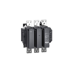
TeSys F contactor - 3P (3 NO) - AC-3 - <= 440 V 185 A - coil 110 V DC. Comes without coil.

This Acti9 iC40N product is a low voltage miniature circuit breaker (MCB). It is a 1P+N circuit breaker with 1 protected pole and 20A In rated current and B tripping curve. The rated short circuit breaking capacity goes up to 10kA at 230VAC conforming to EN/IEC 60947-2 standard and 6000A at 230VAC conforming to EN/IEC 60898-1 standard. This product complies with both industrial standard EN/IEC 60898-1 and residential standard EN/IEC 60947-2. This miniature circuit breaker combines functions of circuit protection against short circuit and overload current, control and isolation. The installation and cabling are simplified with clip on function as well as ease of maintenance. It has an electrical endurance going up to 20000 cycles and a mechanical endurance going up to 20000 cycles. The Ue operational voltage is 230VAC. The Ui rated insulation voltage is 400VAC. The Uimp rated impulse withstand voltage is 4kV. The operating frequency is 50Hz or 60Hz. It can be mounted on DIN rail for modular installation. Its width is 2 pitches of 9mm. Pollution degree is 3. The product colour is white (RAL9003). The dimensions are (W) 18mm x (H) 85mm x (D) 74mm. The weight is 120g. According to IEC 60529 standard, the degree of protection is IP20 and IP40 in enclosure. The operating temperature is -25°C to 70°C. The storage temperature is -40°C to 85°C.
Main
| Characteristic | Value(s) |
|---|---|
| Range | Acti9 |
| product name | Acti9 iC40 |
| Product or component type | Miniature circuit-breaker |
| Device short name | iC40N |
| Device application | Distribution |
| Poles description | 1P + N |
| Number of protected poles | 1 |
| Neutral position | Left |
| [In] rated current | 20 A |
| Network type | AC |
| Trip unit technology | Thermal-magnetic |
| Curve code | B |
| Breaking capacity | 10 kA Icu at 230 V AC 50/60 Hz conforming to EN/IEC 60947-2 6000 A Icn at 230 V AC 50/60 Hz conforming to EN/IEC 60898-1 |
| Suitability for isolation | Yes conforming to EN/IEC 60947-2 |
| Quality labels | KEMA IMQ OVE |
Complementary
| Characteristic | Value(s) |
|---|---|
| Network frequency | 50/60 Hz |
| [Ue] rated operational voltage | 230 V AC 50/60 Hz |
| Magnetic tripping limit | 3...5 x In conforming to EN/IEC 60898-1 4 x In +/- 20 % conforming to EN/IEC 60947-2 |
| [Ics] rated service breaking capacity | 6000 A 100 % x Icn at 230 V AC 50/60 Hz conforming to EN/IEC 60898-1 7.5 kA 75 % x Icn at 230 V AC 50/60 Hz conforming to EN/IEC 60947-2 |
| Limitation class | 3 conforming to EN/IEC 60898-1 |
| [Ui] rated insulation voltage | 400 V AC 50/60 Hz conforming to EN/IEC 60947-2 |
| [Uimp] rated impulse withstand voltage | 4 kV conforming to EN/IEC 60947-2 |
| Contact position indicator | Yes |
| control type | Toggle |
| Local signalling | ON/OFF indication Trip indicator |
| Mounting mode | Clip-on |
| Mounting support | DIN rail |
| 9 mm pitches | 2 |
| Height | 85 mm |
| Width | 18 mm |
| Depth | 74 mm |
| Product weight | 120 g |
| Colour | White |
| Mechanical durability | 20000 cycles |
| Electrical durability | 20000 cycles |
| Locking options description | Padlocking device |
| Connections - terminals | Tunnel type terminals top or bottom 1â¦10 mm² flexible Tunnel type terminals top or bottom 1â¦16 mm² rigid |
| Wire stripping length | 14 mm for top or bottom connection |
| Tightening torque | 2 N.m top or bottom |
| Earth-leakage protection | Separate block |
TeSys F contactor-4P(4 NO)-AC-1 <= 440V 400A with coil LX1/LX9 -241000V AC 40/400Hz, LX4 -24...460V DC, LXE -100...250V AC 50/60Hz or 100380V DC