
 1 year warranty

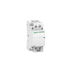
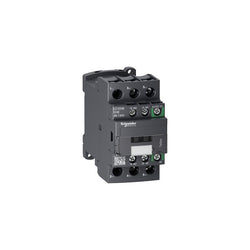
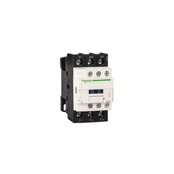
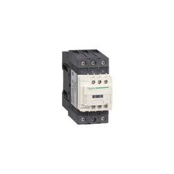
This Acti9 iCT is a modular contactor. It is a 2P remote control device with 2 normally open contacts. The rated current is 63A for AC-7a and 20A for AC-7b. The Ue rated operational voltage is 250VAC. The Uc control voltage is 24VAC. This device could be used for control circuits. This device could be used for remote switching lighting loads, small motors (fans, mixers) or HVAC system applications. It is compatible with all the Acti9 control auxiliaries, for lighting, heating & ventilation control applications. This product is compliant with IEC/EN 61095. Electrical endurance goes up to 100000 cycles for AC-7A or AC-1, 30000 cycles for AC-7C, AC-7B, AC-3, AC-5A or AC-5B The maximum switching operations is 6 per minute. The Ui rated insulation voltage is 500VAC. The Uimp rated impulse withstand voltage is 4kV. Pollution degree is 2. It is DIN rail mountable. Its width is 4 pitches of 9mm. The product color is white (RAL9003). The dimensions are (W) 85mm x (H) 36mm x (D) 68.5mm. According to IEC 60529 standard, the degree of protection is IP20 and IP40 in enclosure. The operating temperature is from -5°C to 60 °C. The storage temperature is from -40°C to 70°C.
Main
| Characteristic | Value(s) |
|---|---|
| range of product | Acti9 |
| product name | Acti9 iCT |
| Product or component type | Contactor |
| Device short name | iCT |
| Device application | Motor-heating-lighting |
| Poles | 2P |
| [Ie] rated operational current | 63 A AC-7A 20 A AC-7B |
| Pole contact composition | 2 NO |
| Network type | AC |
| control type | Remote control |
| [Uc] control circuit voltage | 24 V AC 50 Hz |
Complementary
| Characteristic | Value(s) |
|---|---|
| Network frequency | 50 Hz |
| [Ue] rated operational voltage | 250 V AC 50 Hz |
| Maximum power | 1.6 W at 250 V AC |
| [Ui] rated insulation voltage | 500 V AC 50/60 Hz |
| [Uimp] rated impulse withstand voltage | 4 kV |
| Control signal type | Maintained |
| Switching frequency | 100 switching operations/day |
| Local signalling | Action indicator |
| Hold-in power consumption in VA | 4.6 VA |
| Inrush power in VA | 34 VA |
| Mounting mode | Clip-on |
| Mounting support | 35 mm symmetrical DIN rail |
| 9 mm pitches | 4 |
| Height | 85 mm |
| Width | 36 mm |
| Depth | 68.5 mm |
| Colour | White |
| Mechanical durability | 1000000 cycles |
| Electrical durability | 100000 cycles IEC/EN 61095 63 A 50 Hz AC-7A 30000 cycles IEC/EN 61095 20 A 50 Hz AC-7B 30000 cycles IEC/EN 61095 50 Hz AC-7C 100000 cycles EN/IEC 60947-4-1 50 Hz AC-1 30000 cycles EN/IEC 60947-4-1 50 Hz AC-3 30000 cycles EN/IEC 60947-4-1 50 Hz AC-5a 30000 cycles EN/IEC 60947-4-1 50 Hz AC-5b |
| Connections - terminals | Control circuit: tunnel type terminals2 cable(s) 1.5 mm² rigid Control circuit: tunnel type terminals1 cable(s) 1.5â¦2.5 mm² rigid Power circuit: tunnel type terminals1 cable(s) 6â¦16 mm² flexible Power circuit: tunnel type terminals1 cable(s) 6â¦25 mm² rigid Control circuit: tunnel type terminals2 cable(s) 1.5â¦2.5 mm² flexible |
| Tightening torque | Control circuit: 0.8 N.m Power circuit: 3.5 N.m |
| Product compatibility | IACTc IACTs IATEt IACTp |
| Compatibility code | ICT |
| Market segment | Residential Small commercial |

PLC Direct is not an authorized distributor. We offer a broad range of in-stock products with minimal lead time.

Motor circuit breaker, TeSys GV6, 3P, 320A, Icu 70kA, thermal magnetic
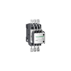
TeSys Deca contactor, 3 poles (3NO), for switching 3-phase capacitor banks up to 20kVAR@400V 50Hz (33kVAR@690V). It provides a 400V 50/60Hz AC coil, 1NO+2NC instantaneous auxiliary contacts, with front mounted early make poles and pre-wired damping resistors for current limitation. For operating rates until 240 cycles/hour and environments until 60°C, it procures high reliability and durability. Compact (45mm width), DIN-rail mounting or screw fixing. Certified IEC 60947 and compliant with shunt capacitors standard IEC 60831, Green Premium product (RoHS/REACh).
Main
| Characteristic | Value(s) |
|---|---|
| Range | TeSys |
| product name | TeSys LC1D.K TeSys Deca |
| Product or Component Type | Capacitor duty contactor |
| Device short name | LC1DLK |
| Device Application | Control |
| Contactor application | Power factor correction |
| Utilisation category | AC-6b |
| Poles description | 3P |
| power pole contact composition | 3 NO |
| Device location in system | Inside delta interruption Line interruption |
| [Ue] rated operational voltage | Power circuit 690 V AC 50/60 Hz |
| Reactive power rating | 11 kvar 230 V AC 50 Hz 140 °F (60 °C) 20 kvar 400 V AC 50 Hz 140 °F (60 °C) 21 kvar 440 V AC 50 Hz 140 °F (60 °C) 33 kvar 690 V AC 50 Hz 140 °F (60 °C) |
| Control circuit type | AC 50/60 Hz |
| [Uc] control circuit voltage | 400 V AC 50/60 Hz |
| Auxiliary contact composition | 1 NO + 2 NC instantaneous |
| Electrical durability | 300000 cycles 400 V 200000 cycles 690 V |
| Mounting Support | DIN rail Plate |
| Standards | EN/IEC 60947-1 EN/IEC 60947-4-1 |
| Product Certifications | IECEE CB Scheme |
| Connections - terminals | Control circuit: screw clamp terminals 1 0.002â¦0.006 in² (1â¦4 mm²) - cable stiffness: solid Control circuit: screw clamp terminals 2 0.002â¦0.006 in² (1â¦4 mm²) - cable stiffness: solid Control circuit: screw clamp terminals 1 0.002â¦0.006 in² (1â¦4 mm²) - cable stiffness: flexible without cable end Control circuit: screw clamp terminals 2 0.002â¦0.006 in² (1â¦4 mm²) - cable stiffness: flexible without cable end Control circuit: screw clamp terminals 1 0.002â¦0.006 in² (1â¦4 mm²) - cable stiffness: flexible with cable end Control circuit: screw clamp terminals 2 0.002â¦0.004 in² (1â¦2.5 mm²) - cable stiffness: flexible with cable end Power circuit: screw clamp terminals 1 0.004â¦0.02 in² (2.5â¦16 mm²) - cable stiffness: solid Power circuit: screw clamp terminals 2 0.004â¦0.009 in² (2.5â¦6 mm²) - cable stiffness: solid Power circuit: screw clamp terminals 1 0.002â¦0.02 in² (1.5â¦10 mm²) - cable stiffness: flexible without cable end Power circuit: screw clamp terminals 2 0.002â¦0.009 in² (1.5â¦6 mm²) - cable stiffness: flexible without cable end Power circuit: screw clamp terminals 1 0.002â¦0.02 in² (1â¦10 mm²) - cable stiffness: flexible with cable end Power circuit: screw clamp terminals 2 0.002â¦0.006 in² (1â¦4 mm²) - cable stiffness: flexible with cable end |
| Tightening torque | Control circuit 15.05 lbf.in (1.7 N.m) screw clamp terminals Power circuit 22.1 lbf.in (2.5 N.m) screw clamp terminals |
| Maximum operating rate | 240 cyc/h |
Complementary
| Characteristic | Value(s) |
|---|---|
| Auxiliary contacts type | Mechanically linked 1 NO + 2 NC IEC 60947-5-1 |

This Acti9 iQuick PRD20r surge arrester protects 3P+N residential and larger buildings installations against indirect transient overvoltages. This Type 2 device autoprotected by an integrated circuit-breaker is recommanded for moderate risk level in incoming panel board. It offers remote reporting of the "cartridge must be changed" message. This prewired surge arrester allows quick replacement of withdrawable cartridges when they are damaged. It incorporates its end of life safety disconnector. The Isc integrated breaking capacity is 25kA. This Acti9 iQuick PRD20r is compatible with TT and TN-S earthing system. The Imax maximum discharge current is 20kA. The In nominal discharge current is 5kA. The Uc maximum continuous operating voltage in differential mode (between phase and neutral) is 350VAC. The Uc maximum continuous operating voltage in common mode is 264VAC between neutral and earth, and is 350VAC between phase and earth. The Up Voltage protection level in differential mode (between phase and neutral) is below or equal to 1.5kV. The Up Voltage protection level in common mode is below or equal to 1.5kV between phase and earth, or neutral and earth. The Un rated service voltage is 230VAC or 400VAC. The operating frequency is 50Hz or 60Hz. The dimensions are (W) 131.5mm x (H) 103.8mm x (D) 75.9mm. The width in 9mm pitches is 15. The weight is 810g. The degree of protection is IP20 and IP40 in modular enclosure. The operating temperature is -25°C to +60°C. The storage temperature is -40°C to +85°C. This product complies with IEC/EN 60947-5-1 and EN 61643-11: 2012 and IEC 61643-11: 2011 Type 2 standards.
Main
| Characteristic | Value(s) |
|---|---|
| Range of product | IQuick PRD |
| range of product | Acti9 |
| product name | Acti9 iQuick PRD |
| Product or component type | Surge arrester with pluggable cartridge |
| Device short name | iQuick PRD20r |
| Device application | Distribution |
| Standards | EN 61643-11:2012 IEC 61643-11:2011 |
| Product certifications | CE |
| Quality labels | KEMA-KEUR NF |
| Poles description | 3P + N |
| Remote signalling | With |
| Signal contacts composition | 1 SD (1 C/O) |
| Surge arrester type | Electrical distribution network |
| Earthing system | TT TN-S |
Complementary
| Characteristic | Value(s) |
|---|---|
| Surge arrester class type | Type 2 |
| Surge arrester technology | MOV + GDT |
| [Ue] rated operational voltage | 230/400 V AC (+/- 10 %) at 50/60 Hz |
| Nominal discharge current | Common mode: 5 kA (L/PE) Common mode: 5 kA (N/PE) Differential mode: 5 kA (L/N) |
| Maximum discharge current | Common mode: 20 kA L/PE Common mode: 20 kA N/PE Differential mode: 20 kA L/N |
| [Uc] maximum continuous operating voltage | Common mode: 264 V N/PE Common mode: 350 V L/PE Differential mode: 350 V L/N |
| Maximum [Up] voltage protection level | Common mode <1.5 kV type 2 L/PE Common mode <1.5 kV type 2 N/PE Differential mode <1.5 kV type 2 L/N |
| Disconnector device type | Integrated circuit breaker - Icu 25 kA |
| Signalling circuit voltage | 2 A/250 V AC 50/60 Hz |
| Mounting mode | Clip-on (DIN rail) |
| 9 mm pitches | 14.6 |
| Height | 94 mm |
| Width | 131.5 mm |
| Depth | 75.9 mm |
| Product weight | 0.84 kg |
| Colour | White (RAL 9003) |
| Connections - terminals | Tunnel type terminal (downside) 2.5â¦25 mm² Tunnel type terminal (upside) 2.5â¦25 mm² |
| Tightening torque | 2.5 N.m |
| Compatibility code | IQuick PRD20r |
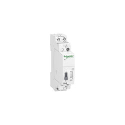
This Acti9 iTL is a modular impulse relay. This 2P device has 2 normally open contacts. Rated current is 16A, 24VAC to 250VAC operating voltage and it operates with 230VAC to 240VAC or 110VDC control voltage. Electrical endurance goes up to 200000 cycles for AC-21 or 100000 cycles for AC-22. The switching frequency is 5 switching operations/minute or 100 switching operations/day. The duration of the command order should be between 50ms to 1s. It is mainly used for lighting control applications. The Ui rated insulation voltage is 440VAC. The Uimp rated impulse withstand voltage is 6kV. The operating frequency is 50Hz or 60Hz. It is DIN rail mountable. Pollution degree is 3. Overvoltage category is IV. The dimensions are (W) 18mm x (H) 84mm x (D) 60mm. The degree of protection is IP20 and IP40 in an enclosure. The operating temperature is from -20°C to 50°C. The storage temperature is from -40°C to 70°C. This product is compliant with IEC/EN 60669-1 and IEC/EN 60669-2-2 standard.
Main
| Characteristic | Value(s) |
|---|---|
| range of product | Acti9 |
| product name | Acti9 iTL |
| Product or component type | Impulse relay |
| Device short name | iTL |
| Device application | Standard |
| Poles | 2P |
| Pole contact composition | 2 NO |
| [In] rated current | 16 A |
| Network type | AC |
| [Uc] control circuit voltage | 230...240 V AC 50/60 Hz 110 V DC |
Complementary
| Characteristic | Value(s) |
|---|---|
| Network frequency | 50/60 Hz |
| [Ue] rated operational voltage | 250 V AC 50/60 Hz |
| control type | Remote and manual control Coil deconnection |
| Control signal type | Impulse |
| Switching frequency | 5 switching operations/minute 100 switching operations/day |
| Impulse duration | 50 ms...1 s |
| Remote control type | Illuminated push-button 3 mA |
| Local signalling | ON/OFF indication |
| Mounting mode | Fixed |
| Mounting support | DIN rail |
| 9 mm pitches | 2 |
| Height | 84 mm |
| Width | 18 mm |
| Depth | 60 mm |
| Electrical durability | AC-21: 200000 cycles AC-22: 100000 cycles |
| Connections - terminals | Control circuit: tunnel type terminals 1 cable(s) 0.5â¦4 mm² rigid Control circuit: tunnel type terminals 1 cable(s) 0.5â¦4 mm² rigid with cable end Control circuit: tunnel type terminals 1 cable(s) 1â¦4 mm² flexible Control circuit: tunnel type terminals 1 cable(s) 1â¦4 mm² flexible with ferrule Power circuit: tunnel type terminals 1 cable(s) 1.5â¦4 mm² rigid Power circuit: tunnel type terminals 1 cable(s) 1.5â¦4 mm² rigid with cable end Power circuit: tunnel type terminals 1 cable(s) 1.5â¦4 mm² flexible Power circuit: tunnel type terminals 1 cable(s) 1.5â¦4 mm² flexible with ferrule |
| Wire stripping length | 11 mm |
| Tightening torque | 1 N.m |
| Range compatibility | Acti9 iATEt Acti9 iATL4 Acti9 iATLc Acti9 iATLc+s Acti9 iATLm Acti9 iATLs Acti9 iATLz Acti9 iETL iTL 16 Acti9 iATLc+c Acti9 iATL24 |
TeSys K contactor - 3P - AC-3 -= 440 V 9 A - 1 NO aux. - 48 V DC coil
TeSys D contactor 3P 38A AC-3 up to 440V coil 48-130V AC/DC
TeSys F contactor, 4 poles (4NO), 250A/690V AC-1, for non-inductive load applications. It provides a low sealed consumption 230V 40-400Hz AC coil, bolt terminals for bars or cables with lugs. For high operating rates until 2400 cycles/hour and environments until 55°C, it procures high reliability and durability. It makes installation and maintenance easy thanks to its drawer-mounted coil and a large choice of add-on blocks and accessories (to be ordered separately). Multi standards certified (IEC, UL, CSA, CCC, EAC, Marine), Green Premium compliant (RoHS/REACh).
Main
| Characteristic | Value(s) |
|---|---|
| Range | TeSys |
| Range of product | TeSys F |
| Product or component type | Contactor |
| Device short name | LC1F |
| Contactor application | Resistive load |
| Utilisation category | AC-1 |
| Poles description | 4P |
| [Ue] rated operational voltage | <= 690 V AC 50/60 Hz <= 460 V DC |
| [Uc] control circuit voltage | 230 V AC 40...400 Hz |
| [Ie] rated operational current | 250 A (at <40 °C) at <= 440 V AC-1 |
Complementary
| Characteristic | Value(s) |
|---|---|
| [Uimp] rated impulse withstand voltage | 8 kV |
| [Ith] conventional free air thermal current | 250 A (at 40 °C) |
| Rated breaking capacity | 1200 A conforming to IEC 60947-4-1 |
| [Icw] rated short-time withstand current | 1200 A 40 °C - 10 s 700 A 40 °C - 30 s 600 A 40 °C - 1 min 450 A 40 °C - 3 min 350 A 40 °C - 10 min |
| Associated fuse rating | 160 A aM at <= 440 V 250 A gG at <= 440 V |
| Average impedance | 0.35 mOhm - Ith 250 A 50 Hz |
| [Ui] rated insulation voltage | 1000 V conforming to IEC 60947-4-1 1500 V conforming to VDE 0110 group C |
| Power dissipation per pole | 22 W AC-1 |
| Overvoltage category | III |
| power pole contact composition | 4 NO |
| Control circuit voltage limits | Operational: 0.85...1.1 Uc 40...400 Hz (at 55 °C) Drop-out: 0.2...0.55 Uc 40...400 Hz (at 55 °C) |
| Mechanical durability | 10 Mcycles |
| Inrush power in VA | 770 VA, 40...400 Hz cos phi 0.9 (at 20 °C) |
| Hold-in power consumption in VA | 8.1 VA, 40...400 Hz cos phi 0.9 (at 20 °C) |
| Maximum operating rate | 2400 cyc/h 55 °C |
| Operating time | 35 ms closing (at Uc) 130 ms opening (at Uc) |
| Connections - terminals | Control circuit: screw clamp terminals 1 cable(s) 1â¦4 mm²flexible without cable end Control circuit: screw clamp terminals 2 cable(s) 1â¦4 mm²flexible without cable end Control circuit: screw clamp terminals 1 cable(s) 1â¦4 mm²flexible with cable end Control circuit: screw clamp terminals 2 cable(s) 1â¦2.5 mm²flexible with cable end Control circuit: screw clamp terminals 1 cable(s) 1â¦4 mm²solid without cable end Control circuit: screw clamp terminals 2 cable(s) 1â¦4 mm²solid without cable end Power circuit: bar 2 cable(s) - busbar cross section: 25 x 3 mm Power circuit: lugs-ring terminals 1 cable(s) 120 mm² Power circuit: connector 1 cable(s) 120 mm² Power circuit: bolted connection |
| Tightening torque | Control circuit: 1.2 N.m Power circuit: 18 N.m |
| Mounting support | Plate |
| Heat dissipation | 5.9â¦7.2 W |
| Standards | IEC 60947-4-1 IEC 60947-1 EN 60947-1 EN 60947-4-1 JIS C8201-4-1 |
| Product certifications | LROS (Lloyds register of shipping) RMRoS CCC DNV CB RINA UL ABS BV UKCA |
| Compatibility code | LC1F |
| Control circuit type | AC at 40...400 Hz |
TeSys D contactor - 4P(2 NO + 2 NC) - AC-1 - <= 440 V 60 A - 24 V DC coil

This Acti9 accessory is a plug in base for modular products. This accessory is compatible the Acti9 products like Acti9 iC60, Acti9 iID, Acti9 iSW and Acti9 iSW-NA. It is dedicated for 1 pole. The dimensions are (W) 19mm x (H) 177mm x (D) 70mm.
Main
| Characteristic | Value(s) |
|---|---|
| Product or component type | Plug-in base |
| Device short name | plug-in base |
| Accessory / separate part category | Installation accessory |
| Colour | White |
Complementary
| Characteristic | Value(s) |
|---|---|
| Poles description | 1P |
| Mounting mode | Clip-on |
| Quantity per set | 1 |
| Height | 177 mm |
| Width | 19 mm |
| Depth | 70 mm |
PLC Direct is not an authorized distributor. We offer a broad range of in-stock products with minimal lead time.
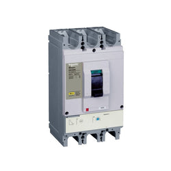
NSC630K ETS2.3 630A Circuit Breaker - 3P/3d
TeSys D contactor - 3P(3 NO) - AC-3 - <= 440 V 32 A - 48 V AC coil
TeSys K contactor - 4P (4 NO) - AC-1 <= 440 V 20 A - 220...230 V AC coil


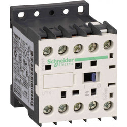
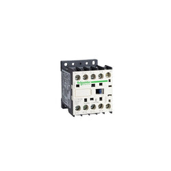
LP1K0910BD is a compact 3-pole TeSys K contactor from Schneider Electric for motor applications. Rated 9A AC-3 4kW@400V, it includes a 24V DC coil and 1NO auxiliary contact allowing easy integration to all control systems. LP1K0910BD is a 3-pole TeSys K contactor from Schneider Electric for simple motor applications rated up to 4kW@400V. Very compact, DIN-rail compatible, with connections by screw clamp terminals, it can be easily integrated into all control systems thanks to its 24V DC coil and 1NO built-in auxiliary contact. Available worldwide, it complies with multi-standards (IEC, UL, CSA, CCC, EAC, Marine). Very compact, 45mm wide, for DIN-rail and panel mounting. Ready for connection to all control systems thanks to a 24V DC control voltage and 1NO built-in auxiliary contact. Optimized for simple power applications. Can be completed with auxiliary contact blocks (LA1K, LA2K) and thermal relays (LR2K).
Main
| Characteristic | Value(s) |
|---|---|
| Range | TeSys |
| Product or Component Type | Contactor |
| Device short name | LP1K |
| Contactor application | Motor control Resistive load |
Complementary
| Characteristic | Value(s) |
|---|---|
| Utilisation category | AC-3 AC-3e AC-1 AC-4 |
| Poles description | 3P |
| power pole contact composition | 3 NO |
| [Ue] rated operational voltage | Power circuit <= 690 V AC <= 400 Hz Signalling circuit <= 690 V AC <= 400 Hz |
| [Ie] rated operational current | 9 A (at <140 °F (60 °C)) at <= 440 V AC AC-3 for power circuit 9 A (at <140 °F (60 °C)) at <= 440 V AC AC-3e for power circuit 20 A (at <140 °F (60 °C)) at <= 690 V AC AC-1 for power circuit |
| Control circuit type | DC standard |
| [Uc] control circuit voltage | 24 V DC |
| Motor power kW | 2.2 kW 220...230 V AC 50/60 Hz AC-3 4 kW 380...415 V AC 50/60 Hz AC-3 4 kW 440/690 V AC 50/60 Hz AC-3 2.2 kW 220...230 V AC 50/60 Hz AC-3e 4 kW 380...415 V AC 50/60 Hz AC-3e 4 kW 440/690 V AC 50/60 Hz AC-3e 2.2 kW 220...230 V AC 50/60 Hz AC-4 4 kW 380...415 V AC 50/60 Hz AC-4 4 kW 440/690 V AC 50/60 Hz AC-4 |
| Auxiliary contact composition | 1 NO |
| [Uimp] rated impulse withstand voltage | 8 kV |
| Overvoltage category | III |
| [Ith] conventional free air thermal current | 20 A (at 140 °F (60 °C)) for power circuit 10 A (at 122 °F (50 °C)) for signalling circuit |
| Irms rated making capacity | 110 A AC for power circuit conforming to IEC 60947 110 A AC for signalling circuit conforming to IEC 60947 |
| Rated breaking capacity | 110 A at 220...230 V conforming to IEC 60947 110 A at 380...400 V conforming to IEC 60947 110 A at 415 V conforming to IEC 60947 110 A at 440 V conforming to IEC 60947 80 A at 500 V conforming to IEC 60947 70 A at 660...690 V conforming to IEC 60947 |
| [Icw] rated short-time withstand current | 90 A 122 °F (50 °C) - 1 s for power circuit 85 A 122 °F (50 °C) - 5 s for power circuit 80 A 122 °F (50 °C) - 10 s for power circuit 60 A 122 °F (50 °C) - 30 s for power circuit 45 A 122 °F (50 °C) - 1 min for power circuit 40 A 122 °F (50 °C) - 3 min for power circuit 20 A 122 °F (50 °C) - >= 15 min for power circuit 80 A - 1 s for signalling circuit 90 A - 500 ms for signalling circuit 110 A - 100 ms for signalling circuit |
| Associated fuse rating | 25 A gG at <= 440 V for power circuit 25 A aM for power circuit 10 A gG for signalling circuit conforming to IEC 60947 10 A gG for signalling circuit conforming to VDE 0660 |
| Average impedance | 3 mOhm - Ith 20 A 50 Hz for power circuit |
| [Ui] rated insulation voltage | Power circuit 600 V UL 508 Power circuit 690 V IEC 60947-4-1 Signalling circuit 690 V IEC 60947-4-1 Signalling circuit 690 V IEC 60947-5-1 Signalling circuit 600 V UL 508 Power circuit 600 V CSA C22.2 No 14 Signalling circuit 600 V CSA C22.2 No 14 |
| Insulation resistance | > 10 MOhm for signalling circuit |
| Inrush power in W | 3 W 68 °F (20 °C)) |
| Hold-in power consumption in W | 3 W 68 °F (20 °C) |
| Heat dissipation | 1.3 W |
| Control circuit voltage limits | Operational: 0.8...1.15 Uc (at <122 °F (50 °C)) Drop-out: >= 0.10 Uc (at <122 °F (50 °C)) |
| Connections - terminals | screw clamp terminals 1 0.002â¦0.006 in² (1.5â¦4 mm²)solid screw clamp terminals 1 0.001â¦0.006 in² (0.75â¦4 mm²)flexible without cable end screw clamp terminals 1 0.0005â¦0.004 in² (0.34â¦2.5 mm²)flexible with cable end screw clamp terminals 2 0.002â¦0.006 in² (1.5â¦4 mm²)solid screw clamp terminals 2 0.001â¦0.006 in² (0.75â¦4 mm²)flexible without cable end screw clamp terminals 2 0.0005â¦0.002 in² (0.34â¦1.5 mm²)flexible with cable end Power circuit screw clamp terminals 2 0.002 in² (1.5 mm²)flexible with cable end |
| Maximum operating rate | 3600 cyc/h |
| Auxiliary contacts type | Instantaneous 1 NO |
| Minimum switching current | 5 mA for signalling circuit |
| Minimum switching voltage | 17 V for signalling circuit |
| Mounting Support | Rail Plate |
| Tightening torque | 7.08â¦11.5 lbf.in (0.8â¦1.3 N.m) screw clamp terminals Philips No 2 7.08â¦11.5 lbf.in (0.8â¦1.3 N.m) screw clamp terminals flat à 6 mm 7.08â¦11.5 lbf.in (0.8â¦1.3 N.m) screw clamp terminals pozidriv No 2 |
| Operating time | 30...40 ms coil energisation and NO closing 10 ms coil de-energisation and NO opening |
| Safety reliability level | B10d = 1369863 cycles contactor with nominal load EN/ISO 13849-1 B10d = 20000000 cycles contactor with mechanical load EN/ISO 13849-1 |
| Mechanical durability | 10 Mcycles |
| Electrical durability | 1.3 Mcycles 9 A AC-3 <= 440 V 1.3 Mcycles 9 A AC-3e <= 440 V 0.16 Mcycles 20 A AC-1 <= 690 V 0.02 Mcycles 54 A AC-4 <= 440 V |
| Height | 2.3 in (58 mm) |
| Width | 1.8 in (45 mm) |
| Depth | 2.2 in (57 mm) |
| Product Weight | 0.496 lb(US) (0.225 kg) |
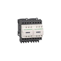
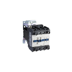
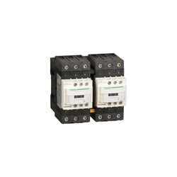
TeSys Deca changeover contactor, 4 poles (4NO), for non-inductive load applications up to 32A/690V AC-1. It provides 230V 50/60Hz AC coils, 2NO+2NC built-in auxiliary contacts (NC mirror contacts), power and control connections by screw clamp terminals. It provides 230V 50/60Hz AC coils, 2NO+2NC built-in auxiliary contacts (NC mirror contacts), connection by screw clamp terminals. For operating rates until 3600 cycles/hour and environments until 60°C, it procures high reliability and durability. Compact (90mm width), DIN-rail mounting or screw fixing. With pre-wired changeover power connections, mechanical interlock (without electrical interlocking). Multi standards certified (IEC, UL, CSA, CCC, EAC, Marine).
Main
| Characteristic | Value(s) |
|---|---|
| Range | TeSys TeSys Deca |
| product name | TeSys D TeSys Deca |
| Product or Component Type | Changeover contactor |
| Device short name | LC2D |
| Contactor application | Resistive load |
| Utilisation category | AC-1 AC-3 AC-3e AC-4 |
| Device presentation | Preassembled, with prewired power connections |
| Poles description | 4P |
| power pole contact composition | 4 NO |
| [Ue] rated operational voltage | Power circuit <= 690 V AC 25...400 Hz Power circuit <= 300 V DC |
| [Ie] rated operational current | 32 A (at <140 °F (60 °C)) at <= 440 V AC AC-1 for power circuit |
| Control circuit type | AC 50/60 Hz |
| [Uc] control circuit voltage | 230 V AC 50/60 Hz |
| Auxiliary contact composition | 1 NO + 1 NC |
| [Uimp] rated impulse withstand voltage | 6 kV IEC 60947 |
| Overvoltage category | III |
| [Ith] conventional free air thermal current | 10 A (at 140 °F (60 °C)) for signalling circuit 32 A (at 140 °F (60 °C)) for power circuit |
| Irms rated making capacity | 140 A AC for signalling circuit conforming to IEC 60947-5-1 250 A DC for signalling circuit conforming to IEC 60947-5-1 300 A at 440 V for power circuit conforming to IEC 60947 |
| Rated breaking capacity | 300 A at 440 V for power circuit conforming to IEC 60947 |
| [Icw] rated short-time withstand current | 40 A 104 °F (40 °C) - 10 min for power circuit 84 A 104 °F (40 °C) - 1 min for power circuit 145 A 104 °F (40 °C) - 10 s for power circuit 240 A 104 °F (40 °C) - 1 s for power circuit 100 A - 1 s for signalling circuit 120 A - 500 ms for signalling circuit 140 A - 100 ms for signalling circuit |
| Associated fuse rating | 10 A gG for signalling circuit conforming to IEC 60947-5-1 50 A gG at <= 690 V coordination type 1 for power circuit 35 A gG at <= 690 V coordination type 2 for power circuit |
| Average impedance | 2.5 mOhm - Ith 32 A 50 Hz for power circuit |
| [Ui] rated insulation voltage | Power circuit 690 V IEC 60947-4-1 Power circuit 600 V CSA Power circuit 600 V UL Signalling circuit 690 V IEC 60947-1 Signalling circuit 600 V CSA Signalling circuit 600 V UL |
| Electrical durability | 1 Mcycles 32 A AC-1 <= 440 V |
| Power dissipation per pole | 2.5 W AC-1 |
| Front cover | With |
| Interlocking type | Mechanical |
| Mounting Support | Plate Rail |
| Standards | CSA C22.2 No 14 EN 60947-4-1 EN 60947-5-1 IEC 60947-4-1 IEC 60947-5-1 UL 508 IEC 60335-1 |
| Product Certifications | UL CSA RINA GOST CCC DNV LROS (Lloyds register of shipping) GL BV UKCA CB |
| Connections - terminals | Control circuit screw clamp terminals 1 0.002â¦0.006 in² (1â¦4 mm²)flexible without cable end Control circuit screw clamp terminals 2 0.002â¦0.006 in² (1â¦4 mm²)flexible without cable end Control circuit screw clamp terminals 1 0.002â¦0.006 in² (1â¦4 mm²)flexible with cable end Control circuit screw clamp terminals 2 0.002â¦0.004 in² (1â¦2.5 mm²)flexible with cable end Control circuit screw clamp terminals 1 0.002â¦0.006 in² (1â¦4 mm²)solid Control circuit screw clamp terminals 2 0.002â¦0.006 in² (1â¦4 mm²)solid Power circuit connector 1 0.004â¦0.02 in² (2.5â¦10 mm²)flexible without cable end Power circuit connector 2 0.004â¦0.02 in² (2.5â¦10 mm²)flexible without cable end Power circuit connector 1 0.004â¦0.02 in² (2.5â¦10 mm²)flexible with cable end Power circuit connector 2 0.004â¦0.02 in² (2.5â¦10 mm²)flexible with cable end Power circuit connector 1 0.004â¦0.02 in² (2.5â¦16 mm²)solid Power circuit connector 2 0.004â¦0.02 in² (2.5â¦16 mm²)solid |
| Tightening torque | Control circuit 15.05 lbf.in (1.7 N.m) screw clamp terminals flat à 6 mm Control circuit 15.05 lbf.in (1.7 N.m) screw clamp terminals Philips No 2 Power circuit 15.05 lbf.in (1.7 N.m) connector flat à 6 mm Power circuit 15.05 lbf.in (1.7 N.m) connector Philips No 2 Control circuit 15.05 lbf.in (1.7 N.m) screw clamp terminals pozidriv No 2 Power circuit 22.1 lbf.in (2.5 N.m) screw clamp terminals pozidriv No 2 |
| Operating time | 12...22 ms closing 4...19 ms opening |
| Safety reliability level | B10d = 1369863 cycles contactor with nominal load EN/ISO 13849-1 B10d = 20000000 cycles contactor with mechanical load EN/ISO 13849-1 |
| Mechanical durability | 15 Mcycles |
| Maximum operating rate | 3600 cyc/h 140 °F (60 °C) |
Complementary
| Characteristic | Value(s) |
|---|---|
| Coil technology | Without built-in suppressor module |
| Control circuit voltage limits | 0.3...0.6 Uc (-40â¦158 °F (-40â¦70 °C)):drop-out AC 50/60 Hz 0.8...1.1 Uc (-40â¦140 °F (-40â¦60 °C)):operational AC 50 Hz 0.85...1.1 Uc (-40â¦140 °F (-40â¦60 °C)):operational AC 60 Hz 1...1.1 Uc (140â¦158 °F (60â¦70 °C)):operational AC 50/60 Hz |
| Inrush power in VA | 70 VA 60 Hz cos phi 0.75 (at 68 °F (20 °C)) 70 VA 50 Hz cos phi 0.75 (at 68 °F (20 °C)) |
| Hold-in power consumption in VA | 7.5 VA 60 Hz cos phi 0.3 (at 68 °F (20 °C)) 7 VA 50 Hz cos phi 0.3 (at 68 °F (20 °C)) |
| Heat dissipation | 2â¦3 W 50/60 Hz |
| Auxiliary contacts type | Mechanically linked 1 NO + 1 NC IEC 60947-5-1 Mirror contact 1 NC IEC 60947-4-1 |
| Signalling circuit frequency | 25...400 Hz |
| Minimum switching current | 5 mA for signalling circuit |
| Minimum switching voltage | 17 V for signalling circuit |
| Non-overlap time | 1.5 ms on de-energisation between NC and NO contact 1.5 ms on energisation between NC and NO contact |
| Insulation resistance | > 10 MOhm for signalling circuit |
TeSys Deca contactor, 3 poles (3NO), for motor control applications up to 40A/440V AC-3/3e (18.5kW@400V). They can be used to create motor starters for almost any type of application. It provides a 240V 50/60Hz AC coil, 1NO+1NC built-in auxiliary contacts (NC mirror certified), power connection by EverLink BTR screw connectors, control connection by screw clamp terminals. For operating rates until 3600 cycles/hour and environments until 60°C, it procures high reliability and durability. Compact (55mm width), DIN-rail mounting or screw fixing. Contactor is rated for 10HP at 200 to 208VAC, 10HP at 240VAC, 30HP at 480VAC and 30HP at 600VAC three phase. Multi standards certified (IEC, UL, CSA, CCC, EAC, Marine). When used with a 480VAC up to 110A circuit breaker, this contactor can have a SCCR up to 100kA. When used with up to a 600VAC 90A Class J or CC fuse, this contactor can have a SCCR up to 100kA. Contactor is supplied with a 240 VAC 50/60 Hz coil. Contactor has one normally open and one normally closed auxiliary contact built-in as standard. The NC contact is mirror certified. Screw clamp terminals are used for load and auxiliary connections. An extensive line of accessories makes it easy to meet the requirements of most applications. The contactor is 4.80 inches tall, 2.17 inches wide and 4.72 inches deep. It weighs 1.87 lbs. Contactor is certified to UL, CSA, IEC, CCC, EAC and Marine standards.
Main
| Characteristic | Value(s) |
|---|---|
| Range | TeSys TeSys Deca |
| Range of Product | TeSys Deca |
| Product or Component Type | Contactor |
| Device short name | LC1D |
| Contactor application | Motor control Resistive load |
| Utilisation category | AC-4 AC-1 AC-3 AC-3e |
| Poles description | 3P |
| [Ue] rated operational voltage | Power circuit <= 690 V AC 25...400 Hz Power circuit <= 300 V DC |
| [Ie] rated operational current | 60 A (at <140 °F (60 °C)) at <= 440 V AC AC-1 for power circuit 40 A (at <140 °F (60 °C)) at <= 440 V AC AC-3 for power circuit 40 A (at <140 °F (60 °C)) at <= 440 V AC AC-3e for power circuit |
| [Uc] control circuit voltage | 240 V AC 50/60 Hz |
Complementary
| Characteristic | Value(s) |
|---|---|
| Motor power kW | 18.5 kW at 380...400 V AC 50/60 Hz (AC-3) 11 kW at 220...230 V AC 50/60 Hz (AC-3) 22 kW at 415...440 V AC 50/60 Hz (AC-3) 22 kW at 500 V AC 50/60 Hz (AC-3) 30 kW at 660...690 V AC 50/60 Hz (AC-3) 9 kW at 400 V AC 50/60 Hz (AC-4) 18.5 kW at 380...400 V AC 50/60 Hz (AC-3e) 11 kW at 220...230 V AC 50/60 Hz (AC-3e) 22 kW at 415...440 V AC 50/60 Hz (AC-3e) 22 kW at 500 V AC 50/60 Hz (AC-3e) 30 kW at 660...690 V AC 50/60 Hz (AC-3e) |
| Maximum Horse Power Rating | 5 hp at 230/240 V AC 50/60 Hz for 1 phase motors 10 hp at 230/240 V AC 50/60 Hz for 3 phase motors 30 hp at 575/600 V AC 50/60 Hz for 3 phase motors 10 hp at 200/208 V AC 50/60 Hz for 3 phase motors 3 hp at 115 V AC 50/60 Hz for 1 phase motors 30 hp at 460/480 V AC 50/60 Hz for 3 phase motors |
| Compatibility code | LC1D |
| Pole contact composition | 3 NO |
| Protective cover | With |
| [Ith] conventional free air thermal current | 10 A (at 140 °F (60 °C)) for signalling circuit 60 A (at 140 °F (60 °C)) for power circuit |
| Irms rated making capacity | 140 A AC for signalling circuit conforming to IEC 60947-5-1 250 A DC for signalling circuit conforming to IEC 60947-5-1 800 A at 440 V for power circuit conforming to IEC 60947 |
| Rated breaking capacity | 800 A at 440 V for power circuit conforming to IEC 60947 |
| [Icw] rated short-time withstand current | 320 A 104 °F (40 °C) - 10 s for power circuit 720 A 104 °F (40 °C) - 1 s for power circuit 72 A 104 °F (40 °C) - 10 min for power circuit 165 A 104 °F (40 °C) - 1 min for power circuit 100 A - 1 s for signalling circuit 120 A - 500 ms for signalling circuit 140 A - 100 ms for signalling circuit |
| Associated fuse rating | 10 A gG for signalling circuit conforming to IEC 60947-5-1 80 A gG at <= 690 V coordination type 1 for power circuit 80 A gG at <= 690 V coordination type 2 for power circuit |
| Average impedance | 1.5 mOhm - Ith 60 A 50 Hz for power circuit |
| Power dissipation per pole | 2.4 W AC-3 5.4 W AC-1 2.4 W AC-3e |
| [Ui] rated insulation voltage | Power circuit 600 V CSA Power circuit 600 V UL Signalling circuit 690 V IEC 60947-1 Signalling circuit 600 V CSA Signalling circuit 600 V UL Power circuit 690 V IEC 60947-4-1 |
| Overvoltage category | III |
| pollution degree | 3 |
| [Uimp] rated impulse withstand voltage | 6 kV IEC 60947 |
| Safety reliability level | B10d = 1369863 cycles contactor with nominal load EN/ISO 13849-1 B10d = 20000000 cycles contactor with mechanical load EN/ISO 13849-1 |
| Mechanical durability | 6 Mcycles |
| Electrical durability | 1.4 Mcycles 60 A AC-1 <= 440 V 1.5 Mcycles 40 A AC-3 <= 440 V 1.5 Mcycles 40 A AC-3e <= 440 V |
| Control circuit type | AC 50/60 Hz |
| Coil technology | Without built-in suppressor module |
| Control circuit voltage limits | 0.3...0.6 Uc (-40â¦158 °F (-40â¦70 °C)):drop-out AC 50/60 Hz 0.8...1.1 Uc (-40â¦140 °F (-40â¦60 °C)):operational AC 50 Hz 0.85...1.1 Uc (-40â¦140 °F (-40â¦60 °C)):operational AC 60 Hz 1...1.1 Uc (140â¦158 °F (60â¦70 °C)):operational AC 50/60 Hz |
| Inrush power in VA | 140 VA 60 Hz cos phi 0.75 (at 68 °F (20 °C)) 160 VA 50 Hz cos phi 0.75 (at 68 °F (20 °C)) |
| Hold-in power consumption in VA | 13 VA 60 Hz cos phi 0.3 (at 68 °F (20 °C)) 15 VA 50 Hz cos phi 0.3 (at 68 °F (20 °C)) |
| Heat dissipation | 4â¦5 W at 50/60 Hz |
| Operating time | 4...19 ms opening 12...26 ms closing |
| Maximum operating rate | 3600 cyc/h at 60 °C |
| Connections - terminals | Control circuit: screw clamp terminals 2 0.002â¦0.004 in² (1â¦2.5 mm²) - cable stiffness: flexible with cable end Control circuit: screw clamp terminals 1 0.002â¦0.006 in² (1â¦4 mm²) - cable stiffness: flexible without cable end Control circuit: screw clamp terminals 2 0.002â¦0.006 in² (1â¦4 mm²) - cable stiffness: flexible without cable end Control circuit: screw clamp terminals 1 0.002â¦0.006 in² (1â¦4 mm²) - cable stiffness: flexible with cable end Control circuit: screw clamp terminals 1 0.002â¦0.006 in² (1â¦4 mm²) - cable stiffness: solid without cable end Control circuit: screw clamp terminals 2 0.002â¦0.006 in² (1â¦4 mm²) - cable stiffness: solid without cable end Power circuit: screw connection 1 0.002â¦0.05 in² (1â¦35 mm²) - cable stiffness: flexible without cable end Power circuit: screw connection 2 0.002â¦0.04 in² (1â¦25 mm²) - cable stiffness: flexible without cable end Power circuit: screw connection 1 0.002â¦0.05 in² (1â¦35 mm²) - cable stiffness: flexible with cable end Power circuit: screw connection 2 0.002â¦0.04 in² (1â¦25 mm²) - cable stiffness: flexible with cable end Power circuit: screw connection 1 0.002â¦0.05 in² (1â¦35 mm²) - cable stiffness: solid without cable end Power circuit: screw connection 2 0.002â¦0.04 in² (1â¦25 mm²) - cable stiffness: solid without cable end |
| Tightening torque | Control circuit 15.05 lbf.in (1.7 N.m) screw clamp terminals flat à 6 mm Control circuit 15.05 lbf.in (1.7 N.m) screw clamp terminals Philips No 2 Power circuit 70.8 lbf.in (8 N.m) EverLink BTR screw connectors 0.04â¦0.05 in² (25â¦35 mm²) hexagonal 0.2 in (4 mm) Power circuit 44.3 lbf.in (5 N.m) EverLink BTR screw connectors 0.002â¦0.04 in² (1â¦25 mm²) hexagonal 0.2 in (4 mm) Control circuit 15.05 lbf.in (1.7 N.m) screw clamp terminals pozidriv No 2 Power circuit 22.1 lbf.in (2.5 N.m) screw clamp terminals pozidriv No 2 |
| Auxiliary contact composition | 1 NO + 1 NC |
| Auxiliary contacts type | Mechanically linked 1 NO + 1 NC IEC 60947-5-1 Mirror contact 1 NC IEC 60947-4-1 |
| Signalling circuit frequency | 25...400 Hz |
| Minimum switching voltage | 17 V for signalling circuit |
| Minimum switching current | 5 mA for signalling circuit |
| Insulation resistance | > 10 MOhm for signalling circuit |
| Non-overlap time | 1.5 ms on de-energisation between NC and NO contact 1.5 ms on energisation between NC and NO contact |
| Mounting Support | Plate Rail |

Main
| Characteristic | Value(s) |
|---|---|
| Range | TeSys |
| product name | TeSys GV3 |
| Product or component type | Circuit breaker |
| Device short name | thermal magnetic circuit breaker |
| Device application | Motor |
| Poles description | 3P |
| Network type | AC |
| control type | Push-button |
| Motor power kW | 2.2 kW at 400...415 V AC 50/60 Hz 3 kW at 500 V AC 50/60 Hz 4 kW at 660...690 V AC 50/60 Hz |
| Trip unit technology | Thermal-magnetic |
| Utilisation category | Category A conforming to IEC 60947-2 AC-3 conforming to IEC 60947-4-1 |
| Connections - terminals | Power circuit: screw clamp terminal 1 cable(s) 2.5â¦35 mm²solid Power circuit: screw clamp terminal 1 cable(s) 2.5 mm²flexible without cable end Power circuit: screw clamp terminal 2 cable(s) 16 mm²flexible with cable end |
Complementary
| Characteristic | Value(s) |
|---|---|
| Network frequency | 50/60 Hz |
| Mounting mode | Fixed |
| Mounting support | Plate Rail |
| Mounting position | Vertical Horizontal |
| Thermal protection adjustment range | 4â¦6 A conforming to IEC 60947-4-1 |
| Phase failure sensitivity | Yes conforming to IEC 60947-4-1 § 7-2-1-5-2 |
| [Ue] rated operational voltage | 690 V AC 50/60 Hz conforming to IEC 60947-2 600 V AC 50/60 Hz conforming to UL 508 600 V AC 50/60 Hz conforming to CSA C22.2 No 14 |
| [Ui] rated insulation voltage | 690 V conforming to IEC 60947-2 |
| [Ith] conventional free air thermal current | 10 A conforming to IEC 60947-4-1 |
| Network frequency | 50/60 Hz conforming to IEC 60947-4-1 50/60 Hz conforming to UL 50/60 Hz conforming to CSA |
| [Uimp] rated impulse withstand voltage | 6 kV conforming to IEC 60947-2 |
| Power dissipation per pole | 8 W |
| Mechanical durability | 30000 cycles |
| Electrical durability | 30000 cycles for AC-3 at 440 V In/2 |
| Maximum number of switchings | 25 cyc/h |
| Rated duty | Continuous conforming to IEC 60947-4-1 |
| Tightening torque | 5 N.m - on EverLink BTR screw connectors - cable 2.5â¦16 mm² 5 N.m - on EverLink BTR screw connectors - cable 2.5â¦3.5 mm² |
| Breaking capacity | 100 kA Icu at 230...240 V AC 50/60 Hz conforming to IEC 60947-2 15 kA Icu at 400...415 V AC 50/60 Hz conforming to IEC 60947-2 10 kA Icu at 440 V AC 50/60 Hz conforming to IEC 60947-2 4 kA Icu at 500 V AC 50/60 Hz conforming to IEC 60947-2 2 kA Icu at 690 V AC 50/60 Hz conforming to IEC 60947-2 |
| [Ics] rated service short-circuit breaking capacity | 100 % at 230...240 V AC 50/60 Hz conforming to IEC 60947-2 50 % at 400...415 V AC 50/60 Hz conforming to IEC 60947-2 60 % at 440 V AC 50/60 Hz conforming to IEC 60947-2 100 % at 500 V AC 50/60 Hz conforming to IEC 60947-2 100 % at 690 V AC 50/60 Hz conforming to IEC 60947-2 |
| Height | 120 mm |
| Width | 61 mm |
| Depth | 113 mm |
| Product weight | 0.6 kg |
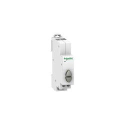
This Acti9 iPB product is a modular pusbutton used to control electric circuits. It has a normally open contact (1 NO) for each push-button. The 2 push-buttons are grey. It comes with staggered terminals to simplify connection. The tightening torque of connection is 1N.m.
Main
| Characteristic | Value(s) |
|---|---|
| range of product | Acti9 |
| product name | Acti9 iPB |
| Product or component type | Push-button |
| Device short name | iPB |
| Standards | IEC 60947-5-1 IEC 60669-1 |
Complementary
| Characteristic | Value(s) |
|---|---|
| Contacts type and composition | 1 NO |
| [Ie] rated operational current | 20 A |
| [Ue] rated operational voltage | 250 V AC |
| Control type | 2 push-button grey |
| Mounting mode | Fixed |
| Mounting support | 35 mm symmetrical DIN rail |
| Comb busbar and distribution block compatibility | Upside: Clario Upside: Librio Upside: ProDis |
| 9 mm pitches | 2 |
| Height | 82 mm |
| Width | 18 mm |
| Depth | 71.5 mm |
| Colour | White |
| Electrical durability | AC-22: 30000 cycles AC 50/60 Hz |
| Connections - terminals | Staggered tunnel terminal1 cable(s) 0.5 mm² rigid Staggered tunnel terminal1 cable(s) 0.5 mm² flexible Staggered tunnel terminal1 cable(s) 0.5 mm² flexible with ferrule Staggered tunnel terminal2 cable(s) 2.5 mm² rigid Staggered tunnel terminal2 cable(s) 2.5 mm² flexible Staggered tunnel terminal2 cable(s) 2.5 mm² flexible with ferrule |
| Wire stripping length | 9 mm |
| Tightening torque | 1 N.m |

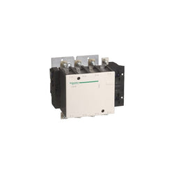
TeSys F contactor, 3 poles (3NO), 265A/1000V AC-3, for motor applications up to 132kW@400V. It provides a low sealed consumption 48V 40-400Hz AC coil, bolt terminals for bars or cables with lugs. For high operating rates until 2400 cycles/hour and environments until 55°C, it procures high reliability and durability. It makes installation and maintenance easy thanks to its drawer-mounted coil and a large choice of add-on blocks and accessories (to be ordered separately). Multi standards certified (IEC, UL, CSA, CCC, EAC, Marine), Green Premium compliant (RoHS/REACh).
Main
| Characteristic | Value(s) |
|---|---|
| Range | TeSys |
| Range of Product | TeSys F |
| Product or Component Type | Contactor |
| Device short name | LC1F |
| Contactor application | Resistive load Motor control |
| Utilisation category | AC-3 AC-4 AC-1 |
| Poles description | 3P |
| [Ue] rated operational voltage | <= 1000 V AC-1 <= 690 V AC-3 <= 690 V AC-4 <= 460 V DC |
| [Uc] control circuit voltage | 48 V AC 40...400 Hz |
| [Ie] rated operational current | 350 A (at <104 °F (40 °C)) at <= 440 V AC AC-1 265 A (at <131 °F (55 °C)) at <= 440 V AC AC-3 |
Complementary
| Characteristic | Value(s) |
|---|---|
| [Uimp] rated impulse withstand voltage | 8 kV |
| [Ith] conventional free air thermal current | 350 A (at 104 °F (40 °C)) |
| Rated breaking capacity | 2120 A conforming to IEC 60947-4-1 |
| [Icw] rated short-time withstand current | 2200 A 104 °F (40 °C) - 10 s 1230 A 104 °F (40 °C) - 30 s 950 A 104 °F (40 °C) - 1 min 620 A 104 °F (40 °C) - 3 min 480 A 104 °F (40 °C) - 10 min |
| Associated fuse rating | 315 A aM at <= 440 V 400 A gG at <= 440 V |
| Average impedance | 0.3 mOhm - Ith 350 A 50 Hz |
| [Ui] rated insulation voltage | 1000 V IEC 60947-4-1 1500 V VDE 0110 group C |
| Power dissipation per pole | 37 W AC-1 21 W AC-3 |
| Overvoltage category | III |
| power pole contact composition | 3 NO |
| Motor power kW | 132 kW at 380...400 V AC 50/60 Hz (AC-3) 140 kW at 415 V AC 50/60 Hz (AC-3) 140 kW at 440 V AC 50/60 Hz (AC-3) 160 kW at 500 V AC 50/60 Hz (AC-3) 160 kW at 660...690 V AC 50/60 Hz (AC-3) 147 kW at 1000 V AC 50/60 Hz (AC-3) 75 kW at 220...230 V AC 50/60 Hz (AC-3) 51 kW at 400 V AC 50/60 Hz (AC-4) |
| Control circuit voltage limits | Operational 0.85...1.1 Uc 40...400 Hz 131 °F (55 °C)) Drop-out 0.15...0.2 Uc 40...400 Hz 131 °F (55 °C)) |
| Mechanical durability | 10 Mcycles |
| Inrush power in VA | 650 VA, 40...400 Hz 0.9 68 °F (20 °C)) |
| Hold-in power consumption in VA | 10 VA, 40...400 Hz 0.9 68 °F (20 °C)) |
| Maximum operating rate | 2400 cyc/h 131 °F (55 °C) |
| Operating time | 40...65 ms closing 100...170 ms opening |
| Connections - terminals | Control circuit screw clamp terminals 1 0.002â¦0.006 in² (1â¦4 mm²)flexible without cable end Control circuit screw clamp terminals 2 0.002â¦0.006 in² (1â¦4 mm²)flexible without cable end Control circuit screw clamp terminals 1 0.002â¦0.006 in² (1â¦4 mm²)flexible with cable end Control circuit screw clamp terminals 2 0.002â¦0.004 in² (1â¦2.5 mm²)flexible with cable end Control circuit screw clamp terminals 1 0.002â¦0.006 in² (1â¦4 mm²)solid without cable end Control circuit screw clamp terminals 2 0.002â¦0.006 in² (1â¦4 mm²)solid without cable end Power circuit bar 2 32 x 4 mm Power circuit lugs-ring terminals 1 0.4 in² (240 mm²) Power circuit connector 1 0.4 in² (240 mm²) Power circuit bolted connection |
| Tightening torque | Control circuit 10.6 lbf.in (1.2 N.m) Power circuit 309.8 lbf.in (35 N.m) |
| Mounting Support | Plate |
| Heat dissipation | 8 W |
| motor power range | 55â¦100 kW 200â¦240 V 3 phase 110â¦220 kW 480â¦500 V 3 phase 110â¦220 kW 380â¦440 V 3 phase |
| Motor starter type | Direct on-line contactor |
| Contactor coil voltage | 48 V AC standard |
| Standards | IEC 60947-4-1 EN 60947-1 EN 60947-4-1 JIS C8201-4-1 IEC 60947-1 |
| Product Certifications | RINA RMRoS CB CSA BV ABS LROS (Lloyds register of shipping) DNV UL UKCA |
| Compatibility code | LC1F |
| Control circuit type | AC 40...400 Hz |
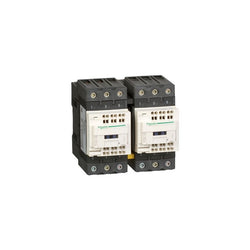
TeSys Deca reversing contactor, 3 poles (3NO), for motor control applications up to 65A/690V AC-3 (30kW@400V). It provides 220V DC coils with transient suppressor module, 2NO+2NC built-in auxiliary contacts (NC mirror contacts), power connection by EverLink BTR screw connectors, control by screw clamp terminals. For operating rates until 3600 cycles/hour and environments until 60°C, it procures high reliability and durability. Compact (119mm width), DIN-rail mounting or screw fixing. With pre-wired reversing power connections, mechanical interlock (without electrical interlocking). Multi standards certified (IEC, UL, CSA, CCC, EAC, Marine), Green Premium compliant (RoHS/REACh).
Main
| Characteristic | Value(s) |
|---|---|
| Range | TeSys |
| product name | TeSys Deca |
| Product or Component Type | Reversing contactor |
| Device short name | LC2D |
| Contactor application | Resistive load Motor control |
| Utilisation category | AC-1 AC-3 |
| Device presentation | Preassembled with reversing power busbar |
| Poles description | 3P |
| power pole contact composition | 3 NO |
| [Ue] rated operational voltage | Power circuit <= 690 V AC 25...400 Hz Power circuit <= 300 V DC |
| [Ie] rated operational current | 80 A (at <140 °F (60 °C)) at <= 440 V AC AC-1 for power circuit 65 A (at <140 °F (60 °C)) at <= 440 V AC AC-3 for power circuit |
| Motor power kW | 18.5 kW at 220...230 V AC 50 Hz 30 kW at 380...400 V AC 50 Hz 37 kW at 415...440 V AC 50 Hz 37 kW at 500 V AC 50 Hz 37 kW at 660...690 V AC 50 Hz |
| motor power HP (UL / CSA) | 40 hp at 460/480 V AC 60 Hz for 3 phase motors 5 hp at 115 V AC 60 Hz for 1 phase motors 10 hp at 230/240 V AC 60 Hz for 1 phase motors 20 hp at 200/208 V AC 60 Hz for 3 phase motors 20 hp at 230/240 V AC 60 Hz for 3 phase motors 50 hp at 575/600 V AC 60 Hz for 3 phase motors |
| Control circuit type | DC standard |
| [Uc] control circuit voltage | 220 V DC |
| Auxiliary contact composition | 1 NO + 1 NC |
| [Uimp] rated impulse withstand voltage | 6 kV IEC 60947 |
| Overvoltage category | III |
| [Ith] conventional free air thermal current | 10 A (at 140 °F (60 °C)) for signalling circuit 80 A (at 140 °F (60 °C)) for power circuit |
| Irms rated making capacity | 140 A AC for signalling circuit conforming to IEC 60947-5-1 250 A DC for signalling circuit conforming to IEC 60947-5-1 1000 A at 440 V for power circuit conforming to IEC 60947 |
| Rated breaking capacity | 1000 A at 440 V for power circuit conforming to IEC 60947 |
| [Icw] rated short-time withstand current | 520 A 104 °F (40 °C) - 10 s for power circuit 900 A 104 °F (40 °C) - 1 s for power circuit 110 A 104 °F (40 °C) - 10 min for power circuit 260 A 104 °F (40 °C) - 1 min for power circuit 100 A - 1 s for signalling circuit 120 A - 500 ms for signalling circuit 140 A - 100 ms for signalling circuit |
| Associated fuse rating | 10 A gG for signalling circuit conforming to IEC 60947-5-1 125 A gG at <= 690 V coordination type 1 for power circuit 125 A gG at <= 690 V coordination type 2 for power circuit |
| Average impedance | 1.5 mOhm - Ith 80 A 50 Hz for power circuit |
| [Ui] rated insulation voltage | Power circuit 690 V IEC 60947-4-1 Power circuit 600 V CSA Power circuit 600 V UL Signalling circuit 690 V IEC 60947-1 Signalling circuit 600 V CSA Signalling circuit 600 V UL |
| Electrical durability | 1.45 Mcycles 65 A AC-3 <= 440 V 1.4 Mcycles 80 A AC-1 <= 440 V |
| Power dissipation per pole | 9.6 W AC-1 6.3 W AC-3 |
| Front cover | With |
| Interlocking type | Mechanical |
| Mounting Support | Rail Plate |
| Standards | CSA C22.2 No 14 EN 60947-4-1 EN 60947-5-1 IEC 60947-4-1 IEC 60947-5-1 UL 508 |
| Product Certifications | CCC GOST UL CSA |
| Connections - terminals | Control circuit screw clamp terminals 1 0.002â¦0.006 in² (1â¦4 mm²)flexible without cable end Control circuit screw clamp terminals 2 0.002â¦0.006 in² (1â¦4 mm²)flexible without cable end Control circuit screw clamp terminals 1 0.002â¦0.006 in² (1â¦4 mm²)flexible with cable end Control circuit screw clamp terminals 2 0.002â¦0.004 in² (1â¦2.5 mm²)flexible with cable end Control circuit screw clamp terminals 1 0.002â¦0.006 in² (1â¦4 mm²)solid Control circuit screw clamp terminals 2 0.002â¦0.006 in² (1â¦4 mm²)solid Power circuit EverLink BTR screw connectors 1 0.002â¦0.05 in² (1â¦35 mm²)flexible without cable end Power circuit EverLink BTR screw connectors 2 0.002â¦0.04 in² (1â¦25 mm²)flexible without cable end Power circuit EverLink BTR screw connectors 1 0.002â¦0.05 in² (1â¦35 mm²)flexible with cable end Power circuit EverLink BTR screw connectors 2 0.002â¦0.04 in² (1â¦25 mm²)flexible with cable end Power circuit EverLink BTR screw connectors 1 0.002â¦0.05 in² (1â¦35 mm²)solid Power circuit EverLink BTR screw connectors 2 0.002â¦0.04 in² (1â¦25 mm²)solid |
| Tightening torque | Control circuit 15.05 lbf.in (1.7 N.m) screw clamp terminals flat à 6 mm Control circuit 15.05 lbf.in (1.7 N.m) screw clamp terminals Philips No 2 Power circuit 70.8 lbf.in (8 N.m) EverLink BTR screw connectors 0.04â¦0.05 in² (25â¦35 mm²) hexagonal 0.2 in (4 mm) Power circuit 44.3 lbf.in (5 N.m) EverLink BTR screw connectors 0.002â¦0.04 in² (1â¦25 mm²) hexagonal 0.2 in (4 mm) |
| Operating time | 16...24 ms opening 42.5...57.5 ms closing |
| Safety reliability level | B10d = 1369863 cycles contactor with nominal load EN/ISO 13849-1 B10d = 20000000 cycles contactor with mechanical load EN/ISO 13849-1 |
| Mechanical durability | 10 Mcycles |
| Maximum operating rate | 3600 cyc/h 140 °F (60 °C) |
Complementary
| Characteristic | Value(s) |
|---|---|
| Coil technology | Built-in bidirectional peak limiting diode suppressor |
| Control circuit voltage limits | 0.1...0.3 Uc (-40â¦158 °F (-40â¦70 °C)):drop-out DC 0.75...1.25 Uc (-40â¦140 °F (-40â¦60 °C)):operational DC 1...1.25 Uc (140â¦158 °F (60â¦70 °C)):operational DC |
| Time constant | 34 ms |
| Inrush power in W | 19 W 68 °F (20 °C)) |
| Hold-in power consumption in W | 7.4 W 68 °F (20 °C) |
| Auxiliary contacts type | Mechanically linked 1 NO + 1 NC IEC 60947-5-1 Mirror contact 1 NC IEC 60947-4-1 |
| Signalling circuit frequency | 25...400 Hz |
| Minimum switching current | 5 mA for signalling circuit |
| Minimum switching voltage | 17 V for signalling circuit |
| Non-overlap time | 1.5 ms on de-energisation between NC and NO contact 1.5 ms on energisation between NC and NO contact |
| Insulation resistance | > 10 MOhm for signalling circuit |
Main
| Characteristic | Value(s) |
|---|---|
| Range | TeSys |
| product name | TeSys Deca |
| Product or Component Type | Reversing contactor |
| Device short name | LC2D |
| Contactor application | Motor control Resistive load |
| Utilisation category | AC-1 AC-3 |
| Device presentation | Preassembled with reversing power busbar |
| Poles description | 3P |
| power pole contact composition | 3 NO |
| [Ue] rated operational voltage | Power circuit <= 690 V AC 25...400 Hz Power circuit <= 300 V DC |
| [Ie] rated operational current | 50 A (at <140 °F (60 °C)) at <= 440 V AC AC-3 for power circuit 80 A (at <140 °F (60 °C)) at <= 440 V AC AC-1 for power circuit |
| Motor power kW | 15 kW at 220...230 V AC 50 Hz 22 kW at 380...400 V AC 50 Hz 30 kW at 500 V AC 50 Hz 33 kW at 660...690 V AC 50 Hz 25 kW at 415 V AC 50 Hz 30 kW at 440 V AC 50 Hz |
| motor power HP (UL / CSA) | 3 hp at 115 V AC 60 Hz for 1 phase motors 7.5 hp at 230/240 V AC 60 Hz for 1 phase motors 15 hp at 200/208 V AC 60 Hz for 3 phase motors 15 hp at 230/240 V AC 60 Hz for 3 phase motors 40 hp at 460/480 V AC 60 Hz for 3 phase motors 40 hp at 575/600 V AC 60 Hz for 3 phase motors |
| Control circuit type | AC 50/60 Hz |
| [Uc] control circuit voltage | 100 V AC 50/60 Hz |
| Auxiliary contact composition | 1 NO + 1 NC |
| [Uimp] rated impulse withstand voltage | 6 kV IEC 60947 |
| Overvoltage category | III |
| [Ith] conventional free air thermal current | 10 A (at 140 °F (60 °C)) for signalling circuit 80 A (at 140 °F (60 °C)) for power circuit |
| Irms rated making capacity | 140 A AC for signalling circuit conforming to IEC 60947-5-1 250 A DC for signalling circuit conforming to IEC 60947-5-1 900 A at 440 V for power circuit conforming to IEC 60947 |
| Rated breaking capacity | 900 A at 440 V for power circuit conforming to IEC 60947 |
| [Icw] rated short-time withstand current | 400 A 104 °F (40 °C) - 10 s for power circuit 810 A 104 °F (40 °C) - 1 s for power circuit 84 A 104 °F (40 °C) - 10 min for power circuit 208 A 104 °F (40 °C) - 1 min for power circuit 100 A - 1 s for signalling circuit 120 A - 500 ms for signalling circuit 140 A - 100 ms for signalling circuit |
| Associated fuse rating | 10 A gG for signalling circuit conforming to IEC 60947-5-1 100 A gG at <= 690 V coordination type 1 for power circuit 100 A gG at <= 690 V coordination type 2 for power circuit |
| Average impedance | 1.5 mOhm - Ith 80 A 50 Hz for power circuit |
| [Ui] rated insulation voltage | Power circuit 690 V IEC 60947-4-1 Power circuit 600 V CSA Power circuit 600 V UL Signalling circuit 690 V IEC 60947-1 Signalling circuit 600 V CSA Signalling circuit 600 V UL |
| Electrical durability | 1.45 Mcycles 50 A AC-3 <= 440 V 1.1 Mcycles 80 A AC-1 <= 440 V |
| Power dissipation per pole | 3.7 W AC-3 9.6 W AC-1 |
| Front cover | With |
| Interlocking type | Mechanical |
| Mounting Support | Rail Plate |
| Standards | CSA C22.2 No 14 EN 60947-4-1 EN 60947-5-1 IEC 60947-4-1 IEC 60947-5-1 UL 508 |
| Product Certifications | CSA UL CCC GOST |
| Connections - terminals | Control circuit spring terminals 1 0.004 in² (2.5 mm²)flexible without cable end Control circuit spring terminals 2 0.004 in² (2.5 mm²)flexible without cable end Power circuit EverLink BTR screw connectors 1 0.002â¦0.05 in² (1â¦35 mm²)flexible without cable end Power circuit EverLink BTR screw connectors 2 0.002â¦0.04 in² (1â¦25 mm²)flexible without cable end Power circuit EverLink BTR screw connectors 1 0.002â¦0.05 in² (1â¦35 mm²)flexible with cable end Power circuit EverLink BTR screw connectors 2 0.002â¦0.04 in² (1â¦25 mm²)flexible with cable end Power circuit EverLink BTR screw connectors 1 0.002â¦0.05 in² (1â¦35 mm²)solid Power circuit EverLink BTR screw connectors 2 0.002â¦0.04 in² (1â¦25 mm²)solid |
| Tightening torque | Power circuit 70.8 lbf.in (8 N.m) EverLink BTR screw connectors 0.04â¦0.05 in² (25â¦35 mm²) hexagonal 0.2 in (4 mm) Power circuit 44.3 lbf.in (5 N.m) EverLink BTR screw connectors 0.004â¦0.04 in² (2.5â¦25 mm²) hexagonal 0.2 in (4 mm) |
| Operating time | 4...19 ms opening 12...26 ms closing |
| Safety reliability level | B10d = 1369863 cycles contactor with nominal load EN/ISO 13849-1 B10d = 20000000 cycles contactor with mechanical load EN/ISO 13849-1 |
| Mechanical durability | 6 Mcycles |
| Maximum operating rate | 3600 cyc/h 140 °F (60 °C) |
Complementary
| Characteristic | Value(s) |
|---|---|
| Coil technology | Without built-in suppressor module |
| Control circuit voltage limits | 0.3...0.6 Uc (-40â¦158 °F (-40â¦70 °C)):drop-out AC 50/60 Hz 0.8...1.1 Uc (-40â¦140 °F (-40â¦60 °C)):operational AC 50 Hz 0.85...1.1 Uc (-40â¦140 °F (-40â¦60 °C)):operational AC 60 Hz 1...1.1 Uc (140â¦158 °F (60â¦70 °C)):operational AC 50/60 Hz |
| Inrush power in VA | 140 VA 60 Hz cos phi 0.75 (at 68 °F (20 °C)) 160 VA 50 Hz cos phi 0.75 (at 68 °F (20 °C)) |
| Hold-in power consumption in VA | 13 VA 60 Hz cos phi 0.3 (at 68 °F (20 °C)) 15 VA 50 Hz cos phi 0.3 (at 68 °F (20 °C)) |
| Heat dissipation | 4â¦5 W 50/60 Hz |
| Auxiliary contacts type | Mechanically linked 1 NO + 1 NC IEC 60947-5-1 Mirror contact 1 NC IEC 60947-4-1 |
| Signalling circuit frequency | 25...400 Hz |
| Minimum switching current | 5 mA for signalling circuit |
| Minimum switching voltage | 17 V for signalling circuit |
| Non-overlap time | 1.5 ms on de-energisation between NC and NO contact 1.5 ms on energisation between NC and NO contact |
| Insulation resistance | > 10 MOhm for signalling circuit |