
 1 year warranty


Main
| Characteristic | Value(s) |
|---|---|
| Range of Product | Lexium integrated drive |
| Product or Component Type | Motion integrated drive |
| Device short name | ILS |
| Motor Type | 3-phase stepper motor |
| Number of motor poles | 6 |
| Phase | Single phase |
| [Us] rated supply voltage | 24 V 36 V |
| Network type | DC |
| Communication interface | Pulse/direction 5 V RS422, Integrated |
| Length | 9.7 in (247.3 mm) |
| Winding type | High speed of rotation and medium torque |
| Electrical Connection | Printed circuit board connector |
| Holding brake | With |
| Gear box type | Without |
| Nominal speed | 100 rpm 24 V 300 rpm 36 V |
| Nominal torque | 39.8 lbf.in (4.5 N.m) |
| Holding torque | 53.1 lbf.in (6 N.m) holding brake 39.8 lbf.in (4.5 N.m) |
Complementary
| Characteristic | Value(s) |
|---|---|
| Mounting Support | Flange |
| Motor flange size | 3.3 in (85 mm) |
| Number of motor stacks | 3 |
| Centring collar diameter | 2.4 in (60 mm) |
| centring collar depth | 0.08 in (2 mm) |
| Number of mounting holes | 4 |
| Mounting holes diameter | 0.3 in (6.5 mm) |
| Circle diameter of the mounting holes | 3.9 in (99 mm) |
| Feedback type | Index pulse |
| Shaft end | Untapped |
| Second shaft | Without second shaft end |
| Shaft diameter | 0.6 in (14 mm) |
| Shaft length | 1.2 in (30 mm) |
| Supply voltage limits | 18â¦40 V |
| Current consumption | 6000 mA maximum continuous |
| Associated fuse rating | 10 A |
| Input/output type | 4 signals (each be used as input or output) |
| Voltage state 0 guaranteed | -3...4.5 V |
| Voltage state 1 guaranteed | 15...30 V |
| Discrete input current | 10 mA at 24 V safety input |
| Discrete output voltage | 23...25 V |
| Maximum switching current | 100 mA per output 200 mA total |
| Protection Type | Overload of output voltage Safe torque off Short circuit of the output voltage |
| Peak stall torque | 39.8 lbf.in (4.5 N.m) |
| Continuous stall torque | 39.8 lbf.in (4.5 N.m) |
| Speed feedback resolution | 1.8°, 0.9°, 0.72°, 0.36°, 0.18°, 0.09°, 0.072°, 0.036° 200, 400, 500, 1000, 2000, 4000, 5000, 10000 steps |
| Accuracy error | +/- 6 arc min |
| Rotor inertia | 3.5 kg.cm² |
| Maximum mechanical speed | 2000 rpm |
| Maximum radial force Fr | 110 N |
| Maximum axial force Fa | 170 N tensile force) 30 N force pressure) |
| Service life in hours | 20000 h bearing |
| Brake pull-in power | 22 W |
| Brake release time | 40 ms |
| Brake application time | 20 ms |
| Marking | CE |
| type of cooling | Natural convection |
| Product Weight | 14.3 lb(US) (6.5 kg) |

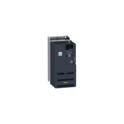
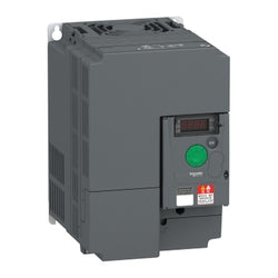
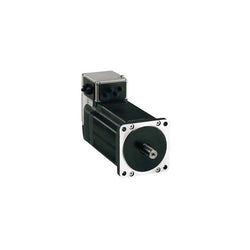
integrated drive ILS with stepper motor - 24..36V- I/O for motion sequence- 3.5A
Main
| Characteristic | Value(s) |
|---|---|
| Range of Product | Altivar Machine ATV340 |
| Product or Component Type | Variable speed drive |
| Product Specific Application | Machine |
| Mounting Mode | Cabinet mount |
| Variant | Standard version |
| Communication Port Protocol | Sercos Modbus serial |
| Phase | 3 phase |
| Supply frequency | 50...60 Hz +/- 5 % |
| [Us] rated supply voltage | 380...480 V - 15...10 % |
| nominal output current | 32.0 A |
| Motor power kW | 18.5 kW normal duty 15 kW heavy duty |
| Maximum Horse Power Rating | 25 hp normal duty 20 hp heavy duty |
| EMC filter | Class C3 EMC filter integrated |
| IP degree of protection | IP20 |
Complementary
| Characteristic | Value(s) |
|---|---|
| Discrete input number | 5 |
| Discrete input type | PTI safe torque off 0â¦30 kHz, 24 V DC 30 V) DI1...DI5 discrete input, 24 V DC 30 V)3.5 kOhm |
| number of preset speeds | 16 preset speeds |
| Discrete output number | 2.0 |
| Discrete output type | Programmable output DQ1, DQ2 30 V DC 100 mA |
| Analogue input number | 2 |
| Analogue input type | AI1 software-configurable current 0...20 mA 250 Ohm 12 bits AI1 software-configurable temperature probe or water level sensor AI1 software-configurable voltage 0...10 V DC 31.5 kOhm 12 bits AI2 software-configurable voltage - 10...10 V DC 31.5 kOhm 12 bits |
| Analogue output number | 1 |
| Analogue output type | Software-configurable voltage AQ1 0...10 V DC 470 Ohm 10 bits Software-configurable current AQ1 0...20 mA 500 Ohm 10 bits |
| Relay output number | 2 |
| Output voltage | <= power supply voltage |
| Relay output type | Relay outputs R1A Relay outputs R1C 100000 cycles Relay outputs R2A Relay outputs R2C 100000 cycles |
| Maximum switching current | Relay output R1C resistive, cos phi = 1 3 A 250 V AC Relay output R1C resistive, cos phi = 1 3 A 30 V DC Relay output R1C inductive, cos phi = 0.4 7 ms 2 A 250 V AC Relay output R1C inductive, cos phi = 0.4 7 ms 2 A 30 V DC Relay output R2C resistive, cos phi = 1 5 A 250 V AC Relay output R2C resistive, cos phi = 1 5 A 30 V DC Relay output R2C inductive, cos phi = 0.4 7 ms 2 A 250 V AC Relay output R2C inductive, cos phi = 0.4 7 ms 2 A 30 V DC |
| Minimum switching current | Relay output R1B 5 mA 24 V DC Relay output R2C 5 mA 24 V DC |
| Physical interface | 2-wire RS 485 |
| Connector Type | 3 RJ45 |
| Method of access | Slave Modbus RTU |
| Transmission Rate | 4.8 kbit/s 9.6 kbit/s 19.2 kbit/s 38.4 kbit/s |
| Transmission frame | RTU |
| Number of addresses | 1â¦247 |
| Data format | 8 bits, configurable odd, even or no parity |
| Type of polarization | No impedance |
| 4 quadrant operation possible | True |
| Asynchronous motor control profile | Variable torque standard Optimized torque mode Constant torque standard |
| Synchronous motor control profile | Reluctance motor Permanent magnet motor |
| Pollution degree | 2 IEC 61800-5-1 |
| Maximum output frequency | 0.599 kHz |
| Acceleration and deceleration ramps | Linear adjustable separately from 0.01...9999 s S, U or customized |
| Motor slip compensation | Automatic whatever the load Adjustable Not available in permanent magnet motor law Can be suppressed |
| Switching frequency | 2...16 kHz adjustable 7...16 kHz with derating factor |
| Nominal switching frequency | 4 kHz |
| Braking to standstill | By DC injection |
| Brake chopper integrated | True |
| Line current | 37.4 A 380 V normal duty) 30.2 A 480 V normal duty) 44.9 A 380 V heavy duty) 35.7 A 480 V heavy duty) |
| Line current | 44.9 A 380 V without line choke heavy duty) 35.7 A 480 V without line choke heavy duty) 37.4 A 380 V with external line choke normal duty) 30.2 A 480 V with external line choke normal duty) 28.7 A 380 V with external line choke heavy duty) 23 A 480 V with external line choke heavy duty) |
| Maximum Input Current per Phase | 44.9 A |
| Maximum output voltage | 480 V |
| Apparent power | 28.3 kVA 480 V normal duty) 29.7 kVA 480 V heavy duty) |
| Maximum transient current | 42.9 A 60 s normal duty) 48 A 60 s heavy duty) 52.7 A 2 s normal duty) 58 A 2 s heavy duty) |
| Electrical connection | Screw terminal 0.2...2.5 mm² control Screw terminal 6...25 mm² line side Screw terminal 6...25 mm² DC bus Screw terminal 4...25 mm² motor |
| Prospective line Isc | 22 kA |
| Base load current at high overload | 32.0 A |
| Base load current at low overload | 39.0 A |
| Power dissipation in W | Natural convection 18 W 380 V 4 kHz heavy duty) Forced convection 346 W 380 V 4 kHz heavy duty) Natural convection 21 W 380 V 4 kHz normal duty) Forced convection 411 W 380 V 4 kHz normal duty) |
| Electrical connection | Control screw terminal 0.2...2.5 mm² AWG 24...AWG 12 Line side screw terminal 6...25 mm² AWG 8...AWG 3 DC bus screw terminal 6...25 mm² AWG 8...AWG 3 Motor screw terminal 4...25 mm² AWG 10...AWG 3 |
| With safety function Safely Limited Speed (SLS) | True |
| With safety function Safe brake management (SBC/SBT) | True |
| With safety function Safe Operating Stop (SOS) | False |
| With safety function Safe Position (SP) | False |
| With safety function Safe programmable logic | False |
| With safety function Safe Speed Monitor (SSM) | False |
| With safety function Safe Stop 1 (SS1) | True |
| With sft fct Safe Stop 2 (SS2) | False |
| With safety function Safe torque off (STO) | True |
| With safety function Safely Limited Position (SLP) | False |
| With safety function Safe Direction (SDI) | False |
| Protection type | Thermal protection motor Safe torque off motor Motor phase loss motor Thermal protection drive Safe torque off drive Overheating drive Overcurrent drive Output overcurrent between motor phase and earth drive Output overcurrent between motor phases drive Short-circuit between motor phase and earth drive Short-circuit between motor phases drive Motor phase loss drive DC Bus overvoltage drive Line supply overvoltage drive Line supply undervoltage drive Input supply loss drive Exceeding limit speed drive Break on the control circuit drive |
| Width | 7.09 in (180.0 mm) |
| Height | 15.2 in (385.0 mm) |
| Depth | 9.8 in (249.0 mm) |
| Product Weight | 20.9 lb(US) (9.5 kg) |
| Continuous output current | 39 A 4 kHz normal duty 32 A 4 kHz heavy duty |

Main
| Characteristic | Value(s) |
|---|---|
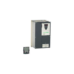
| Range of Product | Altivar 71 |
| Product or Component Type | Variable speed drive |
| Product Specific Application | Complex, high-power machines |
| Component name | ATV71 |
| Motor power kW | 22 kW, 3 phase 690 V 18.5 kW, 3 phase 500 V |
| Maximum Horse Power Rating | 25 hp, 3 phase 575 V |
| Maximum motor cable length | 32.8 ft (10 m) shielded cable 32.8 ft (10 m) unshielded cable |
| power supply voltage | 500...690 V - 15...10 % |
| Phase | 3 phase |
| Line current | 24 A 600 V 3 phase / 25 hp 27 A 690 V 3 phase 22 kW 29 A 500 V 3 phase 18.5 kW |
| EMC filter | Integrated |
| Assembly style | With heat sink |
| Variant | Reinforced version |
| Prospective line Isc | 22 kA 3 phase |
| Nominal output current | 27 A 4 kHz 575 V 3 phase / 25 hp 27 A 4 kHz 690 V 3 phase 22 kW 29 A 4 kHz 500 V 3 phase 18.5 kW |
| Maximum transient current | 43.5 A 60 s 3 phase 18.5 kW 47.85 A 2 s 3 phase / 25 hp 47.85 A 2 s 3 phase 22 kW |
| Output frequency | 0.1â¦500 Hz |
| Nominal switching frequency | 4 kHz |
| Switching frequency | 2.5...6 kHz adjustable 4...6 kHz with derating factor |
| Asynchronous motor control profile | Voltage/frequency ratio (2 or 5 points) ENA (Energy adaptation) system for unbalanced loads Sensorless flux vector control (SFVC) (voltage or current vector) Flux vector control (FVC) with sensor (current vector) |
| Type of polarization | No impedance Modbus |
Complementary
| Characteristic | Value(s) |
|---|---|
| Product destination | Asynchronous motors Synchronous motors |
| power supply voltage limits | 425â¦759 V |
| power supply frequency | 50...60 Hz - 5...5 % |
| power supply frequency limits | 47.5...63 Hz |
| Speed range | 1â¦100 asynchronous motor in open-loop mode, without speed feedback 1â¦1000 asynchronous motor in closed-loop mode with encoder feedback 1â¦50 synchronous motor in open-loop mode, without speed feedback |
| Speed accuracy | +/- 0.01 % of nominal speed in closed-loop mode with encoder feedback 0.2 Tn to Tn +/- 10 % of nominal slip without speed feedback 0.2 Tn to Tn |
| Torque accuracy | +/- 15 % in open-loop mode, without speed feedback +/- 5 % in closed-loop mode with encoder feedback |
| Transient overtorque | 170 % +/- 10 % 60 s every 10 minutes 220 % +/- 10 % 2 s |
| Braking torque | <= 150 % with braking or hoist resistor 30 % without braking resistor |
| Synchronous motor control profile | Vector control without speed feedback |
| Regulation loop | Adjustable PI regulator |
| Motor slip compensation | Automatic whatever the load Not available in voltage/frequency ratio (2 or 5 points) Adjustable Suppressable |
| diagnostic | 1 LED (red) for drive voltage |
| Output voltage | <= power supply voltage |
| Insulation | Electrical between power and control |
| type of cable for mounting in an enclosure | With a NEMA Type1 kit 3 UL 508 cable 104 °F (40 °C), copper 75 °C / PVC With an IP21 or an IP31 kit 3 IEC cable 104 °F (40 °C), copper 70 °C / PVC Without mounting kit 1 IEC cable 113 °F (45 °C), copper 70 °C / PVC Without mounting kit 1 IEC cable 113 °F (45 °C), copper 90 °C / XLPE/EPR |
| Electrical connection | Terminal 2.5 mm², AWG 14 AI1-/AI1+, AI2, AO1, R1A, R1B, R1C, R2A, R2B, LI1...LI6, PWR) Terminal 50 mm², AWG 1/0 L1/R, L2/S, L3/T, U/T1, V/T2, W/T3, PC/-, PO, PA/+, PA, PB) |
| Tightening torque | 5.3 lbf.in (0.6 N.m) AI1-/AI1+, AI2, AO1, R1A, R1B, R1C, R2A, R2B, LI1...LI6, PWR) 106.2 lbf.in (12 N.m), 102.2 lb.in L1/R, L2/S, L3/T, U/T1, V/T2, W/T3, PC/-, PO, PA/+, PA, PB) |
| Supply | Internal supply for reference potentiometer (1 to 10 kOhm) 10.5 V DC +/- 5 %, <10 mA overload and short-circuit protection Internal supply 24 V DC 21â¦27 V), <200 mA overload and short-circuit protection |
| Analogue input number | 2 |
| Analogue input type | AI1-/Al1+ bipolar differential voltage +/- 10 V DC 24 V max 11 bits + sign AI2 software-configurable current 0...20 mA 242 Ohm 11 bits AI2 software-configurable voltage 0...10 V DC 24 V max 30000 Ohm 11 bits |
| input sampling time | 2 ms +/- 0.5 ms AI1-/Al1+) - analog 2 ms +/- 0.5 ms Al2) - analog 2 ms +/- 0.5 ms LI1...LI5) - discrete 2 ms +/- 0.5 ms LI6)if configured as logic input - discrete |
| Response time | <= 100 ms in STO (Safe Torque Off) AO1 2 ms +/- 0.5 ms analog R1A, R1B, R1C 7 ms +/- 0.5 ms discrete R2A, R2B 7 ms +/- 0.5 ms discrete |
| absolute accuracy precision | +/- 0.6 % AI1-/Al1+) for a temperature variation 60 °C +/- 0.6 % AI2) for a temperature variation 60 °C +/- 1 % AO1) for a temperature variation 60 °C |
| Linearity error | +/- 0.15 % of maximum value AI1-/Al1+, AI2) +/- 0.2 % AO1) |
| Analogue output number | 1 |
| Analogue output type | AO1 software-configurable logic output 10 V 20 mA AO1 software-configurable current 0...20 mA 500 Ohm 10 bits AO1 software-configurable voltage 0...10 V DC 470 Ohm 10 bits |
| Discrete output number | 2 |
| Discrete output type | Configurable relay logic R1A, R1B, R1C) NO/NC - 100000 cycles Configurable relay logic R2A, R2B) NO - 100000 cycles |
| Minimum switching current | 3 mA 24 V DC configurable relay logic |
| Maximum switching current | R1, R2 2 A 250 V AC inductive, cos phi = 0.4 R1, R2 2 A 30 V DC inductive, cos phi = 0.4 R1, R2 5 A 250 V AC resistive, cos phi = 1 R1, R2 5 A 30 V DC resistive, cos phi = 1 |
| Discrete input number | 7 |
| Discrete input type | LI1...LI5 programmable 24 V DC level 1 PLC 3500 Ohm LI6 switch-configurable 24 V DC level 1 PLC 3500 Ohm LI6 switch-configurable PTC probe 0â¦6 1500 Ohm PWR safety input 24 V DC 1500 Ohm ISO 13849-1 level d |
| Discrete input logic | Negative logic (sink) LI1...LI5), > 16 V, < 10 V Positive logic (source) LI1...LI5), < 5 V, > 11 V Negative logic (sink) LI6)if configured as logic input, > 16 V, < 10 V Positive logic (source) LI6)if configured as logic input, < 5 V, > 11 V |
| Acceleration and deceleration ramps | Automatic adaptation of ramp if braking capacity exceeded, by using resistor Linear adjustable separately from 0.01 to 9000 s S, U or customized |
| Braking to standstill | By DC injection |
| Protection type | Against exceeding limit speed drive Against input phase loss drive Break on the control circuit drive Input phase breaks drive Line supply overvoltage drive Line supply undervoltage drive Overcurrent between output phases and earth drive Overheating protection drive Overvoltages on the DC bus drive Short-circuit between motor phases drive Thermal protection drive Motor phase break motor Power removal motor Thermal protection motor |
| Insulation resistance | > 1 mOhm 500 V DC for 1 minute to earth |
| Frequency resolution | Analog input 0.024/50 Hz Display unit 0.1 Hz |
| Communication Port Protocol | CANopen Modbus |
| Connector type | 1 RJ45 on front face)Modbus 1 RJ45 on terminal)Modbus Male SUB-D 9 on RJ45CANopen |
| Physical interface | 2-wire RS 485 Modbus |
| Transmission frame | RTU Modbus |
| Transmission rate | 4800 bps, 9600 bps, 19200 bps, 38.4 Kbps Modbus on terminal 9600 bps, 19200 bps Modbus on front face 20 kbps, 50 kbps, 125 kbps, 250 kbps, 500 kbps, 1 Mbps CANopen |
| Data format | 8 bits, 1 stop, even parity Modbus on front face 8 bits, odd even or no configurable parity Modbus on terminal |
| Number of addresses | 1â¦127 CANopen 1â¦247 Modbus |
| Method of access | Slave CANopen |
| Marking | CE |
| Operating position | Vertical +/- 10 degree |
| Height | 16.5 in (420 mm) |
| Depth | 9.3 in (236 mm) |
| Width | 9.4 in (240 mm) |
| Product Weight | 66.1 lb(US) (30 kg) |
| Option card | Communication card CC-Link Controller inside programmable card Communication card DeviceNet Communication card EtherNet/IP Communication card Fipio I/O extension card Communication card Interbus-S Interface card for encoder Communication card Modbus Plus Communication card Modbus TCP Communication card Modbus/Uni-Telway Overhead crane card Communication card Profibus DP Communication card Profibus DP V1 |
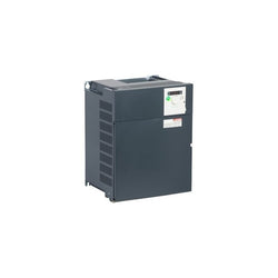
Variable Speed Drive - ATV950 - 7,5kW - 400/480V - with braking unit - IP55

Main
| Characteristic | Value(s) |
|---|---|
| Range of Product | Altivar 61 |
| Product or Component Type | Variable speed drive |
| Product Specific Application | Pumping and ventilation machine |
| Component name | ATV61 |
| Motor power kW | 200 kW, 3 phase 380...480 V 220 kW, 3 phase 380...480 V |
| Maximum Horse Power Rating | 300 hp, 3 phase 380...480 V 350 hp, 3 phase 380...480 V |
| power supply voltage | 380...480 V - 15...10 % |
| supply number of phases | 3 phase |
| Line current | 331 A 480 V 3 phase 200 kW / 300 hp 357 A 380 V 3 phase 200 kW / 300 hp 383 A 480 V 3 phase 220 kW / 350 hp 396 A 380 V 3 phase 220 kW / 350 hp |
| EMC filter | Level 3 EMC filter |
| Variant | Without DC choke |
| Assembly style | With heat sink |
| Apparent power | 235 kVA 380 V 3 phase 200 kW / 300 hp 260.6 kVA 380 V 3 phase 220 kW / 350 hp |
| maximum prospective line Isc | 50 kA 3 phase |
| Maximum transient current | 512.4 A 60 s, 3 phase |
| Nominal switching frequency | 2.5 kHz |
| Switching frequency | 2...8 kHz adjustable 2.5...8 kHz with derating factor |
| asynchronous motor control | Voltage/frequency ratio - Energy Saving, quadratic U/f Voltage/frequency ratio, 5 points Flux vector control without sensor, standard Voltage/frequency ratio, 2 points |
| Synchronous motor control profile | Vector control without sensor, standard |
| Communication Port Protocol | CANopen Modbus |
| Type of polarization | No impedance Modbus |
| Option card | Communication card APOGEE FLN Communication card BACnet Communication card CC-Link Controller inside programmable card Communication card DeviceNet Communication card EtherNet/IP Communication card Fipio I/O extension card Communication card Interbus-S Communication card LonWorks Communication card METASYS N2 Communication card Modbus Plus Communication card Modbus TCP Communication card Modbus/Uni-Telway Multi-pump card Communication card Profibus DP Communication card Profibus DP V1 |
Complementary
| Characteristic | Value(s) |
|---|---|
| Product destination | Asynchronous motors Synchronous motors |
| power supply voltage limits | 323â¦528 V |
| power supply frequency | 50...60 Hz - 5...5 % |
| power supply frequency limits | 47.5...63 Hz |
| Continuous output current | 427 A 2.5 kHz, 380 V - 3 phase 427 A 2.5 kHz, 460 V - 3 phase |
| Output frequency | 0.1â¦500 Hz |
| Speed range | 1â¦100 in open-loop mode, without speed feedback |
| Speed accuracy | +/- 10 % of nominal slip 0.2 Tn to Tn without speed feedback |
| Torque accuracy | +/- 15 % in open-loop mode, without speed feedback |
| Transient overtorque | 130 % of nominal motor torque +/- 10 % 60 s |
| Braking torque | <= 125 % with braking resistor 30 % without braking resistor |
| Regulation loop | Frequency PI regulator |
| Motor slip compensation | Can be suppressed Not available in voltage/frequency ratio (2 or 5 points) Adjustable Automatic whatever the load |
| diagnostic | 1 LED (red) for drive voltage |
| Output voltage | <= power supply voltage |
| electrical isolation | Between power and control terminals |
| type of cable for mounting in an enclosure | With an IP21 or an IP31 kit 3 IEC cable 104 °F (40 °C), copper 70 °C / PVC With UL Type 1 kit 3 UL 508 cable 104 °F (40 °C), copper 75 °C / PVC Without mounting kit 1 IEC cable 113 °F (45 °C), copper 70 °C / PVC Without mounting kit 1 IEC cable 113 °F (45 °C), copper 90 °C / XLPE/EPR |
| Electrical connection | Terminal 2.5 mm² / AWG 14 AI1-/AI1+, AI2, AO1, R1A, R1B, R1C, R2A, R2B, LI1...LI6, PWR) Terminal 120 mm² / 250 kcmil PA, PB) Terminal 2 x 150 mm² / 2 x 350 kcmil L1/R, L2/S, L3/T, U/T1, V/T2, W/T3) Terminal 2 x 150 mm² / 2 x 350 kcmil PC/-, PO, PA/+) |
| Tightening torque | 5.3 lbf.in (0.6 N.m) AI1-/AI1+, AI2, AO1, R1A, R1B, R1C, R2A, R2B, LI1...LI6, PWR) 362.9 lbf.in (41 N.m), 360 lb.in PC/-, PO, PA/+) 212.4 lbf.in (24 N.m), 212 lb.in PA, PB) 362.9 lbf.in (41 N.m), 360 lb.in L1/R, L2/S, L3/T, U/T1, V/T2, W/T3) |
| Supply | Internal supply for reference potentiometer (1 to 10 kOhm) 10.5 V DC, +/- 5 %, <10 mA overload and short-circuit protection Internal supply 24 V DC 21â¦27 V), <200 mA overload and short-circuit protection External supply 24 V DC 19â¦30 V) |
| Analogue input number | 2 |
| Analogue input type | AI1-/Al1+ bipolar differential voltage +/- 10 V DC 24 V max 11 bits + sign AI2 software-configurable current 0...20 mA 242 Ohm 11 bits AI2 software-configurable voltage 0...10 V DC 24 V max 30000 Ohm 11 bits |
| sampling time | 2 ms +/- 0.5 ms AI1-/Al1+) - analog input 2 ms +/- 0.5 ms Al2) - analog input 2 ms +/- 0.5 ms AO1) - analog output 2 ms +/- 0.5 ms LI1...LI5) - discrete input 2 ms +/- 0.5 ms LI6)if configured as logic input - discrete input |
| absolute accuracy precision | +/- 0.6 % AI1-/Al1+) for a temperature variation 60 °C +/- 0.6 % AI2) for a temperature variation 60 °C +/- 1 % AO1) for a temperature variation 60 °C |
| Linearity error | +/- 0.15 % of maximum value AI1-/Al1+) +/- 0.15 % of maximum value AI2) +/- 0.2 % AO1) |
| Analogue output number | 1 |
| Analogue output type | AO1 software-configurable current 0...20 mA 500 Ohm 10 bits AO1 software-configurable voltage 0...10 V DC 470 Ohm 10 bits AO1 software-configurable logic output 10 V, 20 mA |
| Discrete output number | 2 |
| Discrete output type | Configurable relay logic R1A, R1B, R1C) NO/NC - 100000 cycles Configurable relay logic R2A, R2B) NO - 100000 cycles |
| maximum response time | <= 100 ms in STO (Safe Torque Off) R1A, R1B, R1C <= 7 ms +/- 0.5 ms R2A, R2B <= 7 ms +/- 0.5 ms |
| Minimum switching current | 3 mA 24 V DC configurable relay logic |
| Maximum switching current | R1, R2 2 A 250 V AC inductive, cos phi = 0.4 7 ms R1, R2 2 A 30 V DC inductive, cos phi = 0.4 7 ms R1, R2 5 A 250 V AC resistive, cos phi = 1 0 ms R1, R2 5 A 30 V DC resistive, cos phi = 1 0 ms |
| Discrete input number | 7 |
| Discrete input type | Programmable LI1...LI5) 24 V DC <= 30 V)level 1 PLC - 3500 Ohm Switch-configurable LI6) 24 V DC <= 30 V)level 1 PLC - 3500 Ohm Switch-configurable PTC probe LI6)0â¦6 - 1500 Ohm Safety input PWR) 24 V DC <= 30 V) - 1500 Ohm |
| Discrete input logic | Negative logic (sink) LI1...LI5), > 16 V, < 10 V Positive logic (source) LI1...LI5), < 5 V, > 11 V Negative logic (sink) LI6)if configured as logic input, > 16 V, < 10 V Positive logic (source) LI6)if configured as logic input, < 5 V, > 11 V |
| Acceleration and deceleration ramps | S, U or customized Linear adjustable separately from 0.01 to 9000 s Automatic adaptation of ramp if braking capacity exceeded, by using resistor |
| Braking to standstill | By DC injection |
| Protection type | Against exceeding limit speed drive Against input phase loss drive Break on the control circuit drive Input phase breaks drive Line supply overvoltage drive Line supply undervoltage drive Overcurrent between output phases and earth drive Overheating protection drive Overvoltages on the DC bus drive Power removal drive Short-circuit between motor phases drive Thermal protection drive Motor phase break motor Power removal motor Thermal protection motor |
| Insulation resistance | > 1 mOhm 500 V DC for 1 minute to earth |
| Frequency resolution | Analog input 0.024/50 Hz Display unit 0.1 Hz |
| Connector type | 1 RJ45 on front face)Modbus 1 RJ45 on terminal)Modbus Male SUB-D 9 on RJ45CANopen |
| Physical interface | 2-wire RS 485 Modbus |
| Transmission frame | RTU Modbus |
| Transmission rate | 4800 bps, 9600 bps, 19200 bps, 38.4 Kbps Modbus on terminal 9600 bps, 19200 bps Modbus on front face 20 kbps, 50 kbps, 125 kbps, 250 kbps, 500 kbps, 1 Mbps CANopen |
| Data format | 8 bits, 1 stop, even parity Modbus on front face 8 bits, odd even or no configurable parity Modbus on terminal |
| Number of addresses | 1â¦127 CANopen 1â¦247 Modbus |
| Method of access | Slave CANopen |
| Marking | CE |
| Operating position | Vertical +/- 10 degree |
| Product Weight | 242.5 lb(US) (110 kg) |
| Width | 17.3 in (440 mm) |
| Height | 37.4 in (950 mm) |
| Depth | 14.8 in (377 mm) |
variable speed drive ATV310, 11 kW/15hp normal duty, 7.5 kW/10hp heavy duty, 380...460 V, 3 phases, without EMC filter

Main
| Characteristic | Value(s) |
|---|---|
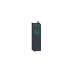
| Range of Product | Altivar Process ATV600 |
| Product Specific Application | Process and utilities |
| Product or Component Type | Variable speed drive |
| Variant | Standard version |
| Device short name | ATV630 |
| Mounting Mode | Wall mount |
| Communication Port Protocol | Modbus TCP Modbus serial Ethernet |
| [Us] rated supply voltage | 600 V - 15...10 % |
| [Us] rated supply voltage | 600 V |
| Relative symmetric mains voltage tolerance | 10 % |
| Relative symmetric network frequency tolerance | 5 % |
| nominal output current | 41.5 A |
| IP degree of protection | IP20 |
| Product destination | Asynchronous motors Synchronous motors |
| EMC filter | Without EMC filter |
| IP degree of protection | IP20IEC 61800-5-1 IP20IEC 60529 |
| Degree of protection | UL type 1 UL 508C |
| type of cooling | Forced convection |
| Supply frequency | 50...60 Hz - 5...5 % |
| Maximum Horse Power Rating | 40 hp 600 V normal duty 30 hp 600 V heavy duty |
| Line current | 40.6 A 600 V normal duty) 32 A 600 V heavy duty) |
| Continuous output current | 41.5 A 2.5 kHz normal duty 34 A 2.5 kHz heavy duty |
| Speed drive output frequency | 0.1â¦500 Hz |
| Safety function | STO (safe torque off) SIL 3 |
| Option card | Slot A communication module, Profibus DP V1 Slot A communication module, PROFINET Slot A communication module, DeviceNet Slot A communication module, Modbus TCP/EtherNet/IP Slot A communication module, CANopen daisy chain RJ45 Slot A communication module, CANopen SUB-D 9 Slot A communication module, CANopen screw terminals Slot A/slot B digital and analog I/O extension module Slot A/slot B output relay extension module Slot A communication module, Ethernet IP/Modbus TCP/MD-Link communication module, BACnet MS/TP communication module, Ethernet Powerlink |
Complementary
| Characteristic | Value(s) |
|---|---|
| Discrete input number | 8 |
| Discrete input type | DI7, DI8 programmable as pulse input 0â¦30 kHz, 24 V DC <= 30 V) |
| Discrete input logic | 16 preset speeds |
| Discrete output number | 0 |
| Discrete output type | Relay outputs R1A, R1B, R1C 250 V AC 3000 mA Relay outputs R1A, R1B, R1C 30 V DC 3000 mA Relay outputs R2A, R2C 250 V AC 5000 mA Relay outputs R2A, R2C 30 V DC 5000 mA Relay outputs R3A, R3C 250 V AC 5000 mA Relay outputs R3A, R3C 30 V DC 5000 mA |
| Analogue input number | 3 |
| Analogue input type | AI1, AI2, AI3 software-configurable voltage 0...10 V DC 31.5 kOhm 12 bits AI1, AI2, AI3 software-configurable current 0...20 mA 250 Ohm 12 bits AI2 voltage analog input - 10...10 V DC 31.5 kOhm 12 bits |
| Analogue output number | 2 |
| Analogue output type | Software-configurable voltage AQ1, AQ2 0...10 V DC 470 Ohm 10 bits Software-configurable current AQ1, AQ2 0...20 mA 10 bits Software-configurable current DQ-, DQ+ 30 V DC Software-configurable current DQ-, DQ+ 100 mA |
| Relay output number | 3 |
| Relay output type | Configurable relay logic R1 fault relay NO/NC 100000 cycles Configurable relay logic R2 sequence relay NO 100000 cycles Configurable relay logic R3 sequence relay NO 100000 cycles |
| Maximum switching current | Relay output R1, R2, R3 resistive, cos phi = 1 3 A 250 V AC Relay output R1, R2, R3 resistive, cos phi = 1 3 A 30 V DC Relay output R1, R2, R3 inductive, cos phi = 0.4 7 ms 2 A 250 V AC Relay output R1, R2, R3 inductive, cos phi = 0.4 7 ms 2 A 30 V DC |
| Minimum switching current | Relay output R1, R2, R3 5 mA 24 V DC |
| Phase | 3 phase |
| Physical interface | Ethernet 2-wire RS 485 |
| Method of access | Slave Modbus TCP |
| Transmission Rate | 10, 100 Mbits 4800 bps, 9600 bps, 19200 bps, 38.4 Kbps |
| Transmission frame | RTU |
| Output voltage | <= power supply voltage |
| Permissible temporary current boost | 1.1 x In 60 s normal duty) 1.5 x In 60 s heavy duty) |
| Data format | 8 bits, configurable odd, even or no parity |
| Type of polarization | No impedance |
| Frequency resolution | Display unit 0.1 Hz Analog input 0.012/50 Hz |
| Electrical connection | Control removable screw terminals 0.5...1.5 mm² AWG 20...AWG 16 Motor screw terminal 16...50 mm² AWG 6...AWG 1 Line side screw terminal 16...50 mm² AWG 6...AWG 1 |
| Connector type | RJ45 on the remote graphic terminal)Ethernet/Modbus TCP RJ45 on the remote graphic terminal)Modbus serial |
| Exchange mode | Half duplex, full duplex, autonegotiation Ethernet/Modbus TCP |
| Number of addresses | 1â¦247 Modbus serial |
| Supply | External supply for digital inputs 24 V DC 19â¦30 V), <1.25 mA overload and short-circuit protection Internal supply for reference potentiometer (1 to 10 kOhm) 10.5 V DC +/- 5 %, <10 mA overload and short-circuit protection Internal supply for digital inputs and STO 24 V DC 21â¦27 V), <200 mA overload and short-circuit protection |
| Local signalling | 3 LEDs for local diagnostic 3 LEDs (dual colour) for embedded communication status 4 LEDs (dual colour) for communication module status 1 LED (red) for presence of voltage |
| Input compatibility | DI1...DI6 discrete input level 1 PLC IEC 61131-2 DI5, DI6 discrete input level 1 PLC IEC 65A-68 STOA, STOB discrete input level 1 PLC IEC 61131-2 |
| Discrete input logic | Positive logic (source) DI1...DI8), < 5 V, > 11 V Negative logic (sink) DI1...DI8), > 16 V, < 10 V |
| Sampling duration | 2 ms +/- 0.5 ms DI1...DI4) - discrete input 5 ms +/- 1 ms DI5, DI6) - discrete input 5 ms +/- 0.1 ms AI1, AI2, AI3) - analog input 10 ms +/- 1 ms AO1) - analog output |
| Accuracy | +/- 0.6 % AI1, AI2, AI3 for a temperature variation 60 °C analog input +/- 1 % AO1, AO2 for a temperature variation 60 °C analog output |
| Linearity error | AI1, AI2, AI3 +/- 0.15 % of maximum value analog input AO1, AO2 +/- 0.2 % analog output |
| Refresh time | Relay output R1, R2, R3)5 ms +/- 0.5 ms) |
| Isolation | Between power and control terminals |
| Enclosure mounting | Wall mounted |
| 4 quadrant operation possible | False |
| Asynchronous motor control profile | Optimized torque mode Constant torque standard Variable torque standard |
| Synchronous motor control profile | Permanent magnet motor Synchronous reluctance motor |
| Maximum output frequency | 500 kHz |
| Acceleration and deceleration ramps | Linear adjustable separately from 0.01...9999 s S, U or customized |
| Motor slip compensation | Can be suppressed Not available in permanent magnet motor law Adjustable Automatic whatever the load |
| Switching frequency | 1...4.9 kHz adjustable 2.5...4.9 kHz with derating factor |
| Nominal switching frequency | 2.5 kHz |
| Braking to standstill | By DC injection |
| Brake chopper integrated | False |
| Maximum Input Current per Phase | 40.6 A |
| Maximum output voltage | 600.0 V |
| Apparent power | 42.2 kVA 600 V normal duty) 33.3 kVA 600 V heavy duty) |
| Maximum transient current | 45.7 A 60 s normal duty) 51 A 60 s heavy duty) |
| Network Frequency | 50-60 Hz |
| Prospective line Isc | 70 kA |
| Base load current at high overload | 34.0 A |
| Base load current at low overload | 41.5 A |
| Power dissipation in W | Natural convection 159 W 600 V 2.5 kHz Forced convection 458 W 600 V 2.5 kHz |
| With safety function Safely Limited Speed (SLS) | False |
| With safety function Safe brake management (SBC/SBT) | False |
| With safety function Safe Operating Stop (SOS) | False |
| With safety function Safe Position (SP) | False |
| With safety function Safe programmable logic | False |
| With safety function Safe Speed Monitor (SSM) | False |
| With safety function Safe Stop 1 (SS1) | False |
| With sft fct Safe Stop 2 (SS2) | False |
| With safety function Safe torque off (STO) | True |
| With safety function Safely Limited Position (SLP) | False |
| With safety function Safe Direction (SDI) | False |
| Protection type | Thermal protection motor Safe torque off motor Motor phase break motor Thermal protection drive Safe torque off drive Overheating drive Overcurrent between output phases and earth drive Overload of output voltage drive Short-circuit protection drive Motor phase break drive Overvoltages on the DC bus drive Line supply overvoltage drive Line supply undervoltage drive Line supply phase loss drive Overspeed drive Break on the control circuit drive |
| Quantity per Set | 1 |
| Width | 13.03 in (331 mm) |
| Height | 32.4 in (822 mm) |
| Depth | 11.7 in (297 mm) |
| Product Weight | 121.3 lb(US) (55 kg) |
Main
| Characteristic | Value(s) |
|---|---|
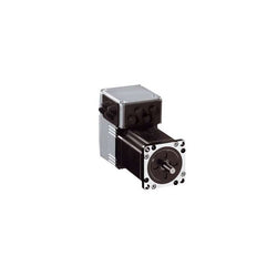
| Range of Product | Lexium integrated drive |
| Product or Component Type | Motion integrated drive |
| Device short name | ILS |
| Motor Type | 3-phase stepper motor |
| Number of motor poles | 6 |
| Phase | Single phase |
| [Us] rated supply voltage | 36 V 24 V |
| Network type | DC |
| Communication interface | RS485, Integrated |
| Length | 4.01 in (101.9 mm) |
| Winding type | Medium speed of rotation and medium torque |
| Electrical Connection | Printed circuit board connector |
| Holding brake | Without |
| Gear box type | Without |
| Nominal speed | 1000 rpm 36 V 500 rpm 24 V |
| Nominal torque | 3.98 lbf.in (0.45 N.m) |
| Holding torque | 4.51 lbf.in (0.51 N.m) |
Complementary
| Characteristic | Value(s) |
|---|---|
| Transmission Rate | 9.6, 19.2 and 38.4 kbauds |
| Mounting Support | Flange |
| Motor flange size | 2.2 in (57 mm) |
| Number of motor stacks | 1 |
| Centring collar diameter | 1.5 in (38.1 mm) |
| centring collar depth | 0.06 in (1.6 mm) |
| Number of mounting holes | 4 |
| Mounting holes diameter | 0.2 in (5.2 mm) |
| Circle diameter of the mounting holes | 2.6 in (66.6 mm) |
| Feedback type | Index pulse |
| Shaft end | Untapped |
| Second shaft | Without second shaft end |
| Shaft diameter | 0.25 in (6.35 mm) |
| Shaft length | 0.8 in (21 mm) |
| Supply voltage limits | 18â¦40 V |
| Current consumption | 3500 mA maximum |
| Associated fuse rating | 10 A |
| Input/output type | 4 signals (each be used as input or output) |
| Voltage state 0 guaranteed | -3...4.5 V |
| Voltage state 1 guaranteed | 15...30 V |
| Discrete input current | 10 mA at 24 V on/STO_A safety input 3 mA at 24 V on/STO_B safety input 2 mA at 24 V 24 V signal interface |
| Discrete output voltage | 23...25 V |
| Maximum switching current | 100 mA per output 200 mA total |
| Protection Type | Safe torque off Short circuit of the output voltage Overload of output voltage |
| Peak stall torque | 3.98 lbf.in (0.45 N.m) |
| Continuous stall torque | 3.98 lbf.in (0.45 N.m) |
| Speed feedback resolution | 20000 points/turn |
| Accuracy error | +/- 6 arc min |
| Rotor inertia | 0.1 kg.cm² |
| Maximum mechanical speed | 3000 rpm |
| Maximum radial force Fr | 24 N |
| Maximum axial force Fa | 100 N tensile force) 8.4 N force pressure) |
| Service life in hours | 20000 h bearing |
| Marking | CE |
| type of cooling | Natural convection |
| Product Weight | 2.9 lb(US) (1.3 kg) |
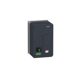
Variable speed drive, ATV320, 5.5 kW, 380…500 V, 3 phases, enclosed
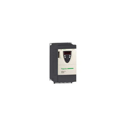
Variable Speed Drive Altivar 71-baseplate-2.2kW-3hp-480V -EMC filter-whitout graphic term.
Variable Speed Drive Altivar ATV312 - 11kW - 25kVA - 257 W - 525..600 V - 3-Phase Supply

PLC Direct is not an authorized distributor. We offer a broad range of in-stock products with minimal lead time.

integrated drive ILS with stepper motor - 24..48 V - Ethernet Powerlink - 6 A

PLC Direct is not an authorized distributor. We offer a broad range of in-stock products with minimal lead time.
variable speed drive - ATV31 - 1.5kW - 380..500V - 3-phase supply - EMC filter - IP20

Main
| Characteristic | Value(s) |
|---|---|
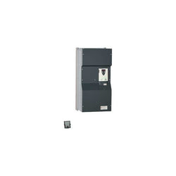
| Range of Product | Altivar 71 |
| Product or Component Type | Variable speed drive |
| Product Specific Application | Complex, high-power machines |
| Component name | ATV71 |
| Motor power kW | 315 kW, 3 phase 380...480 V |
| Maximum Horse Power Rating | 500 hp, 3 phase 380...480 V |
| Maximum motor cable length | 328.08 ft (100 m) shielded cable 656.2 ft (200 m) unshielded cable |
| power supply voltage | 380...480 V - 15...10 % |
| Phase | 3 phase |
| Line current | 444 A 480 V 3 phase 315 kW / 500 hp 555 A 380 V 3 phase 315 kW / 500 hp |
| EMC filter | Integrated |
| Assembly style | With heat sink |
| Variant | Without DC choke Reinforced version |
| Apparent power | 365.3 kVA 380 V 3 phase 315 kW / 500 hp |
| Prospective line Isc | 50 kA 3 phase |
| Nominal output current | 616 A 2.5 kHz 380 V 3 phase 315 kW / 500 hp 616 A 2.5 kHz 460 V 3 phase 315 kW / 500 hp |
| Maximum transient current | 1016 A 2 s 3 phase 315 kW / 500 hp 924 A 60 s 3 phase 315 kW / 500 hp |
| Output frequency | 0.1â¦500 Hz |
| Nominal switching frequency | 2.5 kHz |
| Switching frequency | 2.5...8 kHz adjustable 2.5...8 kHz with derating factor |
| Asynchronous motor control profile | Voltage/frequency ratio (2 or 5 points) ENA (Energy adaptation) system for unbalanced loads Flux vector control (FVC) with sensor (current vector) Sensorless flux vector control (SFVC) (voltage or current vector) |
| Type of polarization | No impedance Modbus |
Complementary
| Characteristic | Value(s) |
|---|---|
| Product destination | Asynchronous motors Synchronous motors |
| power supply voltage limits | 323â¦528 V |
| power supply frequency | 50...60 Hz - 5...5 % |
| power supply frequency limits | 47.5...63 Hz |
| Speed range | 1â¦100 asynchronous motor in open-loop mode, without speed feedback 1â¦1000 asynchronous motor in closed-loop mode with encoder feedback 1â¦50 synchronous motor in open-loop mode, without speed feedback |
| Speed accuracy | +/- 0.01 % of nominal speed in closed-loop mode with encoder feedback 0.2 Tn to Tn +/- 10 % of nominal slip without speed feedback 0.2 Tn to Tn |
| Torque accuracy | +/- 15 % in open-loop mode, without speed feedback +/- 5 % in closed-loop mode with encoder feedback |
| Transient overtorque | 170 % +/- 10 % 60 s every 10 minutes 220 % +/- 10 % 2 s |
| Braking torque | <= 150 % with braking or hoist resistor 30 % without braking resistor |
| Synchronous motor control profile | Vector control without speed feedback |
| Regulation loop | Adjustable PI regulator |
| Motor slip compensation | Automatic whatever the load Not available in voltage/frequency ratio (2 or 5 points) Suppressable Adjustable |
| diagnostic | 1 LED (red) for drive voltage |
| Output voltage | <= power supply voltage |
| Insulation | Electrical between power and control |
| type of cable for mounting in an enclosure | With a NEMA Type1 kit 3 UL 508 cable 104 °F (40 °C), copper 75 °C / PVC With an IP21 or an IP31 kit 3 IEC cable 104 °F (40 °C), copper 70 °C / PVC Without mounting kit 1 IEC cable 113 °F (45 °C), copper 70 °C / PVC Without mounting kit 1 IEC cable 113 °F (45 °C), copper 90 °C / XLPE/EPR |
| Electrical connection | Terminal 2.5 mm², AWG 14 AI1-/AI1+, AI2, AO1, R1A, R1B, R1C, R2A, R2B, LI1...LI6, PWR) Terminal 4 x 185 mm² L1/R, L2/S, L3/T, U/T1, V/T2, W/T3) Terminal 8 x 185 mm² PC/-, PO, PA/+) |
| Tightening torque | 5.3 lbf.in (0.6 N.m) AI1-/AI1+, AI2, AO1, R1A, R1B, R1C, R2A, R2B, LI1...LI6, PWR) 362.9 lbf.in (41 N.m), 360 lb.in PC/-, PO, PA/+) 362.9 lbf.in (41 N.m), 360 lb.in L1/R, L2/S, L3/T, U/T1, V/T2, W/T3) |
| Supply | Internal supply for reference potentiometer (1 to 10 kOhm) 10.5 V DC +/- 5 %, <10 mA overload and short-circuit protection Internal supply 24 V DC 21â¦27 V), <200 mA overload and short-circuit protection |
| Analogue input number | 2 |
| Analogue input type | AI1-/Al1+ bipolar differential voltage +/- 10 V DC 24 V max 11 bits + sign AI2 software-configurable current 0...20 mA 242 Ohm 11 bits AI2 software-configurable voltage 0...10 V DC 24 V max 30000 Ohm 11 bits |
| input sampling time | 2 ms +/- 0.5 ms AI1-/Al1+) - analog 2 ms +/- 0.5 ms Al2) - analog 2 ms +/- 0.5 ms LI1...LI5) - discrete 2 ms +/- 0.5 ms LI6)if configured as logic input - discrete |
| Response time | <= 100 ms in STO (Safe Torque Off) AO1 2 ms +/- 0.5 ms analog R1A, R1B, R1C 7 ms +/- 0.5 ms discrete R2A, R2B 7 ms +/- 0.5 ms discrete |
| absolute accuracy precision | +/- 0.6 % AI1-/Al1+) for a temperature variation 60 °C +/- 0.6 % AI2) for a temperature variation 60 °C +/- 1 % AO1) for a temperature variation 60 °C |
| Linearity error | +/- 0.15 % of maximum value AI1-/Al1+, AI2) +/- 0.2 % AO1) |
| Analogue output number | 1 |
| Analogue output type | AO1 software-configurable logic output 10 V 20 mA AO1 software-configurable current 0...20 mA 500 Ohm 10 bits AO1 software-configurable voltage 0...10 V DC 470 Ohm 10 bits |
| Discrete output number | 2 |
| Discrete output type | Configurable relay logic R1A, R1B, R1C) NO/NC - 100000 cycles Configurable relay logic R2A, R2B) NO - 100000 cycles |
| Minimum switching current | 3 mA 24 V DC configurable relay logic |
| Maximum switching current | R1, R2 2 A 250 V AC inductive, cos phi = 0.4 R1, R2 2 A 30 V DC inductive, cos phi = 0.4 R1, R2 5 A 250 V AC resistive, cos phi = 1 R1, R2 5 A 30 V DC resistive, cos phi = 1 |
| Discrete input number | 7 |
| Discrete input type | LI1...LI5 programmable 24 V DC level 1 PLC 3500 Ohm LI6 switch-configurable 24 V DC level 1 PLC 3500 Ohm LI6 switch-configurable PTC probe 0â¦6 1500 Ohm PWR safety input 24 V DC 1500 Ohm ISO 13849-1 level d |
| Discrete input logic | Negative logic (sink) LI1...LI5), > 16 V, < 10 V Positive logic (source) LI1...LI5), < 5 V, > 11 V Negative logic (sink) LI6)if configured as logic input, > 16 V, < 10 V Positive logic (source) LI6)if configured as logic input, < 5 V, > 11 V |
| Acceleration and deceleration ramps | S, U or customized Linear adjustable separately from 0.01 to 9000 s Automatic adaptation of ramp if braking capacity exceeded, by using resistor |
| Braking to standstill | By DC injection |
| Protection type | Against exceeding limit speed drive Against input phase loss drive Break on the control circuit drive Input phase breaks drive Line supply overvoltage drive Line supply undervoltage drive Overcurrent between output phases and earth drive Overheating protection drive Overvoltages on the DC bus drive Short-circuit between motor phases drive Thermal protection drive Motor phase break motor Power removal motor Thermal protection motor |
| Insulation resistance | > 1 mOhm 500 V DC for 1 minute to earth |
| Frequency resolution | Analog input 0.024/50 Hz Display unit 0.1 Hz |
| Communication Port Protocol | CANopen Modbus |
| Connector type | 1 RJ45 on front face)Modbus 1 RJ45 on terminal)Modbus Male SUB-D 9 on RJ45CANopen |
| Physical interface | 2-wire RS 485 Modbus |
| Transmission frame | RTU Modbus |
| Transmission rate | 4800 bps, 9600 bps, 19200 bps, 38.4 Kbps Modbus on terminal 9600 bps, 19200 bps Modbus on front face 20 kbps, 50 kbps, 125 kbps, 250 kbps, 500 kbps, 1 Mbps CANopen |
| Data format | 8 bits, 1 stop, even parity Modbus on front face 8 bits, odd even or no configurable parity Modbus on terminal |
| Number of addresses | 1â¦127 CANopen 1â¦247 Modbus |
| Method of access | Slave CANopen |
| Marking | CE |
| Operating position | Vertical +/- 10 degree |
| Height | 54.7 in (1390 mm) |
| Depth | 14.8 in (377 mm) |
| Width | 35.04 in (890 mm) |
| Product Weight | 474.0 lb(US) (215 kg) |
| Option card | Communication card CC-Link Controller inside programmable card Communication card DeviceNet Communication card EtherNet/IP Communication card Fipio I/O extension card Communication card Interbus-S Interface card for encoder Communication card Modbus Plus Communication card Modbus TCP Communication card Modbus/Uni-Telway Overhead crane card Communication card Profibus DP Communication card Profibus DP V1 |

Main
| Characteristic | Value(s) |
|---|---|
| Range of Product | Altivar |
| Product or Component Type | Variable speed drive |
| Product Specific Application | Simple machine |
| Component name | ATV31 |
| Assembly style | With heat sink |
| EMC filter | Without EMC filter |
| [Us] rated supply voltage | 200...240 V - 5...5 % |
| Supply frequency | 50...60 Hz - 5...5 % |
| Phase | 3 phase |
| Motor power kW | 1.1 kW 4 kHz |
| Maximum Horse Power Rating | 1.5 hp 4 kHz |
| Line current | 7.4 A 240 V 8.5 A 200 V, Isc = 1 kA |
| Apparent power | 3 kVA |
| Prospective line Isc | 1 kA |
| Nominal output current | 6.9 A 4 kHz |
| Maximum transient current | 10.4 A 60 s |
| Power dissipation in W | 71 W at nominal load |
| Asynchronous motor control profile | Factory set : constant torque Sensorless flux vector control with PWM type motor control signal |
| Analogue input number | 3 |
Complementary
| Characteristic | Value(s) |
|---|---|
| Product destination | Asynchronous motors |
| Supply voltage limits | 170â¦264 V |
| Network Frequency | 47.5...63 Hz |
| Output frequency | 0.0005â¦0.5 kHz |
| Nominal switching frequency | 4 kHz |
| Switching frequency | 2...16 kHz adjustable |
| Speed range | 1â¦50 |
| Transient overtorque | 150â¦170 % of nominal motor torque |
| Braking torque | <= 150 % 60 s with braking resistor 100 % with braking resistor continuously 150 % without braking resistor |
| Regulation loop | Frequency PI regulator |
| Motor slip compensation | Suppressable Adjustable Automatic whatever the load |
| Output voltage | <= power supply voltage |
| Electrical connection | Al1, Al2, Al3, AOV, AOC, R1A, R1B, R1C, R2A, R2B, LI1...LI6 terminal 0.004 in² (2.5 mm²) AWG 14 L1, L2, L3, U, V, W, PA, PB, PA/+, PC/- terminal 0.004 in² (2.5 mm²) AWG 14 |
| Tightening torque | Al1, Al2, Al3, AOV, AOC, R1A, R1B, R1C, R2A, R2B, LI1...LI6 5.3 lbf.in (0.6 N.m) L1, L2, L3, U, V, W, PA, PB, PA/+, PC/- 7.08 lbf.in (0.8 N.m) |
| Insulation | Electrical between power and control |
| Supply | Internal supply for logic inputs 19...30 V 100 mA overload and short-circuit protection Internal supply for reference potentiometer (2.2 to 10 kOhm) 10...10.8 V 10 mA overload and short-circuit protection |
| Analogue input type | AI3 configurable current 0...20 mA 250 Ohm AI1 configurable voltage 0...10 V 30 V max 30000 Ohm AI2 configurable voltage +/- 10 V 30 V max 30000 Ohm |
| Sampling duration | LI1...LI6 4 ms discrete AI1, AI2, AI3 8 ms analog |
| Response time | AOV, AOC 8 ms analog R1A, R1B, R1C, R2A, R2B 8 ms discrete |
| Linearity error | +/- 0.2 % output |
| Analogue output number | 2 |
| Analogue output type | AOC configurable current 0...20 mA 800 Ohm 8 bits AOV configurable voltage 0...10 V 470 Ohm 8 bits |
| Discrete input logic | Positive logic (source) LI1...LI6), < 5 V, > 11 V Logic input not wired LI1...LI4), < 13 V Negative logic (source) LI1...LI6), > 19 V |
| Discrete output number | 2 |
| Discrete output type | Configurable relay logic R1A, R1B, R1C) 1 NO + 1 NC - 100000 cycles Configurable relay logic R2A, R2B) NC - 100000 cycles |
| Minimum switching current | R1-R2 10 mA 5 V DC |
| Maximum switching current | R1-R2 2 A 250 V AC inductive, cos phi = 0.4 7 ms R1-R2 2 A 30 V DC inductive, cos phi = 0.4 7 ms R1-R2 5 A 250 V AC resistive, cos phi = 1 0 ms R1-R2 5 A 30 V DC resistive, cos phi = 1 0 ms |
| Discrete input number | 6 |
| Discrete input type | LI1...LI6) programmable 24 V, 0â¦100 mA PLC 3500 Ohm |
| Acceleration and deceleration ramps | S, U or customized Linear adjustable separately from 0.1 to 999.9 s |
| Braking to standstill | By DC injection |
| Protection type | Input phase breaks drive Line supply overvoltage and undervoltage safety circuits drive Line supply phase loss safety function, for three phases supply drive Motor phase breaks drive Overcurrent between output phases and earth (on power up only) drive Overheating protection drive Short-circuit between motor phases drive Thermal protection motor |
| Insulation resistance | >= 500 mOhm 500 V DC for 1 minute |
| Display type | 1 LED Red)drive voltage Four 7-segment display unitsCANopen bus status |
| Time constant | 5 ms for reference change |
| Frequency resolution | Display unit 0.1 Hz Analog input 0.1...100 Hz |
| Connector type | 1 RJ45 CANopen via VW3 CANTAP2 adaptor 1 RJ45 Modbus |
| Physical interface | RS485 multidrop serial link CANopen via VW3 CANTAP2 adaptor RS485 multidrop serial link Modbus |
| Transmission frame | RTU CANopen via VW3 CANTAP2 adaptor RTU Modbus |
| Transmission Rate | 10, 20, 50, 125, 250, 500 kbps or 1 Mbps CANopen via VW3 CANTAP2 adaptor 4800, 9600 or 19200 bps Modbus |
| Number of addresses | 1â¦127 CANopen via VW3 CANTAP2 adaptor 1â¦247 Modbus |
| Number of drive | 127 CANopen via VW3 CANTAP2 adaptor 31 Modbus |
| Marking | CE |
| Operating position | Vertical +/- 10 degree |
| Product Weight | 3.7 lb(US) (1.7 kg) |

Main
| Characteristic | Value(s) |
|---|---|
| Range of Product | Lexium integrated drive |
| Product or Component Type | Motion integrated drive |
| Device short name | ILS |
| Motor Type | 3-phase stepper motor |
| Number of motor poles | 6 |
| Phase | Single phase |
| [Us] rated supply voltage | 24 V 48 V |
| Network type | DC |
| Communication interface | DeviceNet, Integrated |
| Length | 5.5 in (138.9 mm) |
| Winding type | Medium speed of rotation and medium torque |
| Electrical Connection | Printed circuit board connector |
| Holding brake | Without |
| Gear box type | Without |
| Nominal speed | 300 rpm 24 V 600 rpm 48 V |
| Nominal torque | 13.3 lbf.in (1.5 N.m) |
| Holding torque | 13.3 lbf.in (1.5 N.m) |
Complementary
| Characteristic | Value(s) |
|---|---|
| Transmission Rate | 125, 250, 500 kbauds |
| Mounting Support | Flange |
| Motor flange size | 2.2 in (57 mm) |
| Number of motor stacks | 3 |
| Centring collar diameter | 1.5 in (38.1 mm) |
| centring collar depth | 0.06 in (1.6 mm) |
| Number of mounting holes | 4 |
| Mounting holes diameter | 0.2 in (5.2 mm) |
| Circle diameter of the mounting holes | 2.6 in (66.6 mm) |
| Feedback type | Index pulse |
| Shaft end | Untapped |
| Second shaft | Without second shaft end |
| Shaft diameter | 0.3 in (8 mm) |
| Shaft length | 0.8 in (21 mm) |
| Supply voltage limits | 18â¦55 V |
| Current consumption | 3500 mA maximum continuous |
| Associated fuse rating | 16 A |
| Commissioning interface | RS485 Modbus TCP 9.6, 19.2 and 38.4 kbauds) |
| Input/output type | 4 signals (each be used as input or output) |
| Voltage state 0 guaranteed | -3...4.5 V |
| Voltage state 1 guaranteed | 15...30 V |
| Discrete input current | 10 mA at 24 V safety input 2 mA at 24 V 24 V signal interface |
| Discrete output voltage | 23...25 V |
| Maximum switching current | 100 mA per output 200 mA total |
| Protection Type | Overload of output voltage Safe torque off Short circuit of the output voltage |
| Peak stall torque | 13.3 lbf.in (1.5 N.m) |
| Continuous stall torque | 13.3 lbf.in (1.5 N.m) |
| Speed feedback resolution | 20000 points/turn |
| Accuracy error | +/- 6 arc min |
| Rotor inertia | 0.38 kg.cm² |
| Maximum mechanical speed | 3000 rpm |
| Maximum radial force Fr | 50 N |
| Maximum axial force Fa | 100 N tensile force) 8.4 N force pressure) |
| Service life in hours | 20000 h bearing |
| Marking | CE |
| type of cooling | Natural convection |
| Product Weight | 4.4 lb(US) (2 kg) |