
 1 year warranty


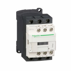
TeSys D contactor 3P 12A AC-3 up to 440V coil 100-250V AC/DC
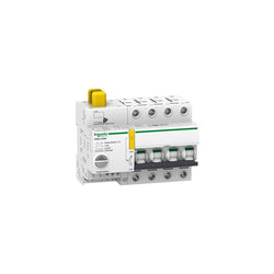
It is a 4P circuit breaker with protected poles, 25 A rated current and D tripping curve. As circuit breaker, its breaking capacity, according to IEC/EN 60947-2, is 20kA at 220VAC to 240VAC, and 10kA at 380VAC to 415VAC. It allows to execute remote control, to indicate the state of the control circuit and circuit breaker state information, to connect it to the Acti9 Smartlink thanks to the prefabricated cables.
Main
| Characteristic | Value(s) |
|---|---|
| Device application | Distribution Control |
| Range | Acti9 |
| product name | Reflex iC60 |
| Device short name | Reflex iC60N |
| Product or component type | Integrated control circuit breaker |
| Poles description | 4P |
| Number of protected poles | 4 |
| Network type | AC |
| Trip unit technology | Thermal-magnetic |
| Curve code | D |
Complementary
| Characteristic | Value(s) |
|---|---|
| [In] rated current | 25 A |
| Network frequency | 50/60 Hz |
| Breaking capacity code | N |
| Breaking capacity | 20 kA Icu at 220...240 V AC 50/60 Hz conforming to EN/IEC 60947-2 10 kA Icu at 380...415 V AC 50/60 Hz conforming to EN/IEC 60947-2 |
| [Ui] rated insulation voltage | 500 V AC |
| Contact position indicator | Yes |
| control type | Remote control by continuous command Toggle Remote control by pulse ON/OFF button |
| Control signal type | Maintained very low voltage Maintained Impulse |
| Local signalling | Red LED: fault Flashing LED: device tripped Flashing LED: device overheat Flashing LED: device ready Green LED: device ON |
| [Uc] control circuit voltage | 230 V AC 50/60 Hz 24 V AC 50/60 Hz 48 V AC 50/60 Hz 24 V DC 48 V DC |
| [Us] rated supply voltage | 230 V AC at 50/60 Hz |
| Mounting mode | Fixed |
| Mounting support | 35 mm symmetrical DIN rail |
| 9 mm pitches | 13 |
| Height | 84 mm |
| Width | 117 mm |
| Depth | 77 mm |
| Colour | White |
| Mechanical durability | 50000 cycles |
| Electrical durability | AC-1: 50000 cycles AC 50 Hz |
| Provision for padlocking | Padlockable |
| Locking options description | Padlock in OFF position |
| Earth-leakage protection | Separate block |
| Product compatibility | With PLC |

Motor circuit breaker, TeSys GV3, 3P, 73 A, magnetic, rotary handle, EverLink terminals, for contactor assembly
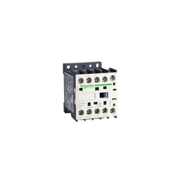
TeSys K contactor, 4 poles (4NO), for non-inductive load control applications up to 20A/690V AC-1. It provides a 230-240V 50/60Hz AC coil, without built-in auxiliary contact, connection by screw clamp terminals. For operating rates until 600 cycles/hour and environments until 50°C, it procures reliability and durability to standard applications. Very compact (45mm width), DIN-rail mounting or screw fixing. Multi standards certified (IEC, UL, CSA, CCC, EAC).
Main
| Characteristic | Value(s) |
|---|---|
| Range | TeSys |
| Product or Component Type | Contactor |
| Device short name | LC1K |
| Device Application | Control |
| Contactor application | Resistive load |
Complementary
| Characteristic | Value(s) |
|---|---|
| Utilisation category | AC-1 |
| Poles description | 4P |
| power pole contact composition | 4 NO |
| [Ue] rated operational voltage | Power circuit <= 690 V AC <= 400 Hz Signalling circuit <= 690 V AC <= 400 Hz |
| [Ie] rated operational current | 20 A (at <140 °F (60 °C)) at <= 690 V AC AC-1 for power circuit |
| Control circuit type | AC 50/60 Hz |
| [Uc] control circuit voltage | 230...240 V AC 50/60 Hz |
| [Uimp] rated impulse withstand voltage | 8 kV |
| Overvoltage category | III |
| [Ith] conventional free air thermal current | 20 A (at 140 °F (60 °C)) for power circuit 10 A (at 122 °F (50 °C)) for signalling circuit |
| Irms rated making capacity | 110 A AC for power circuit conforming to IEC 60947 |
| Rated breaking capacity | 110 A at 220...230 V conforming to IEC 60947 110 A at 380...400 V conforming to IEC 60947 110 A at 415 V conforming to IEC 60947 110 A at 440 V conforming to IEC 60947 80 A at 500 V conforming to IEC 60947 70 A at 660...690 V conforming to IEC 60947 |
| [Icw] rated short-time withstand current | 90 A 122 °F (50 °C) - 1 s for power circuit 85 A 122 °F (50 °C) - 5 s for power circuit 80 A 122 °F (50 °C) - 10 s for power circuit 60 A 122 °F (50 °C) - 30 s for power circuit 45 A 122 °F (50 °C) - 1 min for power circuit 40 A 122 °F (50 °C) - 3 min for power circuit 20 A 122 °F (50 °C) - >= 15 min for power circuit |
| Associated fuse rating | 25 A gG at <= 440 V for power circuit 25 A aM for power circuit |
| Average impedance | 3 mOhm - Ith 20 A 50 Hz for power circuit |
| [Ui] rated insulation voltage | Power circuit 600 V UL 508 Power circuit 690 V IEC 60947-4-1 Power circuit 600 V CSA C22.2 No 14 |
| Inrush power in VA | 30 VA (at 68 °F (20 °C)) |
| Hold-in power consumption in VA | 4.5 VA (at 68 °F (20 °C)) |
| Heat dissipation | 1.3 W |
| Control circuit voltage limits | Operational: 0.8...1.15 Uc (at <122 °F (50 °C)) Drop-out: >= 0.20 Uc (at <122 °F (50 °C)) |
| Connections - terminals | screw clamp terminals 1 0.002â¦0.006 in² (1.5â¦4 mm²)solid screw clamp terminals 1 0.001â¦0.006 in² (0.75â¦4 mm²)flexible without cable end screw clamp terminals 1 0.0005â¦0.004 in² (0.34â¦2.5 mm²)flexible with cable end screw clamp terminals 2 0.002â¦0.006 in² (1.5â¦4 mm²)solid screw clamp terminals 2 0.001â¦0.006 in² (0.75â¦4 mm²)flexible without cable end screw clamp terminals 2 0.0005â¦0.002 in² (0.34â¦1.5 mm²)flexible with cable end |
| Maximum operating rate | 3600 cyc/h |
| Signalling circuit frequency | <= 400 Hz |
| Mounting Support | Rail Plate |
| Tightening torque | 7.08â¦11.5 lbf.in (0.8â¦1.3 N.m) screw clamp terminals Philips No 2 7.08â¦11.5 lbf.in (0.8â¦1.3 N.m) screw clamp terminals flat à 6 mm 7.08â¦11.5 lbf.in (0.8â¦1.3 N.m) screw clamp terminals pozidriv No 2 |
| Operating time | 10...20 ms coil de-energisation and NO opening 10...20 ms coil energisation and NO closing |
| Safety reliability level | B10d = 1369863 cycles contactor with nominal load EN/ISO 13849-1 B10d = 20000000 cycles contactor with mechanical load EN/ISO 13849-1 |
| Mechanical durability | 10 Mcycles |
| Electrical durability | 0.16 Mcycles 20 A AC-1 <= 690 V |
| Mechanical robustness | Shocks contactor closed, on X axis10 Gn for 11 ms IEC 60068-2-27 Shocks contactor closed, on Y axis15 Gn for 11 ms IEC 60068-2-27 Shocks contactor closed, on Z axis15 Gn for 11 ms IEC 60068-2-27 Shocks contactor opened, on X axis6 Gn for 11 ms IEC 60068-2-27 Shocks contactor opened, on Y axis10 Gn for 11 ms IEC 60068-2-27 Shocks contactor opened, on Z axis10 Gn for 11 ms IEC 60068-2-27 Vibrations contactor closed4 Gn, 5...300 Hz IEC 60068-2-6 Vibrations contactor opened2 Gn, 5...300 Hz IEC 60068-2-6 |
| Height | 2.3 in (58 mm) |
| Width | 1.8 in (45 mm) |
| Depth | 2.2 in (57 mm) |
| Product Weight | 0.40 lb(US) (0.18 kg) |


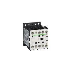
TeSys K contactor - 3P - AC-3 <= 440 V 6 A - 1 NO aux. - 220...230 V AC coil

TeSys Deca contactor, 3 poles (3NO), for motor control applications up to 18A/690V AC-3/3e (7.5kW@400V). It provides a 220V DC coil with transient suppressor module, 1NO+1NC built-in auxiliary contacts (NC mirror certified), connection by screw clamp terminals. For operating rates until 3600 cycles/hour and environments until 60°C, it procures high reliability and durability. Compact (45mm width), DIN-rail mounting or screw fixing. Multi standards certified (IEC, UL, CSA, CCC, EAC, Marine), Green Premium compliant (RoHS/REACh).
Main
| Characteristic | Value(s) |
|---|---|
| Range of Product | TeSys Deca |
| Product or Component Type | Contactor |
| Device short name | LC1D |
| Contactor application | Resistive load Motor control |
| Utilisation category | AC-3 AC-4 AC-1 AC-3e |
| Poles description | 3P |
| [Ue] rated operational voltage | Power circuit <= 690 V AC 25...400 Hz Power circuit <= 300 V DC |
| [Ie] rated operational current | 18 A (at <140 °F (60 °C)) at <= 440 V AC AC-3 for power circuit 32 A (at <140 °F (60 °C)) at <= 440 V AC AC-1 for power circuit 18 A (at <140 °F (60 °C)) at <= 440 V AC AC-3e for power circuit |
| [Uc] control circuit voltage | 220 V DC |
Complementary
| Characteristic | Value(s) |
|---|---|
| Motor power kW | 4 kW at 220...230 V AC 50/60 Hz (AC-3) 7.5 kW at 380...400 V AC 50/60 Hz (AC-3) 9 kW at 415...440 V AC 50/60 Hz (AC-3) 10 kW at 500 V AC 50/60 Hz (AC-3) 10 kW at 660...690 V AC 50/60 Hz (AC-3) 4 kW at 400 V AC 50/60 Hz (AC-4) 4 kW at 220...230 V AC 50/60 Hz (AC-3e) 7.5 kW at 380...400 V AC 50/60 Hz (AC-3e) 9 kW at 415...440 V AC 50/60 Hz (AC-3e) 10 kW at 500 V AC 50/60 Hz (AC-3e) 10 kW at 660...690 V AC 50/60 Hz (AC-3e) |
| Maximum Horse Power Rating | 1 hp at 115 V AC 50/60 Hz for 1 phase motors 3 hp at 230/240 V AC 50/60 Hz for 1 phase motors 5 hp at 200/208 V AC 50/60 Hz for 3 phase motors 5 hp at 230/240 V AC 50/60 Hz for 3 phase motors 10 hp at 460/480 V AC 50/60 Hz for 3 phase motors 15 hp at 575/600 V AC 50/60 Hz for 3 phase motors |
| Compatibility code | LC1D |
| Pole contact composition | 3 NO |
| Protective cover | With |
| [Ith] conventional free air thermal current | 10 A (at 140 °F (60 °C)) for signalling circuit 32 A (at 140 °F (60 °C)) for power circuit |
| Irms rated making capacity | 140 A AC for signalling circuit conforming to IEC 60947-5-1 250 A DC for signalling circuit conforming to IEC 60947-5-1 300 A at 440 V for power circuit conforming to IEC 60947 |
| Rated breaking capacity | 300 A at 440 V for power circuit conforming to IEC 60947 |
| [Icw] rated short-time withstand current | 145 A 104 °F (40 °C) - 10 s for power circuit 240 A 104 °F (40 °C) - 1 s for power circuit 40 A 104 °F (40 °C) - 10 min for power circuit 84 A 104 °F (40 °C) - 1 min for power circuit 100 A - 1 s for signalling circuit 120 A - 500 ms for signalling circuit 140 A - 100 ms for signalling circuit |
| Associated fuse rating | 10 A gG for signalling circuit conforming to IEC 60947-5-1 50 A gG at <= 690 V coordination type 1 for power circuit 35 A gG at <= 690 V coordination type 2 for power circuit |
| Average impedance | 2.5 mOhm - Ith 32 A 50 Hz for power circuit |
| Power dissipation per pole | 2.5 W AC-1 0.8 W AC-3 0.8 W AC-3e |
| [Ui] rated insulation voltage | Power circuit 690 V IEC 60947-4-1 Power circuit 600 V CSA Power circuit 600 V UL Signalling circuit 690 V IEC 60947-1 Signalling circuit 600 V CSA Signalling circuit 600 V UL |
| Overvoltage category | III |
| pollution degree | 3 |
| [Uimp] rated impulse withstand voltage | 6 kV IEC 60947 |
| Safety reliability level | B10d = 1369863 cycles contactor with nominal load EN/ISO 13849-1 B10d = 20000000 cycles contactor with mechanical load EN/ISO 13849-1 |
| Mechanical durability | 30 Mcycles |
| Electrical durability | 1.65 Mcycles 18 A AC-3 <= 440 V 1 Mcycles 32 A AC-1 <= 440 V 1.65 Mcycles 18 A AC-3e <= 440 V |
| Control circuit type | DC standard |
| Coil technology | With integral suppression device |
| Control circuit voltage limits | 0.1...0.25 Uc (-40â¦158 °F (-40â¦70 °C)):drop-out DC 0.7...1.25 Uc (-40â¦140 °F (-40â¦60 °C)):operational DC 1...1.25 Uc (140â¦158 °F (60â¦70 °C)):operational DC |
| Inrush power in W | 5.4 W 68 °F (20 °C)) |
| Hold-in power consumption in W | 5.4 W 68 °F (20 °C) |
| Operating time | 63 ±15 % ms closing 20 ±20 % ms opening |
| Time constant | 28 ms |
| Maximum operating rate | 3600 cyc/h at 60 °C |
| Connections - terminals | Control circuit: screw clamp terminals 1 0.002â¦0.006 in² (1â¦4 mm²) - cable stiffness: flexible without cable end Control circuit: screw clamp terminals 2 0.002â¦0.006 in² (1â¦4 mm²) - cable stiffness: flexible without cable end Control circuit: screw clamp terminals 1 0.002â¦0.006 in² (1â¦4 mm²) - cable stiffness: flexible with cable end Control circuit: screw clamp terminals 2 0.002â¦0.004 in² (1â¦2.5 mm²) - cable stiffness: flexible with cable end Control circuit: screw clamp terminals 1 0.002â¦0.006 in² (1â¦4 mm²) - cable stiffness: solid without cable end Control circuit: screw clamp terminals 2 0.002â¦0.006 in² (1â¦4 mm²) - cable stiffness: solid without cable end Power circuit: screw clamp terminals 1 0.002â¦0.009 in² (1.5â¦6 mm²) - cable stiffness: flexible without cable end Power circuit: screw clamp terminals 2 0.002â¦0.009 in² (1.5â¦6 mm²) - cable stiffness: flexible without cable end Power circuit: screw clamp terminals 1 0.002â¦0.009 in² (1â¦6 mm²) - cable stiffness: flexible with cable end Power circuit: screw clamp terminals 2 0.002â¦0.006 in² (1â¦4 mm²) - cable stiffness: flexible with cable end Power circuit: screw clamp terminals 1 0.002â¦0.009 in² (1.5â¦6 mm²) - cable stiffness: solid without cable end Power circuit: screw clamp terminals 2 0.002â¦0.009 in² (1.5â¦6 mm²) - cable stiffness: solid without cable end |
| Tightening torque | Power circuit 15.05 lbf.in (1.7 N.m) screw clamp terminals flat à 6 mm Power circuit 15.05 lbf.in (1.7 N.m) screw clamp terminals Philips No 2 Control circuit 15.05 lbf.in (1.7 N.m) screw clamp terminals flat à 6 mm Control circuit 15.05 lbf.in (1.7 N.m) screw clamp terminals Philips No 2 Control circuit 15.05 lbf.in (1.7 N.m) screw clamp terminals pozidriv No 2 Power circuit 15.05 lbf.in (1.7 N.m) screw clamp terminals pozidriv No 2 |
| Auxiliary contact composition | 1 NO + 1 NC |
| Auxiliary contacts type | Mechanically linked 1 NO + 1 NC IEC 60947-5-1 Mirror contact 1 NC IEC 60947-4-1 |
| Signalling circuit frequency | 25...400 Hz |
| Minimum switching voltage | 17 V for signalling circuit |
| Minimum switching current | 5 mA for signalling circuit |
| Insulation resistance | > 10 MOhm for signalling circuit |
| Non-overlap time | 1.5 ms on de-energisation between NC and NO contact 1.5 ms on energisation between NC and NO contact |
| Mounting Support | Rail Plate |
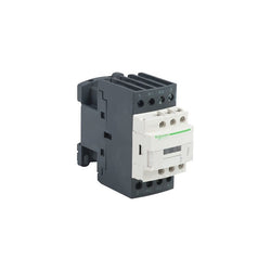
TeSys D contactor - 4P(2 NO + 2 NC) - AC-1 - <= 440 V 40 A - 110 V AC coil
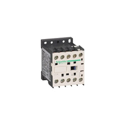
TeSys K contactor, 3P(3NO) for category AC-3 motor control applications up to 9A @440V. It is fully compliant with railway standards. It procures high reliability and durability with 30 Mcycles mechanical durability and 1.3 Mcycles electrical durability. It provides IP20 protection confirming to VDE 0106. It can cover up to 50°C operation temperature under 2000m altitude without derating . Designed for demanding applications with maximum operating rates up to 3600 cycles/hr. The dimension is 58mm x 45mm x 57mm (H x W x D), mounting on rail or plate. Multi international standards certified, Green Premium product (RoHS/REACh).
Main
| Characteristic | Value(s) |
|---|---|
| Range | TeSys |
| Product or component type | Contactor |
| Device short name | LC1K |
| Device application | Control |
| Contactor application | Resistive load Motor control |
Complementary
| Characteristic | Value(s) |
|---|---|
| Utilisation category | AC-3 AC-3e AC-1 AC-4 |
| Poles description | 3P |
| power pole contact composition | 3 NO |
| [Ue] rated operational voltage | Power circuit: <= 690 V AC <= 400 Hz Signalling circuit: <= 690 V AC <= 400 Hz |
| [Ie] rated operational current | 9 A (at <60 °C) at <= 440 V AC AC-3 for power circuit 9 A (at <60 °C) at <= 440 V AC AC-3e for power circuit 20 A (at <60 °C) at <= 690 V AC AC-1 for power circuit |
| Control circuit type | DC low consumption |
| [Uc] control circuit voltage | 24 V DC |
| Motor power kW | 2.2 kW at 220...230 V AC 50/60 Hz AC-3 4 kW at 380...415 V AC 50/60 Hz AC-3 4 kW at 440/690 V AC 50/60 Hz AC-3 2.2 kW at 220...230 V AC 50/60 Hz AC-3e 4 kW at 380...415 V AC 50/60 Hz AC-3e 4 kW at 440/690 V AC 50/60 Hz AC-3e 2.2 kW at 220...230 V AC 50/60 Hz AC-4 4 kW at 380...415 V AC 50/60 Hz AC-4 4 kW at 440/690 V AC 50/60 Hz AC-4 |
| Auxiliary contact composition | 1 NC |
| [Uimp] rated impulse withstand voltage | 8 kV |
| Overvoltage category | III |
| [Ith] conventional free air thermal current | 20 A (at 60 °C) for power circuit 10 A (at 50 °C) for signalling circuit |
| Irms rated making capacity | 110 A AC for power circuit conforming to IEC 60947 110 A AC for signalling circuit conforming to IEC 60947 |
| Rated breaking capacity | 110 A at 220...230 V conforming to IEC 60947 110 A at 380...400 V conforming to IEC 60947 110 A at 415 V conforming to IEC 60947 110 A at 440 V conforming to IEC 60947 80 A at 500 V conforming to IEC 60947 70 A at 660...690 V conforming to IEC 60947 |
| [Icw] rated short-time withstand current | 90 A 50 °C - 1 s for power circuit 85 A 50 °C - 5 s for power circuit 80 A 50 °C - 10 s for power circuit 60 A 50 °C - 30 s for power circuit 45 A 50 °C - 1 min for power circuit 40 A 50 °C - 3 min for power circuit 20 A 50 °C - >= 15 min for power circuit 80 A - 1 s for signalling circuit 90 A - 500 ms for signalling circuit 110 A - 100 ms for signalling circuit |
| Associated fuse rating | 25 A gG at <= 440 V for power circuit 10 A gG for signalling circuit conforming to IEC 60947 10 A gG for signalling circuit conforming to VDE 0660 |
| Average impedance | 3 mOhm - Ith 20 A 50 Hz for power circuit |
| [Ui] rated insulation voltage | Power circuit: 690 V conforming to IEC 60947-4-1 Signalling circuit: 690 V conforming to IEC 60947-4-1 Signalling circuit: 690 V conforming to IEC 60947-5-1 Power circuit: 750 V conforming to VDE 0110 group C Power circuit: 690 V conforming to BS 5424 Power circuit: 690 V conforming to NF C 20-040 |
| safety cover | With |
| Insulation resistance | > 10 MOhm for signalling circuit |
| Inrush power in W | 1.8 W (at 20 °C) |
| Hold-in power consumption in W | 1.8 W at 20 °C |
| Heat dissipation | 1.8 W |
| Control circuit voltage limits | Operational: 0.7...1.3 Uc (at <50 °C) Drop-out: >= 0.10 Uc (at <50 °C) |
| Connections - terminals | Power circuit: lugs-ring terminals (external diameter: 7 mm) |
| Maximum operating rate | 3600 cyc/h |
| Coil technology | With integral suppression device |
| Auxiliary contacts type | type instantaneous 1 NC |
| Signalling circuit frequency | <= 400 Hz |
| Minimum switching current | 5 mA for signalling circuit |
| Minimum switching voltage | 17 V for signalling circuit |
| Mounting support | Rail Plate |
| Tightening torque | Power circuit: 0.8â¦1.3 N.m - on lugs-ring terminals - with screwdriver 3.2 mm flat à 6 mm Power circuit: 0.8â¦1.3 N.m - on lugs-ring terminals - with screwdriver 3.2 mm Philips No 2 Power circuit: 0.8â¦1.3 N.m - on lugs-ring terminals pozidriv No 2 |
| Operating time | 10...20 ms coil de-energisation and NO opening 30...40 ms coil energisation and NO closing |
| Safety reliability level | B10d = 1369863 cycles contactor with nominal load conforming to EN/ISO 13849-1 B10d = 20000000 cycles contactor with mechanical load conforming to EN/ISO 13849-1 |
| Non overlap distance | 0.5 mm |
| Mechanical durability | 30 Mcycles |
| Electrical durability | 0.18 Mcycles 20 A AC-1 at Ue <= 440 V 1.3 Mcycles 9 A AC-3 at Ue <= 440 V |
| Mechanical robustness | Shocks contactor closed, on X axis: 10 Gn for 11 ms conforming to IEC 60068-2-27 Shocks contactor closed, on Y axis: 15 Gn for 11 ms conforming to IEC 60068-2-27 Shocks contactor closed, on Z axis: 15 Gn for 11 ms conforming to IEC 60068-2-27 Shocks contactor opened, on X axis: 6 Gn for 11 ms conforming to IEC 60068-2-27 Shocks contactor opened, on Y axis: 10 Gn for 11 ms conforming to IEC 60068-2-27 Shocks contactor opened, on Z axis: 10 Gn for 11 ms conforming to IEC 60068-2-27 Vibrations contactor closed: 4 Gn, 5...300 Hz conforming to IEC 60068-2-6 Vibrations contactor opened: 2 Gn, 5...300 Hz conforming to IEC 60068-2-6 |
| Height | 58 mm |
| Width | 45 mm |
| Depth | 57 mm |
| Product weight | 0.235 kg |
TeSys D contactor - 3P(3 NO) - AC-3 - <= 440 V 25 A - 125 V DC coil
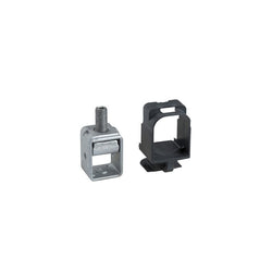
TeSys GV7 - clip-on connector - up to 150 A - 1.5...95 mm2
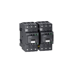
TeSys D reversing contactor - 3P - <= 440 V - 65 A AC-3 - 100...250 V AC/DC coil


Reflex iC60N Ti24 16 A 2P curve C integrated control MCB
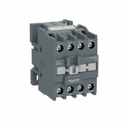
EasyPact TVS contactor 3P(3 NO) - AC-3 - = 440 V 38A - 48 V AC coil

Acti9 iC60 RCBO - 2P - 20 A - C Curve - 10000A/15kA - 30 mA - AC type
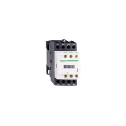
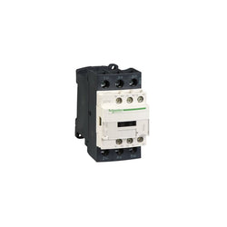
TeSys D contactor - 4P(4 NO) - AC-1 - <= 440 V 20 A - 230 V AC 50/60 Hz coil

Main
| Characteristic | Value(s) |
|---|---|
| Range | TeSys |
| product name | TeSys F |
| Product or Component Type | Contactor |
| Device short name | LC1F |
| Contactor application | Resistive load |
| Utilisation category | AC-1 |
| Poles description | 3P |
| power pole contact composition | 3 NO |
| [Ue] rated operational voltage | <= 1000 V AC 50/60 Hz |
| [Ie] rated operational current | 2600 A 140 °F (60 °C)) <= 440 V AC AC-1 |
Complementary
| Characteristic | Value(s) |
|---|---|
| [Uc] control circuit voltage | 110...500 V AC 40...400 Hz with LX1/LX9 coil 110...440 V DC with LX4 coil |
| [Uimp] rated impulse withstand voltage | 8 kV |
| Overvoltage category | III |
| [Ith] conventional free air thermal current | 2600 A (at 140 °F (60 °C)) |
| Irms rated making capacity | 3900 A AC conforming to IEC 60947-4-1 |
| Rated breaking capacity | 3900 A conforming to IEC 60947-4-1 |
| [Icw] rated short-time withstand current | 12000 A 104 °F (40 °C) - 10 s 9000 A 104 °F (40 °C) - 30 s 7000 A 104 °F (40 °C) - 1 min 6000 A 104 °F (40 °C) - 3 min 4000 A 104 °F (40 °C) - 10 min |
| Associated fuse rating | 2500 A gG at <= 440 V |
| Average impedance | 0.1 mOhm - Ith 2600 A 50 Hz |
| [Ui] rated insulation voltage | 1000 V IEC 60947-4-1 |
| Power dissipation per pole | 250 W AC-1 |
| Control circuit voltage limits | Operational: 0.85...1.1 Uc AC 40...400 Hz with LX1/LX9 coil Drop-out: 0.3...0.5 Uc AC 40...400 Hz with LX1/LX9 coil Operational: 0.85...1.1 Uc DC with LX4 coil Drop-out: 0.2...0.35 Uc DC with LX4 coil |
| Heat dissipation | 25 W |
| Operating time | 40...80 ms closing with LX1/LX9 coil 100...200 ms opening with LX1/LX9 coil 60...70 ms closing with LX4 coil 40...50 ms opening with LX4 coil |
| Mounting Support | Plate |
| Standards | IEC 60947-1 IEC 60947-4-1 EN 60947-4-1 JIS C8201-4-1 EN 60947-1 |
| Product Certifications | cETLus CCC CSA CB UKCA |
| Connections - terminals | Power circuit bar 3 100 x 10 mm Control circuit screw clamp terminals 1 0.002â¦0.006 in² (1â¦4 mm²)flexible without cable end Control circuit screw clamp terminals 2 0.002â¦0.006 in² (1â¦4 mm²)flexible with cable end Control circuit screw clamp terminals 1 0.002â¦0.006 in² (1â¦4 mm²)flexible with cable end Control circuit screw clamp terminals 2 0.002â¦0.004 in² (1â¦2.5 mm²)solid without cable end Control circuit screw clamp terminals 1 0.002â¦0.006 in² (1â¦4 mm²) Control circuit screw clamp terminals 2 0.002â¦0.006 in² (1â¦4 mm²) |
| Tightening torque | Power circuit 513.3 lbf.in (58 N.m) Control circuit 10.6 lbf.in (1.2 N.m) |
| Mechanical durability | 0.5 Mcycles |
| Inrush power in VA | 2200â¦2700 VA, 40...400 Hz cos phi 0.9 (at 68 °F (20 °C))with LX1/LX9 coil 2130â¦2880 VA (at 68 °F (20 °C))with LX4 coil |
| Hold-in power consumption in VA | 37.4â¦50.6 VA, 40...400 Hz cos phi 0.9 (at 68 °F (20 °C))with LX1/LX9 coil 13â¦25 VA (at 68 °F (20 °C))with LX4 coil |
| Maximum operating rate | 600 cyc/h 131 °F (55 °C) |
| Compatibility code | LC1F |

PLC Direct is not an authorized distributor. We offer a broad range of in-stock products with minimal lead time.

Motor circuit breaker, TeSys GV2, 3P, 1 A, magnetic, toggle control, screw clamp terminals
TeSys D contactor 3P 9A AC-3 up to 440V coil 100-250V AC/DC