
 1 year warranty

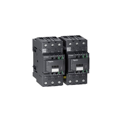
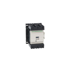
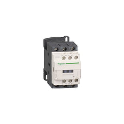
TeSys Deca reversing contactor, 3 poles (3NO), for motor control applications up to 50A/590V AC-3 (22kW@400V). Rated 50A AC-3 22kW@400V, it includes a 24V DC low consumption electronic coil for direct PLC control, 2NO+2NC aux contacts, mechanical interlock. It provides low consumption 24V DC coils with electronic control, 2NO+2NC built-in auxiliary contacts (NC mirror contacts), power connection by EverLink BTR screw connectors, control by screw clamp terminals. For operating rates until 3600 cycles/hour and environments until 60°C, it procures high reliability and durability. Compact (119mm width), DIN-rail mounting or screw fixing. With pre-wired reversing power connections, mechanical interlock (without electrical interlocking). Multi standards certified (IEC, UL, CSA, CCC, EAC, Marine). Assembled with mechanical interlock and pre-wired reversing circuit. Clear separation between power and control circuits, easy front access to coil and auxiliary contacts connections. Equipped with an electronic 24V DC coil, low consumption, for a direct control by a PLC output 24V DC / 500mA. Provides 4 built-in auxiliary contacts 2NO + 2NC, NC contacts are mirror certified suitable to be included in the control of safety systems. High electrical durability, guaranteed for 1.6 million cycles at 50A AC-3 440V, for demanding motor switching applications. Robust design with high making and breaking capacities up to 20 In. Power connections by EverLink BTR screw terminals providing constant tightening pressure.
Main
| Characteristic | Value(s) |
|---|---|
| Range | TeSys TeSys Deca |
| product name | TeSys Deca Tesys Deca green |
| Product or Component Type | Reversing contactor |
| Device short name | LC2D |
| Contactor application | Resistive load Motor control |
| Utilisation category | AC-1 AC-3 |
| Device presentation | Preassembled with reversing power busbar |
| Poles description | 3P |
| power pole contact composition | 3 NO |
| [Ue] rated operational voltage | Power circuit 690 V AC 25...400 Hz |
| [Ie] rated operational current | 50 A (at <140 °F (60 °C)) at <= 440 V AC-3 for power circuit 80 A (at <140 °F (60 °C)) at <= 440 V AC-1 for power circuit |
| Motor power kW | 15 kW at 220...230 V AC 50 Hz 22 kW at 380...400 V AC 50 Hz 25 kW at 415 V AC 50 Hz 30 kW at 440 V AC 50 Hz 30 kW at 500 V AC 50 Hz 33 kW at 660...690 V AC 50 Hz |
| motor power HP (UL / CSA) | 3 hp at 115 V AC 60 Hz for 1 phase motors 7.5 hp at 230/240 V AC 60 Hz for 1 phase motors 15 hp at 200/208 V AC 60 Hz for 3 phase motors 15 hp at 230/240 V AC 60 Hz for 3 phase motors 40 hp at 460/480 V AC 60 Hz for 3 phase motors 40 hp at 575/600 V AC 60 Hz for 3 phase motors |
| Control circuit type | DC DC low consumption |
| [Uc] control circuit voltage | 24 V DC |
| Auxiliary contact composition | 1 NO + 1 NC |
| [Uimp] rated impulse withstand voltage | 6 kV IEC 60947 |
| Overvoltage category | III |
| [Ith] conventional free air thermal current | 10 A (at 140 °F (60 °C)) for signalling circuit 80 A (at 140 °F (60 °C)) for power circuit |
| Irms rated making capacity | 140 A AC for signalling circuit conforming to IEC 60947-5-1 250 A DC for signalling circuit conforming to IEC 60947-5-1 900 A at 440 V for power circuit conforming to IEC 60947 |
| Rated breaking capacity | 900 A at 440 V for power circuit conforming to IEC 60947 |
| [Icw] rated short-time withstand current | 100 A - 1 s for signalling circuit 120 A - 500 ms for signalling circuit 140 A - 100 ms for signalling circuit 400 A 104 °F (40 °C) - 10 s for power circuit 810 A 104 °F (40 °C) - 1 s for power circuit 84 A 104 °F (40 °C) - 10 min for power circuit 208 A 104 °F (40 °C) - 1 min for power circuit |
| Associated fuse rating | 10 A gG for signalling circuit conforming to IEC 60947-5-1 100 A gG at <= 690 V coordination type 1 for power circuit 100 A gG at <= 690 V coordination type 2 for power circuit |
| Average impedance | 1.5 mOhm - Ith 80 A 50 Hz for power circuit |
| [Ui] rated insulation voltage | Power circuit 690 V IEC 60947-4-1 Signalling circuit 690 V IEC 60947-1 |
| Electrical durability | 1.8 Mcycles 42 A AC-3 <= 440 V 0.5 Mcycles 80 A AC-1 <= 440 V |
| Power dissipation per pole | 3.7 W AC-3 9.6 W AC-1 |
| Front cover | With |
| Interlocking type | Mechanical |
| Mounting Support | Rail Plate |
| Standards | EN/IEC 60947-4-1 EN/IEC 60947-5-1 UL 60947-4-1 CSA C22.2 No 60947-4-1 IEC 60335-1 |
| Product certifications | CCC CSA EAC UL KC DNV-GL LROS (Lloyds register of shipping) UKCA |
| Connections - terminals | Control circuit screw clamp terminals 1 0.002â¦0.006 in² (1â¦4 mm²)flexible without cable end Control circuit screw clamp terminals 2 0.002â¦0.006 in² (1â¦4 mm²)flexible without cable end Control circuit screw clamp terminals 1 0.002â¦0.006 in² (1â¦4 mm²)flexible with cable end Control circuit screw clamp terminals 2 0.002â¦0.004 in² (1â¦2.5 mm²)flexible with cable end Control circuit screw clamp terminals 1 0.002â¦0.006 in² (1â¦4 mm²)solid Control circuit screw clamp terminals 2 0.002â¦0.006 in² (1â¦4 mm²)solid Power circuit EverLink BTR screw connectors 1 0.002â¦0.05 in² (1â¦35 mm²)flexible without cable end Power circuit EverLink BTR screw connectors 2 0.002â¦0.04 in² (1â¦25 mm²)flexible without cable end Power circuit EverLink BTR screw connectors 1 0.002â¦0.05 in² (1â¦35 mm²)flexible with cable end Power circuit EverLink BTR screw connectors 2 0.002â¦0.04 in² (1â¦25 mm²)flexible with cable end Power circuit EverLink BTR screw connectors 1 0.002â¦0.05 in² (1â¦35 mm²)solid Power circuit EverLink BTR screw connectors 2 0.002â¦0.04 in² (1â¦25 mm²)solid |
| Tightening torque | Control circuit 15.05 lbf.in (1.7 N.m) screw clamp terminals flat à 6 mm Control circuit 15.05 lbf.in (1.7 N.m) screw clamp terminals Philips No 2 Power circuit 70.8 lbf.in (8 N.m) EverLink BTR screw connectors 0.04â¦0.05 in² (25â¦35 mm²) hexagonal 0.2 in (4 mm) Power circuit 44.3 lbf.in (5 N.m) EverLink BTR screw connectors 0.002â¦0.04 in² (1â¦25 mm²) hexagonal 0.2 in (4 mm) |
| Operating time | 55...65 ms closing 20...120 ms opening >= 17221) 20...80 ms opening >= 18011) |
| Safety reliability level | B10d = 1369863 cycles contactor with nominal load EN/ISO 13849-1 B10d = 20000000 cycles contactor with mechanical load EN/ISO 13849-1 |
| Mechanical durability | 6 Mcycles |
| Maximum operating rate | 3600 cyc/h 140 °F (60 °C) |
Complementary
| Characteristic | Value(s) |
|---|---|
| Coil technology | Built-in bidirectional peak limiting |
| Control circuit voltage limits | <= 0.1 Uc (-40â¦158 °F (-40â¦70 °C)):drop-out DC 0.8...1.2 Uc (-40â¦140 °F (-40â¦60 °C)):operational DC 1...1.2 Uc (140â¦158 °F (60â¦70 °C)):operational DC |
| Inrush power in W | 11 W 68 °F (20 °C) |
| Hold-in power consumption in W | 0.5 W 68 °F (20 °C) |
| Heat dissipation | 0.5 W |
| Auxiliary contacts type | Mechanically linked 1 NO + 1 NC IEC 60947-5-1 Mirror contact 1 NC IEC 60947-4-1 |
| Signalling circuit frequency | 25...400 Hz |
| Minimum switching current | 5 mA for signalling circuit |
| Minimum switching voltage | 17 V for signalling circuit |
| Non-overlap time | 1.5 ms on de-energisation between NC and NO contact 1.5 ms on energisation between NC and NO contact |
| Insulation resistance | > 10 MOhm for signalling circuit |
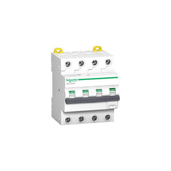
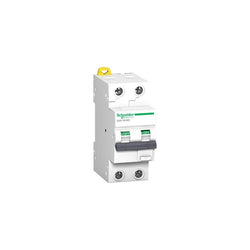
Acti9 iC60 RCBO - 4P - 16 A - C Curve - 6000A/6kA - 30 mA - AC type

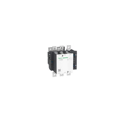
TeSys F contactor, 3 poles (3NO), 265A/1000V AC-3, for motor applications up to 132kW@400V. It provides a low sealed consumption 110V 40-400Hz AC coil, bolt terminals for bars or cables with lugs. For high operating rates until 2400 cycles/hour and environments until 55°C, it procures high reliability and durability. It makes installation and maintenance easy thanks to its drawer-mounted coil and a large choice of add-on blocks and accessories (to be ordered separately). Multi standards certified (IEC, UL, CSA, CCC, EAC, Marine), Green Premium compliant (RoHS/REACh).
Main
| Characteristic | Value(s) |
|---|---|
| Range | TeSys |
| Range of Product | TeSys F |
| Product or Component Type | Contactor |
| Device short name | LC1F |
| Contactor application | Resistive load Motor control |
| Utilisation category | AC-1 AC-4 AC-3 |
| Poles description | 3P |
| [Ue] rated operational voltage | <= 1000 V AC-1 <= 690 V AC-3 <= 690 V AC-4 <= 460 V DC |
| [Uc] control circuit voltage | 110 V AC 40...400 Hz |
| [Ie] rated operational current | 350 A (at <104 °F (40 °C)) at <= 440 V AC AC-1 265 A (at <131 °F (55 °C)) at <= 440 V AC AC-3 |
Complementary
| Characteristic | Value(s) |
|---|---|
| [Uimp] rated impulse withstand voltage | 8 kV |
| [Ith] conventional free air thermal current | 350 A (at 104 °F (40 °C)) |
| Rated breaking capacity | 2120 A conforming to IEC 60947-4-1 |
| [Icw] rated short-time withstand current | 2200 A 104 °F (40 °C) - 10 s 1230 A 104 °F (40 °C) - 30 s 950 A 104 °F (40 °C) - 1 min 620 A 104 °F (40 °C) - 3 min 480 A 104 °F (40 °C) - 10 min |
| Associated fuse rating | 315 A aM at <= 440 V 400 A gG at <= 440 V |
| Average impedance | 0.3 mOhm - Ith 350 A 50 Hz |
| [Ui] rated insulation voltage | 1000 V IEC 60947-4-1 1500 V VDE 0110 group C |
| Power dissipation per pole | 37 W AC-1 21 W AC-3 |
| Overvoltage category | III |
| power pole contact composition | 3 NO |
| Motor power kW | 132 kW at 380...400 V AC 50/60 Hz (AC-3) 140 kW at 415 V AC 50/60 Hz (AC-3) 140 kW at 440 V AC 50/60 Hz (AC-3) 160 kW at 500 V AC 50/60 Hz (AC-3) 160 kW at 660...690 V AC 50/60 Hz (AC-3) 147 kW at 1000 V AC 50/60 Hz (AC-3) 75 kW at 220...230 V AC 50/60 Hz (AC-3) 51 kW at 400 V AC 50/60 Hz (AC-4) |
| Control circuit voltage limits | Operational 0.85...1.1 Uc 40...400 Hz 131 °F (55 °C)) Drop-out 0.15...0.2 Uc 40...400 Hz 131 °F (55 °C)) |
| Mechanical durability | 10 Mcycles |
| Inrush power in VA | 650 VA, 40...400 Hz 0.9 68 °F (20 °C)) |
| Hold-in power consumption in VA | 10 VA, 40...400 Hz 0.9 68 °F (20 °C)) |
| Maximum operating rate | 2400 cyc/h 131 °F (55 °C) |
| Operating time | 40...65 ms closing 100...170 ms opening |
| Connections - terminals | Control circuit screw clamp terminals 1 0.002â¦0.006 in² (1â¦4 mm²)flexible without cable end Control circuit screw clamp terminals 2 0.002â¦0.006 in² (1â¦4 mm²)flexible without cable end Control circuit screw clamp terminals 1 0.002â¦0.006 in² (1â¦4 mm²)flexible with cable end Control circuit screw clamp terminals 2 0.002â¦0.004 in² (1â¦2.5 mm²)flexible with cable end Control circuit screw clamp terminals 1 0.002â¦0.006 in² (1â¦4 mm²)solid without cable end Control circuit screw clamp terminals 2 0.002â¦0.006 in² (1â¦4 mm²)solid without cable end Power circuit bar 2 32 x 4 mm Power circuit lugs-ring terminals 1 0.4 in² (240 mm²) Power circuit connector 1 0.4 in² (240 mm²) Power circuit bolted connection |
| Tightening torque | Control circuit 10.6 lbf.in (1.2 N.m) Power circuit 309.8 lbf.in (35 N.m) |
| Mounting Support | Plate |
| Heat dissipation | 8 W |
| motor power range | 55â¦100 kW 200â¦240 V 3 phase 110â¦220 kW 480â¦500 V 3 phase 110â¦220 kW 380â¦440 V 3 phase |
| Motor starter type | Direct on-line contactor |
| Contactor coil voltage | 110 V AC standard |
| Standards | EN 60947-4-1 JIS C8201-4-1 EN 60947-1 IEC 60947-1 IEC 60947-4-1 |
| Product Certifications | BV RINA CSA UL DNV RMRoS CB LROS (Lloyds register of shipping) ABS UKCA |
| Compatibility code | LC1F |
| Control circuit type | AC 40...400 Hz |


PLC Direct is not an authorized distributor. We offer a broad range of in-stock products with minimal lead time.
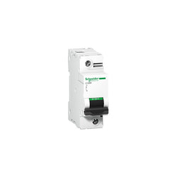
This Acti9 C120N is a low voltage multistandard miniature circuit breaker (MCB). It is a 1P circuit breaker with 1 protected pole, 125A rated current and B tripping curve. The rated short circuit breaking capacity goes up to 3kA at 380VAC to 415VAC conforming to EN/IEC 60947-2 standard and 3kA at 380VAC to 415VAC conforming to EN/IEC 60947-2 standard. It complies with both industrial standard EN/IEC 60898-1 and residential standard EN/IEC 60947-2. This miniature circuit breaker protects circuit against short circuit and overload current. The presence of green strip guarantees contact open physically and allows work to be carried out safely on the downstream circuit. It has good overvoltage withstand capacity. The product is designed to offer a high industrial performance level It has an electrical endurance going up to 5000 cycles and a mechanical endurance going up to 20000 cycles. The Ue operational voltage is going from 380VAC to 415VAC. The Ui rated insulation voltage is 500VAC. Its limitation class 3 (according to EN/IEC60898-1) improves downstream circuit protection cost. The product can be clipped on a DIN rail. Its width is 3 pitches of 9mm. Pollution degree is 3. Overvoltage category is IV. The product colour is white (RAL9003). The dimensions are (W) 27mm x (H) 81mm x (D) 73mm. The weight is 0.205kg. It has an IP20 degree of protection (as per IEC/EN 60529) on its terminals. The operating temperature is -25°C to 70°C. The storage temperature is -40°C to 85°C.
Main
| Characteristic | Value(s) |
|---|---|
| Range | Acti9 |
| product name | Acti9 C120 |
| Product or component type | Miniature circuit-breaker |
| Device short name | C120N |
| Device application | Distribution |
| Poles description | 1P |
| Number of protected poles | 1 |
| [In] rated current | 125 A at 30 °C |
| Network type | AC |
| Trip unit technology | Thermal-magnetic |
| Curve code | B |
| Breaking capacity | 3 kA Icu at 380...415 V AC 50/60 Hz IT conforming to EN/IEC 60947-2 20 kA Icu at 130 V AC 50/60 Hz conforming to EN/IEC 60947-2 15 kA Icu at 12 V DC conforming to EN/IEC 60947-2 15 kA Icu at 125 V DC conforming to EN/IEC 60947-2 10 kA Icu at <= 144 V DC conforming to EN/IEC 60947-2 10 kA Icu at 220...240 V AC 50/60 Hz conforming to EN/IEC 60947-2 20 kA Icu at 12 V AC 50/60 Hz conforming to EN/IEC 60947-2 10000 A Icn at 230...400 V AC 50/60 Hz conforming to EN/IEC 60898-1 |
| Suitability for isolation | Yes conforming to IEC 60947-2 |
| Standards | EN/IEC 60947-2 EN/IEC 60898-1 |
| Product certifications | EAC |
Complementary
| Characteristic | Value(s) |
|---|---|
| Network frequency | 50/60 Hz |
| [Ue] rated operational voltage | 380...415 V AC 50/60 Hz 125 V DC <= 144 V DC 12 V DC 220...240 V AC 50/60 Hz 230...400 V AC 50/60 Hz 130 V AC 50/60 Hz 12 V AC 50/60 Hz |
| Magnetic tripping limit | 3...5 x In |
| [Ics] rated service breaking capacity | 15 kA 75 % conforming to EN/IEC 60947-2 - 130 V AC 50/60 Hz 15 kA 100 % conforming to EN/IEC 60947-2 - 125 V DC 2.25 kA 75 % conforming to EN/IEC 60947-2 - 380...415 V AC 50/60 Hz 15 kA 100 % conforming to EN/IEC 60947-2 - 12 V DC 10 kA 100 % conforming to EN/IEC 60947-2 - <= 144 V DC 7.5 kA 75 % conforming to EN/IEC 60947-2 - 220...240 V AC 50/60 Hz 15 kA 75 % conforming to EN/IEC 60947-2 - 12 V AC 50/60 Hz 7500 A 75 % conforming to EN/IEC 60898-1 - 230...400 V AC 50/60 Hz |
| Limitation class | 3 conforming to EN/IEC 60947-2 |
| [Ui] rated insulation voltage | 500 V AC 50/60 Hz conforming to EN/IEC 60947-2 |
| [Uimp] rated impulse withstand voltage | 6 kV conforming to EN/IEC 60947-2 |
| Contact position indicator | Yes |
| control type | Toggle |
| Local signalling | ON/OFF indication |
| Mounting mode | Clip-on |
| Mounting support | 35 mm symmetrical DIN rail |
| Comb busbar and distribution block compatibility | YES |
| 9 mm pitches | 3 |
| Height | 81 mm |
| Depth | 73 mm |
| Width | 27 mm |
| Product weight | 0.205 kg |
| Colour | White |
| Mechanical durability | 20000 cycles |
| Electrical durability | 5000 cycles conforming to IEC 60947-2 |
| Locking options description | Handle sealable with cable diameter 0.7mm in OFF or ON position |
| Connections - terminals | Tunnel type terminals1â¦50 mm² rigid Tunnel type terminals1.5â¦35 mm² flexible |
| Wire stripping length | 15 mm |
| Tightening torque | 3.5 N.m |
| Earth-leakage protection | Without |

C60PV-DC - 2P - 16A - 800 V - B curve

TeSys D contactor - 3P(3 NO) - AC-3 - <= 440 V 150 A - 115 V AC 50/60 Hz coil

PLC Direct is not an authorized distributor. We offer a broad range of in-stock products with minimal lead time.
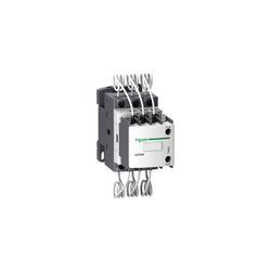
Capacitor contactor, TeSys D, 16.7 kVAR at 400 V/50 Hz, coil 415 V AC 50/60 Hz
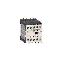
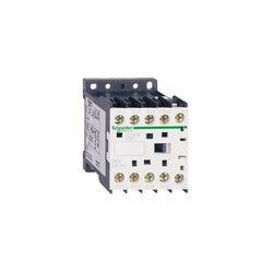
TeSys K contactor, 3 poles (3NO), for motor control applications up to 12A/690V AC-3 (5.5kW@400V), and for non-inductive load control applications up to 20A/690V AC-1. It provides a 220V 50/60Hz AC coil, 1NO built-in auxiliary contact, connection by solder pins for printed circuit boards. For operating rates until 600 cycles/hour and environments until 50°C, it procures reliability and durability to standard applications. Very compact (45mm width), DIN-rail mounting or screw fixing. Multi standards certified (IEC, UL, CSA, CCC, EAC), Green Premium compliant (RoHS/REACh).
Main
| Characteristic | Value(s) |
|---|---|
| Range | TeSys |
| Product or Component Type | Contactor |
| Device short name | LC1K |
| Device Application | Control |
| Contactor application | Resistive load Motor control |
Complementary
| Characteristic | Value(s) |
|---|---|
| Utilisation category | AC-3 AC-3e AC-1 AC-4 |
| Poles description | 3P |
| power pole contact composition | 3 NO |
| [Ue] rated operational voltage | Power circuit <= 690 V AC <= 400 Hz Signalling circuit <= 690 V AC <= 400 Hz |
| [Ie] rated operational current | 12 A (at <140 °F (60 °C)) at <= 440 V AC AC-3 for power circuit 12 A (at <140 °F (60 °C)) at <= 440 V AC AC-3e for power circuit 20 A (at <140 °F (60 °C)) at <= 690 V AC AC-1 for power circuit |
| Control circuit type | AC 50/60 Hz |
| [Uc] control circuit voltage | 220...230 V AC 50/60 Hz |
| Motor power kW | 3 kW 220...230 V AC 50/60 Hz AC-3 5.5 kW 380...415 V AC 50/60 Hz AC-3 5.5 kW 440 V AC 50/60 Hz AC-3 4 kW 690 V AC 50/60 Hz AC-3 3 kW 220...230 V AC 50/60 Hz AC-3e 5.5 kW 380...415 V AC 50/60 Hz AC-3e 5.5 kW 440 V AC 50/60 Hz AC-3e 4 kW 690 V AC 50/60 Hz AC-3e 3 kW 220...230 V AC 50/60 Hz AC-4 5.5 kW 380...415 V AC 50/60 Hz AC-4 5.5 kW 440 V AC 50/60 Hz AC-4 4 kW 690 V AC 50/60 Hz AC-4 |
| Auxiliary contact composition | 1 NO |
| [Uimp] rated impulse withstand voltage | 8 kV |
| Overvoltage category | III |
| [Ith] conventional free air thermal current | 20 A (at 140 °F (60 °C)) for power circuit 10 A (at 122 °F (50 °C)) for signalling circuit |
| Irms rated making capacity | 144 A AC for power circuit conforming to IEC 60947 110 A AC for signalling circuit conforming to IEC 60947 |
| Rated breaking capacity | 110 A at 440 V conforming to IEC 60947 80 A at 500 V conforming to IEC 60947 70 A at 660...690 V conforming to IEC 60947 |
| [Icw] rated short-time withstand current | 115 A 122 °F (50 °C) - 1 s for power circuit 105 A 122 °F (50 °C) - 5 s for power circuit 100 A 122 °F (50 °C) - 10 s for power circuit 75 A 122 °F (50 °C) - 30 s for power circuit 55 A 122 °F (50 °C) - 1 min for power circuit 50 A 122 °F (50 °C) - 3 min for power circuit 25 A 122 °F (50 °C) - >= 15 min for power circuit 80 A - 1 s for signalling circuit 90 A - 500 ms for signalling circuit 110 A - 100 ms for signalling circuit |
| Associated fuse rating | 25 A gG at <= 440 V for power circuit 25 A aM for power circuit 10 A gG for signalling circuit conforming to IEC 60947 10 A gG for signalling circuit conforming to VDE 0660 |
| Average impedance | 3 mOhm - Ith 20 A 50 Hz for power circuit |
| [Ui] rated insulation voltage | Power circuit 600 V UL 508 Power circuit 690 V IEC 60947-4-1 Signalling circuit 690 V IEC 60947-4-1 Signalling circuit 690 V IEC 60947-5-1 Signalling circuit 600 V UL 508 Power circuit 600 V CSA C22.2 No 14 Signalling circuit 600 V CSA C22.2 No 14 |
| Insulation resistance | > 10 MOhm for signalling circuit |
| Inrush power in VA | 30 VA (at 68 °F (20 °C)) |
| Hold-in power consumption in VA | 4.5 VA (at 68 °F (20 °C)) |
| Heat dissipation | 1.3 W |
| Control circuit voltage limits | Operational: 0.8...1.15 Uc (at <122 °F (50 °C)) Drop-out: >= 0.20 Uc (at <122 °F (50 °C)) |
| Connections - terminals | solder pins 0.001 in (0.035 mm)) |
| Maximum operating rate | 3600 cyc/h |
| Auxiliary contacts type | Instantaneous 1 NO |
| Signalling circuit frequency | <= 400 Hz |
| Minimum switching current | 5 mA for signalling circuit |
| Minimum switching voltage | 17 V for signalling circuit |
| Mounting Support | Printed circuit boards |
| Operating time | 10...20 ms coil de-energisation and NO opening 10...20 ms coil energisation and NO closing |
| Safety reliability level | B10d = 1369863 cycles contactor with nominal load EN/ISO 13849-1 B10d = 20000000 cycles contactor with mechanical load EN/ISO 13849-1 |
| Non overlap distance | 0.02 in (0.5 mm) |
| Mechanical durability | 10 Mcycles |
| Electrical durability | 1.3 Mcycles 12 A AC-3 <= 440 V 1.3 Mcycles 12 A AC-3e <= 440 V 0.3 Mcycles 20 A AC-1 <= 690 V 0.02 Mcycles 72 A AC-4 <= 440 V |
| Mechanical robustness | Shocks contactor closed, on X axis10 Gn for 11 ms IEC 60068-2-27 Shocks contactor closed, on Y axis15 Gn for 11 ms IEC 60068-2-27 Shocks contactor closed, on Z axis15 Gn for 11 ms IEC 60068-2-27 Shocks contactor opened, on X axis6 Gn for 11 ms IEC 60068-2-27 Shocks contactor opened, on Y axis10 Gn for 11 ms IEC 60068-2-27 Shocks contactor opened, on Z axis10 Gn for 11 ms IEC 60068-2-27 Vibrations contactor closed4 Gn, 5...300 Hz IEC 60068-2-6 Vibrations contactor opened2 Gn, 5...300 Hz IEC 60068-2-6 |
| Height | 2.3 in (58 mm) |
| Width | 1.8 in (45 mm) |
| Depth | 2.2 in (57 mm) |
| Product Weight | 0.40 lb(US) (0.18 kg) |
TeSys D contactor - 3P(3 NO) - AC-3 - <= 440 V 12 A - 110 V AC coil

This Acti9 iID is a modular and reliable residual current circuit breaker (RCCB). It is a 2P circuit breaker with In rated current of 80A, AC type protection class and a 30mA earth leakage sensitivity. This product protects against electrical shock by direct or indirect contact and fire hazards. It performs the function of disconnection of electrical circuits in case of earth fault. Its unique Visitrip indicator reduces intervention time by showing the faulty device with a mechanical indicator on front face. This product also has a VisiSafe window with a green strip on the toggle indicating full opening of the poles allowing downstream maintenance This product is compliant with EN/IEC 61008-1 standard. The (Im/IÎm) rated breaking and making short circuit capacity is 1500A. The (Inc/IÎc) conditional rated short circuit current is 10kA. The electrical endurance is up to 10000 cycles. The mechanical endurance is up to 20000 cycles. The Ue operational voltage is 220VAC to 240VAC. The Ui rated insulation voltage is 500VAC. The Uimp rated impulse withstand voltage is 6kV. The frequency is 50Hz or 60Hz. It is DIN rail mountable. The width in 9mm pitches is 4. The product colour is white (RAL9003). The dimensions are (W) 36mm x (H) 91mm x (D) 73.5mm. The weight is 0.21kg. It has an IP20 degree of protection. It becomes IP40 once in modular enclosure according to IEC/EN 60529 standard. The operating temperature is from -5°C to 60°C. The storage temperature is from -40°C to 85°C.
Main
| Characteristic | Value(s) |
|---|---|
| Range | Acti9 |
| product name | Acti9 iID |
| Product or component type | Residual current circuit breaker (RCCB) |
| Device short name | iID |
| Poles description | 2P |
| Neutral position | Left |
| [In] rated current | 80 A |
| Network type | AC |
| Earth-leakage sensitivity | 30 mA |
| Earth-leakage protection time delay | Instantaneous |
| Earth-leakage protection class | Type AC |
Complementary
| Characteristic | Value(s) |
|---|---|
| Device location in system | Outgoer |
| Network frequency | 50/60 Hz |
| [Ue] rated operational voltage | 220...240 V AC 50/60 Hz |
| Residual current tripping technology | Voltage independent |
| Rated breaking and making capacity | Idm 1500 A Im 1500 A |
| Rated conditional short-circuit current | 10 kA |
| [Ui] rated insulation voltage | 500 V AC 50/60 Hz |
| [Uimp] rated impulse withstand voltage | 6 kV |
| Contact position indicator | Yes |
| control type | Toggle |
| Mounting mode | Clip-on |
| Mounting support | DIN rail |
| 9 mm pitches | 4 |
| Height | 91 mm |
| Width | 36 mm |
| Depth | 73.5 mm |
| Product weight | 0.21 kg |
| Colour | White |
| Mechanical durability | 20000 cycles |
| Electrical durability | AC-1: 10000 cycles |
| Locking options description | Padlocking device |
| Connections - terminals | Single terminal top or bottom 1â¦35 mm² rigid Single terminal top or bottom 1â¦25 mm² flexible Single terminal top or bottom 1â¦25 mm² flexible with ferrule |
| Wire stripping length | 14 mm for top or bottom connection |
| Tightening torque | 3.5 N.m top or bottom |
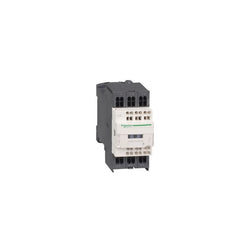
TeSys K contactor, 3 poles (3NO), for motor control applications up to 16A/690V AC-3 (7.5kW@400V). It provides a 220V 50/60Hz AC coil, 1NO built-in auxiliary contact, connection by screw clamp terminals. For operating rates until 600 cycles/hour and environments until 50°C, it procures reliability and durability to standard applications. Very compact (45mm width), DIN-rail mounting or screw fixing. Multi standards certified (IEC, UL, CSA, CCC, EAC).
Main
| Characteristic | Value(s) |
|---|---|
| Range | TeSys |
| Product or component type | Contactor |
| Device short name | LC1K |
| Device application | Control |
| Contactor application | Motor control |
Complementary
| Characteristic | Value(s) |
|---|---|
| Utilisation category | AC-3 AC-3e |
| Poles description | 3P |
| power pole contact composition | 3 NO |
| [Ue] rated operational voltage | Power circuit: <= 690 V AC <= 400 Hz Signalling circuit: <= 690 V AC <= 400 Hz |
| [Ie] rated operational current | 16 A (at <60 °C) at <= 440 V AC AC-3 for power circuit 16 A (at <60 °C) at <= 440 V AC AC-3e for power circuit |
| Control circuit type | AC at 50/60 Hz |
| [Uc] control circuit voltage | 220...230 V AC 50/60 Hz |
| Motor power kW | 4 kW at 220...230 V AC 50/60 Hz AC-3 7.5 kW at 380...415 V AC 50/60 Hz AC-3 5.5 kW at 440 V AC 50/60 Hz AC-3 4 kW at 690 V AC 50/60 Hz AC-3 4 kW at 220...230 V AC 50/60 Hz AC-3e 7.5 kW at 380...415 V AC 50/60 Hz AC-3e 5.5 kW at 440 V AC 50/60 Hz AC-3e 4 kW at 690 V AC 50/60 Hz AC-3e |
| Auxiliary contact composition | 1 NO |
| [Uimp] rated impulse withstand voltage | 8 kV |
| Overvoltage category | III |
| [Ith] conventional free air thermal current | 20 A (at 60 °C) for power circuit 10 A (at 50 °C) for signalling circuit |
| Irms rated making capacity | 160 A AC for power circuit conforming to IEC 60947 110 A AC for signalling circuit conforming to IEC 60947 |
| Rated breaking capacity | 110 A at 440 V conforming to IEC 60947 80 A at 500 V conforming to IEC 60947 70 A at 660...690 V conforming to IEC 60947 |
| [Icw] rated short-time withstand current | 115 A 50 °C - 1 s for power circuit 105 A 50 °C - 5 s for power circuit 100 A 50 °C - 10 s for power circuit 75 A 50 °C - 30 s for power circuit 55 A 50 °C - 1 min for power circuit 50 A 50 °C - 3 min for power circuit 25 A 50 °C - >= 15 min for power circuit 80 A - 1 s for signalling circuit 90 A - 500 ms for signalling circuit 110 A - 100 ms for signalling circuit |
| Associated fuse rating | 25 A gG at <= 440 V for power circuit 25 A aM for power circuit 10 A gG for signalling circuit conforming to IEC 60947 10 A gG for signalling circuit conforming to VDE 0660 |
| Average impedance | 3 mOhm - Ith 20 A 50 Hz for power circuit |
| [Ui] rated insulation voltage | Power circuit: 600 V conforming to UL 508 Power circuit: 690 V conforming to IEC 60947-4-1 Signalling circuit: 690 V conforming to IEC 60947-4-1 Signalling circuit: 690 V conforming to IEC 60947-5-1 Signalling circuit: 600 V conforming to UL 508 Power circuit: 600 V conforming to CSA C22.2 No 14 Signalling circuit: 600 V conforming to CSA C22.2 No 14 |
| Insulation resistance | > 10 MOhm for signalling circuit |
| Inrush power in VA | 30 VA (at 20 °C) |
| Hold-in power consumption in VA | 4.5 VA (at 20 °C) |
| Heat dissipation | 1.3 W |
| Control circuit voltage limits | Operational: 0.8...1.15 Uc (at <50 °C) Drop-out: >= 0.20 Uc (at <50 °C) |
| Connections - terminals | Screw clamp terminals 1 cable(s) 1.5â¦4 mm²solid Screw clamp terminals 1 cable(s) 0.75â¦4 mm²flexible without cable end Screw clamp terminals 1 cable(s) 0.34â¦2.5 mm²flexible with cable end Screw clamp terminals 2 cable(s) 1.5â¦4 mm²solid Screw clamp terminals 2 cable(s) 0.75â¦4 mm²flexible without cable end Screw clamp terminals 2 cable(s) 0.34â¦1.5 mm²flexible with cable end |
| Maximum operating rate | 3600 cyc/h |
| Auxiliary contacts type | type instantaneous 1 NO |
| Signalling circuit frequency | <= 400 Hz |
| Minimum switching current | 5 mA for signalling circuit |
| Minimum switching voltage | 17 V for signalling circuit |
| Mounting support | Plate Rail |
| Tightening torque | 0.8â¦1.3 N.m - on screw clamp terminals Philips No 2 0.8â¦1.3 N.m - on screw clamp terminals flat à 6 mm 0.8â¦1.3 N.m - on screw clamp terminals pozidriv No 2 |
| Operating time | 10...20 ms coil de-energisation and NO opening 10...20 ms coil energisation and NO closing |
| Safety reliability level | B10d = 1369863 cycles contactor with nominal load conforming to EN/ISO 13849-1 B10d = 20000000 cycles contactor with mechanical load conforming to EN/ISO 13849-1 |
| Non overlap distance | 0.5 mm |
| Mechanical durability | 10 Mcycles |
| Electrical durability | 1.3 Mcycles 16 A AC-3 at Ue <= 440 V 1.3 Mcycles 16 A AC-3e at Ue <= 440 V |
| Mechanical robustness | Shocks contactor closed, on X axis: 10 Gn for 11 ms conforming to IEC 60068-2-27 Shocks contactor closed, on Y axis: 15 Gn for 11 ms conforming to IEC 60068-2-27 Shocks contactor closed, on Z axis: 15 Gn for 11 ms conforming to IEC 60068-2-27 Shocks contactor opened, on X axis: 6 Gn for 11 ms conforming to IEC 60068-2-27 Shocks contactor opened, on Y axis: 10 Gn for 11 ms conforming to IEC 60068-2-27 Shocks contactor opened, on Z axis: 10 Gn for 11 ms conforming to IEC 60068-2-27 Vibrations contactor closed: 4 Gn, 5...300 Hz conforming to IEC 60068-2-6 Vibrations contactor opened: 2 Gn, 5...300 Hz conforming to IEC 60068-2-6 |
| Height | 58 mm |
| Width | 45 mm |
| Depth | 57 mm |
| Product weight | 0.18 kg |

Capacitor contactor, TeSys D, 25 kVAR at 400 V/50 Hz, coil 24 V AC 50/60 Hz
Acti9 iC60 RCBO - 2P - 25 A - C Curve - 10000A/15kA - 30 mA - AC type


Motor circuit breaker, TeSys GV6, 3P, 500A, Icu 36kA, thermal magnetic
TeSys D contactor - 3P(3 NO) - AC-3 - <= 440 V 18 A - 48 V AC coil
Motor circuit breaker, TeSys GV4, 3P, 25A, Icu 25kA, thermal magnetic, lugs terminals