
 1 year warranty


Input Module DIN Rail 100 ~ 240VAC, 24VDC

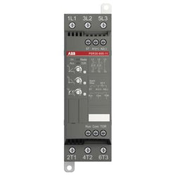
Servo AC 220VAC Supply 8.3A Load

AS200 CPU, NPN SINKING OUTPUT

AS200 CPU, RELAY OUTPUT
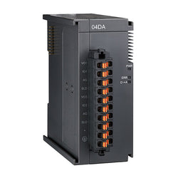
OUTPUT MODULE 4 ANALOG

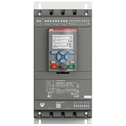
Soft starter, Altistart 480, 47A, 208 to 690V AC, control supply 110 to 230V AC
Ordering
Popular Downloads
Dimensions
Technical
Technical UL/CSA
Environmental
Material Compliance
Certificates and Declarations
Container Information
External Classifications and Standards
Ordering
Popular Downloads
Dimensions
Technical
Technical UL/CSA
Environmental
Material Compliance
Certificates and Declarations
Container Information
External Classifications and Standards
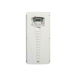
AC DRIVE ACS550 SERIES, IEC INSTALLATION AND COMPLIANCE, THREE-PHASE, 380-480 VAC, 50/60 HZ, 157 A, 75 KW, UL TYPE/NEMA 1
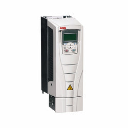
ACS550 IP21 45kW/55kW 400V 3ph AC Inverter Drive, HMI, C2 EMC
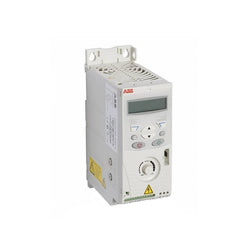
ACS150 1.5kW 400V 3ph AC Inverter Drive, DBr, C3 EMC
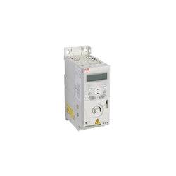
ACS150 0.37kW 400V 3ph AC Inverter Drive, DBr, C3 EMC

15 Touch Display

GP-4303T: 5.7" TFT COLOR TOUCH (ANALOG), QVGA, 2X SERIAL (1X MPI), ETHERNET, 2X USB, SD, 24VDC, UL/CE

OPERATOR INTERFACE, GP3000 SERIES, 7.5 INCH, TFT COLOR, LCD, 2 SERIAL, 1 USB, ETHERNET, 24 VDC

This XPSAK safety module monitors emergency shutdown pushbuttons, limit switches, light curtains and safety mats/edges. It meets the requirements of Performance Level PL e/Category 4 conforming to standard EN/ISO 13849-1 and SILCL3 conforming to EN/IEC 61508 and EN/IEC 62061. It can be used for monitoring emergency stop circuits conforming to standards EN/ISO 13850 and EN/IEC 60204-1. It can also be used for electrical monitoring of switches activated by protection devices, with optional selection of synchronisation time between signals, monitoring of 4-wire sensing mats or edges. And monitoring of type 4 light curtains conforming to EN/IEC 61496-1 which have solid-state safety outputs with test function (light curtains XUSL). It is compatible with emergency push buttons, limit switches, safety light curtains and safety mats/edges, the 4 most common safety sensors in the industry. It has additional solid-state output for communication with PLCs about safety status of your process.
Main
| Characteristic | Value(s) |
|---|---|
| Range of Product | Preventa Safety automation |
| Product or Component Type | Preventa safety module |
| Safety module name | XPSAK |
| Safety module application | For emergency stop, switch, sensing mat/edges or safety light curtain monitoring |
| Function of module | Multiple emergency stop monitoring 2-channel wiring Proximity sensor monitoring Monitoring of a movable guard Sensing mat and edges monitoring Emergency stop with 2 NC contacts monitoring 2-channel wiring Emergency stop monitoring 1-channel wiring Monitoring of a movable guard associated with 2 switches and automatic start Monitoring of electro-sensitive protection equipment (ESPE) |
| Safety level | Can reach PL e/category 4 EN/ISO 13849-1 Can reach SILCL 3 EN/IEC 62061 |
| Safety reliability data | DC > 99 % EN/ISO 13849-1 MTTFd = 154.5 years EN/ISO 13849-1 PFHd = 7.39E-9 1/h EN/IEC 62061 |
| Type of start | Configurable |
| Connections - terminals | Captive screw clamp terminals, 1 x 0.14...1 x 2.5 mm² flexible with cable end, with double bezel Captive screw clamp terminals, 1 x 0.14...1 x 2.5 mm² solid with cable end, with double bezel Captive screw clamp terminals, 1 x 0.25...1 x 1.5 mm² flexible with cable end, with double bezel Captive screw clamp terminals, 1 x 0.25...1 x 2.5 mm² flexible with cable end, with double bezel Captive screw clamp terminals, 2 x 0.14...2 x 0.75 mm² flexible with cable end, with double bezel Captive screw clamp terminals, 2 x 0.14...2 x 0.75 mm² solid with cable end, with double bezel Captive screw clamp terminals, 2 x 0.25...2 x 1 mm² flexible with cable end, with double bezel Captive screw clamp terminals, 2 x 0.5...2 x 1.5 mm² flexible with cable end, with double bezel |
| Output type | Relay instantaneous opening, 3 NO, volt-free |
| Number of additional circuits | 1 NC + 4 solid state outputs |
| [Us] Rated Supply Voltage | 230 V AC - 15...10 % 24 V DC - 15...10 % |
Complementary
| Characteristic | Value(s) |
|---|---|
| Synchronisation time between inputs | Unlimited (manual start) 2 or 4 s depending of wiring (automatic start) |
| Supply frequency | 50/60 Hz |
| Maximum power consumption in VA | 6 VA AC |
| Input protection type | Internal, electronic |
| [Uc] control circuit voltage | 24 V DC |
| Maximum line resistance | 28 Ohm |
| Breaking capacity | 180 VA holding AC-15 C300 relay output 1800 VA inrush AC-15 C300 relay output |
| Breaking capacity | 1.5 A 24 V DC-13)50 ms relay output |
| Output thermal current | 6 A per relay relay output |
| [Ith] conventional free air thermal current | 18 A |
| Associated fuse rating | 4 A gG or gL relay output EN/IEC 60947-5-1, DIN VDE 0660 part 200 6 A fast blow relay output EN/IEC 60947-5-1, DIN VDE 0660 part 200 |
| Minimum output current | 10 mA relay output |
| Minimum output voltage | 17 V relay output |
| Maximum response time on input open | 40 ms |
| [Ui] rated insulation voltage | 300 V 2)IEC 60947-5-1 300 V 2)DIN VDE 0110 part 1 |
| [Uimp] rated impulse withstand voltage | 4 kV III IEC 60947-5-1 4 kV III DIN VDE 0110 part 1 |
| Local signalling | 4 LEDs |
| Current consumption | 30 mA 24 V AC on power supply |
| Mounting Support | 35 mm symmetrical DIN rail |
| Product Weight | 0.9 lb(US) (0.4 kg) |
digital output module - 12O - 24V DC - 0,5A - 1 wire

This product is part of the Modicon TM5 range, an High-Performance and Safe IP20 Modular I/O System. This is a bus coupler designed for creating distributed IO islands on Sercos 3 fieldbus, for exchanging data between controllers and distributed IO. The Sercos 3 communication protocol is the client/server type with Request/response. This is a bus coupler module designed for creating distributed IO islands on SERCOS 3 fieldbus. This bus coupler works with an electronic power distribution module, a bus base and a terminal block. It has 2 parallel RJ45 connectors, RS 485 with a 1,2 to 38,4kBaud data transmission rate. It weighs 0.080kg. It measures 25mm wide, 99mm high, 75mm deep. The Modicon TM5 meets the typical requirements of production and packaging machinery, as well as material handling and assembly systems. This product is certified by GOST-R, C-Tick, cULus and CSA. It meets IEC 61131-2, UL 508, CSA C22.2 No 213 and CSA C22.2 No 142 standards. It is compatible with PacDrive LMC Eco/Pro2 motion controllers, and the Modicon M262 logic/motion controller. It is installed by mounting on a 35mm DIN rail. This modular IO system provides a flexible and scalable configuration of remote or distributed IO islands by connection with Modicon and PacDrive 3 controllers. Flexible and scalable, designed for complex machines.
Main
| Characteristic | Value(s) |
|---|---|
| Range of Product | Modicon TM5 |
| Product or Component Type | Sercos III communication module |
| Physical interface | RJ45 |
Complementary
| Characteristic | Value(s) |
|---|---|
| Range Compatibility | Modicon LMC078 |
| Product Compatibility | Motion controller |
| Integrated connection type | Ethernet/IP, 2 RJ45 connectors Sercos, 100 Mbit/s |
| Current consumption | 350 mA 5 V DC, base |
| Device composition | Interface module Bus base ordered separately Power supply ordered separately Terminal block ordered separately |
| Maximum power dissipation in W | 1.75 W |
| Color | White |
| Local signalling | 1 LED green/red STAT 1 LED green/red Sercos III 1 LED green Sercos III port 1 1 LED green Sercos III port 2 |
| Product Weight | 0.07 lb(US) (0.03 kg) |

This product is part of the Modicon TM3 range, an offer of expansion I/O modules for Modicon M221, M241, M251 and M262. The discrete output module provides 16 transistor outputs with source (positive) logic. It is an output module with an output voltage of 24V DC and a current consumption of 20mA at 24V DC via bus connector. This product is capable of controlling variable speed drives or any device equipped with a current or voltage input. There is an insulation between output and internal logic AC, non-insulated between outputs. It is furnished with removable screw terminal for electrical connection with pitch 3.81mm adjustment for outputs. It is an IP20 rated product. Its dimensions are 27.4mm (Width) x 84.6mm (Depth) x 90mm (Height). It weighs 0.105kg. This product is certified by CE, CULus and C-Tick. It meets EN/IEC 61131-2 and EN/IEC 61010-2-201 standards. This module is compatible with Modicon M262, Modicon M241, Modicon M251 and Modicon M221 logic controller. It supports top hat type TH35-15, top hat type TH35-7.5 rail conforming to IEC 60715 and plate or panel with fixing kit mount. Modicon TM3 expansion modules have been designed with a simple interlocking assembly mechanism. A bus expansion connector is used to distribute data and the power supply when assembling the Modicon TM3 modules with logic controllers. Boost the performance of your controller with the Modicon TM3 I/O system specially designed for the Modicon M221, M241 and M251 logic controllers.
Main
| Characteristic | Value(s) |
|---|---|
| Range of Product | Modicon TM3 |
| Product or Component Type | Discrete output module |
| Range Compatibility | Modicon M241 Modicon M251 Modicon M221 Modicon M262 |
| Discrete output type | Transistor |
| Discrete output number | 16 |
| Discrete output logic | Positive logic (source) |
| Discrete output voltage | 24 V DC transistor output |
| Discrete output current | 500 mA transistor output |
Complementary
| Characteristic | Value(s) |
|---|---|
| Discrete I/O number | 16 |
| Current consumption | 5 mA 5 V DC via bus connector at state off) 0 mA 24 V DC via bus connector at state off) 15 mA 5 V DC via bus connector at state on) 20 mA 24 V DC via bus connector at state on) |
| Response time | 450 µs (turn-on) 450 µs (turn-off) |
| Maximum leakage current | 0.1 mA transistor output |
| Maximum voltage drop | <0.4 V |
| Maximum tungsten load | <3 W transistor output |
| Local signalling | 1 LED per channel (green) for output status |
| Electrical connection | 10 x 1.5 mm² removable screw terminal block pitch 3.81 mm for outputs |
| Maximum cable distance between devices | Unshielded cable <98.4 ft (30 m) transistor output |
| Insulation | Non-insulated between outputs Between output and internal logic AC |
| Marking | CE |
| Mounting support | Top hat type TH35-15 rail IEC 60715 Top hat type TH35-7.5 rail IEC 60715 plate or panel with fixing kit |
| Height | 3.5 in (90 mm) |
| Depth | 3.3 in (84.6 mm) |
| Width | 1.08 in (27.4 mm) |
| Product Weight | 0.24 lb(US) (0.11 kg) |

Discrete output module, Modicon TM3, 16 relay outputs (spring) 24 VDC

TeSys Deca contactor, 3 poles (3NO), for motor control applications up to 80A/1000V AC-3/AC-3e (37kW@400V). They can be used to create motor starters for almost any type of application. It provides a 230V 50/60Hz AC coil, 1NO+1NC built-in auxiliary contacts (NC mirror certified), power connection by screw terminals, control connection by screw clamp terminals. For operating rates until 3600 cycles/hour and environments until 60°C, it procures high reliability and durability. Compact (85mm width), DIN-rail mounting or screw fixing. Contactor is rated for 25HP at 200 to 208VAC, 30HP at 240VAC, 60HP at 480VAC and 60HP at 600VAC three phase. Multi standards certified (IEC, UL, CSA, CCC, EAC, Marine). When used with a 480VAC up to 150A circuit breaker, this contactor can have a SCCR up to 100kA. When used with up to a 600VAC 175A Class J or CC fuse, this contactor can have a SCCR up to 100kA. Contactor is supplied with a 230 VAC 50/60 Hz coil. Contactor has one normally open and one normally closed auxiliary contact built-in as standard. The NC contact is mirror certified. Screw clamp terminals are used for load and auxiliary connections. An extensive line of accessories makes it easy to meet the requirements of most applications. The contactor is 5.00 inches tall, 3.35 inches wide and 5.12 inches deep. It weighs 3.51 lbs. Contactor is certified to UL, CSA, IEC, CCC, EAC and Marine standards.
Main
| Characteristic | Value(s) |
|---|---|
| Range | TeSys |
| Range of Product | TeSys Deca |
| Product or Component Type | Contactor |
| Device short name | LC1D |
| Contactor application | Resistive load Motor control |
| Utilisation category | AC-3 AC-3e AC-4 AC-1 |
| Poles description | 3P |
| [Ue] rated operational voltage | Power circuit <= 300 V DC 25...400 Hz Power circuit <= 690 V AC |
| [Ie] rated operational current | 125 A (at <140 °F (60 °C)) at <= 1000 V AC AC-1 for power circuit 80 A (at <140 °F (60 °C)) at <= 440 V AC AC-3 for power circuit 80 A (at <140 °F (60 °C)) at <= 440 V AC AC-3e for power circuit |
| [Uc] control circuit voltage | 230 V AC 50/60 Hz |
Complementary
| Characteristic | Value(s) |
|---|---|
| Motor power kW | 22 kW at 220...230 V AC 50 Hz (AC-3) 37 kW at 380...400 V AC 50 Hz (AC-3) 45 kW at 415...440 V AC 50 Hz (AC-3) 55 kW at 500 V AC 50 Hz (AC-3) 45 kW at 660...690 V AC 50 Hz (AC-3) 15 kW at 400 V AC 50 Hz (AC-4) 22 kW at 220...230 V AC 50/60 Hz (AC-3e) 37 kW at 380...400 V AC 50/60 Hz (AC-3e) 45 kW at 415...440 V AC 50/60 Hz (AC-3e) 55 kW at 500 V AC 50/60 Hz (AC-3e) 45 kW at 660...690 V AC 50/60 Hz (AC-3e) |
| Maximum Horse Power Rating | 7.5 hp at 120 V AC 50/60 Hz for 1 phase motors 15 hp at 230/240 V AC 50/60 Hz for 1 phase motors 30 hp at 200/208 V AC 50/60 Hz for 3 phase motors 30 hp at 230/240 V AC 50/60 Hz for 3 phase motors 60 hp at 460/480 V AC 50/60 Hz for 3 phase motors 60 hp at 575/600 V AC 50/60 Hz for 3 phase motors |
| Compatibility code | LC1D |
| Pole contact composition | 3 NO |
| Protective cover | With |
| [Ith] conventional free air thermal current | 10 A (at 140 °F (60 °C)) for signalling circuit 125 A (at 140 °F (60 °C)) for power circuit |
| Irms rated making capacity | 140 A AC for signalling circuit conforming to IEC 60947-5-1 250 A DC for signalling circuit conforming to IEC 60947-5-1 1100 A at 440 V for power circuit conforming to IEC 60947 |
| Rated breaking capacity | 1100 A at 440 V for power circuit conforming to IEC 60947 |
| [Icw] rated short-time withstand current | 640 A 104 °F (40 °C) - 10 s for power circuit 990 A 104 °F (40 °C) - 1 s for power circuit 135 A 104 °F (40 °C) - 10 min for power circuit 320 A 104 °F (40 °C) - 1 min for power circuit 100 A - 1 s for signalling circuit 120 A - 500 ms for signalling circuit 140 A - 100 ms for signalling circuit |
| Associated fuse rating | 10 A gG for signalling circuit conforming to IEC 60947-5-1 200 A gG at <= 690 V coordination type 1 for power circuit 160 A gG at <= 690 V coordination type 2 for power circuit |
| Average impedance | 0.8 mOhm - Ith 125 A 50 Hz for power circuit |
| Power dissipation per pole | 5.1 W AC-3 12.5 W AC-1 5.1 W AC-3e |
| [Ui] rated insulation voltage | Power circuit 600 V CSA Power circuit 600 V UL Power circuit 1000 V IEC 60947-4-1 Signalling circuit 690 V IEC 60947-1 Signalling circuit 600 V CSA Signalling circuit 600 V UL |
| Overvoltage category | III |
| pollution degree | 3 |
| [Uimp] rated impulse withstand voltage | 8 kV IEC 60947 |
| Safety reliability level | B10d = 1369863 cycles contactor with nominal load EN/ISO 13849-1 B10d = 20000000 cycles contactor with mechanical load EN/ISO 13849-1 |
| Mechanical durability | 4 Mcycles |
| Electrical durability | 0.8 Mcycles 125 A AC-1 <= 440 V 1.5 Mcycles 80 A AC-3 <= 440 V 1.5 Mcycles 80 A AC-3e <= 440 V |
| Control circuit type | AC 50/60 Hz standard |
| Coil technology | Without built-in suppressor module |
| Control circuit voltage limits | 0.85...1.1 Uc (-40â¦131 °F (-40â¦55 °C)):operational AC 60 Hz 0.3...0.6 Uc (-40â¦158 °F (-40â¦70 °C)):drop-out AC 50/60 Hz 0.8...1.1 Uc (-40â¦131 °F (-40â¦55 °C)):operational AC 50 Hz 1...1.1 Uc (131â¦158 °F (55â¦70 °C)):operational AC 50/60 Hz |
| Inrush power in VA | 245 VA 60 Hz cos phi 0.75 (at 68 °F (20 °C)) 245 VA 50 Hz cos phi 0.75 (at 68 °F (20 °C)) |
| Hold-in power consumption in VA | 26 VA 60 Hz cos phi 0.3 (at 68 °F (20 °C)) 26 VA 50 Hz cos phi 0.3 (at 68 °F (20 °C)) |
| Heat dissipation | 6â¦10 W at 50/60 Hz |
| Operating time | 20...35 ms closing 6...20 ms opening |
| Maximum operating rate | 3600 cyc/h at 60 °C |
| Connections - terminals | Control circuit: screw clamp terminals 2 0.002â¦0.004 in² (1â¦2.5 mm²) - cable stiffness: flexible with cable end Control circuit: screw clamp terminals 1 0.002â¦0.004 in² (1â¦2.5 mm²) - cable stiffness: flexible with cable end Control circuit: screw clamp terminals 1 0.002â¦0.006 in² (1â¦4 mm²) - cable stiffness: flexible without cable end Control circuit: screw clamp terminals 2 0.002â¦0.006 in² (1â¦4 mm²) - cable stiffness: flexible without cable end Control circuit: screw clamp terminals 1 0.002â¦0.006 in² (1â¦4 mm²) - cable stiffness: solid without cable end Control circuit: screw clamp terminals 2 0.002â¦0.006 in² (1â¦4 mm²) - cable stiffness: solid without cable end Power circuit: connector 1 0.006â¦0.08 in² (4â¦50 mm²) - cable stiffness: flexible without cable end Power circuit: connector 2 0.006â¦0.04 in² (4â¦25 mm²) - cable stiffness: flexible without cable end Power circuit: connector 1 0.006â¦0.08 in² (4â¦50 mm²) - cable stiffness: flexible with cable end Power circuit: connector 2 0.006â¦0.02 in² (4â¦16 mm²) - cable stiffness: flexible with cable end Power circuit: connector 1 0.006â¦0.08 in² (4â¦50 mm²) - cable stiffness: solid without cable end Power circuit: connector 2 0.006â¦0.04 in² (4â¦25 mm²) - cable stiffness: solid without cable end |
| Tightening torque | Control circuit 10.6 lbf.in (1.2 N.m) screw clamp terminals flat à 6 mm Control circuit 10.6 lbf.in (1.2 N.m) screw clamp terminals Philips No 2 Power circuit 106.2 lbf.in (12 N.m) connector flat à 6 to à 8 mm Power circuit 106.2 lbf.in (12 N.m) connector hexagonal 0.2 in (4 mm) Control circuit 10.6 lbf.in (1.2 N.m) screw clamp terminals pozidriv No 2 |
| Auxiliary contact composition | 1 NO + 1 NC |
| Auxiliary contacts type | Mechanically linked 1 NO + 1 NC IEC 60947-5-1 Mirror contact 1 NC IEC 60947-4-1 |
| Signalling circuit frequency | 25...400 Hz |
| Minimum switching voltage | 17 V for signalling circuit |
| Minimum switching current | 5 mA for signalling circuit |
| Insulation resistance | > 10 MOhm for signalling circuit |
| Non-overlap time | 1.5 ms on de-energisation between NC and NO contact 1.5 ms on energisation between NC and NO contact |
| Mounting Support | Rail Plate |

TeSys D contactor - 3P(3 NO) - AC-3 - <= 440 V 65 A - 24 V DC standard coil

TeSys Deca contactor, 3 poles (3NO), for motor control applications up to 25A/690V AC-3/3e (11kW@400V). They can be used to create motor starters for almost any type of application. It provides a 24V DC coil with transient suppressor module, 1NO+1NC built-in auxiliary contacts (NC mirror certified), connection by screw clamp terminals. For operating rates until 3600 cycles/hour and environments until 60°C, it procures high reliability and durability. Compact (45mm width), DIN-rail mounting or screw fixing. Contactor is rated for 7.5HP at 200-208VAC, 7.5HP at 240VAC, 15HP at 480VAC and 20HP at 600VAC three phase. Multi standards certified (IEC, UL, CSA, CCC, EAC, Marine). When used with a 480VAC up to 60A circuit breaker, this contactor can have a SCCR up to 85kA. When used with up to a 600VAC 60A Class J or CC fuse, this contactor can have a SCCR up to 100kA. Contactor is supplied with a 24 VDC coil with transient suppressor module. Contactor has one normally open and one normally closed auxiliary contact built-in as standard. The NC contact is mirror certified. Screw clamp terminals are used for load and auxiliary connections. An extensive line of accessories makes it easy to meet the requirements of most applications. The contactor is 3.35 inches tall, 1.77 inches wide and 3.62 inches deep. It weighs 0.82 lbs. Contactor is certified to UL, CSA, IEC, CCC, EAC and Marine standards.
Main
| Characteristic | Value(s) |
|---|---|
| Range of Product | TeSys Deca |
| Product or Component Type | Contactor |
| Device short name | LC1D |
| Contactor application | Motor control Resistive load |
| Utilisation category | AC-4 AC-3 AC-1 AC-3e |
| Poles description | 3P |
| [Ue] rated operational voltage | Power circuit <= 690 V AC 25...400 Hz Power circuit <= 300 V DC |
| [Ie] rated operational current | 25 A (at <140 °F (60 °C)) at <= 440 V AC AC-3 for power circuit 40 A (at <140 °F (60 °C)) at <= 440 V AC AC-1 for power circuit 25 A (at <140 °F (60 °C)) at <= 440 V AC AC-3e for power circuit |
| [Uc] control circuit voltage | 24 V DC |
Complementary
| Characteristic | Value(s) |
|---|---|
| Motor power kW | 5.5 kW at 220...230 V AC 50/60 Hz (AC-3) 11 kW at 380...400 V AC 50/60 Hz (AC-3) 11 kW at 415...440 V AC 50/60 Hz (AC-3) 15 kW at 500 V AC 50/60 Hz (AC-3) 15 kW at 660...690 V AC 50/60 Hz (AC-3) 5.5 kW at 400 V AC 50/60 Hz (AC-4) 5.5 kW at 220...230 V AC 50/60 Hz (AC-3e) 11 kW at 380...400 V AC 50/60 Hz (AC-3e) 11 kW at 415...440 V AC 50/60 Hz (AC-3e) 15 kW at 500 V AC 50/60 Hz (AC-3e) 15 kW at 660...690 V AC 50/60 Hz (AC-3e) |
| Maximum Horse Power Rating | 3 hp at 230/240 V AC 50/60 Hz for 1 phase motors 2 hp at 115 V AC 50/60 Hz for 1 phase motors 7.5 hp at 230/240 V AC 50/60 Hz for 3 phase motors 15 hp at 460/480 V AC 50/60 Hz for 3 phase motors 20 hp at 575/600 V AC 50/60 Hz for 3 phase motors 7.5 hp at 200/208 V AC 50/60 Hz for 3 phase motors |
| Compatibility code | LC1D |
| Pole contact composition | 3 NO |
| Protective cover | With |
| [Ith] conventional free air thermal current | 10 A (at 140 °F (60 °C)) for signalling circuit 40 A (at 140 °F (60 °C)) for power circuit |
| Irms rated making capacity | 140 A AC for signalling circuit conforming to IEC 60947-5-1 250 A DC for signalling circuit conforming to IEC 60947-5-1 450 A at 440 V for power circuit conforming to IEC 60947 |
| Rated breaking capacity | 450 A at 440 V for power circuit conforming to IEC 60947 |
| [Icw] rated short-time withstand current | 240 A 104 °F (40 °C) - 10 s for power circuit 380 A 104 °F (40 °C) - 1 s for power circuit 50 A 104 °F (40 °C) - 10 min for power circuit 120 A 104 °F (40 °C) - 1 min for power circuit 100 A - 1 s for signalling circuit 120 A - 500 ms for signalling circuit 140 A - 100 ms for signalling circuit |
| Associated fuse rating | 10 A gG for signalling circuit conforming to IEC 60947-5-1 63 A gG at <= 690 V coordination type 1 for power circuit 40 A gG at <= 690 V coordination type 2 for power circuit |
| Average impedance | 2 mOhm - Ith 40 A 50 Hz for power circuit |
| Power dissipation per pole | 3.2 W AC-1 1.25 W AC-3 1.25 W AC-3e |
| [Ui] rated insulation voltage | Power circuit 690 V IEC 60947-4-1 Power circuit 600 V CSA Power circuit 600 V UL Signalling circuit 690 V IEC 60947-1 Signalling circuit 600 V CSA Signalling circuit 600 V UL |
| Overvoltage category | III |
| pollution degree | 3 |
| [Uimp] rated impulse withstand voltage | 6 kV IEC 60947 |
| Safety reliability level | B10d = 1369863 cycles contactor with nominal load EN/ISO 13849-1 B10d = 20000000 cycles contactor with mechanical load EN/ISO 13849-1 |
| Mechanical durability | 30 Mcycles |
| Electrical durability | 1.65 Mcycles 25 A AC-3 <= 440 V 1.4 Mcycles 40 A AC-1 <= 440 V 1.65 Mcycles 25 A AC-3e <= 440 V |
| Control circuit type | DC standard |
| Coil technology | Built-in bidirectional peak limiting diode suppressor |
| Control circuit voltage limits | 0.1...0.25 Uc (-40â¦158 °F (-40â¦70 °C)):drop-out DC 0.7...1.25 Uc (-40â¦140 °F (-40â¦60 °C)):operational DC 1...1.25 Uc (140â¦158 °F (60â¦70 °C)):operational DC |
| Inrush power in W | 5.4 W 68 °F (20 °C)) |
| Hold-in power consumption in W | 5.4 W 68 °F (20 °C) |
| Operating time | 63 ±15 % ms closing 20 ±20 % ms opening |
| Time constant | 28 ms |
| Maximum operating rate | 3600 cyc/h at 60 °C |
| Connections - terminals | Control circuit: screw clamp terminals 1 0.002â¦0.006 in² (1â¦4 mm²) - cable stiffness: flexible without cable end Control circuit: screw clamp terminals 2 0.002â¦0.006 in² (1â¦4 mm²) - cable stiffness: flexible without cable end Control circuit: screw clamp terminals 1 0.002â¦0.006 in² (1â¦4 mm²) - cable stiffness: flexible with cable end Control circuit: screw clamp terminals 2 0.002â¦0.004 in² (1â¦2.5 mm²) - cable stiffness: flexible with cable end Control circuit: screw clamp terminals 1 0.002â¦0.006 in² (1â¦4 mm²) - cable stiffness: solid without cable end Control circuit: screw clamp terminals 2 0.002â¦0.006 in² (1â¦4 mm²) - cable stiffness: solid without cable end Power circuit: screw clamp terminals 1 0.004â¦0.02 in² (2.5â¦10 mm²) - cable stiffness: flexible without cable end Power circuit: screw clamp terminals 2 0.004â¦0.02 in² (2.5â¦10 mm²) - cable stiffness: flexible without cable end Power circuit: screw clamp terminals 1 0.002â¦0.02 in² (1â¦10 mm²) - cable stiffness: flexible with cable end Power circuit: screw clamp terminals 2 0.002â¦0.009 in² (1.5â¦6 mm²) - cable stiffness: flexible with cable end Power circuit: screw clamp terminals 1 0.002â¦0.02 in² (1.5â¦10 mm²) - cable stiffness: solid without cable end Power circuit: screw clamp terminals 2 0.004â¦0.02 in² (2.5â¦10 mm²) - cable stiffness: solid without cable end |
| Tightening torque | Control circuit 15.05 lbf.in (1.7 N.m) screw clamp terminals flat à 6 mm Control circuit 15.05 lbf.in (1.7 N.m) screw clamp terminals Philips No 2 Power circuit 22.1 lbf.in (2.5 N.m) screw clamp terminals flat à 6 mm Power circuit 22.1 lbf.in (2.5 N.m) screw clamp terminals Philips No 2 Control circuit 15.05 lbf.in (1.7 N.m) screw clamp terminals pozidriv No 2 Power circuit 22.1 lbf.in (2.5 N.m) screw clamp terminals pozidriv No 2 |
| Auxiliary contact composition | 1 NO + 1 NC |
| Auxiliary contacts type | Mechanically linked 1 NO + 1 NC IEC 60947-5-1 Mirror contact 1 NC IEC 60947-4-1 |
| Signalling circuit frequency | 25...400 Hz |
| Minimum switching voltage | 17 V for signalling circuit |
| Minimum switching current | 5 mA for signalling circuit |
| Insulation resistance | > 10 MOhm for signalling circuit |
| Non-overlap time | 1.5 ms on de-energisation between NC and NO contact 1.5 ms on energisation between NC and NO contact |
| Mounting Support | Plate Rail |

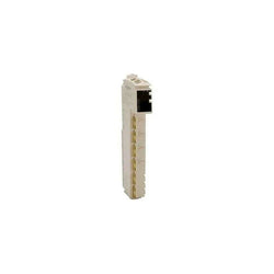
This product is part of the Modicon X80 range, a common platform of modules for Modicon M580 and M340 Programmable Automation Controllers (PAC). This line terminator for rack end is a connection accessory of programmable automation controller modules. This product is composed with one 9-way SUB-D connector labelled A and one 9-way SUB-D connector labelled B. It weighs 0.05kg. It is suitable for process and machine safety functions like emergency shut down, fire and gas, burner or boiler management, control access for safety machines, material handling and turbo machinery. This product is compatible for use with TSXRKYxxEX rock end. The set includes 2 pieces. Reduces maintenance and training costs, same spare parts in stock, unique training for different Programmable Automation Controllers (PAC).
Main
| Characteristic | Value(s) |
|---|---|
| Range of Product | Modicon Premium Automation platform |
| Accessory / separate part category | Connection accessories |
| Accessory / Separate Part Type | Line terminator |
| Accessory / separate part designation | Line terminators |
| Accessory / separate part destination | Rack end |
| Quantity per Set | Set of 2 |
Complementary
| Characteristic | Value(s) |
|---|---|
| Product Compatibility | TSXRKY..EX. |
| Kit composition | 1 connector SUB-D 9 labelled A 1 connector SUB-D 9 labelled B |
| Product Weight | 0.11 lb(US) (0.05 kg) |