
 1 year warranty

Ordering
1 piece
85365080
Popular Downloads
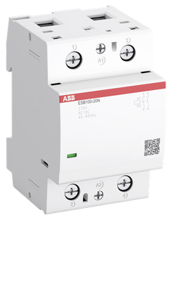
Dimensions
54 mm
65 mm
85 mm
0.405 kg
Technical
2
0
0
0
2P
IEC/EN 60947-1
IEC/EN 60947-4-1
IEC/EN 61095
UL 60947-1
UL 60947-4-1
IEC/EN 60947-1
IEC/EN 60947-4-1
IEC/EN 61095
UL 60947-1
UL 60947-4-1
Main Circuit 220 V DC
Main Circuit 400 V AC
Main Circuit 220 V DC
Main Circuit 400 V AC
Control Circuit 400 Hz
Control Circuit 50 Hz
Control Circuit 60 Hz
Control Circuit DC
Main Circuit 50 Hz
Main Circuit 60 Hz
Main Circuit DC
Control Circuit 400 Hz
Control Circuit 50 Hz
Control Circuit 60 Hz
Control Circuit DC
Main Circuit 50 Hz
Main Circuit 60 Hz
Main Circuit DC
(NO) 100 A
(NO) 100 A
(230 V) Single Phase, NO 23 kW
(230 V) Single Phase, NO 23 kW
500 V
6 kV
AC-1 (NO) 50000 cycle
AC-7a (NO) 50000 cycle
AC-1 (NO) 50000 cycle
AC-7a (NO) 50000 cycle
(AC-1) 150 cycles per hour
(AC-7a) 150 cycles per hour
(AC-1) 150 cycles per hour
(AC-7a) 150 cycles per hour
Nr. Operations 1000000 cycle
(acc. to IEC 60947-4-1) 0.85 ... 1.1 x Uc (at θ ≤ 55 °C)
24 V
Average Holding Value 50 / 60 Hz 7.5 V·A
Average Holding Value DC 8.5 W
Average Pull-in Value 50 Hz 90 V·A
Average Pull-in Value 60 Hz 90 V·A
Average Pull-in Value DC 100 W
Average Holding Value 50 / 60 Hz 7.5 V·A
Average Holding Value DC 8.5 W
Average Pull-in Value 50 Hz 90 V·A
Average Pull-in Value 60 Hz 90 V·A
Average Pull-in Value DC 100 W
at Rated Operating Conditions per Pole 1.9 W
at Rated Operating Conditions AC-1 per Pole 6 W
at Rated Operating Conditions per Pole 1.9 W
at Rated Operating Conditions AC-1 per Pole 6 W
TH35-15 (35 x 15 mm Mounting Rail) acc. to IEC 60715
TH35-7.5 (35 x 7.5 mm Mounting Rail) acc. to IEC 60715
TH35-15 (35 x 15 mm Mounting Rail) acc. to IEC 60715
TH35-7.5 (35 x 7.5 mm Mounting Rail) acc. to IEC 60715
Flexible with Ferrule 1x 10 ... 35 mm²
Flexible with Insulated Ferrule 1x 10 ... 35 mm²
Flexible 1x 10 ... 35 mm²
Rigid 1x 10 ... 50 mm²
Flexible with Ferrule 1x 10 ... 35 mm²
Flexible with Insulated Ferrule 1x 10 ... 35 mm²
Flexible 1x 10 ... 35 mm²
Rigid 1x 10 ... 50 mm²
Flexible with Ferrule 1x 1 ... 2.5 mm²
Flexible with Ferrule 2x 0.75 ... 1.5 mm²
Flexible with Insulated Ferrule 1x 1 ... 2.5 mm²
Flexible with Insulated Ferrule 2x 0.75 ... 1 mm²
Flexible 1x 1 ... 2.5 mm²
Flexible 2x 1 ... 1.5 mm²
Rigid 1x 1 ... 4 mm²
Rigid 2x 1 ... 2.5 mm²
Flexible with Ferrule 1x 1 ... 2.5 mm²
Flexible with Ferrule 2x 0.75 ... 1.5 mm²
Flexible with Insulated Ferrule 1x 1 ... 2.5 mm²
Flexible with Insulated Ferrule 2x 0.75 ... 1 mm²
Flexible 1x 1 ... 2.5 mm²
Flexible 2x 1 ... 1.5 mm²
Rigid 1x 1 ... 4 mm²
Rigid 2x 1 ... 2.5 mm²
Control Circuit 7 mm
Main Circuit 15 mm
Control Circuit 7 mm
Main Circuit 15 mm
IP20
Control Circuit Pozidriv 1
Main Circuit Pozidriv 2
Control Circuit Pozidriv 1
Main Circuit Pozidriv 2
Control Circuit 0.9 N·m
Main Circuit 3 N·m
Control Circuit 0.9 N·m
Main Circuit 3 N·m
Screw Terminals
3.0
Installation Contactors
Technical UL/CSA
Main Circuit 480 V AC
(acc. to UL 480 V) 100 A
Solid 8-0 AWG
Stranded 8-0 AWG
Solid 8-0 AWG
Stranded 8-0 AWG
Solid 16-10 AWG
Stranded 16-10 AWG
Solid 16-10 AWG
Stranded 16-10 AWG
Control Circuit 8 in·lb
Main Circuit 27 in·lb
Control Circuit 8 in·lb
Main Circuit 27 in·lb
Environmental
Operation -25 ... +55 °C
Storage -40 ... +80 °C
Operation -25 ... +55 °C
Storage -40 ... +80 °C
2000 m
11 ms Pulse 15g
3
Material Compliance
Following EU Directive 2011/65/EU and Amendment 2015/863 July 22, 2019
Business To Consumer
5. Small Equipment (No External Dimension More Than 50 cm)
ABB EcoSolutions
Certificates and Declarations
Container Information
box 1 piece
92 mm
57 mm
69.5 mm
0.405 kg
4013614533013
External Classifications and Standards
Q
EC001653 - Installation contactor for distribution board
EC001653 - Installation contactor for distribution board
EC001653 - Installation contactor for distribution board
V11.0 : 27142308
39121529
4759 >> Installation contactor for distribution board
3707599
3210574

Ordering
1 piece
85364900
Popular Downloads
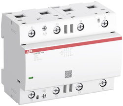
Dimensions
45 mm
77 mm
86 mm
0.31 kg
Technical
3
0
0
1
3P
IEC/EN 60947-1, IEC/EN 60947-4-1, UL 60335-2-40 LZGH2 A2L, UL 60947-4-1, CSA C22.2 No. 60335-2-40 LZGH2 A2L, CSA C22.2 No. 60947-4-1
Auxiliary Circuit 690 V
Main Circuit 690 V
Auxiliary Circuit 690 V
Main Circuit 690 V
Auxiliary Circuit 50 / 60 Hz
Main Circuit 50 / 60 Hz
Auxiliary Circuit 50 / 60 Hz
Main Circuit 50 / 60 Hz
acc. to IEC 60947-4-1, Open Contactors Θ = 40 °C 35 A
acc. to IEC 60947-5-1, Θ = 40 °C 16 A
acc. to IEC 60947-4-1, Open Contactors Θ = 40 °C 35 A
acc. to IEC 60947-5-1, Θ = 40 °C 16 A
(690 V) 40 °C 28 A
(690 V) 60 °C 28 A
(690 V) 70 °C 24 A
(690 V) 40 °C 28 A
(690 V) 60 °C 28 A
(690 V) 70 °C 24 A
(415 V) 60 °C 12 A
(440 V) 60 °C 12 A
(500 V) 60 °C 12.5 A
(690 V) 60 °C 9 A
(380 / 400 V) 60 °C 12 A
(220 / 230 / 240 V) 60 °C 12 A
(415 V) 60 °C 12 A
(440 V) 60 °C 12 A
(500 V) 60 °C 12.5 A
(690 V) 60 °C 9 A
(380 / 400 V) 60 °C 12 A
(220 / 230 / 240 V) 60 °C 12 A
(415 V) 60 °C 12 A
(440 V) 60 °C 12 A
(500 V) 60 °C 12.5 A
(690 V) 60 °C 9 A
(380 / 400 V) 60 °C 12 A
(220 / 230 / 240 V) 60 °C 12 A
(415 V) 60 °C 12 A
(440 V) 60 °C 12 A
(500 V) 60 °C 12.5 A
(690 V) 60 °C 9 A
(380 / 400 V) 60 °C 12 A
(220 / 230 / 240 V) 60 °C 12 A
(500 V) 2 A
(690 V) 2 A
(24 / 127 V) 6 A
(220 / 240 V) 4 A
(400 / 440 V) 3 A
(500 V) 2 A
(690 V) 2 A
(24 / 127 V) 6 A
(220 / 240 V) 4 A
(400 / 440 V) 3 A
(110 V) 1-Pole, 40 °C 15 A
(110 V) 1-Pole, 60 °C 15 A
(110 V) 1-Pole, 70 °C 15 A
(110 V) 2 Poles in Series, 40 °C 27 A
(110 V) 2 Poles in Series, 60 °C 27 A
(110 V) 2 Poles in Series, 70 °C 24 A
(110 V) 3 Poles in Series, 40 °C 27 A
(110 V) 3 Poles in Series, 60 °C 27 A
(110 V) 3 Poles in Series, 70 °C 24 A
(220 V) 2 Poles in Series, 40 °C 15 A
(220 V) 2 Poles in Series, 60 °C 15 A
(220 V) 2 Poles in Series, 70 °C 15 A
(220 V) 3 Poles in Series, 40 °C 27 A
(220 V) 3 Poles in Series, 60 °C 27 A
(220 V) 3 Poles in Series, 70 °C 24 A
(72 V) 1-Pole, 40 °C 27 A
(72 V) 1-Pole, 60 °C 27 A
(72 V) 1-Pole, 70 °C 24 A
(72 V) 2 Poles in Series, 40 °C 27 A
(72 V) 2 Poles in Series, 60 °C 27 A
(72 V) 2 Poles in Series, 70 °C 24 A
(72 V) 3 Poles in Series, 40 °C 27 A
(72 V) 3 Poles in Series, 60 °C 27 A
(72 V) 3 Poles in Series, 70 °C 24 A
(110 V) 1-Pole, 40 °C 15 A
(110 V) 1-Pole, 60 °C 15 A
(110 V) 1-Pole, 70 °C 15 A
(110 V) 2 Poles in Series, 40 °C 27 A
(110 V) 2 Poles in Series, 60 °C 27 A
(110 V) 2 Poles in Series, 70 °C 24 A
(110 V) 3 Poles in Series, 40 °C 27 A
(110 V) 3 Poles in Series, 60 °C 27 A
(110 V) 3 Poles in Series, 70 °C 24 A
(220 V) 2 Poles in Series, 40 °C 15 A
(110 V) 1-Pole, 40 °C 7 A
(110 V) 1-Pole, 60 °C 7 A
(110 V) 1-Pole, 70 °C 7 A
(110 V) 2 Poles in Series, 40 °C 27 A
(110 V) 2 Poles in Series, 60 °C 27 A
(110 V) 2 Poles in Series, 70 °C 24 A
(110 V) 3 Poles in Series, 40 °C 27 A
(110 V) 3 Poles in Series, 60 °C 27 A
(110 V) 3 Poles in Series, 70 °C 24 A
(220 V) 2 Poles in Series, 40 °C 7 A
(220 V) 2 Poles in Series, 60 °C 7 A
(220 V) 2 Poles in Series, 70 °C 7 A
(220 V) 3 Poles in Series, 40 °C 27 A
(220 V) 3 Poles in Series, 60 °C 27 A
(220 V) 3 Poles in Series, 70 °C 24 A
(72 V) 1-Pole, 40 °C 27 A
(72 V) 1-Pole, 60 °C 27 A
(72 V) 1-Pole, 70 °C 24 A
(72 V) 2 Poles in Series, 40 °C 27 A
(72 V) 2 Poles in Series, 60 °C 27 A
(72 V) 2 Poles in Series, 70 °C 24 A
(72 V) 3 Poles in Series, 40 °C 27 A
(72 V) 3 Poles in Series, 60 °C 27 A
(72 V) 3 Poles in Series, 70 °C 24 A
(110 V) 1-Pole, 40 °C 7 A
(110 V) 1-Pole, 60 °C 7 A
(110 V) 1-Pole, 70 °C 7 A
(110 V) 2 Poles in Series, 40 °C 27 A
(110 V) 2 Poles in Series, 60 °C 27 A
(110 V) 2 Poles in Series, 70 °C 24 A
(110 V) 3 Poles in Series, 40 °C 27 A
(110 V) 3 Poles in Series, 60 °C 27 A
(110 V) 3 Poles in Series, 70 °C 24 A
(220 V) 2 Poles in Series, 40 °C 7 A
(110 V) 1-Pole, 40 °C 4 A
(110 V) 1-Pole, 60 °C 4 A
(110 V) 1-Pole, 70 °C 4 A
(110 V) 2 Poles in Series, 40 °C 15 A
(110 V) 2 Poles in Series, 60 °C 15 A
(110 V) 2 Poles in Series, 70 °C 15 A
(110 V) 3 Poles in Series, 40 °C 27 A
(110 V) 3 Poles in Series, 60 °C 27 A
(110 V) 3 Poles in Series, 70 °C 24 A
(220 V) 2 Poles in Series, 40 °C 4 A
(220 V) 2 Poles in Series, 60 °C 4 A
(220 V) 2 Poles in Series, 70 °C 4 A
(220 V) 3 Poles in Series, 40 °C 12 A
(220 V) 3 Poles in Series, 60 °C 12 A
(220 V) 3 Poles in Series, 70 °C 12 A
(72 V) 1-Pole, 40 °C 12 A
(72 V) 1-Pole, 60 °C 12 A
(72 V) 1-Pole, 70 °C 12 A
(72 V) 2 Poles in Series, 40 °C 27 A
(72 V) 2 Poles in Series, 60 °C 27 A
(72 V) 2 Poles in Series, 70 °C 24 A
(72 V) 3 Poles in Series, 40 °C 27 A
(72 V) 3 Poles in Series, 60 °C 27 A
(72 V) 3 Poles in Series, 70 °C 24 A
(110 V) 1-Pole, 40 °C 4 A
(110 V) 1-Pole, 60 °C 4 A
(110 V) 1-Pole, 70 °C 4 A
(110 V) 2 Poles in Series, 40 °C 15 A
(110 V) 2 Poles in Series, 60 °C 15 A
(110 V) 2 Poles in Series, 70 °C 15 A
(110 V) 3 Poles in Series, 40 °C 27 A
(110 V) 3 Poles in Series, 60 °C 27 A
(110 V) 3 Poles in Series, 70 °C 24 A
(220 V) 2 Poles in Series, 40 °C 4 A
(24 V) 6 A / 144 W
(48 V) 2.8 A / 134 W
(72 V) 1 A / 72 W
(110 V) 0.55 A / 60 W
(125 V) 0.55 A / 69 W
(220 V) 0.27 A / 60 W
(250 V) 0.27 A / 68 W
(400 V) 0.15 A / 60 W
(500 V) 0.13 A / 65 W
(600 V) 0.1 A / 60 W
(24 V) 6 A / 144 W
(48 V) 2.8 A / 134 W
(72 V) 1 A / 72 W
(110 V) 0.55 A / 60 W
(125 V) 0.55 A / 69 W
(220 V) 0.27 A / 60 W
(250 V) 0.27 A / 68 W
(400 V) 0.15 A / 60 W
(500 V) 0.13 A / 65 W
(600 V) 0.1 A / 60 W
(400 V) 5.5 kW
(415 V) 5.5 kW
(440 V) 5.5 kW
(500 V) 7.5 kW
(690 V) 7.5 kW
(380 / 400 V) 5.5 kW
(220 / 230 / 240 V) 3 kW
(400 V) 5.5 kW
(415 V) 5.5 kW
(440 V) 5.5 kW
(500 V) 7.5 kW
(690 V) 7.5 kW
(380 / 400 V) 5.5 kW
(220 / 230 / 240 V) 3 kW
(415 V) 5.5 kW
(440 V) 5.5 kW
(500 V) 7.5 kW
(690 V) 7.5 kW
(380 / 400 V) 5.5 kW
(220 / 230 / 240 V) 3 kW
(415 V) 5.5 kW
(440 V) 5.5 kW
(500 V) 7.5 kW
(690 V) 7.5 kW
(380 / 400 V) 5.5 kW
(220 / 230 / 240 V) 3 kW
at 40 °C Ambient Temp, in Free Air, from a Cold State 10 s 150 A
at 40 °C Ambient Temp, in Free Air, from a Cold State 15 min 35 A
at 40 °C Ambient Temp, in Free Air, from a Cold State 1 min 60 A
at 40 °C Ambient Temp, in Free Air, from a Cold State 1 s 300 A
at 40 °C Ambient Temp, in Free Air, from a Cold State 30 s 80 A
for 0.1 s 140 A
for 1 s 100 A
cos phi=0.45 (cos phi=0.35 for Ie > 100 A) at 440 V 250 A
cos phi=0.45 (cos phi=0.35 for Ie > 100 A) at 690 V 106 A
cos phi=0.45 (cos phi=0.35 for Ie > 100 A) at 440 V 250 A
cos phi=0.45 (cos phi=0.35 for Ie > 100 A) at 690 V 106 A
acc. to IEC 60947-4-1 690 V
acc. to IEC 60947-5-1 690 V
acc. to UL/CSA 600 V
acc. to IEC 60947-4-1 690 V
acc. to IEC 60947-5-1 690 V
acc. to UL/CSA 600 V
6 kV
(AC-1) 600 cycles per hour
(AC-15) 1200 cycles per hour
(AC-2 / AC-4) 300 cycles per hour
(AC-3) 1200 cycles per hour
(DC-13) 900 cycles per hour
(AC-1) 600 cycles per hour
(AC-15) 1200 cycles per hour
(AC-2 / AC-4) 300 cycles per hour
(AC-3) 1200 cycles per hour
(DC-13) 900 cycles per hour
3600 cycles per hour
DC Operation 12 ... 20 V
at 6 A per Pole 0.1 W
at Rated Operating Conditions AC-1 per Pole 1 W
at Rated Operating Conditions AC-3 per Pole 0.2 W
at 6 A per Pole 0.1 W
at Rated Operating Conditions AC-1 per Pole 1 W
at Rated Operating Conditions AC-3 per Pole 0.2 W
Between Coil De-energization and NC Contact Closing 13 ... 98 ms
Between Coil De-energization and NO Contact Opening 11 ... 95 ms
Between Coil Energization and NC Contact Opening 38 ... 90 ms
Between Coil Energization and NO Contact Closing 40 ... 95 ms
Between Coil De-energization and NC Contact Closing 13 ... 98 ms
Between Coil De-energization and NO Contact Opening 11 ... 95 ms
Between Coil Energization and NC Contact Opening 38 ... 90 ms
Between Coil Energization and NO Contact Closing 40 ... 95 ms
TH35-15 (35 x 15 mm Mounting Rail) acc. to IEC 60715
TH35-7.5 (35 x 7.5 mm Mounting Rail) acc. to IEC 60715
TH35-15 (35 x 15 mm Mounting Rail) acc. to IEC 60715
TH35-7.5 (35 x 7.5 mm Mounting Rail) acc. to IEC 60715
2 x M4 Screws Placed Diagonally
Flexible with Ferrule 1/2x 0.75 ... 6 mm²
Flexible with Insulated Ferrule 1x 0.75 ... 4 mm²
Flexible with Insulated Ferrule 2x 0.75 ... 2.5 mm²
Rigid Solid 1/2x 1 ... 4 mm²
Rigid Stranded 1/2x 1 ... 6 mm²
Flexible with Ferrule 1/2x 0.75 ... 6 mm²
Flexible with Insulated Ferrule 1x 0.75 ... 4 mm²
Flexible with Insulated Ferrule 2x 0.75 ... 2.5 mm²
Rigid Solid 1/2x 1 ... 4 mm²
Rigid Stranded 1/2x 1 ... 6 mm²
Flexible with Ferrule 1/2x 0.75 ... 2.5 mm²
Flexible with Insulated Ferrule 2x 0.75 ... 1.5 mm²
Flexible with Insulated Ferrule 1x 0.75 ... 2.5 mm²
Rigid Solid 1/2x 1 ... 2.5 mm²
Rigid Stranded 1/2x 1 ... 2.5 mm²
Flexible with Ferrule 1/2x 0.75 ... 2.5 mm²
Flexible with Insulated Ferrule 2x 0.75 ... 1.5 mm²
Flexible with Insulated Ferrule 1x 0.75 ... 2.5 mm²
Rigid Solid 1/2x 1 ... 2.5 mm²
Rigid Stranded 1/2x 1 ... 2.5 mm²
Flexible with Ferrule 1/2x 0.75 ... 2.5 mm²
Flexible with Insulated Ferrule 1x 0.75 ... 2.5 mm²
Flexible with Insulated Ferrule 2x 0.75 ... 1.5 mm²
Rigid Solid 1/2x 1 ... 2.5 mm²
Rigid Stranded 1/2x 1 ... 2.5 mm²
Flexible with Ferrule 1/2x 0.75 ... 2.5 mm²
Flexible with Insulated Ferrule 1x 0.75 ... 2.5 mm²
Flexible with Insulated Ferrule 2x 0.75 ... 1.5 mm²
Rigid Solid 1/2x 1 ... 2.5 mm²
Rigid Stranded 1/2x 1 ... 2.5 mm²
Auxiliary Circuit 10 mm
Control Circuit 10 mm
Main Circuit 10 mm
Auxiliary Circuit 10 mm
Control Circuit 10 mm
Main Circuit 10 mm
acc. to IEC 60529, IEC 60947-1, EN 60529 Auxiliary Terminals IP20
acc. to IEC 60529, IEC 60947-1, EN 60529 Coil Terminals IP20
acc. to IEC 60529, IEC 60947-1, EN 60529 Main Terminals IP20
acc. to IEC 60529, IEC 60947-1, EN 60529 Auxiliary Terminals IP20
acc. to IEC 60529, IEC 60947-1, EN 60529 Coil Terminals IP20
acc. to IEC 60529, IEC 60947-1, EN 60529 Main Terminals IP20
Auxiliary Circuit 1.2 N·m
Control Circuit 1.2 N·m
Main Circuit 1.5 N·m
Auxiliary Circuit 1.2 N·m
Control Circuit 1.2 N·m
Main Circuit 1.5 N·m
Screw Terminals
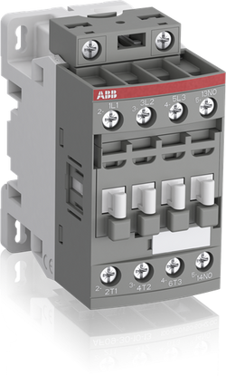
Block Contactor
Technical UL/CSA
0
18 A
(115 V AC) Single Phase 1 Hp
(200 V AC) Three Phase 3 Hp
(230 V AC) Single Phase 2 Hp
(230 V AC) Three Phase 3 Hp
(460 V AC) Three Phase 5 Hp
(575 V AC) Three Phase 5 Hp
(115 V AC) Single Phase 1 Hp
(200 V AC) Three Phase 3 Hp
(230 V AC) Single Phase 2 Hp
(230 V AC) Three Phase 3 Hp
(460 V AC) Three Phase 5 Hp
(575 V AC) Three Phase 5 Hp
Main Circuit 600 V
(600 V AC) 28 A
(120 V AC) Single Phase 1 hp
(200 ... 208 V AC) Three Phase 3 hp
(220 ... 240 V AC) Three Phase 3 hp
(240 V AC) Single Phase 2 hp
(440 ... 480 V AC) Three Phase 7-1/2 hp
(550 ... 600 V AC) Three Phase 10 hp
(120 V AC) Single Phase 1 hp
(200 ... 208 V AC) Three Phase 3 hp
(220 ... 240 V AC) Three Phase 3 hp
(240 V AC) Single Phase 2 hp
(440 ... 480 V AC) Three Phase 7-1/2 hp
(550 ... 600 V AC) Three Phase 10 hp
Rigid Solid 1/2x 16-10 AWG
Rigid Stranded 1/2x 16-10 AWG
Rigid Solid 1/2x 16-10 AWG
Rigid Stranded 1/2x 16-10 AWG
Rigid Solid 1/2x 18-14 AWG
Rigid Stranded 1/2x 18-14 AWG
Rigid Solid 1/2x 18-14 AWG
Rigid Stranded 1/2x 18-14 AWG
Rigid Solid 1/2x 18-14 AWG
Rigid Stranded 1/2x 18-14 AWG
Rigid Solid 1/2x 18-14 AWG
Rigid Stranded 1/2x 18-14 AWG
Auxiliary Circuit 11 in·lb
Control Circuit 11 in·lb
Main Circuit 13 in·lb
Auxiliary Circuit 11 in·lb
Control Circuit 11 in·lb
Main Circuit 13 in·lb
(120 V AC) Single Phase 16 A
(200 ... 208 V AC) Three Phase 11 A
(220 ... 240 V AC) Three Phase 9.6 A
(240 V AC) Single Phase 12 A
(440 ... 480 V AC) Three Phase 11 A
(550 ... 600 V AC) Three Phase 11 A
(120 V AC) Single Phase 16 A
(200 ... 208 V AC) Three Phase 11 A
(220 ... 240 V AC) Three Phase 9.6 A
(240 V AC) Single Phase 12 A
(440 ... 480 V AC) Three Phase 11 A
(550 ... 600 V AC) Three Phase 11 A
Environmental
Close to Contactor Fitted with Thermal O/L Relay -25 ... 60 °C
Close to Contactor without Thermal O/L Relay -40 ... 70 °C
Close to Contactor for Storage -60 ... +80 °C
Close to Contactor Fitted with Thermal O/L Relay -25 ... 60 °C
Close to Contactor without Thermal O/L Relay -40 ... 70 °C
Close to Contactor for Storage -60 ... +80 °C
Category B according to IEC 60947-1 Annex Q
Without Derating 3000 m
Closed, Shock Direction: B1 25 g
Open, Shock Direction: B1 5 g
Shock Direction: A 30 g
Shock Direction: B2 15 g
Shock Direction: C1 25 g
Shock Direction: C2 25 g
Closed, Shock Direction: B1 25 g
Open, Shock Direction: B1 5 g
Shock Direction: A 30 g
Shock Direction: B2 15 g
Shock Direction: C1 25 g
Shock Direction: C2 25 g
4g Closed Position & 2g Open position 5 ... 300 Hz
3
Material Compliance
Following EU Directive 2011/65/EU and Amendment 2015/863 July 22, 2019
Business To Business
5. Small Equipment (No External Dimension More Than 50 cm)
ABB EcoSolutions
Recycled Cardboard - 86 %
Recycled Metal - 28 %
Certificates and Declarations
Container Information
box 1 piece
87 mm
79 mm
47 mm
0.31 kg
3471523113602
box 27 piece
250 mm
300 mm
315 mm
8.37 kg
External Classifications and Standards
Q
EC000066 - Power contactor, AC switching
EC000066 - Power contactor, AC switching
EC000066 - Power contactor, AC switching
V11.0 : 27371003
39121529
4758 >> Iec Contactors
3706234

Ordering
1 piece
85365080
Popular Downloads
Dimensions
108 mm
65 mm
85 mm
0.81 kg
Technical
4
0
0
0
4P
IEC/EN 60947-1
IEC/EN 60947-4-1
IEC/EN 61095
UL 60947-1
UL 60947-4-1
IEC/EN 60947-1
IEC/EN 60947-4-1
IEC/EN 61095
UL 60947-1
UL 60947-4-1
Main Circuit 220 V DC
Main Circuit 400 V AC
Main Circuit 220 V DC
Main Circuit 400 V AC
Control Circuit 400 Hz
Control Circuit 50 Hz
Control Circuit 60 Hz
Control Circuit DC
Main Circuit 50 Hz
Main Circuit 60 Hz
Main Circuit DC
Control Circuit 400 Hz
Control Circuit 50 Hz
Control Circuit 60 Hz
Control Circuit DC
Main Circuit 50 Hz
Main Circuit 60 Hz
Main Circuit DC
(NO) 100 A
(NO) 100 A
(230 V) Single Phase, NO 23 kW
(400 V) Three Phase, NO 69.3 kW
(230 V) Single Phase, NO 23 kW
(400 V) Three Phase, NO 69.3 kW
(230 V) Single Phase, NO 23 kW
500 V
6 kV
AC-1 (NO) 50000 cycle
AC-7a (NO) 50000 cycle
AC-1 (NO) 50000 cycle
AC-7a (NO) 50000 cycle
(AC-1) 150 cycles per hour
(AC-7a) 150 cycles per hour
(AC-1) 150 cycles per hour
(AC-7a) 150 cycles per hour
Nr. Operations 1000000 cycle
(acc. to IEC 60947-4-1) 0.85 ... 1.1 x Uc (at θ ≤ 55 °C)
24 V
Average Holding Value 50 / 60 Hz 7.5 V·A
Average Holding Value DC 8.5 W
Average Pull-in Value 50 Hz 90 V·A
Average Pull-in Value 60 Hz 90 V·A
Average Pull-in Value DC 100 W
Average Holding Value 50 / 60 Hz 7.5 V·A
Average Holding Value DC 8.5 W
Average Pull-in Value 50 Hz 90 V·A
Average Pull-in Value 60 Hz 90 V·A
Average Pull-in Value DC 100 W
at Rated Operating Conditions per Pole 4.2 W
at Rated Operating Conditions AC-1 per Pole 6 W
at Rated Operating Conditions per Pole 4.2 W
at Rated Operating Conditions AC-1 per Pole 6 W
TH35-15 (35 x 15 mm Mounting Rail) acc. to IEC 60715
TH35-7.5 (35 x 7.5 mm Mounting Rail) acc. to IEC 60715
TH35-15 (35 x 15 mm Mounting Rail) acc. to IEC 60715
TH35-7.5 (35 x 7.5 mm Mounting Rail) acc. to IEC 60715
Flexible with Ferrule 1x 10 ... 35 mm²
Flexible with Insulated Ferrule 1x 10 ... 35 mm²
Flexible 1x 10 ... 35 mm²
Rigid 1x 10 ... 50 mm²
Flexible with Ferrule 1x 10 ... 35 mm²
Flexible with Insulated Ferrule 1x 10 ... 35 mm²
Flexible 1x 10 ... 35 mm²
Rigid 1x 10 ... 50 mm²
Flexible with Ferrule 1x 1 ... 2.5 mm²
Flexible with Ferrule 2x 0.75 ... 1.5 mm²
Flexible with Insulated Ferrule 1x 1 ... 2.5 mm²
Flexible with Insulated Ferrule 2x 0.75 ... 1 mm²
Flexible 1x 1 ... 2.5 mm²
Flexible 2x 1 ... 1.5 mm²
Rigid 1x 1 ... 4 mm²
Rigid 2x 1 ... 2.5 mm²
Flexible with Ferrule 1x 1 ... 2.5 mm²
Flexible with Ferrule 2x 0.75 ... 1.5 mm²
Flexible with Insulated Ferrule 1x 1 ... 2.5 mm²
Flexible with Insulated Ferrule 2x 0.75 ... 1 mm²
Flexible 1x 1 ... 2.5 mm²
Flexible 2x 1 ... 1.5 mm²
Rigid 1x 1 ... 4 mm²
Rigid 2x 1 ... 2.5 mm²
Control Circuit 7 mm
Main Circuit 15 mm
Control Circuit 7 mm
Main Circuit 15 mm
IP20
Control Circuit Pozidriv 1
Main Circuit Pozidriv 2
Control Circuit Pozidriv 1
Main Circuit Pozidriv 2
Control Circuit 0.9 N·m
Main Circuit 3 N·m
Control Circuit 0.9 N·m
Main Circuit 3 N·m
Screw Terminals
6.0
Installation Contactors
Technical UL/CSA
Main Circuit 480 V AC
(acc. to UL 480 V) 100 A
Solid 8-0 AWG
Stranded 8-0 AWG
Solid 8-0 AWG
Stranded 8-0 AWG
Solid 16-10 AWG
Stranded 16-10 AWG
Solid 16-10 AWG
Stranded 16-10 AWG
Control Circuit 8 in·lb
Main Circuit 27 in·lb
Control Circuit 8 in·lb
Main Circuit 27 in·lb
Environmental
Operation -25 ... +55 °C
Storage -40 ... +80 °C
Operation -25 ... +55 °C
Storage -40 ... +80 °C
2000 m
11 ms Pulse 15g
3
Material Compliance
Following EU Directive 2011/65/EU and Amendment 2015/863 July 22, 2019
Business To Consumer
5. Small Equipment (No External Dimension More Than 50 cm)
ABB EcoSolutions
Certificates and Declarations
Container Information
box 1 piece
92.5 mm
115.5 mm
77 mm
0.81 kg
4013614533112
External Classifications and Standards
Q
EC001653 - Installation contactor for distribution board
EC001653 - Installation contactor for distribution board
EC001653 - Installation contactor for distribution board
V11.0 : 27142308
39121529
4759 >> Installation contactor for distribution board
3707597
3210576

Ordering
1 piece
85371091
UMC100.3 DC
Popular Downloads
Dimensions
70 mm
107 mm
106 mm
275 g
Technical
1x 0.2-2.5 mm²
0 mm
1 ... 6
3P
3
Approximately 3 W
24 V DC
Main Circuit 50 Hz
Main Circuit 60 Hz
Supply Circuit DC
Main Circuit 50 Hz
Main Circuit 60 Hz
Supply Circuit DC
Auxiliary Circuit 4 kV
63 A
Main Circuit 690 V AC
Main Circuit 1000 V AC
Main Circuit 690 V AC
Main Circuit 1000 V AC
Pozidriv 1
0.24 ... 63 A
CAN/CSA C22.2 No.60947-1
CAN/CSA C22.2 No.60947-4-1
IEC/EN 60947-1
IEC/EN 60947-4-1
IEC/EN 60947-5-1
IEC/EN 60947-8
UL 508
CAN/CSA C22.2 No.60947-1
CAN/CSA C22.2 No.60947-4-1
IEC/EN 60947-1
IEC/EN 60947-4-1
IEC/EN 60947-5-1
IEC/EN 60947-8
UL 508
Screw Terminals
Auxiliary Circuit 0.5 N·m
Control Circuit 0.5 N·m
Auxiliary Circuit 0.5 N·m
Control Circuit 0.5 N·m
class 5E
class 10E
class 20E
class 30E
class 40E
class 5E
class 10E
class 20E
class 30E
class 40E
7 mm
Technical UL/CSA
1x 28-12 AWG
Auxiliary Circuit 230 V AC/DC
Main Circuit 600 V AC
Auxiliary Circuit 230 V AC/DC
Main Circuit 600 V AC
Auxiliary Circuit 8 in·lb
Control Circuit 8 in·lb
Auxiliary Circuit 8 in·lb
Control Circuit 8 in·lb
Environmental
Operation 0 ... +60 °C
Storage -25 ... +70 °C
Operation 0 ... +60 °C
Storage -25 ... +70 °C
IP20
Without Derating 2000 m
15g 1 shock 11 ms
4g 2 ... 100 Hz
Material Compliance
Following EU Directive 2011/65/EU and Amendment 2015/863 July 22, 2019
Business To Business
5. Small Equipment (No External Dimension More Than 50 cm)
Certificates and Declarations
Container Information
box 1 piece
142 mm
122 mm
117 mm
280 g
4013614496912
External Classifications and Standards
V11.0 : 27370804
3709067
4552620
EC002572 - Motor management device
EC002572 - Motor management device
EC002572 - Motor management device
EC002572 - Motor management device
4354 >> Motor control centers
B
39121104
Ordering
1 piece
85365080
Popular Downloads
Dimensions
108 mm
65 mm
85 mm
0.81 kg
Technical
4
0
0
0
4P
IEC/EN 60947-1
IEC/EN 60947-4-1
IEC/EN 61095
UL 60947-1
UL 60947-4-1
IEC/EN 60947-1
IEC/EN 60947-4-1
IEC/EN 61095
UL 60947-1
UL 60947-4-1
Main Circuit 220 V DC
Main Circuit 400 V AC
Main Circuit 220 V DC
Main Circuit 400 V AC
Control Circuit 400 Hz
Control Circuit 50 Hz
Control Circuit 60 Hz
Control Circuit DC
Main Circuit 50 Hz
Main Circuit 60 Hz
Main Circuit DC
Control Circuit 400 Hz
Control Circuit 50 Hz
Control Circuit 60 Hz
Control Circuit DC
Main Circuit 50 Hz
Main Circuit 60 Hz
Main Circuit DC
(NO) 100 A
(NO) 100 A
(230 V) Single Phase, NO 23 kW
(400 V) Three Phase, NO 69.3 kW
(230 V) Single Phase, NO 23 kW
(400 V) Three Phase, NO 69.3 kW
(230 V) Single Phase, NO 23 kW
500 V
6 kV
AC-1 (NO) 50000 cycle
AC-7a (NO) 50000 cycle
AC-1 (NO) 50000 cycle
AC-7a (NO) 50000 cycle
(AC-1) 150 cycles per hour
(AC-7a) 150 cycles per hour
(AC-1) 150 cycles per hour
(AC-7a) 150 cycles per hour
Nr. Operations 1000000 cycle
(acc. to IEC 60947-4-1) 0.85 ... 1.1 x Uc (at θ ≤ 55 °C)
230 V
Average Holding Value 50 / 60 Hz 7.5 V·A
Average Holding Value DC 8.5 W
Average Pull-in Value 50 Hz 90 V·A
Average Pull-in Value 60 Hz 90 V·A
Average Pull-in Value DC 100 W
Average Holding Value 50 / 60 Hz 7.5 V·A
Average Holding Value DC 8.5 W
Average Pull-in Value 50 Hz 90 V·A
Average Pull-in Value 60 Hz 90 V·A
Average Pull-in Value DC 100 W
at Rated Operating Conditions per Pole 4.2 W
at Rated Operating Conditions AC-1 per Pole 6 W
at Rated Operating Conditions per Pole 4.2 W
at Rated Operating Conditions AC-1 per Pole 6 W
TH35-15 (35 x 15 mm Mounting Rail) acc. to IEC 60715
TH35-7.5 (35 x 7.5 mm Mounting Rail) acc. to IEC 60715
TH35-15 (35 x 15 mm Mounting Rail) acc. to IEC 60715
TH35-7.5 (35 x 7.5 mm Mounting Rail) acc. to IEC 60715
Flexible with Ferrule 1x 10 ... 35 mm²
Flexible with Insulated Ferrule 1x 10 ... 35 mm²
Flexible 1x 10 ... 35 mm²
Rigid 1x 10 ... 50 mm²
Flexible with Ferrule 1x 10 ... 35 mm²
Flexible with Insulated Ferrule 1x 10 ... 35 mm²
Flexible 1x 10 ... 35 mm²
Rigid 1x 10 ... 50 mm²
Flexible with Ferrule 1x 1 ... 2.5 mm²
Flexible with Ferrule 2x 0.75 ... 1.5 mm²
Flexible with Insulated Ferrule 1x 1 ... 2.5 mm²
Flexible with Insulated Ferrule 2x 0.75 ... 1 mm²
Flexible 1x 1 ... 2.5 mm²
Flexible 2x 1 ... 1.5 mm²
Rigid 1x 1 ... 4 mm²
Rigid 2x 1 ... 2.5 mm²
Flexible with Ferrule 1x 1 ... 2.5 mm²
Flexible with Ferrule 2x 0.75 ... 1.5 mm²
Flexible with Insulated Ferrule 1x 1 ... 2.5 mm²
Flexible with Insulated Ferrule 2x 0.75 ... 1 mm²
Flexible 1x 1 ... 2.5 mm²
Flexible 2x 1 ... 1.5 mm²
Rigid 1x 1 ... 4 mm²
Rigid 2x 1 ... 2.5 mm²
Control Circuit 7 mm
Main Circuit 15 mm
Control Circuit 7 mm
Main Circuit 15 mm
IP20
Control Circuit Pozidriv 1
Main Circuit Pozidriv 2
Control Circuit Pozidriv 1
Main Circuit Pozidriv 2
Control Circuit 0.9 N·m
Main Circuit 3 N·m
Control Circuit 0.9 N·m
Main Circuit 3 N·m
Screw Terminals
6.0
Installation Contactors
Technical UL/CSA
Main Circuit 480 V AC
(acc. to UL 480 V) 100 A
Solid 8-0 AWG
Stranded 8-0 AWG
Solid 8-0 AWG
Stranded 8-0 AWG
Solid 16-10 AWG
Stranded 16-10 AWG
Solid 16-10 AWG
Stranded 16-10 AWG
Control Circuit 8 in·lb
Main Circuit 27 in·lb
Control Circuit 8 in·lb
Main Circuit 27 in·lb
Environmental
Operation -25 ... +55 °C
Storage -40 ... +80 °C
Operation -25 ... +55 °C
Storage -40 ... +80 °C
2000 m
11 ms Pulse 15g
3
Material Compliance
Following EU Directive 2011/65/EU and Amendment 2015/863 July 22, 2019
Business To Consumer
5. Small Equipment (No External Dimension More Than 50 cm)
ABB EcoSolutions
Certificates and Declarations
Container Information
box 1 piece
92.5 mm
115.5 mm
77 mm
0.81 kg
4013614533211
External Classifications and Standards
Q
EC001653 - Installation contactor for distribution board
EC001653 - Installation contactor for distribution board
EC001653 - Installation contactor for distribution board
V11.0 : 27142308
39121529
4759 >> Installation contactor for distribution board
3707598
3210577
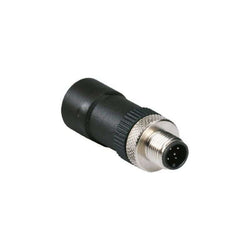
Communication system FBP: Terminating resistor 150 Ohm Profibus

Ordering
1 piece
85365080
Popular Downloads
Dimensions
18 mm
90 mm
75.5 mm
0.1 kg
Technical
Auxiliary Circuit 50 Hz
Auxiliary Circuit 60 Hz
Auxiliary Circuit DC
Auxiliary Circuit 50 Hz
Auxiliary Circuit 60 Hz
Auxiliary Circuit DC
Auxiliary Circuit 6 kV
690 V
48 W
Screw Terminals
Flexible with Ferrule 1/2x 0.75 ... 2.5 mm²
Flexible with Insulated Ferrule 1x 0.75 ... 2.5 mm²
Flexible with Insulated Ferrule 2x 0.75 ... 1.5 mm²
Flexible 1/2x 0.75 ... 2.5 mm²
Rigid 1/2x 1 ... 4 mm²
Flexible with Ferrule 1/2x 0.75 ... 2.5 mm²
Flexible with Insulated Ferrule 1x 0.75 ... 2.5 mm²
Flexible with Insulated Ferrule 2x 0.75 ... 1.5 mm²
Flexible 1/2x 0.75 ... 2.5 mm²
Rigid 1/2x 1 ... 4 mm²
Auxiliary Circuit 0.8 ... 1.2 N·m
Auxiliary Circuit 10 mm
Pozidriv 2
1 ... 6
CSA 22.2 No. 14
IEC/EN 60947-1
IEC/EN 60947-4-1
UL 508
UL 60947-1
UL 60947-4-1
CSA 22.2 No. 14
IEC/EN 60947-1
IEC/EN 60947-4-1
UL 508
UL 60947-1
UL 60947-4-1
Please consider 15 min OFF-period after 5s ON-period.
The mechanical and electrical durability of manual motor starters in combination with UA1/AA1 is reduced. Values are provided on request.
Please consider 15 min OFF-period after 5s ON-period.
The mechanical and electrical durability of manual motor starters in combination with UA1/AA1 is reduced. Values are provided on request.
Technical UL/CSA
Flexible 1/2x 16-12 AWG
Stranded 1/2x 16-12 AWG
Flexible 1/2x 16-12 AWG
Stranded 1/2x 16-12 AWG
Auxiliary Circuit 7 in·lb
Environmental
Operation -25 ... +60 °C
Storage -50 ... +80 °C
Operation -25 ... +60 °C
Storage -50 ... +80 °C
11 ms Pulse 15g
Material Compliance
Following EU Directive 2011/65/EU and Amendment 2015/863 July 22, 2019
Business To Business
5. Small Equipment (No External Dimension More Than 50 cm)
Certificates and Declarations
Container Information
box 1 piece
93 mm
25 mm
80 mm
0.11 kg
4013614343322
carton 80 piece
280 mm
395 mm
210 mm
9.175 kg
4013614526053
External Classifications and Standards
Q
EC001023 - Shunt release (for power circuit breaker)
EC001023 - Shunt release (for power circuit breaker)
V11.0 : 27370418
39121601
4879 >> Shunt release (for power circuit breaker)
3705825
4364017
Ordering
1 piece
85364900
Popular Downloads
Dimensions
45 mm
77 mm
86 mm
0.31 kg
Technical
3
0
1
0
3P
IEC/EN 60947-1, IEC/EN 60947-4-1, UL 60335-2-40 LZGH2 A2L, UL 60947-4-1, CSA C22.2 No. 60335-2-40 LZGH2 A2L, CSA C22.2 No. 60947-4-1
Auxiliary Circuit 690 V
Main Circuit 690 V
Auxiliary Circuit 690 V
Main Circuit 690 V
Auxiliary Circuit 50 / 60 Hz
Control Circuit 50 / 60 Hz
Main Circuit 50 / 60 Hz
Auxiliary Circuit 50 / 60 Hz
Control Circuit 50 / 60 Hz
Main Circuit 50 / 60 Hz
acc. to IEC 60947-4-1, Open Contactors Θ = 40 °C 35 A
acc. to IEC 60947-5-1, Θ = 40 °C 16 A
acc. to IEC 60947-4-1, Open Contactors Θ = 40 °C 35 A
acc. to IEC 60947-5-1, Θ = 40 °C 16 A
(690 V) 40 °C 28 A
(690 V) 60 °C 28 A
(690 V) 70 °C 24 A
(690 V) 40 °C 28 A
(690 V) 60 °C 28 A
(690 V) 70 °C 24 A
(415 V) 60 °C 12 A
(440 V) 60 °C 12 A
(500 V) 60 °C 12.5 A
(690 V) 60 °C 9 A
(380 / 400 V) 60 °C 12 A
(220 / 230 / 240 V) 60 °C 12 A
(415 V) 60 °C 12 A
(440 V) 60 °C 12 A
(500 V) 60 °C 12.5 A
(690 V) 60 °C 9 A
(380 / 400 V) 60 °C 12 A
(220 / 230 / 240 V) 60 °C 12 A
(415 V) 60 °C 12 A
(440 V) 60 °C 12 A
(500 V) 60 °C 12.5 A
(690 V) 60 °C 9 A
(380 / 400 V) 60 °C 12 A
(220 / 230 / 240 V) 60 °C 12 A
(415 V) 60 °C 12 A
(440 V) 60 °C 12 A
(500 V) 60 °C 12.5 A
(690 V) 60 °C 9 A
(380 / 400 V) 60 °C 12 A
(220 / 230 / 240 V) 60 °C 12 A
(500 V) 2 A
(690 V) 2 A
(24 / 127 V) 6 A
(220 / 240 V) 4 A
(400 / 440 V) 3 A
(500 V) 2 A
(690 V) 2 A
(24 / 127 V) 6 A
(220 / 240 V) 4 A
(400 / 440 V) 3 A
(110 V) 1-Pole, 40 °C 15 A
(110 V) 1-Pole, 60 °C 15 A
(110 V) 1-Pole, 70 °C 15 A
(110 V) 2 Poles in Series, 40 °C 27 A
(110 V) 2 Poles in Series, 60 °C 27 A
(110 V) 2 Poles in Series, 70 °C 24 A
(110 V) 3 Poles in Series, 40 °C 27 A
(110 V) 3 Poles in Series, 60 °C 27 A
(110 V) 3 Poles in Series, 70 °C 24 A
(220 V) 2 Poles in Series, 40 °C 15 A
(220 V) 2 Poles in Series, 60 °C 15 A
(220 V) 2 Poles in Series, 70 °C 15 A
(220 V) 3 Poles in Series, 40 °C 27 A
(220 V) 3 Poles in Series, 60 °C 27 A
(220 V) 3 Poles in Series, 70 °C 24 A
(72 V) 1-Pole, 40 °C 27 A
(72 V) 1-Pole, 60 °C 27 A
(72 V) 1-Pole, 70 °C 24 A
(72 V) 2 Poles in Series, 40 °C 27 A
(72 V) 2 Poles in Series, 60 °C 27 A
(72 V) 2 Poles in Series, 70 °C 24 A
(72 V) 3 Poles in Series, 40 °C 27 A
(72 V) 3 Poles in Series, 60 °C 27 A
(72 V) 3 Poles in Series, 70 °C 24 A
(110 V) 1-Pole, 40 °C 15 A
(110 V) 1-Pole, 60 °C 15 A
(110 V) 1-Pole, 70 °C 15 A
(110 V) 2 Poles in Series, 40 °C 27 A
(110 V) 2 Poles in Series, 60 °C 27 A
(110 V) 2 Poles in Series, 70 °C 24 A
(110 V) 3 Poles in Series, 40 °C 27 A
(110 V) 3 Poles in Series, 60 °C 27 A
(110 V) 3 Poles in Series, 70 °C 24 A
(220 V) 2 Poles in Series, 40 °C 15 A
(110 V) 1-Pole, 40 °C 7 A
(110 V) 1-Pole, 60 °C 7 A
(110 V) 1-Pole, 70 °C 7 A
(110 V) 2 Poles in Series, 40 °C 27 A
(110 V) 2 Poles in Series, 60 °C 27 A
(110 V) 2 Poles in Series, 70 °C 24 A
(110 V) 3 Poles in Series, 40 °C 27 A
(110 V) 3 Poles in Series, 60 °C 27 A
(110 V) 3 Poles in Series, 70 °C 24 A
(220 V) 2 Poles in Series, 40 °C 7 A
(220 V) 2 Poles in Series, 60 °C 7 A
(220 V) 2 Poles in Series, 70 °C 7 A
(220 V) 3 Poles in Series, 40 °C 27 A
(220 V) 3 Poles in Series, 60 °C 27 A
(220 V) 3 Poles in Series, 70 °C 24 A
(72 V) 1-Pole, 40 °C 27 A
(72 V) 1-Pole, 60 °C 27 A
(72 V) 1-Pole, 70 °C 24 A
(72 V) 2 Poles in Series, 40 °C 27 A
(72 V) 2 Poles in Series, 60 °C 27 A
(72 V) 2 Poles in Series, 70 °C 24 A
(72 V) 3 Poles in Series, 40 °C 27 A
(72 V) 3 Poles in Series, 60 °C 27 A
(72 V) 3 Poles in Series, 70 °C 24 A
(110 V) 1-Pole, 40 °C 7 A
(110 V) 1-Pole, 60 °C 7 A
(110 V) 1-Pole, 70 °C 7 A
(110 V) 2 Poles in Series, 40 °C 27 A
(110 V) 2 Poles in Series, 60 °C 27 A
(110 V) 2 Poles in Series, 70 °C 24 A
(110 V) 3 Poles in Series, 40 °C 27 A
(110 V) 3 Poles in Series, 60 °C 27 A
(110 V) 3 Poles in Series, 70 °C 24 A
(220 V) 2 Poles in Series, 40 °C 7 A
(110 V) 1-Pole, 40 °C 4 A
(110 V) 1-Pole, 60 °C 4 A
(110 V) 1-Pole, 70 °C 4 A
(110 V) 2 Poles in Series, 40 °C 15 A
(110 V) 2 Poles in Series, 60 °C 15 A
(110 V) 2 Poles in Series, 70 °C 15 A
(110 V) 3 Poles in Series, 40 °C 27 A
(110 V) 3 Poles in Series, 60 °C 27 A
(110 V) 3 Poles in Series, 70 °C 24 A
(220 V) 2 Poles in Series, 40 °C 4 A
(220 V) 2 Poles in Series, 60 °C 4 A
(220 V) 2 Poles in Series, 70 °C 4 A
(220 V) 3 Poles in Series, 40 °C 12 A
(220 V) 3 Poles in Series, 60 °C 12 A
(220 V) 3 Poles in Series, 70 °C 12 A
(72 V) 1-Pole, 40 °C 12 A
(72 V) 1-Pole, 60 °C 12 A
(72 V) 1-Pole, 70 °C 12 A
(72 V) 2 Poles in Series, 40 °C 27 A
(72 V) 2 Poles in Series, 60 °C 27 A
(72 V) 2 Poles in Series, 70 °C 24 A
(72 V) 3 Poles in Series, 40 °C 27 A
(72 V) 3 Poles in Series, 60 °C 27 A
(72 V) 3 Poles in Series, 70 °C 24 A
(110 V) 1-Pole, 40 °C 4 A
(110 V) 1-Pole, 60 °C 4 A
(110 V) 1-Pole, 70 °C 4 A
(110 V) 2 Poles in Series, 40 °C 15 A
(110 V) 2 Poles in Series, 60 °C 15 A
(110 V) 2 Poles in Series, 70 °C 15 A
(110 V) 3 Poles in Series, 40 °C 27 A
(110 V) 3 Poles in Series, 60 °C 27 A
(110 V) 3 Poles in Series, 70 °C 24 A
(220 V) 2 Poles in Series, 40 °C 4 A
(24 V) 6 A / 144 W
(48 V) 2.8 A / 134 W
(72 V) 1 A / 72 W
(110 V) 0.55 A / 60 W
(125 V) 0.55 A / 69 W
(220 V) 0.27 A / 60 W
(250 V) 0.27 A / 68 W
(400 V) 0.15 A / 60 W
(500 V) 0.13 A / 65 W
(600 V) 0.1 A / 60 W
(24 V) 6 A / 144 W
(48 V) 2.8 A / 134 W
(72 V) 1 A / 72 W
(110 V) 0.55 A / 60 W
(125 V) 0.55 A / 69 W
(220 V) 0.27 A / 60 W
(250 V) 0.27 A / 68 W
(400 V) 0.15 A / 60 W
(500 V) 0.13 A / 65 W
(600 V) 0.1 A / 60 W
(400 V) 5.5 kW
(415 V) 5.5 kW
(440 V) 5.5 kW
(500 V) 7.5 kW
(690 V) 7.5 kW
(380 / 400 V) 5.5 kW
(220 / 230 / 240 V) 3 kW
(400 V) 5.5 kW
(415 V) 5.5 kW
(440 V) 5.5 kW
(500 V) 7.5 kW
(690 V) 7.5 kW
(380 / 400 V) 5.5 kW
(220 / 230 / 240 V) 3 kW
(415 V) 5.5 kW
(440 V) 5.5 kW
(500 V) 7.5 kW
(690 V) 7.5 kW
(380 / 400 V) 5.5 kW
(220 / 230 / 240 V) 3 kW
(415 V) 5.5 kW
(440 V) 5.5 kW
(500 V) 7.5 kW
(690 V) 7.5 kW
(380 / 400 V) 5.5 kW
(220 / 230 / 240 V) 3 kW
at 40 °C Ambient Temp, in Free Air, from a Cold State 10 s 150 A
at 40 °C Ambient Temp, in Free Air, from a Cold State 15 min 35 A
at 40 °C Ambient Temp, in Free Air, from a Cold State 1 min 60 A
at 40 °C Ambient Temp, in Free Air, from a Cold State 1 s 300 A
at 40 °C Ambient Temp, in Free Air, from a Cold State 30 s 80 A
for 0.1 s 140 A
for 1 s 100 A
at 40 °C Ambient Temp, in Free Air, from a Cold State 10 s 150 A
at 40 °C Ambient Temp, in Free Air, from a Cold State 15 min 35 A
at 40 °C Ambient Temp, in Free Air, from a Cold State 1 min 60 A
at 40 °C Ambient Temp, in Free Air, from a Cold State 1 s 300 A
at 40 °C Ambient Temp, in Free Air, from a Cold State 30 s 80 A
for 0.1 s 140 A
for 1 s 100 A
cos phi=0.45 (cos phi=0.35 for Ie > 100 A) at 440 V 250 A
cos phi=0.45 (cos phi=0.35 for Ie > 100 A) at 690 V 106 A
cos phi=0.45 (cos phi=0.35 for Ie > 100 A) at 440 V 250 A
cos phi=0.45 (cos phi=0.35 for Ie > 100 A) at 690 V 106 A
acc. to IEC 60947-4-1 690 V
acc. to IEC 60947-5-1 690 V
acc. to UL/CSA 600 V
acc. to IEC 60947-4-1 690 V
acc. to IEC 60947-5-1 690 V
acc. to UL/CSA 600 V
6 kV
(AC-1) 600 cycles per hour
(AC-15) 1200 cycles per hour
(AC-2 / AC-4) 300 cycles per hour
(AC-3) 1200 cycles per hour
(DC-13) 900 cycles per hour
(AC-1) 600 cycles per hour
(AC-15) 1200 cycles per hour
(AC-2 / AC-4) 300 cycles per hour
(AC-3) 1200 cycles per hour
(DC-13) 900 cycles per hour
3600 cycles per hour
50 Hz 24 ... 60 V
60 Hz 24 ... 60 V
DC Operation 20 ... 60 V
50 Hz 24 ... 60 V
60 Hz 24 ... 60 V
DC Operation 20 ... 60 V
at 6 A per Pole 0.1 W
at Rated Operating Conditions AC-1 per Pole 1 W
at Rated Operating Conditions AC-3 per Pole 0.2 W
at 6 A per Pole 0.1 W
at Rated Operating Conditions AC-1 per Pole 1 W
at Rated Operating Conditions AC-3 per Pole 0.2 W
Between Coil De-energization and NC Contact Closing 13 ... 98 ms
Between Coil De-energization and NO Contact Opening 11 ... 95 ms
Between Coil Energization and NC Contact Opening 38 ... 90 ms
Between Coil Energization and NO Contact Closing 40 ... 95 ms
Between Coil De-energization and NC Contact Closing 13 ... 98 ms
Between Coil De-energization and NO Contact Opening 11 ... 95 ms
Between Coil Energization and NC Contact Opening 38 ... 90 ms
Between Coil Energization and NO Contact Closing 40 ... 95 ms
TH35-15 (35 x 15 mm Mounting Rail) acc. to IEC 60715
TH35-7.5 (35 x 7.5 mm Mounting Rail) acc. to IEC 60715
TH35-15 (35 x 15 mm Mounting Rail) acc. to IEC 60715
TH35-7.5 (35 x 7.5 mm Mounting Rail) acc. to IEC 60715
2 x M4 Screws Placed Diagonally
Flexible with Ferrule 1/2x 0.75 ... 6 mm²
Flexible with Insulated Ferrule 1x 0.75 ... 4 mm²
Flexible with Insulated Ferrule 2x 0.75 ... 2.5 mm²
Rigid Solid 1/2x 1 ... 4 mm²
Rigid Stranded 1/2x 1 ... 6 mm²
Flexible with Ferrule 1/2x 0.75 ... 6 mm²
Flexible with Insulated Ferrule 1x 0.75 ... 4 mm²
Flexible with Insulated Ferrule 2x 0.75 ... 2.5 mm²
Rigid Solid 1/2x 1 ... 4 mm²
Rigid Stranded 1/2x 1 ... 6 mm²
Flexible with Ferrule 1/2x 0.75 ... 2.5 mm²
Flexible with Insulated Ferrule 2x 0.75 ... 1.5 mm²
Flexible with Insulated Ferrule 1x 0.75 ... 2.5 mm²
Rigid Solid 1/2x 1 ... 2.5 mm²
Rigid Stranded 1/2x 1 ... 2.5 mm²
Flexible with Ferrule 1/2x 0.75 ... 2.5 mm²
Flexible with Insulated Ferrule 2x 0.75 ... 1.5 mm²
Flexible with Insulated Ferrule 1x 0.75 ... 2.5 mm²
Rigid Solid 1/2x 1 ... 2.5 mm²
Rigid Stranded 1/2x 1 ... 2.5 mm²
Flexible with Ferrule 1/2x 0.75 ... 2.5 mm²
Flexible with Insulated Ferrule 1x 0.75 ... 2.5 mm²
Flexible with Insulated Ferrule 2x 0.75 ... 1.5 mm²
Rigid Solid 1/2x 1 ... 2.5 mm²
Rigid Stranded 1/2x 1 ... 2.5 mm²
Flexible with Ferrule 1/2x 0.75 ... 2.5 mm²
Flexible with Insulated Ferrule 1x 0.75 ... 2.5 mm²
Flexible with Insulated Ferrule 2x 0.75 ... 1.5 mm²
Rigid Solid 1/2x 1 ... 2.5 mm²
Rigid Stranded 1/2x 1 ... 2.5 mm²
Auxiliary Circuit 10 mm
Control Circuit 10 mm
Main Circuit 10 mm
Auxiliary Circuit 10 mm
Control Circuit 10 mm
Main Circuit 10 mm
acc. to IEC 60529, IEC 60947-1, EN 60529 Auxiliary Terminals IP20
acc. to IEC 60529, IEC 60947-1, EN 60529 Coil Terminals IP20
acc. to IEC 60529, IEC 60947-1, EN 60529 Main Terminals IP20
acc. to IEC 60529, IEC 60947-1, EN 60529 Auxiliary Terminals IP20
acc. to IEC 60529, IEC 60947-1, EN 60529 Coil Terminals IP20
acc. to IEC 60529, IEC 60947-1, EN 60529 Main Terminals IP20
Auxiliary Circuit 1.2 N·m
Control Circuit 1.2 N·m
Main Circuit 1.5 N·m
Auxiliary Circuit 1.2 N·m
Control Circuit 1.2 N·m
Main Circuit 1.5 N·m
Screw Terminals
Block Contactor
Technical UL/CSA
0
18 A
(115 V AC) Single Phase 1 Hp
(200 V AC) Three Phase 3 Hp
(230 V AC) Single Phase 2 Hp
(230 V AC) Three Phase 3 Hp
(460 V AC) Three Phase 5 Hp
(575 V AC) Three Phase 5 Hp
(115 V AC) Single Phase 1 Hp
(200 V AC) Three Phase 3 Hp
(230 V AC) Single Phase 2 Hp
(230 V AC) Three Phase 3 Hp
(460 V AC) Three Phase 5 Hp
(575 V AC) Three Phase 5 Hp
Main Circuit 600 V
(600 V AC) 28 A
(120 V AC) Single Phase 1 hp
(200 ... 208 V AC) Three Phase 3 hp
(220 ... 240 V AC) Three Phase 3 hp
(240 V AC) Single Phase 2 hp
(440 ... 480 V AC) Three Phase 7-1/2 hp
(550 ... 600 V AC) Three Phase 10 hp
(120 V AC) Single Phase 1 hp
(200 ... 208 V AC) Three Phase 3 hp
(220 ... 240 V AC) Three Phase 3 hp
(240 V AC) Single Phase 2 hp
(440 ... 480 V AC) Three Phase 7-1/2 hp
(550 ... 600 V AC) Three Phase 10 hp
Rigid Solid 1/2x 16-10 AWG
Rigid Stranded 1/2x 16-10 AWG
Rigid Solid 1/2x 16-10 AWG
Rigid Stranded 1/2x 16-10 AWG
Rigid Solid 1/2x 18-14 AWG
Rigid Stranded 1/2x 18-14 AWG
Rigid Solid 1/2x 18-14 AWG
Rigid Stranded 1/2x 18-14 AWG
Rigid Solid 1/2x 18-14 AWG
Rigid Stranded 1/2x 18-14 AWG
Rigid Solid 1/2x 18-14 AWG
Rigid Stranded 1/2x 18-14 AWG
Auxiliary Circuit 11 in·lb
Control Circuit 11 in·lb
Main Circuit 13 in·lb
Auxiliary Circuit 11 in·lb
Control Circuit 11 in·lb
Main Circuit 13 in·lb
(120 V AC) Single Phase 16 A
(200 ... 208 V AC) Three Phase 11 A
(220 ... 240 V AC) Three Phase 9.6 A
(240 V AC) Single Phase 12 A
(440 ... 480 V AC) Three Phase 11 A
(550 ... 600 V AC) Three Phase 11 A
(120 V AC) Single Phase 16 A
(200 ... 208 V AC) Three Phase 11 A
(220 ... 240 V AC) Three Phase 9.6 A
(240 V AC) Single Phase 12 A
(440 ... 480 V AC) Three Phase 11 A
(550 ... 600 V AC) Three Phase 11 A
Environmental
Close to Contactor Fitted with Thermal O/L Relay -25 ... 60 °C
Close to Contactor without Thermal O/L Relay -40 ... 70 °C
Close to Contactor for Storage -60 ... +80 °C
Close to Contactor Fitted with Thermal O/L Relay -25 ... 60 °C
Close to Contactor without Thermal O/L Relay -40 ... 70 °C
Close to Contactor for Storage -60 ... +80 °C
Category B according to IEC 60947-1 Annex Q
Without Derating 3000 m
Closed, Shock Direction: B1 25 g
Open, Shock Direction: B1 5 g
Shock Direction: A 30 g
Shock Direction: B2 15 g
Shock Direction: C1 25 g
Shock Direction: C2 25 g
Closed, Shock Direction: B1 25 g
Open, Shock Direction: B1 5 g
Shock Direction: A 30 g
Shock Direction: B2 15 g
Shock Direction: C1 25 g
Shock Direction: C2 25 g
4g Closed Position & 2g Open position 5 ... 300 Hz
3
Material Compliance
Following EU Directive 2011/65/EU and Amendment 2015/863 July 22, 2019
20474b0e-7edf-439c-bba5-e1947d335b56 China
Business To Business
5. Small Equipment (No External Dimension More Than 50 cm)
ABB EcoSolutions
Recycled Cardboard - 86 %
Recycled Metal - 28 %
Certificates and Declarations
Container Information
box 1 piece
87 mm
79 mm
47 mm
0.31 kg
3471523113510
box 27 piece
250 mm
300 mm
315 mm
8.37 kg
External Classifications and Standards
Q
EC000066 - Power contactor, AC switching
EC000066 - Power contactor, AC switching
EC000066 - Power contactor, AC switching
V11.0 : 27371003
39121529
4758 >> Iec Contactors
3706231
3211360

A12-30-10 24V 50Hz / 24V 60Hz Contactor
Ordering
1 piece
85362010
Popular Downloads
Dimensions
45 mm
90 mm
85.6 mm
0.225 kg
Technical
(230 V AC) 50 kA
(400 V AC) 50 kA
(440 V AC) 50 kA
(500 V AC) 30 kA
(690 V AC) 30 kA
(230 V AC) 50 kA
(400 V AC) 50 kA
(440 V AC) 50 kA
(500 V AC) 30 kA
(690 V AC) 30 kA
(230 V AC) 100 kA
(400 V AC) 100 kA
(440 V AC) 100 kA
(500 V AC) 100 kA
(690 V AC) 100 kA
(230 V AC) 100 kA
(400 V AC) 100 kA
(440 V AC) 100 kA
(500 V AC) 100 kA
(690 V AC) 100 kA
12.5 A
0.63 ... 1.0 A
(400 V) Three Phase 0.25 kW
(400 V) Three Phase 0.25 kW
Main Circuit 690 V AC
1 A
1 A
1 A
Main Circuit 50 Hz
Main Circuit 60 Hz
Main Circuit 50 Hz
Main Circuit 60 Hz
Main Circuit 6 kV
690 V
at Rated Operating Conditions per Pole 0.6 ... 1.6 W
3P
Main Circuit 1 A
Housing IP20
Main Circuit Terminals IP10
Housing IP20
Main Circuit Terminals IP10
3
100000 cycle
Nr. Operations 100000 cycle
Screw Terminals
Flexible with Ferrule 1/2x 0.75 ... 2.5 mm²
Flexible with Insulated Ferrule 1/2x 0.75 ... 2.5 mm²
Flexible 1/2x 0.75 ... 2.5 mm²
Rigid 1/2x 1 ... 4 mm²
Flexible with Ferrule 1/2x 0.75 ... 2.5 mm²
Flexible with Insulated Ferrule 1/2x 0.75 ... 2.5 mm²
Flexible 1/2x 0.75 ... 2.5 mm²
Rigid 1/2x 1 ... 4 mm²
Main Circuit 0.8 ... 1.2 N·m
Main Circuit 9 mm
Pozidriv 2
1 ... 6
any
1 ... 6
any
TH35-15 (35 x 15 mm Mounting Rail) acc. to IEC 60715
TH35-7.5 (35 x 7.5 mm Mounting Rail) acc. to IEC 60715
TH35-15 (35 x 15 mm Mounting Rail) acc. to IEC 60715
TH35-7.5 (35 x 7.5 mm Mounting Rail) acc. to IEC 60715
Electrical Conductive Board, Horizontal - Up to 400 V 0 mm
Electrical Conductive Board, Horizontal - Up to 690 V 1.5 mm
Electrical Conductive Board, Vertical 75 mm
Other Device Same Type, Horizontal 0 mm
Other Device Same Type, Vertical 150 mm
Electrical Conductive Board, Horizontal - Up to 400 V 0 mm
Electrical Conductive Board, Horizontal - Up to 690 V 1.5 mm
Electrical Conductive Board, Vertical 75 mm
Other Device Same Type, Horizontal 0 mm
Other Device Same Type, Vertical 150 mm
Rotary Handle
ON / OFF
IEC/EN 60947-1
IEC/EN 60947-2
IEC/EN 60947-4-1
UL 60947-1
UL 60947-4-1
IEC 60335-2-40 A2L
IEC/EN 60947-1
IEC/EN 60947-2
IEC/EN 60947-4-1
UL 60947-1
UL 60947-4-1
IEC 60335-2-40 A2L
Technical UL/CSA
Any UL Listed Fuses or Circuit-Breakers, Group Installations (480 V AC) 30 kA
Any UL Listed Fuses or Circuit-Breakers, Group Installations (600 V AC) 5 kA
Any UL Listed Fuses or Circuit-Breakers, Motor Disconnect (480 V AC) 30 kA
Any UL Listed Fuses or Circuit-Breakers, Motor Disconnect (600 V AC) 5 kA
Main Circuit 600 V AC
(550 ... 600 V AC) Three Phase 0.5 Hp
(110 ... 120 V AC) Three Phase 1 A
(200 V AC) Three Phase 1 A
(208 V AC) Three Phase 1 A
(220 ... 240 V AC) Three Phase 1 A
(440 ... 480 V AC) Three Phase 1 A
(550 ... 600 V AC) Three Phase 0.9 A
(110 ... 120 V AC) Three Phase 1 A
(200 V AC) Three Phase 1 A
(208 V AC) Three Phase 1 A
(220 ... 240 V AC) Three Phase 1 A
(440 ... 480 V AC) Three Phase 1 A
(550 ... 600 V AC) Three Phase 0.9 A
(110 ... 120 V AC) Three Phase 6 A
(200 V AC) Three Phase 6 A
(208 V AC) Three Phase 6 A
(220 ... 240 V AC) Three Phase 6 A
(440 ... 480 V AC) Three Phase 6 A
(550 ... 600 V AC) Three Phase 8 A
(110 ... 120 V AC) Three Phase 6 A
(200 V AC) Three Phase 6 A
(208 V AC) Three Phase 6 A
(220 ... 240 V AC) Three Phase 6 A
(440 ... 480 V AC) Three Phase 6 A
(550 ... 600 V AC) Three Phase 8 A
(600 V AC) 1 A
Flexible 1/2x 16-12 AWG
Stranded 1/2x 16-12 AWG
Flexible 1/2x 16-12 AWG
Stranded 1/2x 16-12 AWG
Main Circuit 10 in·lb
Environmental
Around the Enclosure 0 ... +40 °C
Operation -25 ... +70 °C
Operation Compensated -25 ... +55 °C
Storage -50 ... +80 °C
Around the Enclosure 0 ... +40 °C
Operation -25 ... +70 °C
Operation Compensated -25 ... +55 °C
Storage -50 ... +80 °C
Yes
2000 m
11 ms Pulse 25g
2g 5 ... 150 Hz
5g 3 ... 150 Hz
2g 5 ... 150 Hz
5g 3 ... 150 Hz
Material Compliance
Following EU Directive 2011/65/EU and Amendment 2015/863 July 22, 2019
Business To Business
5. Small Equipment (No External Dimension More Than 50 cm)
ABB EcoSolutions
Certificates and Declarations
Container Information
box 1 piece
92 mm
95 mm
50 mm
0.24 kg
4013614320286
carton 40 piece
280 mm
395 mm
210 mm
9.986 kg
4013614408656
External Classifications and Standards
F
EC000074 - Motor protection circuit-breaker
EC000074 - Motor protection circuit-breaker
V11.0 : 27370401
39121521
4731 >> Manual Starters
3706005
4364271
3111938
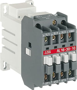
AL12-30-10 24V DC Contactor
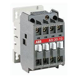
A12-30-10 230-240V 50Hz / 240-260V 60Hz Contactor

Ordering
1 piece
85362010
Popular Downloads
Dimensions
45 mm
97.8 mm
85.4 mm
0.31 kg
Technical
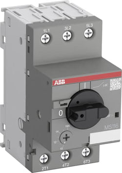
(230 V AC) 10 kA
(400 V AC) 10 kA
(440 V AC) 3 kA
(500 V AC) 3 kA
(690 V AC) 2 kA
(230 V AC) 10 kA
(400 V AC) 10 kA
(440 V AC) 3 kA
(500 V AC) 3 kA
(690 V AC) 2 kA
(230 V AC) 16 kA
(400 V AC) 16 kA
(440 V AC) 15 kA
(500 V AC) 10 kA
(690 V AC) 3 kA
(230 V AC) 16 kA
(400 V AC) 16 kA
(440 V AC) 15 kA
(500 V AC) 10 kA
(690 V AC) 3 kA
300 A
16 ... 20 A
(400 V) Three Phase 7.5 kW
(400 V) Three Phase 7.5 kW
Main Circuit 690 V AC
20 A
20 A
20 A
Main Circuit 50 Hz
Main Circuit 60 Hz
Main Circuit 50 Hz
Main Circuit 60 Hz
Main Circuit 6 kV
690 V
at Rated Operating Conditions per Pole 1.5 ... 2.3 W
3P
Main Circuit 20 A
Housing IP20
Main Circuit Terminals IP10
Housing IP20
Main Circuit Terminals IP10
3
50000 cycle
Nr. Operations 100000 cycle
Screw Terminals
Flexible with Ferrule 1/2x 0.75 ... 6 mm²
Flexible with Insulated Ferrule 1/2x 0.75 ... 6 mm²
Flexible 1/2x 1 ... 2.5 mm²
Flexible 1/2x 2.5 ... 6 mm²
Rigid 1/2x 1 ... 2.5 mm²
Rigid 1/2x 2.5 ... 6 mm²
Flexible with Ferrule 1/2x 0.75 ... 6 mm²
Flexible with Insulated Ferrule 1/2x 0.75 ... 6 mm²
Flexible 1/2x 1 ... 2.5 mm²
Flexible 1/2x 2.5 ... 6 mm²
Rigid 1/2x 1 ... 2.5 mm²
Rigid 1/2x 2.5 ... 6 mm²
Main Circuit 2 N·m
Main Circuit 10 mm
Pozidriv 2
1 ... 6
TH35-15 (35 x 15 mm Mounting Rail) acc. to IEC 60715
TH35-7.5 (35 x 7.5 mm Mounting Rail) acc. to IEC 60715
TH35-15 (35 x 15 mm Mounting Rail) acc. to IEC 60715
TH35-7.5 (35 x 7.5 mm Mounting Rail) acc. to IEC 60715
Electrical Conductive Board, Horizontal - Up to 400 V 0 mm
Electrical Conductive Board, Horizontal - Up to 690 V 1.5 mm
Electrical Conductive Board, Vertical 75 mm
Other Device Same Type, Horizontal 0 mm
Other Device Same Type, Vertical 150 mm
Electrical Conductive Board, Horizontal - Up to 400 V 0 mm
Electrical Conductive Board, Horizontal - Up to 690 V 1.5 mm
Electrical Conductive Board, Vertical 75 mm
Other Device Same Type, Horizontal 0 mm
Other Device Same Type, Vertical 150 mm
Rotary Handle
ON / OFF
IEC/EN 60947-1
IEC/EN 60947-2
IEC/EN 60947-4-1
UL 60947-1
UL 60947-4-1
IEC 60335-2-40 A2L
IEC/EN 60947-1
IEC/EN 60947-2
IEC/EN 60947-4-1
UL 60947-1
UL 60947-4-1
IEC 60335-2-40 A2L
Technical UL/CSA
Any UL Listed Fuses or Circuit-Breakers, Group Installations (480 V AC) 18 kA
Any UL Listed Fuses or Circuit-Breakers, Group Installations (600 V AC) 5 kA
Any UL Listed Fuses or Circuit-Breakers, Motor Disconnect (480 V AC) 18 kA
Any UL Listed Fuses or Circuit-Breakers, Motor Disconnect (600 V AC) 5 kA
Main Circuit 600 V AC
(200 V AC) Three Phase 5 Hp
(208 V AC) Three Phase 5 Hp
(220 ... 240 V AC) Three Phase 5 Hp
(440 ... 480 V AC) Three Phase 10 Hp
(550 ... 600 V AC) Three Phase 15 Hp
(200 V AC) Three Phase 5 Hp
(208 V AC) Three Phase 5 Hp
(220 ... 240 V AC) Three Phase 5 Hp
(440 ... 480 V AC) Three Phase 10 Hp
(550 ... 600 V AC) Three Phase 15 Hp
(200 V AC) Three Phase 17.5 A
(208 V AC) Three Phase 16.7 A
(220 ... 240 V AC) Three Phase 15.2 A
(440 ... 480 V AC) Three Phase 10 A
(550 ... 600 V AC) Three Phase 15 A
(200 V AC) Three Phase 17.5 A
(208 V AC) Three Phase 16.7 A
(220 ... 240 V AC) Three Phase 15.2 A
(440 ... 480 V AC) Three Phase 10 A
(550 ... 600 V AC) Three Phase 15 A
(200 V AC) Three Phase 105.8 A
(208 V AC) Three Phase 102 A
(220 ... 240 V AC) Three Phase 92 A
(440 ... 480 V AC) Three Phase 81 A
(550 ... 600 V AC) Three Phase 93 A
(200 V AC) Three Phase 105.8 A
(208 V AC) Three Phase 102 A
(220 ... 240 V AC) Three Phase 92 A
(440 ... 480 V AC) Three Phase 81 A
(550 ... 600 V AC) Three Phase 93 A
(600 V AC) 20 A
Flexible 1/2x 16-8 AWG
Stranded 1/2x 16-8 AWG
Flexible 1/2x 16-8 AWG
Stranded 1/2x 16-8 AWG
Main Circuit 18 in·lb
Environmental
Around the Enclosure 0 ... +40 °C
Operation -25 ... +70 °C
Operation Compensated -25 ... +55 °C
Storage -50 ... +80 °C
Around the Enclosure 0 ... +40 °C
Operation -25 ... +70 °C
Operation Compensated -25 ... +55 °C
Storage -50 ... +80 °C
Yes
2000 m
11 ms Pulse 25g
2g 5 ... 150 Hz
5g 3 ... 150 Hz
2g 5 ... 150 Hz
5g 3 ... 150 Hz
Material Compliance
Following EU Directive 2011/65/EU and Amendment 2015/863 July 22, 2019
Business To Business
5. Small Equipment (No External Dimension More Than 50 cm)
ABB EcoSolutions
Certificates and Declarations
Container Information
box 1 piece
92 mm
102 mm
50 mm
0.325 kg
4013614405655
carton 40 piece
280 mm
395 mm
210 mm
13.386 kg
4013614408731
External Classifications and Standards
F
EC000074 - Motor protection circuit-breaker
EC000074 - Motor protection circuit-breaker
V11.0 : 27370401
39121521
4731 >> Manual Starters
3705873
4364486
3111951

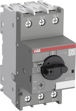
AL12-30-10 220V DC Contactor

Ordering
1 piece
85362010
Popular Downloads
Dimensions
45 mm
97.8 mm
86.05 mm
0.31 kg
Technical
(230 V AC) 100 kA
(400 V AC) 100 kA
(440 V AC) 30 kA
(230 V AC) 100 kA
(400 V AC) 100 kA
(440 V AC) 30 kA
(400 V AC) 100 kA
320 A
10 ... 16 A
Main Circuit 690 V AC
16 A
Main Circuit 50 Hz
Main Circuit 60 Hz
Main Circuit 50 Hz
Main Circuit 60 Hz
0 ... 400 Hz
Main Circuit 6 kV
690 V
at Rated Operating Conditions per Pole 0.9 ... 2.3 W
3P
Main Circuit 16 A
Housing IP20
Main Circuit Terminals IP10
Housing IP20
Main Circuit Terminals IP10
3
50000 cycle
Nr. Operations 100000 cycle
Screw Terminals
Flexible with Ferrule 1/2x 0.75 ... 6 mm²
Flexible with Insulated Ferrule 1/2x 0.75 ... 6 mm²
Flexible 1/2x 1 ... 2.5 mm²
Flexible 1/2x 2.5 ... 6 mm²
Rigid 1/2x 1 ... 2.5 mm²
Rigid 1/2x 2.5 ... 6 mm²
Flexible with Ferrule 1/2x 0.75 ... 6 mm²
Flexible with Insulated Ferrule 1/2x 0.75 ... 6 mm²
Flexible 1/2x 1 ... 2.5 mm²
Flexible 1/2x 2.5 ... 6 mm²
Rigid 1/2x 1 ... 2.5 mm²
Rigid 1/2x 2.5 ... 6 mm²
Main Circuit 2 N·m
Main Circuit 10 mm
M4
Pozidriv 2
M4
Pozidriv 2
1 ... 6
TH35-15 (35 x 15 mm Mounting Rail) acc. to IEC 60715
TH35-7.5 (35 x 7.5 mm Mounting Rail) acc. to IEC 60715
TH35-15 (35 x 15 mm Mounting Rail) acc. to IEC 60715
TH35-7.5 (35 x 7.5 mm Mounting Rail) acc. to IEC 60715
Electrical Conductive Board, Vertical 75 mm
Other Device Same Type, Horizontal 9 mm
Other Device Same Type, Vertical 150 mm
Electrical Conductive Board, Vertical 75 mm
Other Device Same Type, Horizontal 9 mm
Other Device Same Type, Vertical 150 mm
Rotary Handle
ON / OFF / TRIP
IEC/EN 60947-1
IEC/EN 60947-2
IEC/EN 60947-4-1
IEC 60335-2-40 A2L
IEC/EN 60947-1
IEC/EN 60947-2
IEC/EN 60947-4-1
IEC 60335-2-40 A2L
Technical UL/CSA
Any UL Listed Fuses or Circuit-Breakers, Tap Conductor Protection in Group Installations (480Y / 277 V AC) 30 kA
Any UL Listed Fuses or Circuit-Breakers, Tap Conductor Protection in Group Installations (600Y / 347 V AC) 18 kA
Any UL Listed Fuses or Circuit-Breakers, Tap Conductor Protection in Group Installations (480Y / 277 V AC) 30 kA
Any UL Listed Fuses or Circuit-Breakers, Tap Conductor Protection in Group Installations (600Y / 347 V AC) 18 kA
Main Circuit 600 V AC
(120 V AC) Single Phase 1 Hp
(220 ... 240 V AC) Single Phase 2 Hp
(120 V AC) Single Phase 1 Hp
(220 ... 240 V AC) Single Phase 2 Hp
(120 V AC) Single Phase 16 A
(220 ... 240 V AC) Single Phase 12 A
(120 V AC) Single Phase 16 A
(220 ... 240 V AC) Single Phase 12 A
(120 V AC) Single Phase 96 A
(220 ... 240 V AC) Single Phase 96 A
(120 V AC) Single Phase 96 A
(220 ... 240 V AC) Single Phase 96 A
Flexible 1/2x 16-8 AWG
Stranded 1/2x 16-8 AWG
Flexible 1/2x 16-8 AWG
Stranded 1/2x 16-8 AWG
Main Circuit 16 in·lb
Environmental
Around the Enclosure 0 ... +40 °C
Operation -25 ... +70 °C
Operation Compensated -25 ... +60 °C
Storage -50 ... +80 °C
Around the Enclosure 0 ... +40 °C
Operation -25 ... +70 °C
Operation Compensated -25 ... +60 °C
Storage -50 ... +80 °C
Yes
2000 m
11 ms Pulse 25g
5g 3 ... 150 Hz
Material Compliance
Following EU Directive 2011/65/EU and Amendment 2015/863 July 22, 2019
Business To Business
5. Small Equipment (No External Dimension More Than 50 cm)
ABB EcoSolutions
Certificates and Declarations
Container Information
box 1 piece
92 mm
102 mm
50 mm
0.325 kg
4013614485022
carton 40 piece
280 mm
395 mm
210 mm
13.386 kg
4013614487224
External Classifications and Standards
F
EC000228 - Power circuit-breaker for trafo/generator/installation protection
EC000228 - Power circuit-breaker for trafo/generator/installation protection
V11.0 : 27370409
39121601
4864 >> Enclosed 3 Pole Circuit Breakers
3707273
4364110
Ordering
1 piece
85362010
Popular Downloads
Dimensions
45 mm
97.8 mm
85.4 mm
0.31 kg
Technical
(230 V AC) 10 kA
(400 V AC) 10 kA
(440 V AC) 3 kA
(500 V AC) 3 kA
(690 V AC) 2 kA
(230 V AC) 10 kA
(400 V AC) 10 kA
(440 V AC) 3 kA
(500 V AC) 3 kA
(690 V AC) 2 kA
(230 V AC) 16 kA
(400 V AC) 16 kA
(440 V AC) 15 kA
(500 V AC) 10 kA
(690 V AC) 3 kA
(230 V AC) 16 kA
(400 V AC) 16 kA
(440 V AC) 15 kA
(500 V AC) 10 kA
(690 V AC) 3 kA
375 A
20 ... 25 A
(400 V) Three Phase 11 kW
(400 V) Three Phase 11 kW
Main Circuit 690 V AC
25 A
25 A
25 A
Main Circuit 50 Hz
Main Circuit 60 Hz
Main Circuit 50 Hz
Main Circuit 60 Hz
Main Circuit 6 kV
690 V
at Rated Operating Conditions per Pole 1.8 ... 2.8 W
3P
Main Circuit 25 A
Housing IP20
Main Circuit Terminals IP10
Housing IP20
Main Circuit Terminals IP10
3
50000 cycle
Nr. Operations 100000 cycle
Screw Terminals
Flexible with Ferrule 1/2x 0.75 ... 6 mm²
Flexible with Insulated Ferrule 1/2x 0.75 ... 6 mm²
Flexible 1/2x 1 ... 2.5 mm²
Flexible 1/2x 2.5 ... 6 mm²
Rigid 1/2x 1 ... 2.5 mm²
Rigid 1/2x 2.5 ... 6 mm²
Flexible with Ferrule 1/2x 0.75 ... 6 mm²
Flexible with Insulated Ferrule 1/2x 0.75 ... 6 mm²
Flexible 1/2x 1 ... 2.5 mm²
Flexible 1/2x 2.5 ... 6 mm²
Rigid 1/2x 1 ... 2.5 mm²
Rigid 1/2x 2.5 ... 6 mm²
Main Circuit 2 N·m
Main Circuit 10 mm
Pozidriv 2
1 ... 6
TH35-15 (35 x 15 mm Mounting Rail) acc. to IEC 60715
TH35-7.5 (35 x 7.5 mm Mounting Rail) acc. to IEC 60715
TH35-15 (35 x 15 mm Mounting Rail) acc. to IEC 60715
TH35-7.5 (35 x 7.5 mm Mounting Rail) acc. to IEC 60715
Electrical Conductive Board, Horizontal - Up to 400 V 0 mm
Electrical Conductive Board, Horizontal - Up to 690 V 1.5 mm
Electrical Conductive Board, Vertical 75 mm
Other Device Same Type, Horizontal 0 mm
Other Device Same Type, Vertical 150 mm
Electrical Conductive Board, Horizontal - Up to 400 V 0 mm
Electrical Conductive Board, Horizontal - Up to 690 V 1.5 mm
Electrical Conductive Board, Vertical 75 mm
Other Device Same Type, Horizontal 0 mm
Other Device Same Type, Vertical 150 mm
Rotary Handle
ON / OFF
IEC/EN 60947-1
IEC/EN 60947-2
IEC/EN 60947-4-1
UL 60947-1
UL 60947-4-1
IEC 60335-2-40 A2L
IEC/EN 60947-1
IEC/EN 60947-2
IEC/EN 60947-4-1
UL 60947-1
UL 60947-4-1
IEC 60335-2-40 A2L
Technical UL/CSA
Any UL Listed Fuses or Circuit-Breakers, Group Installations (480 V AC) 18 kA
Any UL Listed Fuses or Circuit-Breakers, Group Installations (600 V AC) 5 kA
Any UL Listed Fuses or Circuit-Breakers, Motor Disconnect (480 V AC) 18 kA
Any UL Listed Fuses or Circuit-Breakers, Motor Disconnect (600 V AC) 5 kA
Any UL Listed Fuses or Circuit-Breakers, Group Installations (480 V AC) 18 kA
Any UL Listed Fuses or Circuit-Breakers, Group Installations (600 V AC) 5 kA
Any UL Listed Fuses or Circuit-Breakers, Motor Disconnect (480 V AC) 18 kA
Any UL Listed Fuses or Circuit-Breakers, Motor Disconnect (600 V AC) 5 kA
Main Circuit 600 V AC
(200 V AC) Three Phase 5 Hp
(208 V AC) Three Phase 7.5 Hp
(220 ... 240 V AC) Three Phase 7.5 Hp
(440 ... 480 V AC) Three Phase 15 Hp
(550 ... 600 V AC) Three Phase 20 Hp
(200 V AC) Three Phase 5 Hp
(208 V AC) Three Phase 7.5 Hp
(220 ... 240 V AC) Three Phase 7.5 Hp
(440 ... 480 V AC) Three Phase 15 Hp
(550 ... 600 V AC) Three Phase 20 Hp
(200 V AC) Three Phase 17.5 A
(208 V AC) Three Phase 24.2 A
(220 ... 240 V AC) Three Phase 22 A
(440 ... 480 V AC) Three Phase 21 A
(550 ... 600 V AC) Three Phase 22 A
(200 V AC) Three Phase 17.5 A
(208 V AC) Three Phase 24.2 A
(220 ... 240 V AC) Three Phase 22 A
(440 ... 480 V AC) Three Phase 21 A
(550 ... 600 V AC) Three Phase 22 A
(200 V AC) Three Phase 105.8 A
(208 V AC) Three Phase 140 A
(220 ... 240 V AC) Three Phase 127 A
(440 ... 480 V AC) Three Phase 116 A
(550 ... 600 V AC) Three Phase 116 A
(200 V AC) Three Phase 105.8 A
(208 V AC) Three Phase 140 A
(220 ... 240 V AC) Three Phase 127 A
(440 ... 480 V AC) Three Phase 116 A
(550 ... 600 V AC) Three Phase 116 A
(600 V AC) 25 A
Flexible 1/2x 16-8 AWG
Stranded 1/2x 16-8 AWG
Flexible 1/2x 16-8 AWG
Stranded 1/2x 16-8 AWG
Main Circuit 18 in·lb
Environmental
Around the Enclosure 0 ... +40 °C
Operation -25 ... +70 °C
Operation Compensated -25 ... +55 °C
Storage -50 ... +80 °C
Around the Enclosure 0 ... +40 °C
Operation -25 ... +70 °C
Operation Compensated -25 ... +55 °C
Storage -50 ... +80 °C
Yes
2000 m
11 ms Pulse 25g
2g 5 ... 150 Hz
5g 3 ... 150 Hz
2g 5 ... 150 Hz
5g 3 ... 150 Hz
Material Compliance
Following EU Directive 2011/65/EU and Amendment 2015/863 July 22, 2019
Business To Business
5. Small Equipment (No External Dimension More Than 50 cm)
ABB EcoSolutions
Certificates and Declarations
Container Information
box 1 piece
92 mm
102 mm
50 mm
0.325 kg
4013614405662
carton 40 piece
280 mm
395 mm
210 mm
13.386 kg
4013614408748
External Classifications and Standards
F
EC000074 - Motor protection circuit-breaker
EC000074 - Motor protection circuit-breaker
V11.0 : 27370401
39121521
4731 >> Manual Starters
3705874
4364487
3111952

Ordering
1 piece
85364900
Popular Downloads
Dimensions
45 mm
77 mm
86 mm
0.31 kg
Technical
3
0
0
1
3P
IEC/EN 60947-1, IEC/EN 60947-4-1, UL 60335-2-40 LZGH2 A2L, UL 60947-4-1, CSA C22.2 No. 60335-2-40 LZGH2 A2L, CSA C22.2 No. 60947-4-1
Auxiliary Circuit 690 V
Main Circuit 690 V
Auxiliary Circuit 690 V
Main Circuit 690 V
Auxiliary Circuit 50 / 60 Hz
Control Circuit 50 / 60 Hz
Main Circuit 50 / 60 Hz
Auxiliary Circuit 50 / 60 Hz
Control Circuit 50 / 60 Hz
Main Circuit 50 / 60 Hz
acc. to IEC 60947-4-1, Open Contactors Θ = 40 °C 35 A
acc. to IEC 60947-5-1, Θ = 40 °C 16 A
acc. to IEC 60947-4-1, Open Contactors Θ = 40 °C 35 A
acc. to IEC 60947-5-1, Θ = 40 °C 16 A
(690 V) 40 °C 30 A
(690 V) 60 °C 30 A
(690 V) 70 °C 26 A
(690 V) 40 °C 30 A
(690 V) 60 °C 30 A
(690 V) 70 °C 26 A
(415 V) 60 °C 18 A
(440 V) 60 °C 18 A
(500 V) 60 °C 15 A
(690 V) 60 °C 10.5 A
(380 / 400 V) 60 °C 18 A
(220 / 230 / 240 V) 60 °C 18 A
(415 V) 60 °C 18 A
(440 V) 60 °C 18 A
(500 V) 60 °C 15 A
(690 V) 60 °C 10.5 A
(380 / 400 V) 60 °C 18 A
(220 / 230 / 240 V) 60 °C 18 A
(415 V) 60 °C 18 A
(440 V) 60 °C 18 A
(500 V) 60 °C 15 A
(690 V) 60 °C 10.5 A
(380 / 400 V) 60 °C 18 A
(220 / 230 / 240 V) 60 °C 18 A
(415 V) 60 °C 18 A
(440 V) 60 °C 18 A
(500 V) 60 °C 15 A
(690 V) 60 °C 10.5 A
(380 / 400 V) 60 °C 18 A
(220 / 230 / 240 V) 60 °C 18 A
(500 V) 2 A
(690 V) 2 A
(24 / 127 V) 6 A
(220 / 240 V) 4 A
(400 / 440 V) 3 A
(500 V) 2 A
(690 V) 2 A
(24 / 127 V) 6 A
(220 / 240 V) 4 A
(400 / 440 V) 3 A
(110 V) 1-Pole, 40 °C 20 A
(110 V) 1-Pole, 60 °C 20 A
(110 V) 1-Pole, 70 °C 20 A
(110 V) 2 Poles in Series, 40 °C 30 A
(110 V) 2 Poles in Series, 60 °C 30 A
(110 V) 2 Poles in Series, 70 °C 26 A
(110 V) 3 Poles in Series, 40 °C 30 A
(110 V) 3 Poles in Series, 60 °C 30 A
(110 V) 3 Poles in Series, 70 °C 26 A
(220 V) 2 Poles in Series, 40 °C 20 A
(220 V) 2 Poles in Series, 60 °C 20 A
(220 V) 2 Poles in Series, 70 °C 20 A
(220 V) 3 Poles in Series, 40 °C 30 A
(220 V) 3 Poles in Series, 60 °C 30 A
(220 V) 3 Poles in Series, 70 °C 26 A
(72 V) 1-Pole, 40 °C 30 A
(72 V) 1-Pole, 60 °C 30 A
(72 V) 1-Pole, 70 °C 26 A
(72 V) 2 Poles in Series, 40 °C 30 A
(72 V) 2 Poles in Series, 60 °C 30 A
(72 V) 2 Poles in Series, 70 °C 26 A
(72 V) 3 Poles in Series, 40 °C 30 A
(72 V) 3 Poles in Series, 60 °C 30 A
(72 V) 3 Poles in Series, 70 °C 26 A
(110 V) 1-Pole, 40 °C 20 A
(110 V) 1-Pole, 60 °C 20 A
(110 V) 1-Pole, 70 °C 20 A
(110 V) 2 Poles in Series, 40 °C 30 A
(110 V) 2 Poles in Series, 60 °C 30 A
(110 V) 2 Poles in Series, 70 °C 26 A
(110 V) 3 Poles in Series, 40 °C 30 A
(110 V) 3 Poles in Series, 60 °C 30 A
(110 V) 3 Poles in Series, 70 °C 26 A
(220 V) 2 Poles in Series, 40 °C 20 A
(110 V) 1-Pole, 40 °C 8 A
(110 V) 1-Pole, 60 °C 8 A
(110 V) 1-Pole, 70 °C 8 A
(110 V) 2 Poles in Series, 40 °C 30 A
(110 V) 2 Poles in Series, 60 °C 30 A
(110 V) 2 Poles in Series, 70 °C 26 A
(110 V) 3 Poles in Series, 40 °C 30 A
(110 V) 3 Poles in Series, 60 °C 30 A
(110 V) 3 Poles in Series, 70 °C 26 A
(220 V) 2 Poles in Series, 40 °C 8 A
(220 V) 2 Poles in Series, 60 °C 8 A
(220 V) 2 Poles in Series, 70 °C 8 A
(220 V) 3 Poles in Series, 40 °C 30 A
(220 V) 3 Poles in Series, 60 °C 30 A
(220 V) 3 Poles in Series, 70 °C 26 A
(72 V) 1-Pole, 40 °C 30 A
(72 V) 1-Pole, 60 °C 30 A
(72 V) 1-Pole, 70 °C 26 A
(72 V) 2 Poles in Series, 40 °C 30 A
(72 V) 2 Poles in Series, 60 °C 30 A
(72 V) 2 Poles in Series, 70 °C 26 A
(72 V) 3 Poles in Series, 40 °C 30 A
(72 V) 3 Poles in Series, 60 °C 30 A
(72 V) 3 Poles in Series, 70 °C 26 A
(110 V) 1-Pole, 40 °C 8 A
(110 V) 1-Pole, 60 °C 8 A
(110 V) 1-Pole, 70 °C 8 A
(110 V) 2 Poles in Series, 40 °C 30 A
(110 V) 2 Poles in Series, 60 °C 30 A
(110 V) 2 Poles in Series, 70 °C 26 A
(110 V) 3 Poles in Series, 40 °C 30 A
(110 V) 3 Poles in Series, 60 °C 30 A
(110 V) 3 Poles in Series, 70 °C 26 A
(220 V) 2 Poles in Series, 40 °C 8 A
(110 V) 1-Pole, 40 °C 4 A
(110 V) 1-Pole, 60 °C 4 A
(110 V) 1-Pole, 70 °C 4 A
(110 V) 2 Poles in Series, 40 °C 20 A
(110 V) 2 Poles in Series, 60 °C 20 A
(110 V) 2 Poles in Series, 70 °C 20 A
(110 V) 3 Poles in Series, 40 °C 30 A
(110 V) 3 Poles in Series, 60 °C 30 A
(110 V) 3 Poles in Series, 70 °C 26 A
(220 V) 2 Poles in Series, 40 °C 4 A
(220 V) 2 Poles in Series, 60 °C 4 A
(220 V) 2 Poles in Series, 70 °C 4 A
(220 V) 3 Poles in Series, 40 °C 16 A
(220 V) 3 Poles in Series, 60 °C 16 A
(220 V) 3 Poles in Series, 70 °C 16 A
(72 V) 1-Pole, 40 °C 16 A
(72 V) 1-Pole, 60 °C 16 A
(72 V) 1-Pole, 70 °C 16 A
(72 V) 2 Poles in Series, 40 °C 30 A
(72 V) 2 Poles in Series, 60 °C 30 A
(72 V) 2 Poles in Series, 70 °C 26 A
(72 V) 3 Poles in Series, 40 °C 30 A
(72 V) 3 Poles in Series, 60 °C 30 A
(72 V) 3 Poles in Series, 70 °C 26 A
(110 V) 1-Pole, 40 °C 4 A
(110 V) 1-Pole, 60 °C 4 A
(110 V) 1-Pole, 70 °C 4 A
(110 V) 2 Poles in Series, 40 °C 20 A
(110 V) 2 Poles in Series, 60 °C 20 A
(110 V) 2 Poles in Series, 70 °C 20 A
(110 V) 3 Poles in Series, 40 °C 30 A
(110 V) 3 Poles in Series, 60 °C 30 A
(110 V) 3 Poles in Series, 70 °C 26 A
(220 V) 2 Poles in Series, 40 °C 4 A
(24 V) 6 A / 144 W
(48 V) 2.8 A / 134 W
(72 V) 1 A / 72 W
(110 V) 0.55 A / 60 W
(125 V) 0.55 A / 69 W
(220 V) 0.27 A / 60 W
(250 V) 0.27 A / 68 W
(400 V) 0.15 A / 60 W
(500 V) 0.13 A / 65 W
(600 V) 0.1 A / 60 W
(24 V) 6 A / 144 W
(48 V) 2.8 A / 134 W
(72 V) 1 A / 72 W
(110 V) 0.55 A / 60 W
(125 V) 0.55 A / 69 W
(220 V) 0.27 A / 60 W
(250 V) 0.27 A / 68 W
(400 V) 0.15 A / 60 W
(500 V) 0.13 A / 65 W
(600 V) 0.1 A / 60 W
(400 V) 7.5 kW
(415 V) 9 kW
(440 V) 9 kW
(500 V) 9 kW
(690 V) 9 kW
(380 / 400 V) 7.5 kW
(220 / 230 / 240 V) 4 kW
(400 V) 7.5 kW
(415 V) 9 kW
(440 V) 9 kW
(500 V) 9 kW
(690 V) 9 kW
(380 / 400 V) 7.5 kW
(220 / 230 / 240 V) 4 kW
(415 V) 9 kW
(440 V) 9 kW
(500 V) 9 kW
(690 V) 9 kW
(380 / 400 V) 7.5 kW
(220 / 230 / 240 V) 4 kW
(415 V) 9 kW
(440 V) 9 kW
(500 V) 9 kW
(690 V) 9 kW
(380 / 400 V) 7.5 kW
(220 / 230 / 240 V) 4 kW
at 40 °C Ambient Temp, in Free Air, from a Cold State 10 s 150 A
at 40 °C Ambient Temp, in Free Air, from a Cold State 15 min 35 A
at 40 °C Ambient Temp, in Free Air, from a Cold State 1 min 60 A
at 40 °C Ambient Temp, in Free Air, from a Cold State 1 s 300 A
at 40 °C Ambient Temp, in Free Air, from a Cold State 30 s 80 A
for 0.1 s 140 A
for 1 s 100 A
cos phi=0.45 (cos phi=0.35 for Ie > 100 A) at 440 V 250 A
cos phi=0.45 (cos phi=0.35 for Ie > 100 A) at 690 V 106 A
cos phi=0.45 (cos phi=0.35 for Ie > 100 A) at 440 V 250 A
cos phi=0.45 (cos phi=0.35 for Ie > 100 A) at 690 V 106 A
acc. to IEC 60947-4-1 690 V
acc. to IEC 60947-5-1 690 V
acc. to UL/CSA 600 V
acc. to IEC 60947-4-1 690 V
acc. to IEC 60947-5-1 690 V
acc. to UL/CSA 600 V
6 kV
(AC-1) 600 cycles per hour
(AC-15) 1200 cycles per hour
(AC-2 / AC-4) 300 cycles per hour
(AC-3) 1200 cycles per hour
(DC-13) 900 cycles per hour
(AC-1) 600 cycles per hour
(AC-15) 1200 cycles per hour
(AC-2 / AC-4) 300 cycles per hour
(AC-3) 1200 cycles per hour
(DC-13) 900 cycles per hour
3600 cycles per hour
50 Hz 24 ... 60 V
60 Hz 24 ... 60 V
DC Operation 20 ... 60 V
50 Hz 24 ... 60 V
60 Hz 24 ... 60 V
DC Operation 20 ... 60 V
at 6 A per Pole 0.1 W
at Rated Operating Conditions AC-1 per Pole 1.2 W
at Rated Operating Conditions AC-3 per Pole 0.35 W
at 6 A per Pole 0.1 W
at Rated Operating Conditions AC-1 per Pole 1.2 W
at Rated Operating Conditions AC-3 per Pole 0.35 W
Between Coil De-energization and NC Contact Closing 13 ... 98 ms
Between Coil De-energization and NO Contact Opening 11 ... 95 ms
Between Coil Energization and NC Contact Opening 38 ... 90 ms
Between Coil Energization and NO Contact Closing 40 ... 95 ms
Between Coil De-energization and NC Contact Closing 13 ... 98 ms
Between Coil De-energization and NO Contact Opening 11 ... 95 ms
Between Coil Energization and NC Contact Opening 38 ... 90 ms
Between Coil Energization and NO Contact Closing 40 ... 95 ms
TH35-15 (35 x 15 mm Mounting Rail) acc. to IEC 60715
TH35-7.5 (35 x 7.5 mm Mounting Rail) acc. to IEC 60715
TH35-15 (35 x 15 mm Mounting Rail) acc. to IEC 60715
TH35-7.5 (35 x 7.5 mm Mounting Rail) acc. to IEC 60715
2 x M4 Screws Placed Diagonally
Flexible with Ferrule 1/2x 0.75 ... 6 mm²
Flexible with Insulated Ferrule 1x 0.75 ... 4 mm²
Flexible with Insulated Ferrule 2x 0.75 ... 2.5 mm²
Rigid Solid 1/2x 1 ... 4 mm²
Rigid Stranded 1/2x 1 ... 6 mm²
Flexible with Ferrule 1/2x 0.75 ... 6 mm²
Flexible with Insulated Ferrule 1x 0.75 ... 4 mm²
Flexible with Insulated Ferrule 2x 0.75 ... 2.5 mm²
Rigid Solid 1/2x 1 ... 4 mm²
Rigid Stranded 1/2x 1 ... 6 mm²
Flexible with Ferrule 1/2x 0.75 ... 2.5 mm²
Flexible with Insulated Ferrule 2x 0.75 ... 1.5 mm²
Flexible with Insulated Ferrule 1x 0.75 ... 2.5 mm²
Rigid Solid 1/2x 1 ... 2.5 mm²
Rigid Stranded 1/2x 1 ... 2.5 mm²
Flexible with Ferrule 1/2x 0.75 ... 2.5 mm²
Flexible with Insulated Ferrule 2x 0.75 ... 1.5 mm²
Flexible with Insulated Ferrule 1x 0.75 ... 2.5 mm²
Rigid Solid 1/2x 1 ... 2.5 mm²
Rigid Stranded 1/2x 1 ... 2.5 mm²
Flexible with Ferrule 1/2x 0.75 ... 2.5 mm²
Flexible with Insulated Ferrule 1x 0.75 ... 2.5 mm²
Flexible with Insulated Ferrule 2x 0.75 ... 1.5 mm²
Rigid Solid 1/2x 1 ... 2.5 mm²
Rigid Stranded 1/2x 1 ... 2.5 mm²
Flexible with Ferrule 1/2x 0.75 ... 2.5 mm²
Flexible with Insulated Ferrule 1x 0.75 ... 2.5 mm²
Flexible with Insulated Ferrule 2x 0.75 ... 1.5 mm²
Rigid Solid 1/2x 1 ... 2.5 mm²
Rigid Stranded 1/2x 1 ... 2.5 mm²
Auxiliary Circuit 10 mm
Control Circuit 10 mm
Main Circuit 10 mm
Auxiliary Circuit 10 mm
Control Circuit 10 mm
Main Circuit 10 mm
acc. to IEC 60529, IEC 60947-1, EN 60529 Auxiliary Terminals IP20
acc. to IEC 60529, IEC 60947-1, EN 60529 Coil Terminals IP20
acc. to IEC 60529, IEC 60947-1, EN 60529 Main Terminals IP20
acc. to IEC 60529, IEC 60947-1, EN 60529 Auxiliary Terminals IP20
acc. to IEC 60529, IEC 60947-1, EN 60529 Coil Terminals IP20
acc. to IEC 60529, IEC 60947-1, EN 60529 Main Terminals IP20
Auxiliary Circuit 1.2 N·m
Control Circuit 1.2 N·m
Main Circuit 1.5 N·m
Auxiliary Circuit 1.2 N·m
Control Circuit 1.2 N·m
Main Circuit 1.5 N·m
Screw Terminals
Block Contactor
Technical UL/CSA
Main Circuit 600 V
(600 V AC) 30 A
(120 V AC) Single Phase 1-1/2 hp
(200 ... 208 V AC) Three Phase 5 hp
(220 ... 240 V AC) Three Phase 5 hp
(240 V AC) Single Phase 3 hp
(440 ... 480 V AC) Three Phase 10 hp
(550 ... 600 V AC) Three Phase 15 hp
(120 V AC) Single Phase 1-1/2 hp
(200 ... 208 V AC) Three Phase 5 hp
(220 ... 240 V AC) Three Phase 5 hp
(240 V AC) Single Phase 3 hp
(440 ... 480 V AC) Three Phase 10 hp
(550 ... 600 V AC) Three Phase 15 hp
Rigid Solid 1/2x 16-10 AWG
Rigid Stranded 1/2x 16-10 AWG
Rigid Solid 1/2x 16-10 AWG
Rigid Stranded 1/2x 16-10 AWG
Rigid Solid 1/2x 18-14 AWG
Rigid Stranded 1/2x 18-14 AWG
Rigid Solid 1/2x 18-14 AWG
Rigid Stranded 1/2x 18-14 AWG
Rigid Solid 1/2x 18-14 AWG
Rigid Stranded 1/2x 18-14 AWG
Rigid Solid 1/2x 18-14 AWG
Rigid Stranded 1/2x 18-14 AWG
Auxiliary Circuit 11 in·lb
Control Circuit 11 in·lb
Main Circuit 13 in·lb
Auxiliary Circuit 11 in·lb
Control Circuit 11 in·lb
Main Circuit 13 in·lb
(120 V AC) Single Phase 20 A
(200 ... 208 V AC) Three Phase 17.5 A
(220 ... 240 V AC) Three Phase 15.2 A
(240 V AC) Single Phase 17 A
(440 ... 480 V AC) Three Phase 14 A
(550 ... 600 V AC) Three Phase 17 A
(120 V AC) Single Phase 20 A
(200 ... 208 V AC) Three Phase 17.5 A
(220 ... 240 V AC) Three Phase 15.2 A
(240 V AC) Single Phase 17 A
(440 ... 480 V AC) Three Phase 14 A
(550 ... 600 V AC) Three Phase 17 A
Environmental
Close to Contactor Fitted with Thermal O/L Relay -25 ... 60 °C
Close to Contactor without Thermal O/L Relay -40 ... 70 °C
Close to Contactor for Storage -60 ... +80 °C
Close to Contactor Fitted with Thermal O/L Relay -25 ... 60 °C
Close to Contactor without Thermal O/L Relay -40 ... 70 °C
Close to Contactor for Storage -60 ... +80 °C
Category B according to IEC 60947-1 Annex Q
Without Derating 3000 m
Closed, Shock Direction: B1 25 g
Open, Shock Direction: B1 5 g
Shock Direction: A 30 g
Shock Direction: B2 15 g
Shock Direction: C1 25 g
Shock Direction: C2 25 g
Closed, Shock Direction: B1 25 g
Open, Shock Direction: B1 5 g
Shock Direction: A 30 g
Shock Direction: B2 15 g
Shock Direction: C1 25 g
Shock Direction: C2 25 g
4g Closed Position & 2g Open position 5 ... 300 Hz
3
Material Compliance
Following EU Directive 2011/65/EU and Amendment 2015/863 July 22, 2019
a7d86a81-6ad0-4cac-bc5f-8b505d0eedfa China
Business To Business
5. Small Equipment (No External Dimension More Than 50 cm)
ABB EcoSolutions
Recycled Cardboard - 86 %
Recycled Metal - 28 %
Certificates and Declarations
Container Information
box 1 piece
87 mm
79 mm
47 mm
0.31 kg
3471523113916
box 27 piece
250 mm
300 mm
315 mm
8.37 kg
External Classifications and Standards
Q
EC000066 - Power contactor, AC switching
EC000066 - Power contactor, AC switching
EC000066 - Power contactor, AC switching
V11.0 : 27371003
39121529
4758 >> Iec Contactors
3706256
3211369
AF16Z-30-01K-20 COIL 12-20VDC

MS132-20T Switch for transformer protection MS13220T

Ordering
1 piece
85362010
Popular Downloads
Dimensions
45 mm
97.8 mm
85.4 mm
0.31 kg
Technical
(230 V AC) 10 kA
(400 V AC) 10 kA
(440 V AC) 3 kA
(500 V AC) 3 kA
(690 V AC) 2 kA
(230 V AC) 10 kA
(400 V AC) 10 kA
(440 V AC) 3 kA
(500 V AC) 3 kA
(690 V AC) 2 kA
(230 V AC) 16 kA
(400 V AC) 16 kA
(440 V AC) 15 kA
(500 V AC) 10 kA
(690 V AC) 3 kA
(230 V AC) 16 kA
(400 V AC) 16 kA
(440 V AC) 15 kA
(500 V AC) 10 kA
(690 V AC) 3 kA
480 A
25 ... 32 A
(400 V) Three Phase 15 kW
(400 V) Three Phase 15 kW
Main Circuit 690 V AC
32 A
32 A
32 A
Main Circuit 50 Hz
Main Circuit 60 Hz
Main Circuit 50 Hz
Main Circuit 60 Hz
Main Circuit 6 kV
690 V
at Rated Operating Conditions per Pole 1.9 ... 3.1 W
3P
Main Circuit 32 A
Housing IP20
Main Circuit Terminals IP10
Housing IP20
Main Circuit Terminals IP10
3
50000 cycle
Nr. Operations 100000 cycle
Screw Terminals
Flexible with Ferrule 1/2x 0.75 ... 6 mm²
Flexible with Insulated Ferrule 1/2x 0.75 ... 6 mm²
Flexible 1/2x 1 ... 2.5 mm²
Flexible 1/2x 2.5 ... 6 mm²
Rigid 1/2x 1 ... 2.5 mm²
Rigid 1/2x 2.5 ... 6 mm²
Flexible with Ferrule 1/2x 0.75 ... 6 mm²
Flexible with Insulated Ferrule 1/2x 0.75 ... 6 mm²
Flexible 1/2x 1 ... 2.5 mm²
Flexible 1/2x 2.5 ... 6 mm²
Rigid 1/2x 1 ... 2.5 mm²
Rigid 1/2x 2.5 ... 6 mm²
Main Circuit 2 N·m
Main Circuit 10 mm
Pozidriv 2
1 ... 6
TH35-15 (35 x 15 mm Mounting Rail) acc. to IEC 60715
TH35-7.5 (35 x 7.5 mm Mounting Rail) acc. to IEC 60715
TH35-15 (35 x 15 mm Mounting Rail) acc. to IEC 60715
TH35-7.5 (35 x 7.5 mm Mounting Rail) acc. to IEC 60715
Electrical Conductive Board, Horizontal - Up to 400 V 0 mm
Electrical Conductive Board, Horizontal - Up to 690 V 1.5 mm
Electrical Conductive Board, Vertical 75 mm
Other Device Same Type, Horizontal 0 mm
Other Device Same Type, Vertical 150 mm
Electrical Conductive Board, Horizontal - Up to 400 V 0 mm
Electrical Conductive Board, Horizontal - Up to 690 V 1.5 mm
Electrical Conductive Board, Vertical 75 mm
Other Device Same Type, Horizontal 0 mm
Other Device Same Type, Vertical 150 mm
Rotary Handle
ON / OFF
IEC/EN 60947-1
IEC/EN 60947-2
IEC/EN 60947-4-1
UL 60947-1
UL 60947-4-1
IEC 60335-2-40 A2L
IEC/EN 60947-1
IEC/EN 60947-2
IEC/EN 60947-4-1
UL 60947-1
UL 60947-4-1
IEC 60335-2-40 A2L
Technical UL/CSA
Any UL Listed Fuses or Circuit-Breakers, Group Installations (480 V AC) 18 kA
Any UL Listed Fuses or Circuit-Breakers, Group Installations (600 V AC) 5 kA
Any UL Listed Fuses or Circuit-Breakers, Motor Disconnect (480 V AC) 18 kA
Any UL Listed Fuses or Circuit-Breakers, Motor Disconnect (600 V AC) 5 kA
Any UL Listed Fuses or Circuit-Breakers, Group Installations (480 V AC) 18 kA
Any UL Listed Fuses or Circuit-Breakers, Group Installations (600 V AC) 5 kA
Any UL Listed Fuses or Circuit-Breakers, Motor Disconnect (480 V AC) 18 kA
Any UL Listed Fuses or Circuit-Breakers, Motor Disconnect (600 V AC) 5 kA
Main Circuit 600 V AC
(200 V AC) Three Phase 7.5 Hp
(208 V AC) Three Phase 10 Hp
(220 ... 240 V AC) Three Phase 10 Hp
(440 ... 480 V AC) Three Phase 20 Hp
(550 ... 600 V AC) Three Phase 25 Hp
(200 V AC) Three Phase 7.5 Hp
(208 V AC) Three Phase 10 Hp
(220 ... 240 V AC) Three Phase 10 Hp
(440 ... 480 V AC) Three Phase 20 Hp
(550 ... 600 V AC) Three Phase 25 Hp
(200 V AC) Three Phase 25.3 A
(208 V AC) Three Phase 30.8 A
(220 ... 240 V AC) Three Phase 28 A
(440 ... 480 V AC) Three Phase 27 A
(550 ... 600 V AC) Three Phase 27 A
(200 V AC) Three Phase 25.3 A
(208 V AC) Three Phase 30.8 A
(220 ... 240 V AC) Three Phase 28 A
(440 ... 480 V AC) Three Phase 27 A
(550 ... 600 V AC) Three Phase 27 A
(200 V AC) Three Phase 146 A
(208 V AC) Three Phase 179 A
(220 ... 240 V AC) Three Phase 162 A
(440 ... 480 V AC) Three Phase 145 A
(550 ... 600 V AC) Three Phase 146 A
(200 V AC) Three Phase 146 A
(208 V AC) Three Phase 179 A
(220 ... 240 V AC) Three Phase 162 A
(440 ... 480 V AC) Three Phase 145 A
(550 ... 600 V AC) Three Phase 146 A
(600 V AC) 32 A
Flexible 1/2x 16-8 AWG
Stranded 1/2x 16-8 AWG
Flexible 1/2x 16-8 AWG
Stranded 1/2x 16-8 AWG
Main Circuit 18 in·lb
Environmental
Around the Enclosure 0 ... +40 °C
Operation -25 ... +70 °C
Operation Compensated -25 ... +55 °C
Storage -50 ... +80 °C
Around the Enclosure 0 ... +40 °C
Operation -25 ... +70 °C
Operation Compensated -25 ... +55 °C
Storage -50 ... +80 °C
Yes
2000 m
11 ms Pulse 25g
2g 5 ... 150 Hz
5g 3 ... 150 Hz
2g 5 ... 150 Hz
5g 3 ... 150 Hz
Material Compliance
Following EU Directive 2011/65/EU and Amendment 2015/863 July 22, 2019
Business To Business
5. Small Equipment (No External Dimension More Than 50 cm)
ABB EcoSolutions
Certificates and Declarations
Container Information
box 1 piece
92 mm
102 mm
50 mm
0.325 kg
4013614405679
carton 40 piece
280 mm
395 mm
210 mm
13.386 kg
4013614408755
External Classifications and Standards
F
EC000074 - Motor protection circuit-breaker
EC000074 - Motor protection circuit-breaker
V11.0 : 27370401
39121521
4731 >> Manual Starters
3705875
4364488
3111953

Ordering
1 piece
85364900
Popular Downloads
Dimensions
45 mm
77 mm
86 mm
0.31 kg
Technical
3
0
0
1
3P
IEC/EN 60947-1, IEC/EN 60947-4-1, UL 60335-2-40 LZGH2 A2L, UL 60947-4-1, CSA C22.2 No. 60335-2-40 LZGH2 A2L, CSA C22.2 No. 60947-4-1
Auxiliary Circuit 690 V
Main Circuit 690 V
Auxiliary Circuit 690 V
Main Circuit 690 V
Auxiliary Circuit 50 / 60 Hz
Main Circuit 50 / 60 Hz
Auxiliary Circuit 50 / 60 Hz
Main Circuit 50 / 60 Hz
acc. to IEC 60947-4-1, Open Contactors Θ = 40 °C 35 A
acc. to IEC 60947-5-1, Θ = 40 °C 16 A
acc. to IEC 60947-4-1, Open Contactors Θ = 40 °C 35 A
acc. to IEC 60947-5-1, Θ = 40 °C 16 A
(690 V) 40 °C 30 A
(690 V) 60 °C 30 A
(690 V) 70 °C 26 A
(690 V) 40 °C 30 A
(690 V) 60 °C 30 A
(690 V) 70 °C 26 A
(415 V) 60 °C 18 A
(440 V) 60 °C 18 A
(500 V) 60 °C 15 A
(690 V) 60 °C 10.5 A
(380 / 400 V) 60 °C 18 A
(220 / 230 / 240 V) 60 °C 18 A
(415 V) 60 °C 18 A
(440 V) 60 °C 18 A
(500 V) 60 °C 15 A
(690 V) 60 °C 10.5 A
(380 / 400 V) 60 °C 18 A
(220 / 230 / 240 V) 60 °C 18 A
(415 V) 60 °C 18 A
(440 V) 60 °C 18 A
(500 V) 60 °C 15 A
(690 V) 60 °C 10.5 A
(380 / 400 V) 60 °C 18 A
(220 / 230 / 240 V) 60 °C 18 A
(415 V) 60 °C 18 A
(440 V) 60 °C 18 A
(500 V) 60 °C 15 A
(690 V) 60 °C 10.5 A
(380 / 400 V) 60 °C 18 A
(220 / 230 / 240 V) 60 °C 18 A
(500 V) 2 A
(690 V) 2 A
(24 / 127 V) 6 A
(220 / 240 V) 4 A
(400 / 440 V) 3 A
(500 V) 2 A
(690 V) 2 A
(24 / 127 V) 6 A
(220 / 240 V) 4 A
(400 / 440 V) 3 A
(110 V) 1-Pole, 40 °C 20 A
(110 V) 1-Pole, 60 °C 20 A
(110 V) 1-Pole, 70 °C 20 A
(110 V) 2 Poles in Series, 40 °C 30 A
(110 V) 2 Poles in Series, 60 °C 30 A
(110 V) 2 Poles in Series, 70 °C 26 A
(110 V) 3 Poles in Series, 40 °C 30 A
(110 V) 3 Poles in Series, 60 °C 30 A
(110 V) 3 Poles in Series, 70 °C 26 A
(220 V) 2 Poles in Series, 40 °C 20 A
(220 V) 2 Poles in Series, 60 °C 20 A
(220 V) 2 Poles in Series, 70 °C 20 A
(220 V) 3 Poles in Series, 40 °C 30 A
(220 V) 3 Poles in Series, 60 °C 30 A
(220 V) 3 Poles in Series, 70 °C 26 A
(72 V) 1-Pole, 40 °C 30 A
(72 V) 1-Pole, 60 °C 30 A
(72 V) 1-Pole, 70 °C 26 A
(72 V) 2 Poles in Series, 40 °C 30 A
(72 V) 2 Poles in Series, 60 °C 30 A
(72 V) 2 Poles in Series, 70 °C 26 A
(72 V) 3 Poles in Series, 40 °C 30 A
(72 V) 3 Poles in Series, 60 °C 30 A
(72 V) 3 Poles in Series, 70 °C 26 A
(110 V) 1-Pole, 40 °C 20 A
(110 V) 1-Pole, 60 °C 20 A
(110 V) 1-Pole, 70 °C 20 A
(110 V) 2 Poles in Series, 40 °C 30 A
(110 V) 2 Poles in Series, 60 °C 30 A
(110 V) 2 Poles in Series, 70 °C 26 A
(110 V) 3 Poles in Series, 40 °C 30 A
(110 V) 3 Poles in Series, 60 °C 30 A
(110 V) 3 Poles in Series, 70 °C 26 A
(220 V) 2 Poles in Series, 40 °C 20 A
(110 V) 1-Pole, 40 °C 8 A
(110 V) 1-Pole, 60 °C 8 A
(110 V) 1-Pole, 70 °C 8 A
(110 V) 2 Poles in Series, 40 °C 30 A
(110 V) 2 Poles in Series, 60 °C 30 A
(110 V) 2 Poles in Series, 70 °C 26 A
(110 V) 3 Poles in Series, 40 °C 30 A
(110 V) 3 Poles in Series, 60 °C 30 A
(110 V) 3 Poles in Series, 70 °C 26 A
(220 V) 2 Poles in Series, 40 °C 8 A
(220 V) 2 Poles in Series, 60 °C 8 A
(220 V) 2 Poles in Series, 70 °C 8 A
(220 V) 3 Poles in Series, 40 °C 30 A
(220 V) 3 Poles in Series, 60 °C 30 A
(220 V) 3 Poles in Series, 70 °C 26 A
(72 V) 1-Pole, 40 °C 30 A
(72 V) 1-Pole, 60 °C 30 A
(72 V) 1-Pole, 70 °C 26 A
(72 V) 2 Poles in Series, 40 °C 30 A
(72 V) 2 Poles in Series, 60 °C 30 A
(72 V) 2 Poles in Series, 70 °C 26 A
(72 V) 3 Poles in Series, 40 °C 30 A
(72 V) 3 Poles in Series, 60 °C 30 A
(72 V) 3 Poles in Series, 70 °C 26 A
(110 V) 1-Pole, 40 °C 8 A
(110 V) 1-Pole, 60 °C 8 A
(110 V) 1-Pole, 70 °C 8 A
(110 V) 2 Poles in Series, 40 °C 30 A
(110 V) 2 Poles in Series, 60 °C 30 A
(110 V) 2 Poles in Series, 70 °C 26 A
(110 V) 3 Poles in Series, 40 °C 30 A
(110 V) 3 Poles in Series, 60 °C 30 A
(110 V) 3 Poles in Series, 70 °C 26 A
(220 V) 2 Poles in Series, 40 °C 8 A
(110 V) 1-Pole, 40 °C 4 A
(110 V) 1-Pole, 60 °C 4 A
(110 V) 1-Pole, 70 °C 4 A
(110 V) 2 Poles in Series, 40 °C 20 A
(110 V) 2 Poles in Series, 60 °C 20 A
(110 V) 2 Poles in Series, 70 °C 20 A
(110 V) 3 Poles in Series, 40 °C 30 A
(110 V) 3 Poles in Series, 60 °C 30 A
(110 V) 3 Poles in Series, 70 °C 26 A
(220 V) 2 Poles in Series, 40 °C 4 A
(220 V) 2 Poles in Series, 60 °C 4 A
(220 V) 2 Poles in Series, 70 °C 4 A
(220 V) 3 Poles in Series, 40 °C 16 A
(220 V) 3 Poles in Series, 60 °C 16 A
(220 V) 3 Poles in Series, 70 °C 16 A
(72 V) 1-Pole, 40 °C 16 A
(72 V) 1-Pole, 60 °C 16 A
(72 V) 1-Pole, 70 °C 16 A
(72 V) 2 Poles in Series, 40 °C 30 A
(72 V) 2 Poles in Series, 60 °C 30 A
(72 V) 2 Poles in Series, 70 °C 26 A
(72 V) 3 Poles in Series, 40 °C 30 A
(72 V) 3 Poles in Series, 60 °C 30 A
(72 V) 3 Poles in Series, 70 °C 26 A
(110 V) 1-Pole, 40 °C 4 A
(110 V) 1-Pole, 60 °C 4 A
(110 V) 1-Pole, 70 °C 4 A
(110 V) 2 Poles in Series, 40 °C 20 A
(110 V) 2 Poles in Series, 60 °C 20 A
(110 V) 2 Poles in Series, 70 °C 20 A
(110 V) 3 Poles in Series, 40 °C 30 A
(110 V) 3 Poles in Series, 60 °C 30 A
(110 V) 3 Poles in Series, 70 °C 26 A
(220 V) 2 Poles in Series, 40 °C 4 A
(24 V) 6 A / 144 W
(48 V) 2.8 A / 134 W
(72 V) 1 A / 72 W
(110 V) 0.55 A / 60 W
(125 V) 0.55 A / 69 W
(220 V) 0.27 A / 60 W
(250 V) 0.27 A / 68 W
(400 V) 0.15 A / 60 W
(500 V) 0.13 A / 65 W
(600 V) 0.1 A / 60 W
(24 V) 6 A / 144 W
(48 V) 2.8 A / 134 W
(72 V) 1 A / 72 W
(110 V) 0.55 A / 60 W
(125 V) 0.55 A / 69 W
(220 V) 0.27 A / 60 W
(250 V) 0.27 A / 68 W
(400 V) 0.15 A / 60 W
(500 V) 0.13 A / 65 W
(600 V) 0.1 A / 60 W
(400 V) 7.5 kW
(415 V) 9 kW
(440 V) 9 kW
(500 V) 9 kW
(690 V) 9 kW
(380 / 400 V) 7.5 kW
(220 / 230 / 240 V) 4 kW
(400 V) 7.5 kW
(415 V) 9 kW
(440 V) 9 kW
(500 V) 9 kW
(690 V) 9 kW
(380 / 400 V) 7.5 kW
(220 / 230 / 240 V) 4 kW
(415 V) 9 kW
(440 V) 9 kW
(500 V) 9 kW
(690 V) 9 kW
(380 / 400 V) 7.5 kW
(220 / 230 / 240 V) 4 kW
(415 V) 9 kW
(440 V) 9 kW
(500 V) 9 kW
(690 V) 9 kW
(380 / 400 V) 7.5 kW
(220 / 230 / 240 V) 4 kW
at 40 °C Ambient Temp, in Free Air, from a Cold State 10 s 150 A
at 40 °C Ambient Temp, in Free Air, from a Cold State 15 min 35 A
at 40 °C Ambient Temp, in Free Air, from a Cold State 1 min 60 A
at 40 °C Ambient Temp, in Free Air, from a Cold State 1 s 300 A
at 40 °C Ambient Temp, in Free Air, from a Cold State 30 s 80 A
for 0.1 s 140 A
for 1 s 100 A
at 40 °C Ambient Temp, in Free Air, from a Cold State 10 s 150 A
at 40 °C Ambient Temp, in Free Air, from a Cold State 15 min 35 A
at 40 °C Ambient Temp, in Free Air, from a Cold State 1 min 60 A
at 40 °C Ambient Temp, in Free Air, from a Cold State 1 s 300 A
at 40 °C Ambient Temp, in Free Air, from a Cold State 30 s 80 A
for 0.1 s 140 A
for 1 s 100 A
cos phi=0.45 (cos phi=0.35 for Ie > 100 A) at 440 V 250 A
cos phi=0.45 (cos phi=0.35 for Ie > 100 A) at 690 V 106 A
cos phi=0.45 (cos phi=0.35 for Ie > 100 A) at 440 V 250 A
cos phi=0.45 (cos phi=0.35 for Ie > 100 A) at 690 V 106 A
acc. to IEC 60947-4-1 690 V
acc. to IEC 60947-5-1 690 V
acc. to UL/CSA 600 V
acc. to IEC 60947-4-1 690 V
acc. to IEC 60947-5-1 690 V
acc. to UL/CSA 600 V
6 kV
(AC-1) 600 cycles per hour
(AC-15) 1200 cycles per hour
(AC-2 / AC-4) 300 cycles per hour
(AC-3) 1200 cycles per hour
(DC-13) 900 cycles per hour
(AC-1) 600 cycles per hour
(AC-15) 1200 cycles per hour
(AC-2 / AC-4) 300 cycles per hour
(AC-3) 1200 cycles per hour
(DC-13) 900 cycles per hour
3600 cycles per hour
DC Operation 12 ... 20 V
at 6 A per Pole 0.1 W
at Rated Operating Conditions AC-1 per Pole 1.2 W
at Rated Operating Conditions AC-3 per Pole 0.35 W
at 6 A per Pole 0.1 W
at Rated Operating Conditions AC-1 per Pole 1.2 W
at Rated Operating Conditions AC-3 per Pole 0.35 W
Between Coil De-energization and NC Contact Closing 13 ... 98 ms
Between Coil De-energization and NO Contact Opening 11 ... 95 ms
Between Coil Energization and NC Contact Opening 38 ... 90 ms
Between Coil Energization and NO Contact Closing 40 ... 95 ms
Between Coil De-energization and NC Contact Closing 13 ... 98 ms
Between Coil De-energization and NO Contact Opening 11 ... 95 ms
Between Coil Energization and NC Contact Opening 38 ... 90 ms
Between Coil Energization and NO Contact Closing 40 ... 95 ms
TH35-15 (35 x 15 mm Mounting Rail) acc. to IEC 60715
TH35-7.5 (35 x 7.5 mm Mounting Rail) acc. to IEC 60715
TH35-15 (35 x 15 mm Mounting Rail) acc. to IEC 60715
TH35-7.5 (35 x 7.5 mm Mounting Rail) acc. to IEC 60715
2 x M4 Screws Placed Diagonally
Flexible with Ferrule 1/2x 0.75 ... 6 mm²
Flexible with Insulated Ferrule 1x 0.75 ... 4 mm²
Flexible with Insulated Ferrule 2x 0.75 ... 2.5 mm²
Rigid Solid 1/2x 1 ... 4 mm²
Rigid Stranded 1/2x 1 ... 6 mm²
Flexible with Ferrule 1/2x 0.75 ... 6 mm²
Flexible with Insulated Ferrule 1x 0.75 ... 4 mm²
Flexible with Insulated Ferrule 2x 0.75 ... 2.5 mm²
Rigid Solid 1/2x 1 ... 4 mm²
Rigid Stranded 1/2x 1 ... 6 mm²
Flexible with Ferrule 1/2x 0.75 ... 2.5 mm²
Flexible with Insulated Ferrule 2x 0.75 ... 1.5 mm²
Flexible with Insulated Ferrule 1x 0.75 ... 2.5 mm²
Rigid Solid 1/2x 1 ... 2.5 mm²
Rigid Stranded 1/2x 1 ... 2.5 mm²
Flexible with Ferrule 1/2x 0.75 ... 2.5 mm²
Flexible with Insulated Ferrule 2x 0.75 ... 1.5 mm²
Flexible with Insulated Ferrule 1x 0.75 ... 2.5 mm²
Rigid Solid 1/2x 1 ... 2.5 mm²
Rigid Stranded 1/2x 1 ... 2.5 mm²
Flexible with Ferrule 1/2x 0.75 ... 2.5 mm²
Flexible with Insulated Ferrule 1x 0.75 ... 2.5 mm²
Flexible with Insulated Ferrule 2x 0.75 ... 1.5 mm²
Rigid Solid 1/2x 1 ... 2.5 mm²
Rigid Stranded 1/2x 1 ... 2.5 mm²
Flexible with Ferrule 1/2x 0.75 ... 2.5 mm²
Flexible with Insulated Ferrule 1x 0.75 ... 2.5 mm²
Flexible with Insulated Ferrule 2x 0.75 ... 1.5 mm²
Rigid Solid 1/2x 1 ... 2.5 mm²
Rigid Stranded 1/2x 1 ... 2.5 mm²
Auxiliary Circuit 10 mm
Control Circuit 10 mm
Main Circuit 10 mm
Auxiliary Circuit 10 mm
Control Circuit 10 mm
Main Circuit 10 mm
acc. to IEC 60529, IEC 60947-1, EN 60529 Auxiliary Terminals IP20
acc. to IEC 60529, IEC 60947-1, EN 60529 Coil Terminals IP20
acc. to IEC 60529, IEC 60947-1, EN 60529 Main Terminals IP20
acc. to IEC 60529, IEC 60947-1, EN 60529 Auxiliary Terminals IP20
acc. to IEC 60529, IEC 60947-1, EN 60529 Coil Terminals IP20
acc. to IEC 60529, IEC 60947-1, EN 60529 Main Terminals IP20
Auxiliary Circuit 1.2 N·m
Control Circuit 1.2 N·m
Main Circuit 1.5 N·m
Auxiliary Circuit 1.2 N·m
Control Circuit 1.2 N·m
Main Circuit 1.5 N·m
Screw Terminals
Block Contactor
Technical UL/CSA
Main Circuit 600 V
(600 V AC) 30 A
(120 V AC) Single Phase 1-1/2 hp
(200 ... 208 V AC) Three Phase 5 hp
(220 ... 240 V AC) Three Phase 5 hp
(240 V AC) Single Phase 3 hp
(440 ... 480 V AC) Three Phase 10 hp
(550 ... 600 V AC) Three Phase 15 hp
(120 V AC) Single Phase 1-1/2 hp
(200 ... 208 V AC) Three Phase 5 hp
(220 ... 240 V AC) Three Phase 5 hp
(240 V AC) Single Phase 3 hp
(440 ... 480 V AC) Three Phase 10 hp
(550 ... 600 V AC) Three Phase 15 hp
Rigid Solid 1/2x 16-10 AWG
Rigid Stranded 1/2x 16-10 AWG
Rigid Solid 1/2x 16-10 AWG
Rigid Stranded 1/2x 16-10 AWG
Rigid Solid 1/2x 18-14 AWG
Rigid Stranded 1/2x 18-14 AWG
Rigid Solid 1/2x 18-14 AWG
Rigid Stranded 1/2x 18-14 AWG
Rigid Solid 1/2x 18-14 AWG
Rigid Stranded 1/2x 18-14 AWG
Rigid Solid 1/2x 18-14 AWG
Rigid Stranded 1/2x 18-14 AWG
Auxiliary Circuit 11 in·lb
Control Circuit 11 in·lb
Main Circuit 13 in·lb
Auxiliary Circuit 11 in·lb
Control Circuit 11 in·lb
Main Circuit 13 in·lb
(120 V AC) Single Phase 20 A
(200 ... 208 V AC) Three Phase 17.5 A
(220 ... 240 V AC) Three Phase 15.2 A
(240 V AC) Single Phase 17 A
(440 ... 480 V AC) Three Phase 14 A
(550 ... 600 V AC) Three Phase 17 A
(120 V AC) Single Phase 20 A
(200 ... 208 V AC) Three Phase 17.5 A
(220 ... 240 V AC) Three Phase 15.2 A
(240 V AC) Single Phase 17 A
(440 ... 480 V AC) Three Phase 14 A
(550 ... 600 V AC) Three Phase 17 A
Environmental
Close to Contactor Fitted with Thermal O/L Relay -25 ... 60 °C
Close to Contactor without Thermal O/L Relay -40 ... 70 °C
Close to Contactor for Storage -60 ... +80 °C
Close to Contactor Fitted with Thermal O/L Relay -25 ... 60 °C
Close to Contactor without Thermal O/L Relay -40 ... 70 °C
Close to Contactor for Storage -60 ... +80 °C
Category B according to IEC 60947-1 Annex Q
Without Derating 3000 m
Closed, Shock Direction: B1 25 g
Open, Shock Direction: B1 5 g
Shock Direction: A 30 g
Shock Direction: B2 15 g
Shock Direction: C1 25 g
Shock Direction: C2 25 g
Closed, Shock Direction: B1 25 g
Open, Shock Direction: B1 5 g
Shock Direction: A 30 g
Shock Direction: B2 15 g
Shock Direction: C1 25 g
Shock Direction: C2 25 g
4g Closed Position & 2g Open position 5 ... 300 Hz
3
Material Compliance
Following EU Directive 2011/65/EU and Amendment 2015/863 July 22, 2019
Business To Business
5. Small Equipment (No External Dimension More Than 50 cm)
ABB EcoSolutions
Recycled Cardboard - 86 %
Recycled Metal - 28 %
Certificates and Declarations
Container Information
box 1 piece
87 mm
79 mm
47 mm
0.31 kg
3471523113909
box 27 piece
250 mm
300 mm
315 mm
8.37 kg
External Classifications and Standards
Q
EC000066 - Power contactor, AC switching
EC000066 - Power contactor, AC switching
EC000066 - Power contactor, AC switching
V11.0 : 27371003
39121529
4758 >> Iec Contactors
3706255

Ordering
1 piece
85362010
Popular Downloads
Dimensions
45 mm
97.8 mm
86.05 mm
0.31 kg
Technical
(230 V AC) 50 kA
(400 V AC) 50 kA
(440 V AC) 30 kA
(230 V AC) 50 kA
(400 V AC) 50 kA
(440 V AC) 30 kA
(400 V AC) 50 kA
500 A
20 ... 25 A
Main Circuit 690 V AC
25 A
Main Circuit 50 Hz
Main Circuit 60 Hz
Main Circuit 50 Hz
Main Circuit 60 Hz
0 ... 400 Hz
Main Circuit 6 kV
690 V
at Rated Operating Conditions per Pole 1.2 ... 1.9 W
3P
Main Circuit 25 A
Housing IP20
Main Circuit Terminals IP10
Housing IP20
Main Circuit Terminals IP10
3
50000 cycle
Nr. Operations 100000 cycle
Screw Terminals
Flexible with Ferrule 1/2x 0.75 ... 6 mm²
Flexible with Insulated Ferrule 1/2x 0.75 ... 6 mm²
Flexible 1/2x 1 ... 2.5 mm²
Flexible 1/2x 2.5 ... 6 mm²
Rigid 1/2x 1 ... 2.5 mm²
Rigid 1/2x 2.5 ... 6 mm²
Flexible with Ferrule 1/2x 0.75 ... 6 mm²
Flexible with Insulated Ferrule 1/2x 0.75 ... 6 mm²
Flexible 1/2x 1 ... 2.5 mm²
Flexible 1/2x 2.5 ... 6 mm²
Rigid 1/2x 1 ... 2.5 mm²
Rigid 1/2x 2.5 ... 6 mm²
Main Circuit 2 N·m
Main Circuit 10 mm
M4
Pozidriv 2
M4
Pozidriv 2
1 ... 6
TH35-15 (35 x 15 mm Mounting Rail) acc. to IEC 60715
TH35-7.5 (35 x 7.5 mm Mounting Rail) acc. to IEC 60715
TH35-15 (35 x 15 mm Mounting Rail) acc. to IEC 60715
TH35-7.5 (35 x 7.5 mm Mounting Rail) acc. to IEC 60715
Electrical Conductive Board, Vertical 75 mm
Other Device Same Type, Horizontal 9 mm
Other Device Same Type, Vertical 150 mm
Electrical Conductive Board, Vertical 75 mm
Other Device Same Type, Horizontal 9 mm
Other Device Same Type, Vertical 150 mm
Rotary Handle
ON / OFF / TRIP
IEC/EN 60947-1
IEC/EN 60947-2
IEC/EN 60947-4-1
IEC 60335-2-40 A2L
IEC/EN 60947-1
IEC/EN 60947-2
IEC/EN 60947-4-1
IEC 60335-2-40 A2L
Technical UL/CSA
Any UL Listed Fuses or Circuit-Breakers, Tap Conductor Protection in Group Installations (480Y / 277 V AC) 30 kA
Any UL Listed Fuses or Circuit-Breakers, Tap Conductor Protection in Group Installations (600Y / 347 V AC) 18 kA
Any UL Listed Fuses or Circuit-Breakers, Tap Conductor Protection in Group Installations (480Y / 277 V AC) 30 kA
Any UL Listed Fuses or Circuit-Breakers, Tap Conductor Protection in Group Installations (600Y / 347 V AC) 18 kA
Main Circuit 600 V AC
(120 V AC) Single Phase 2 Hp
(220 ... 240 V AC) Single Phase 3 Hp
(120 V AC) Single Phase 2 Hp
(220 ... 240 V AC) Single Phase 3 Hp
(120 V AC) Single Phase 24 A
(220 ... 240 V AC) Single Phase 17 A
(120 V AC) Single Phase 24 A
(220 ... 240 V AC) Single Phase 17 A
(120 V AC) Single Phase 144 A
(220 ... 240 V AC) Single Phase 144 A
(120 V AC) Single Phase 144 A
(220 ... 240 V AC) Single Phase 144 A
Flexible 1/2x 16-8 AWG
Stranded 1/2x 16-8 AWG
Flexible 1/2x 16-8 AWG
Stranded 1/2x 16-8 AWG
Main Circuit 16 in·lb
Environmental
Around the Enclosure 0 ... +40 °C
Operation -25 ... +70 °C
Operation Compensated -25 ... +60 °C
Storage -50 ... +80 °C
Around the Enclosure 0 ... +40 °C
Operation -25 ... +70 °C
Operation Compensated -25 ... +60 °C
Storage -50 ... +80 °C
Yes
2000 m
11 ms Pulse 25g
5g 3 ... 150 Hz
Material Compliance
Following EU Directive 2011/65/EU and Amendment 2015/863 July 22, 2019
Business To Business
5. Small Equipment (No External Dimension More Than 50 cm)
ABB EcoSolutions
Certificates and Declarations
Container Information
box 1 piece
92 mm
102 mm
50 mm
0.325 kg
4013614485046
carton 40 piece
280 mm
395 mm
210 mm
13.386 kg
4013614487248
External Classifications and Standards
F
EC000228 - Power circuit-breaker for trafo/generator/installation protection
EC000228 - Power circuit-breaker for trafo/generator/installation protection
V11.0 : 27370409
39121601
4864 >> Enclosed 3 Pole Circuit Breakers
3707276
4364113

Ordering
1 piece
85364900
Popular Downloads
Dimensions
45 mm
77 mm
86 mm
0.31 kg
Technical
4
0
0
0
4P
IEC/EN 60947-1, IEC/EN 60947-4-1, UL 60335-2-40 LZGH2 A2L, UL 60947-1, UL 60947-4-1, CSA C22.2 No. 60335-2-40 LZGH2 A2L, CAN/CSA C22.2 No.60947-1, CAN/CSA C22.2 No.60947-4-1
Main Circuit 690 V
Main Circuit 50 / 60 Hz
acc. to IEC 60947-4-1, Open Contactors Θ = 40 °C 35 A
(690 V) 40 °C 30 A
(690 V) 60 °C 30 A
(690 V) 70 °C 26 A
(690 V) 40 °C 30 A
(690 V) 60 °C 30 A
(690 V) 70 °C 26 A
(415 V) 60 °C 18 A
(440 V) 60 °C 18 A
(500 V) 60 °C 15 A
(690 V) 60 °C 10.5 A
(380 / 400 V) 60 °C 18 A
(220 / 230 / 240 V) 60 °C 18 A
(415 V) 60 °C 18 A
(440 V) 60 °C 18 A
(500 V) 60 °C 15 A
(690 V) 60 °C 10.5 A
(380 / 400 V) 60 °C 18 A
(220 / 230 / 240 V) 60 °C 18 A
(110 V) 1-Pole, 40 °C 20 A
(110 V) 1-Pole, 60 °C 20 A
(110 V) 1-Pole, 70 °C 20 A
(110 V) 2 Poles in Series, 40 °C 30 A
(110 V) 2 Poles in Series, 60 °C 30 A
(110 V) 2 Poles in Series, 70 °C 26 A
(110 V) 3 Poles in Series, 40 °C 30 A
(110 V) 3 Poles in Series, 60 °C 30 A
(110 V) 3 Poles in Series, 70 °C 26 A
(110 V) 4 Poles in Series, 40 °C 30 A
(110 V) 4 Poles in Series, 60 °C 30 A
(110 V) 4 Poles in Series, 70 °C 26 A
(220 V) 2 Poles in Series, 40 °C 20 A
(220 V) 2 Poles in Series, 60 °C 20 A
(220 V) 2 Poles in Series, 70 °C 20 A
(220 V) 3 Poles in Series, 40 °C 30 A
(220 V) 3 Poles in Series, 60 °C 30 A
(220 V) 3 Poles in Series, 70 °C 26 A
(220 V) 4 Poles in Series, 40 °C 30 A
(220 V) 4 Poles in Series, 60 °C 30 A
(220 V) 4 Poles in Series, 70 °C 26 A
(440 V) 4 Poles in Series, 40 °C 20 A
(440 V) 4 Poles in Series, 60 °C 20 A
(440 V) 4 Poles in Series, 70 °C 20 A
(72 V) 1-Pole, 40 °C 30 A
(72 V) 1-Pole, 60 °C 30 A
(72 V) 1-Pole, 70 °C 26 A
(72 V) 2 Poles in Series, 40 °C 30 A
(72 V) 2 Poles in Series, 60 °C 30 A
(72 V) 2 Poles in Series, 70 °C 26 A
(72 V) 3 Poles in Series, 40 °C 30 A
(72 V) 3 Poles in Series, 60 °C 30 A
(72 V) 3 Poles in Series, 70 °C 26 A
(72 V) 4 Poles in Series, 40 °C 30 A
(72 V) 4 Poles in Series, 60 °C 30 A
(72 V) 4 Poles in Series, 70 °C 26 A
(110 V) 1-Pole, 40 °C 20 A
(110 V) 1-Pole, 60 °C 20 A
(110 V) 1-Pole, 70 °C 20 A
(110 V) 2 Poles in Series, 40 °C 30 A
(110 V) 2 Poles in Series, 60 °C 30 A
(110 V) 2 Poles in Series, 70 °C 26 A
(110 V) 3 Poles in Series, 40 °C 30 A
(110 V) 3 Poles in Series, 60 °C 30 A
(110 V) 3 Poles in Series, 70 °C 26 A
(110 V) 4 Poles in Series, 40 °C 30 A
(110 V) 1-Pole, 40 °C 8 A
(110 V) 1-Pole, 60 °C 8 A
(110 V) 1-Pole, 70 °C 8 A
(110 V) 2 Poles in Series, 40 °C 30 A
(110 V) 2 Poles in Series, 60 °C 30 A
(110 V) 2 Poles in Series, 70 °C 26 A
(110 V) 3 Poles in Series, 40 °C 30 A
(110 V) 3 Poles in Series, 60 °C 30 A
(110 V) 3 Poles in Series, 70 °C 26 A
(110 V) 4 Poles in Series, 40 °C 30 A
(110 V) 4 Poles in Series, 60 °C 30 A
(110 V) 4 Poles in Series, 70 °C 26 A
(220 V) 2 Poles in Series, 40 °C 8 A
(220 V) 2 Poles in Series, 60 °C 8 A
(220 V) 2 Poles in Series, 70 °C 8 A
(220 V) 3 Poles in Series, 40 °C 30 A
(220 V) 3 Poles in Series, 60 °C 30 A
(220 V) 3 Poles in Series, 70 °C 26 A
(220 V) 4 Poles in Series, 40 °C 30 A
(220 V) 4 Poles in Series, 60 °C 30 A
(220 V) 4 Poles in Series, 70 °C 26 A
(440 V) 4 Poles in Series, 40 °C 8 A
(440 V) 4 Poles in Series, 60 °C 8 A
(440 V) 4 Poles in Series, 70 °C 8 A
(72 V) 1-Pole, 40 °C 30 A
(72 V) 1-Pole, 60 °C 30 A
(72 V) 1-Pole, 70 °C 26 A
(72 V) 2 Poles in Series, 40 °C 30 A
(72 V) 2 Poles in Series, 60 °C 30 A
(72 V) 2 Poles in Series, 70 °C 26 A
(72 V) 3 Poles in Series, 40 °C 30 A
(72 V) 3 Poles in Series, 60 °C 30 A
(72 V) 3 Poles in Series, 70 °C 26 A
(72 V) 4 Poles in Series, 40 °C 30 A
(72 V) 4 Poles in Series, 60 °C 30 A
(72 V) 4 Poles in Series, 70 °C 26 A
(110 V) 1-Pole, 40 °C 8 A
(110 V) 1-Pole, 60 °C 8 A
(110 V) 1-Pole, 70 °C 8 A
(110 V) 2 Poles in Series, 40 °C 30 A
(110 V) 2 Poles in Series, 60 °C 30 A
(110 V) 2 Poles in Series, 70 °C 26 A
(110 V) 3 Poles in Series, 40 °C 30 A
(110 V) 3 Poles in Series, 60 °C 30 A
(110 V) 3 Poles in Series, 70 °C 26 A
(110 V) 4 Poles in Series, 40 °C 30 A
(110 V) 1-Pole, 40 °C 4 A
(110 V) 1-Pole, 60 °C 4 A
(110 V) 1-Pole, 70 °C 4 A
(110 V) 2 Poles in Series, 40 °C 20 A
(110 V) 2 Poles in Series, 60 °C 20 A
(110 V) 2 Poles in Series, 70 °C 20 A
(110 V) 3 Poles in Series, 40 °C 30 A
(110 V) 3 Poles in Series, 60 °C 30 A
(110 V) 3 Poles in Series, 70 °C 26 A
(110 V) 4 Poles in Series, 40 °C 30 A
(110 V) 4 Poles in Series, 60 °C 30 A
(110 V) 4 Poles in Series, 70 °C 26 A
(220 V) 2 Poles in Series, 40 °C 4 A
(220 V) 2 Poles in Series, 60 °C 4 A
(220 V) 2 Poles in Series, 70 °C 4 A
(220 V) 3 Poles in Series, 40 °C 16 A
(220 V) 3 Poles in Series, 60 °C 16 A
(220 V) 3 Poles in Series, 70 °C 16 A
(220 V) 4 Poles in Series, 40 °C 20 A
(220 V) 4 Poles in Series, 60 °C 20 A
(220 V) 4 Poles in Series, 70 °C 20 A
(440 V) 4 Poles in Series, 40 °C 4 A
(440 V) 4 Poles in Series, 60 °C 4 A
(440 V) 4 Poles in Series, 70 °C 4 A
(72 V) 1-Pole, 40 °C 16 A
(72 V) 1-Pole, 60 °C 16 A
(72 V) 1-Pole, 70 °C 16 A
(72 V) 2 Poles in Series, 40 °C 30 A
(72 V) 2 Poles in Series, 60 °C 30 A
(72 V) 2 Poles in Series, 70 °C 26 A
(72 V) 3 Poles in Series, 40 °C 30 A
(72 V) 3 Poles in Series, 60 °C 30 A
(72 V) 3 Poles in Series, 70 °C 26 A
(72 V) 4 Poles in Series, 40 °C 30 A
(72 V) 4 Poles in Series, 60 °C 30 A
(72 V) 4 Poles in Series, 70 °C 26 A
(110 V) 1-Pole, 40 °C 4 A
(110 V) 1-Pole, 60 °C 4 A
(110 V) 1-Pole, 70 °C 4 A
(110 V) 2 Poles in Series, 40 °C 20 A
(110 V) 2 Poles in Series, 60 °C 20 A
(110 V) 2 Poles in Series, 70 °C 20 A
(110 V) 3 Poles in Series, 40 °C 30 A
(110 V) 3 Poles in Series, 60 °C 30 A
(110 V) 3 Poles in Series, 70 °C 26 A
(110 V) 4 Poles in Series, 40 °C 30 A
(400 V) 7.5 kW
(415 V) 9 kW
(440 V) 9 kW
(500 V) 9 kW
(690 V) 9 kW
(380 / 400 V) 7.5 kW
(220 / 230 / 240 V) 4 kW
(400 V) 7.5 kW
(415 V) 9 kW
(440 V) 9 kW
(500 V) 9 kW
(690 V) 9 kW
(380 / 400 V) 7.5 kW
(220 / 230 / 240 V) 4 kW
at 40 °C Ambient Temp, in Free Air, from a Cold State 10 s 150 A
at 40 °C Ambient Temp, in Free Air, from a Cold State 15 min 35 A
at 40 °C Ambient Temp, in Free Air, from a Cold State 1 min 60 A
at 40 °C Ambient Temp, in Free Air, from a Cold State 1 s 300 A
at 40 °C Ambient Temp, in Free Air, from a Cold State 30 s 80 A
cos phi=0.45 (cos phi=0.35 for Ie > 100 A) at 440 V 250 A
cos phi=0.45 (cos phi=0.35 for Ie > 100 A) at 690 V 106 A
cos phi=0.45 (cos phi=0.35 for Ie > 100 A) at 440 V 250 A
cos phi=0.45 (cos phi=0.35 for Ie > 100 A) at 690 V 106 A
acc. to IEC 60947-4-1 690 V
acc. to UL/CSA 600 V
acc. to IEC 60947-4-1 690 V
acc. to UL/CSA 600 V
6 kV
(AC-1) 600 cycles per hour
3600 cycles per hour
DC Operation 12 ... 20 V
at Rated Operating Conditions AC-1 per Pole 1.2 W
at Rated Operating Conditions AC-3 per Pole 0.35 W
at Rated Operating Conditions AC-1 per Pole 1.2 W
at Rated Operating Conditions AC-3 per Pole 0.35 W
Between Coil De-energization and NC Contact Closing 13 ... 98 ms
Between Coil De-energization and NO Contact Opening 11 ... 95 ms
Between Coil Energization and NC Contact Opening 38 ... 90 ms
Between Coil Energization and NO Contact Closing 40 ... 95 ms
Between Coil De-energization and NC Contact Closing 13 ... 98 ms
Between Coil De-energization and NO Contact Opening 11 ... 95 ms
Between Coil Energization and NC Contact Opening 38 ... 90 ms
Between Coil Energization and NO Contact Closing 40 ... 95 ms
TH35-15 (35 x 15 mm Mounting Rail) acc. to IEC 60715
TH35-7.5 (35 x 7.5 mm Mounting Rail) acc. to IEC 60715
TH35-15 (35 x 15 mm Mounting Rail) acc. to IEC 60715
TH35-7.5 (35 x 7.5 mm Mounting Rail) acc. to IEC 60715
2 x M4 Screws Placed Diagonally
Flexible with Ferrule 1/2x 0.75 ... 6 mm²
Flexible with Insulated Ferrule 1x 0.75 ... 4 mm²
Flexible with Insulated Ferrule 2x 0.75 ... 2.5 mm²
Rigid Solid 1/2x 1 ... 4 mm²
Rigid Stranded 1/2x 1 ... 6 mm²
Flexible with Ferrule 1/2x 0.75 ... 6 mm²
Flexible with Insulated Ferrule 1x 0.75 ... 4 mm²
Flexible with Insulated Ferrule 2x 0.75 ... 2.5 mm²
Rigid Solid 1/2x 1 ... 4 mm²
Rigid Stranded 1/2x 1 ... 6 mm²
Rigid Solid 1/2x 1 ... 2.5 mm²
Rigid Stranded 1/2x 1 ... 2.5 mm²
Rigid Solid 1/2x 1 ... 2.5 mm²
Rigid Stranded 1/2x 1 ... 2.5 mm²
Flexible with Ferrule 1/2x 0.75 ... 2.5 mm²
Flexible with Insulated Ferrule 1x 0.75 ... 2.5 mm²
Flexible with Insulated Ferrule 2x 0.75 ... 1.5 mm²
Rigid Solid 1/2x 1 ... 2.5 mm²
Rigid Stranded 1/2x 1 ... 2.5 mm²
Flexible with Ferrule 1/2x 0.75 ... 2.5 mm²
Flexible with Insulated Ferrule 1x 0.75 ... 2.5 mm²
Flexible with Insulated Ferrule 2x 0.75 ... 1.5 mm²
Rigid Solid 1/2x 1 ... 2.5 mm²
Rigid Stranded 1/2x 1 ... 2.5 mm²
Control Circuit 10 mm
Main Circuit 10 mm
Control Circuit 10 mm
Main Circuit 10 mm
acc. to IEC 60529, IEC 60947-1, EN 60529 Coil Terminals IP20
acc. to IEC 60529, IEC 60947-1, EN 60529 Main Terminals IP20
acc. to IEC 60529, IEC 60947-1, EN 60529 Coil Terminals IP20
acc. to IEC 60529, IEC 60947-1, EN 60529 Main Terminals IP20
Control Circuit 1.2 N·m
Main Circuit 1.5 N·m
Control Circuit 1.2 N·m
Main Circuit 1.5 N·m
Screw Terminals
Block Contactor
Technical UL/CSA
Main Circuit 600 V
(600 V AC) 30 A
Rigid Solid 1/2x 16-10 AWG
Rigid Stranded 1/2x 16-10 AWG
Rigid Solid 1/2x 16-10 AWG
Rigid Stranded 1/2x 16-10 AWG
Rigid Solid 1/2x 18-14 AWG
Rigid Stranded 1/2x 18-14 AWG
Rigid Solid 1/2x 18-14 AWG
Rigid Stranded 1/2x 18-14 AWG
Rigid Solid 1/2x 18-14 AWG
Rigid Stranded 1/2x 18-14 AWG
Rigid Solid 1/2x 18-14 AWG
Rigid Stranded 1/2x 18-14 AWG
Control Circuit 11 in·lb
Main Circuit 13 in·lb
Control Circuit 11 in·lb
Main Circuit 13 in·lb
Environmental
Close to Contactor for Storage -60 ... +80 °C
Near Contactor for Operation in Free Air -40 ... 70 °C
Close to Contactor for Storage -60 ... +80 °C
Near Contactor for Operation in Free Air -40 ... 70 °C
Category B according to IEC 60947-1 Annex Q
Without Derating 3000 m
Closed, Shock Direction: B1 25 g
Open, Shock Direction: B1 5 g
Shock Direction: A 30 g
Shock Direction: B2 15 g
Shock Direction: C1 25 g
Shock Direction: C2 25 g
Closed, Shock Direction: B1 25 g
Open, Shock Direction: B1 5 g
Shock Direction: A 30 g
Shock Direction: B2 15 g
Shock Direction: C1 25 g
Shock Direction: C2 25 g
4g Closed Position & 2g Open position 5 ... 300 Hz
3
Material Compliance
Following EU Directive 2011/65/EU and Amendment 2015/863 July 22, 2019
Business To Business
5. Small Equipment (No External Dimension More Than 50 cm)
ABB EcoSolutions
Recycled Cardboard - 86 %
Recycled Metal - 28 %
Certificates and Declarations
Container Information
box 1 piece
87 mm
79 mm
47 mm
0.31 kg
3471523115903
box 27 piece
250 mm
300 mm
315 mm
16.74 kg
External Classifications and Standards
Q
EC000066 - Power contactor, AC switching
EC000066 - Power contactor, AC switching
EC000066 - Power contactor, AC switching
V11.0 : 27371003
39121529
4758 >> Iec Contactors
3706339
Ordering
1 piece
85364900
Popular Downloads
Dimensions
45 mm
77 mm
86 mm
0.31 kg
Technical
2
2
0
0
4P
IEC/EN 60947-1, IEC/EN 60947-4-1, UL 60335-2-40 LZGH2 A2L, UL 60947-1, UL 60947-4-1, CSA C22.2 No. 60335-2-40 LZGH2 A2L, CAN/CSA C22.2 No.60947-1, CAN/CSA C22.2 No.60947-4-1
Main Circuit 690 V
Control Circuit 50 / 60 Hz
Main Circuit 50 / 60 Hz
Control Circuit 50 / 60 Hz
Main Circuit 50 / 60 Hz
acc. to IEC 60947-4-1, Open Contactors Θ = 40 °C 35 A
(690 V) 40 °C 30 A
(690 V) 60 °C 30 A
(690 V) 70 °C 26 A
(690 V) 40 °C 30 A
(690 V) 60 °C 30 A
(690 V) 70 °C 26 A
(415 V) 60 °C 18 A
(440 V) 60 °C 18 A
(500 V) 60 °C 15 A
(690 V) 60 °C 10.5 A
(380 / 400 V) 60 °C 18 A
(220 / 230 / 240 V) 60 °C 18 A
(415 V) 60 °C 18 A
(440 V) 60 °C 18 A
(500 V) 60 °C 15 A
(690 V) 60 °C 10.5 A
(380 / 400 V) 60 °C 18 A
(220 / 230 / 240 V) 60 °C 18 A
(400 V) 7.5 kW
(415 V) 9 kW
(440 V) 9 kW
(500 V) 9 kW
(690 V) 9 kW
(380 / 400 V) 7.5 kW
(220 / 230 / 240 V) 4 kW
(400 V) 7.5 kW
(415 V) 9 kW
(440 V) 9 kW
(500 V) 9 kW
(690 V) 9 kW
(380 / 400 V) 7.5 kW
(220 / 230 / 240 V) 4 kW
at 40 °C Ambient Temp, in Free Air, from a Cold State 10 s 150 A
at 40 °C Ambient Temp, in Free Air, from a Cold State 15 min 35 A
at 40 °C Ambient Temp, in Free Air, from a Cold State 1 min 60 A
at 40 °C Ambient Temp, in Free Air, from a Cold State 1 s 300 A
at 40 °C Ambient Temp, in Free Air, from a Cold State 30 s 80 A
cos phi=0.45 (cos phi=0.35 for Ie > 100 A) at 440 V 250 A
cos phi=0.45 (cos phi=0.35 for Ie > 100 A) at 690 V 106 A
cos phi=0.45 (cos phi=0.35 for Ie > 100 A) at 440 V 250 A
cos phi=0.45 (cos phi=0.35 for Ie > 100 A) at 690 V 106 A
acc. to IEC 60947-4-1 690 V
acc. to UL/CSA 600 V
acc. to IEC 60947-4-1 690 V
acc. to UL/CSA 600 V
6 kV
(AC-1) 600 cycles per hour
3600 cycles per hour
50 Hz 24 ... 60 V
60 Hz 24 ... 60 V
DC Operation 20 ... 60 V
50 Hz 24 ... 60 V
60 Hz 24 ... 60 V
DC Operation 20 ... 60 V
at Rated Operating Conditions AC-1 per Pole 1.2 W
at Rated Operating Conditions AC-3 per Pole 0.35 W
at Rated Operating Conditions AC-1 per Pole 1.2 W
at Rated Operating Conditions AC-3 per Pole 0.35 W
Between Coil De-energization and NC Contact Closing 13 ... 98 ms
Between Coil De-energization and NO Contact Opening 11 ... 95 ms
Between Coil Energization and NC Contact Opening 38 ... 90 ms
Between Coil Energization and NO Contact Closing 40 ... 95 ms
Between Coil De-energization and NC Contact Closing 13 ... 98 ms
Between Coil De-energization and NO Contact Opening 11 ... 95 ms
Between Coil Energization and NC Contact Opening 38 ... 90 ms
Between Coil Energization and NO Contact Closing 40 ... 95 ms
TH35-15 (35 x 15 mm Mounting Rail) acc. to IEC 60715
TH35-7.5 (35 x 7.5 mm Mounting Rail) acc. to IEC 60715
TH35-15 (35 x 15 mm Mounting Rail) acc. to IEC 60715
TH35-7.5 (35 x 7.5 mm Mounting Rail) acc. to IEC 60715
2 x M4 Screws Placed Diagonally
Flexible with Ferrule 1/2x 0.75 ... 6 mm²
Flexible with Insulated Ferrule 1x 0.75 ... 4 mm²
Flexible with Insulated Ferrule 2x 0.75 ... 2.5 mm²
Rigid Solid 1/2x 1 ... 4 mm²
Rigid Stranded 1/2x 1 ... 6 mm²
Flexible with Ferrule 1/2x 0.75 ... 6 mm²
Flexible with Insulated Ferrule 1x 0.75 ... 4 mm²
Flexible with Insulated Ferrule 2x 0.75 ... 2.5 mm²
Rigid Solid 1/2x 1 ... 4 mm²
Rigid Stranded 1/2x 1 ... 6 mm²
Rigid Solid 1/2x 1 ... 2.5 mm²
Rigid Stranded 1/2x 1 ... 2.5 mm²
Rigid Solid 1/2x 1 ... 2.5 mm²
Rigid Stranded 1/2x 1 ... 2.5 mm²
Flexible with Ferrule 1/2x 0.75 ... 2.5 mm²
Flexible with Insulated Ferrule 1x 0.75 ... 2.5 mm²
Flexible with Insulated Ferrule 2x 0.75 ... 1.5 mm²
Rigid Solid 1/2x 1 ... 2.5 mm²
Rigid Stranded 1/2x 1 ... 2.5 mm²
Flexible with Ferrule 1/2x 0.75 ... 2.5 mm²
Flexible with Insulated Ferrule 1x 0.75 ... 2.5 mm²
Flexible with Insulated Ferrule 2x 0.75 ... 1.5 mm²
Rigid Solid 1/2x 1 ... 2.5 mm²
Rigid Stranded 1/2x 1 ... 2.5 mm²
Control Circuit 10 mm
Main Circuit 10 mm
Control Circuit 10 mm
Main Circuit 10 mm
acc. to IEC 60529, IEC 60947-1, EN 60529 Coil Terminals IP20
acc. to IEC 60529, IEC 60947-1, EN 60529 Main Terminals IP20
acc. to IEC 60529, IEC 60947-1, EN 60529 Coil Terminals IP20
acc. to IEC 60529, IEC 60947-1, EN 60529 Main Terminals IP20
Control Circuit 1.2 N·m
Main Circuit 1.5 N·m
Control Circuit 1.2 N·m
Main Circuit 1.5 N·m
Screw Terminals
Block Contactor
Technical UL/CSA
Main Circuit 600 V
(600 V AC) 30 A
Rigid Solid 1/2x 16-10 AWG
Rigid Stranded 1/2x 16-10 AWG
Rigid Solid 1/2x 16-10 AWG
Rigid Stranded 1/2x 16-10 AWG
Rigid Solid 1/2x 18-14 AWG
Rigid Stranded 1/2x 18-14 AWG
Rigid Solid 1/2x 18-14 AWG
Rigid Stranded 1/2x 18-14 AWG
Rigid Solid 1/2x 18-14 AWG
Rigid Stranded 1/2x 18-14 AWG
Rigid Solid 1/2x 18-14 AWG
Rigid Stranded 1/2x 18-14 AWG
Control Circuit 11 in·lb
Main Circuit 13 in·lb
Control Circuit 11 in·lb
Main Circuit 13 in·lb
Environmental
Close to Contactor for Storage -60 ... +80 °C
Near Contactor for Operation in Free Air -40 ... 70 °C
Close to Contactor for Storage -60 ... +80 °C
Near Contactor for Operation in Free Air -40 ... 70 °C
Category B according to IEC 60947-1 Annex Q
Without Derating 3000 m
Closed, Shock Direction: B1 25 g
Open, Shock Direction: B1 5 g
Shock Direction: A 30 g
Shock Direction: B2 15 g
Shock Direction: C1 25 g
Shock Direction: C2 25 g
Closed, Shock Direction: B1 25 g
Open, Shock Direction: B1 5 g
Shock Direction: A 30 g
Shock Direction: B2 15 g
Shock Direction: C1 25 g
Shock Direction: C2 25 g
4g Closed Position & 2g Open position 5 ... 300 Hz
3
Material Compliance
Following EU Directive 2011/65/EU and Amendment 2015/863 July 22, 2019
2d2eefff-4859-4be6-bb32-cc739f5f168b China
Business To Business
5. Small Equipment (No External Dimension More Than 50 cm)
ABB EcoSolutions
Recycled Cardboard - 86 %
Recycled Metal - 28 %
Certificates and Declarations
Container Information
box 1 piece
87 mm
79 mm
47 mm
0.31 kg
3471523116719
box 27 piece
250 mm
300 mm
315 mm
16.74 kg
External Classifications and Standards
Q
EC000066 - Power contactor, AC switching
EC000066 - Power contactor, AC switching
EC000066 - Power contactor, AC switching
V11.0 : 27371003
39121529
4758 >> Iec Contactors
3706354
3211400
Main category name:Drives - Motors - Circuits Protection Sub category name:Drives - Motors - Circuits Protection Vendor:ABB