
 1 year warranty

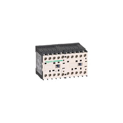
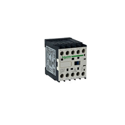
TeSys K reversing contactor, 3 poles (3NO), for motor control applications up to 9A/690V AC-3 (4kW@400V). It provides 24V DC coils, 2NC built-in auxiliary contacts, connection by solder pins for printed circuit board. For operating rates until 600 cycles/hour in AC-3 and environments until 50°C, it procures reliability and durability to standard applications. Compact (90mm width), DIN-rail mounting or screw fixing. With mechanical interlock (without electrical interlocking), this model has no pre-wired reversing power connections. Multi standards certified (IEC, UL, CSA, CCC, EAC).
Main
| Characteristic | Value(s) |
|---|---|
| Range | TeSys |
| product name | TeSys K |
| Product or Component Type | Reversing contactor |
| Device short name | LP2K |
| Device Application | Control |
| Contactor application | Motor control Resistive load |
| Utilisation category | AC-1 AC-4 AC-3 AC-3e |
| Device presentation | Preassembled with reversing power busbar |
| Poles description | 3P |
| power pole contact composition | 3 NO |
| [Ue] rated operational voltage | Power circuit 690 V AC 50/60 Hz Signalling circuit <= 690 V AC 50/60 Hz |
| [Ie] rated operational current | 20 A (at <122 °F (50 °C)) at <= 440 V AC AC-1 for power circuit 16 A (at <158 °F (70 °C)) at 690 V AC AC-1 for power circuit 9 A at <= 440 V AC AC-3 for power circuit 9 A at <= 440 V AC AC-3e for power circuit |
| Motor power kW | 2.2 kW 220...230 V AC 50/60 Hz 4 kW 380...415 V AC 50/60 Hz 4 kW 440 V AC 50/60 Hz 4 kW 480 V AC 50/60 Hz 4 kW 500...600 V AC 50/60 Hz 4 kW 660...690 V AC 50/60 Hz |
| Control circuit type | DC standard |
| [Uc] control circuit voltage | 24 V DC |
| Auxiliary contact composition | 1 NC |
| [Uimp] rated impulse withstand voltage | 8 kV |
| Overvoltage category | III |
| [Ith] conventional free air thermal current | 20 A (at 122 °F (50 °C)) for power circuit 10 A (at 122 °F (50 °C)) for signalling circuit |
| Irms rated making capacity | 110 A AC for power circuit conforming to NF C 63-110 110 A AC for power circuit conforming to IEC 60947 110 A AC for signalling circuit conforming to IEC 60947 |
| Rated breaking capacity | 110 A at 415 V conforming to IEC 60947 110 A at 440 V conforming to IEC 60947 80 A at 500 V conforming to IEC 60947 110 A at 220...230 V conforming to IEC 60947 110 A at 380...400 V conforming to IEC 60947 70 A at 660...690 V conforming to IEC 60947 |
| [Icw] rated short-time withstand current | 90 A 122 °F (50 °C) - 1 s for power circuit 85 A 122 °F (50 °C) - 5 s for power circuit 80 A 122 °F (50 °C) - 10 s for power circuit 60 A 122 °F (50 °C) - 30 s for power circuit 45 A 122 °F (50 °C) - 1 min for power circuit 40 A 122 °F (50 °C) - 3 min for power circuit 80 A - 1 s for signalling circuit 90 A - 500 ms for signalling circuit 110 A - 100 ms for signalling circuit 20 A 122 °F (50 °C) - >= 15 min for power circuit |
| Associated fuse rating | 25 A gG at <= 440 V for power circuit 25 A aM for power circuit 10 A gG for signalling circuit conforming to IEC 60947 10 A gG for signalling circuit conforming to VDE 0660 |
| Average impedance | 3 mOhm - Ith 20 A 50 Hz for power circuit |
| [Ui] rated insulation voltage | Power circuit 600 V UL 508 Power circuit 690 V IEC 60947-4-1 Signalling circuit 690 V IEC 60947-4-1 Signalling circuit 690 V IEC 60947-5-1 Signalling circuit 600 V UL 508 Power circuit 600 V CSA C22.2 No 14 Signalling circuit 600 V CSA C22.2 No 14 |
| Electrical durability | 1.3 Mcycles 9 A AC-3 <= 440 V 1.3 Mcycles 9 A AC-3e <= 440 V 0.16 Mcycles 20 A AC-1 <= 690 V 0.02 Mcycles 54 A AC-4 <= 440 V |
| Interlocking type | Mechanical |
| Mounting Support | Rail Plate |
| Standards | EN/IEC 60947-4-1 GB/T 14048.4 UL 60947-4-1 CSA C22.2 No 60947-4-1 JIS C8201-4-1 |
| Product Certifications | CB Scheme CCC UL CSA EAC CE UKCA |
| Connections - terminals | solder pins 0.001 in (0.035 mm)) |
| Operating time | 30...40 ms coil energisation and NO closing 10 ms coil de-energisation and NO opening |
| Safety reliability level | B10d = 1369863 cycles contactor with nominal load EN/ISO 13849-1 B10d = 20000000 cycles contactor with mechanical load EN/ISO 13849-1 |
| Mechanical durability | 5 Mcycles |
| Maximum operating rate | 3600 cyc/h |
Complementary
| Characteristic | Value(s) |
|---|---|
| Control circuit voltage limits | Operational: 0.8...1.15 Uc (at <122 °F (50 °C)) Drop-out: 0.1...0.75 Uc (at <122 °F (50 °C)) |
| Inrush power in W | 3 W 68 °F (20 °C)) |
| Hold-in power consumption in W | 3 W 68 °F (20 °C) |
| Heat dissipation | 3 W |
| Auxiliary contacts type | Instantaneous 1 NC |
| Minimum switching current | 5 mA for signalling circuit |
| Minimum switching voltage | 17 V for signalling circuit |
| Non overlap distance | 0.02 in (0.5 mm) |
| Insulation resistance | > 10 MOhm for signalling circuit |

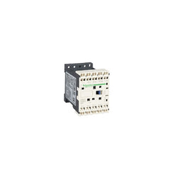
LP1K0910BD is a compact 3-pole TeSys K contactor from Schneider Electric for motor applications. Rated 9A AC-3 4kW@400V, it includes a 24V DC coil and 1NO auxiliary contact allowing easy integration to all control systems. LP1K0910BD is a 3-pole TeSys K contactor from Schneider Electric for simple motor applications rated up to 4kW@400V. Very compact, DIN-rail compatible, with connections by screw clamp terminals, it can be easily integrated into all control systems thanks to its 24V DC coil and 1NO built-in auxiliary contact. Available worldwide, it complies with multi-standards (IEC, UL, CSA, CCC, EAC, Marine). Very compact, 45mm wide, for DIN-rail and panel mounting. Ready for connection to all control systems thanks to a 24V DC control voltage and 1NO built-in auxiliary contact. Optimized for simple power applications. Can be completed with auxiliary contact blocks (LA1K, LA2K) and thermal relays (LR2K).
Main
| Characteristic | Value(s) |
|---|---|
| Range | TeSys |
| Product or Component Type | Contactor |
| Device short name | LP1K |
| Contactor application | Motor control Resistive load |
Complementary
| Characteristic | Value(s) |
|---|---|
| Utilisation category | AC-3 AC-3e AC-1 AC-4 |
| Poles description | 3P |
| power pole contact composition | 3 NO |
| [Ue] rated operational voltage | Power circuit <= 690 V AC <= 400 Hz Signalling circuit <= 690 V AC <= 400 Hz |
| [Ie] rated operational current | 9 A (at <140 °F (60 °C)) at <= 440 V AC AC-3 for power circuit 9 A (at <140 °F (60 °C)) at <= 440 V AC AC-3e for power circuit 20 A (at <140 °F (60 °C)) at <= 690 V AC AC-1 for power circuit |
| Control circuit type | DC standard |
| [Uc] control circuit voltage | 24 V DC |
| Motor power kW | 2.2 kW 220...230 V AC 50/60 Hz AC-3 4 kW 380...415 V AC 50/60 Hz AC-3 4 kW 440/690 V AC 50/60 Hz AC-3 2.2 kW 220...230 V AC 50/60 Hz AC-3e 4 kW 380...415 V AC 50/60 Hz AC-3e 4 kW 440/690 V AC 50/60 Hz AC-3e 2.2 kW 220...230 V AC 50/60 Hz AC-4 4 kW 380...415 V AC 50/60 Hz AC-4 4 kW 440/690 V AC 50/60 Hz AC-4 |
| Auxiliary contact composition | 1 NO |
| [Uimp] rated impulse withstand voltage | 8 kV |
| Overvoltage category | III |
| [Ith] conventional free air thermal current | 20 A (at 140 °F (60 °C)) for power circuit 10 A (at 122 °F (50 °C)) for signalling circuit |
| Irms rated making capacity | 110 A AC for power circuit conforming to IEC 60947 110 A AC for signalling circuit conforming to IEC 60947 |
| Rated breaking capacity | 110 A at 220...230 V conforming to IEC 60947 110 A at 380...400 V conforming to IEC 60947 110 A at 415 V conforming to IEC 60947 110 A at 440 V conforming to IEC 60947 80 A at 500 V conforming to IEC 60947 70 A at 660...690 V conforming to IEC 60947 |
| [Icw] rated short-time withstand current | 90 A 122 °F (50 °C) - 1 s for power circuit 85 A 122 °F (50 °C) - 5 s for power circuit 80 A 122 °F (50 °C) - 10 s for power circuit 60 A 122 °F (50 °C) - 30 s for power circuit 45 A 122 °F (50 °C) - 1 min for power circuit 40 A 122 °F (50 °C) - 3 min for power circuit 20 A 122 °F (50 °C) - >= 15 min for power circuit 80 A - 1 s for signalling circuit 90 A - 500 ms for signalling circuit 110 A - 100 ms for signalling circuit |
| Associated fuse rating | 25 A gG at <= 440 V for power circuit 25 A aM for power circuit 10 A gG for signalling circuit conforming to IEC 60947 10 A gG for signalling circuit conforming to VDE 0660 |
| Average impedance | 3 mOhm - Ith 20 A 50 Hz for power circuit |
| [Ui] rated insulation voltage | Power circuit 600 V UL 508 Power circuit 690 V IEC 60947-4-1 Signalling circuit 690 V IEC 60947-4-1 Signalling circuit 690 V IEC 60947-5-1 Signalling circuit 600 V UL 508 Power circuit 600 V CSA C22.2 No 14 Signalling circuit 600 V CSA C22.2 No 14 |
| Insulation resistance | > 10 MOhm for signalling circuit |
| Inrush power in W | 3 W 68 °F (20 °C)) |
| Hold-in power consumption in W | 3 W 68 °F (20 °C) |
| Heat dissipation | 1.3 W |
| Control circuit voltage limits | Operational: 0.8...1.15 Uc (at <122 °F (50 °C)) Drop-out: >= 0.10 Uc (at <122 °F (50 °C)) |
| Connections - terminals | screw clamp terminals 1 0.002â¦0.006 in² (1.5â¦4 mm²)solid screw clamp terminals 1 0.001â¦0.006 in² (0.75â¦4 mm²)flexible without cable end screw clamp terminals 1 0.0005â¦0.004 in² (0.34â¦2.5 mm²)flexible with cable end screw clamp terminals 2 0.002â¦0.006 in² (1.5â¦4 mm²)solid screw clamp terminals 2 0.001â¦0.006 in² (0.75â¦4 mm²)flexible without cable end screw clamp terminals 2 0.0005â¦0.002 in² (0.34â¦1.5 mm²)flexible with cable end Power circuit screw clamp terminals 2 0.002 in² (1.5 mm²)flexible with cable end |
| Maximum operating rate | 3600 cyc/h |
| Auxiliary contacts type | Instantaneous 1 NO |
| Minimum switching current | 5 mA for signalling circuit |
| Minimum switching voltage | 17 V for signalling circuit |
| Mounting Support | Rail Plate |
| Tightening torque | 7.08â¦11.5 lbf.in (0.8â¦1.3 N.m) screw clamp terminals Philips No 2 7.08â¦11.5 lbf.in (0.8â¦1.3 N.m) screw clamp terminals flat à 6 mm 7.08â¦11.5 lbf.in (0.8â¦1.3 N.m) screw clamp terminals pozidriv No 2 |
| Operating time | 30...40 ms coil energisation and NO closing 10 ms coil de-energisation and NO opening |
| Safety reliability level | B10d = 1369863 cycles contactor with nominal load EN/ISO 13849-1 B10d = 20000000 cycles contactor with mechanical load EN/ISO 13849-1 |
| Mechanical durability | 10 Mcycles |
| Electrical durability | 1.3 Mcycles 9 A AC-3 <= 440 V 1.3 Mcycles 9 A AC-3e <= 440 V 0.16 Mcycles 20 A AC-1 <= 690 V 0.02 Mcycles 54 A AC-4 <= 440 V |
| Height | 2.3 in (58 mm) |
| Width | 1.8 in (45 mm) |
| Depth | 2.2 in (57 mm) |
| Product Weight | 0.496 lb(US) (0.225 kg) |
TeSys K contactor - 3P - AC-3 <= 440 V 6 A - 1 NC aux. - 48 V DC coil
TeSys K contactor - 4P (2 NO + 2 NC) - AC-1 <= 440 V 20 A - 60 V DC coil

TeSys K reversing contactor - 3P - AC-3 <= 440 V 9 A - 1 NC - 24 V DC coil

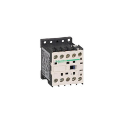
TeSys K contactor, 3 poles (3NO), for motor control applications up to 6A/690V AC-3 (2.2kW@400V). It provides a 24V DC coil, 1NO built-in auxiliary contact, connection by solder pins for printed circuit boards. For operating rates until 600 cycles/hour and environments until 50°C, it procures reliability and durability to standard applications. Very compact (45mm width), DIN-rail mounting or screw fixing. Multi standards certified (IEC, UL, CSA, CCC, EAC).
Main
| Characteristic | Value(s) |
|---|---|
| Range | TeSys |
| Product or Component Type | Contactor |
| Device short name | LP1K |
| Contactor application | Motor control |
Complementary
| Characteristic | Value(s) |
|---|---|
| Utilisation category | AC-3 AC-3e AC-4 |
| Poles description | 3P |
| power pole contact composition | 3 NO |
| [Ue] rated operational voltage | Power circuit <= 690 V AC <= 400 Hz Signalling circuit <= 690 V AC <= 400 Hz |
| [Ie] rated operational current | 6 A (at <140 °F (60 °C)) at <= 440 V AC AC-3 for power circuit 6 A (at <140 °F (60 °C)) at <= 440 V AC AC-3e for power circuit |
| Control circuit type | DC standard |
| [Uc] control circuit voltage | 24 V DC |
| Motor power kW | 1.5 kW 220...230 V AC 50/60 Hz AC-3 2.2 kW 380...415 V AC 50/60 Hz AC-3 3 kW 440/690 V AC 50/60 Hz AC-3 1.5 kW 220...230 V AC 50/60 Hz AC-3e 2.2 kW 380...415 V AC 50/60 Hz AC-3e 3 kW 440/690 V AC 50/60 Hz AC-3e 1.5 kW 220...230 V AC 50/60 Hz AC-4 2.2 kW 380...415 V AC 50/60 Hz AC-4 3 kW 440/690 V AC 50/60 Hz AC-4 |
| Auxiliary contact composition | 1 NO |
| [Uimp] rated impulse withstand voltage | 8 kV |
| Overvoltage category | III |
| [Ith] conventional free air thermal current | 20 A (at 140 °F (60 °C)) for power circuit 10 A (at 122 °F (50 °C)) for signalling circuit |
| Irms rated making capacity | 110 A AC for power circuit conforming to IEC 60947 110 A AC for signalling circuit conforming to IEC 60947 |
| Rated breaking capacity | 110 A at 220...230 V conforming to IEC 60947 110 A at 380...400 V conforming to IEC 60947 110 A at 415 V conforming to IEC 60947 110 A at 440 V conforming to IEC 60947 80 A at 500 V conforming to IEC 60947 70 A at 660...690 V conforming to IEC 60947 |
| [Icw] rated short-time withstand current | 90 A 122 °F (50 °C) - 1 s for power circuit 85 A 122 °F (50 °C) - 5 s for power circuit 80 A 122 °F (50 °C) - 10 s for power circuit 60 A 122 °F (50 °C) - 30 s for power circuit 45 A 122 °F (50 °C) - 1 min for power circuit 40 A 122 °F (50 °C) - 3 min for power circuit 20 A 122 °F (50 °C) - >= 15 min for power circuit 80 A - 1 s for signalling circuit 90 A - 500 ms for signalling circuit 110 A - 100 ms for signalling circuit |
| Associated fuse rating | 25 A gG at <= 440 V for power circuit 25 A aM for power circuit 10 A gG for signalling circuit conforming to IEC 60947 10 A gG for signalling circuit conforming to VDE 0660 |
| Average impedance | 3 mOhm - Ith 20 A 50 Hz for power circuit |
| [Ui] rated insulation voltage | Power circuit 600 V UL 508 Power circuit 690 V IEC 60947-4-1 Signalling circuit 690 V IEC 60947-4-1 Signalling circuit 690 V IEC 60947-5-1 Signalling circuit 600 V UL 508 Power circuit 600 V CSA C22.2 No 14 Signalling circuit 600 V CSA C22.2 No 14 |
| Insulation resistance | > 10 MOhm for signalling circuit |
| Inrush power in W | 3 W 68 °F (20 °C)) |
| Hold-in power consumption in W | 3 W 68 °F (20 °C) |
| Heat dissipation | 1.3 W |
| Control circuit voltage limits | Operational: 0.8...1.15 Uc (at <122 °F (50 °C)) Drop-out: >= 0.10 Uc (at <122 °F (50 °C)) |
| Connections - terminals | solder pins 0.001 in (0.035 mm)) |
| Maximum operating rate | 3600 cyc/h |
| Auxiliary contacts type | Instantaneous 1 NO |
| Minimum switching current | 5 mA for signalling circuit |
| Minimum switching voltage | 17 V for signalling circuit |
| Mounting Support | Printed circuit boards |
| Operating time | 30...40 ms coil energisation and NO closing 10 ms coil de-energisation and NO opening |
| Safety reliability level | B10d = 1369863 cycles contactor with nominal load EN/ISO 13849-1 B10d = 20000000 cycles contactor with mechanical load EN/ISO 13849-1 |
| Mechanical durability | 10 Mcycles |
| Electrical durability | 1.3 Mcycles 6 A AC-3 <= 440 V 1.3 Mcycles 6 A AC-3e <= 440 V 0.05 Mcycles 36 A AC-4 <= 440 V |
| Height | 2.3 in (58 mm) |
| Width | 1.8 in (45 mm) |
| Depth | 2.2 in (57 mm) |
| Product Weight | 0.496 lb(US) (0.225 kg) |

Main
| Characteristic | Value(s) |
|---|---|
| Range | TeSys |
| product name | TeSys K |
| Product or component type | Reversing contactor |
| Device short name | LP2K |
| Device application | Control |
| Contactor application | Motor control Resistive load |
| Utilisation category | AC-4 AC-3 AC-1 |
| Device presentation | Preassembled with reversing power busbar |
| Poles description | 3P |
| power pole contact composition | 3 NO |
| [Ue] rated operational voltage | Power circuit: 690 V AC 50/60 Hz Signalling circuit: <= 690 V AC 50/60 Hz |
| [Ie] rated operational current | 20 A (at <50 °C) at <= 440 V AC AC-1 for power circuit 16 A (at <70 °C) at 690 V AC AC-1 for power circuit 12 A at <= 440 V AC AC-3 for power circuit |
| Motor power kW | 4 kW at 480 V AC 50/60 Hz 4 kW at 500...600 V AC 50/60 Hz 4 kW at 660...690 V AC 50/60 Hz 3 kW at 220...230 V AC 50/60 Hz 5.5 kW at 380...415 V AC 50/60 Hz 5.5 kW at 440 V AC 50/60 Hz |
| Control circuit type | DC standard |
| [Uc] control circuit voltage | 110 V DC |
| Auxiliary contact composition | 1 NO |
| [Uimp] rated impulse withstand voltage | 8 kV |
| Overvoltage category | III |
| [Ith] conventional free air thermal current | 20 A (at 50 °C) for power circuit 10 A (at 50 °C) for signalling circuit |
| Irms rated making capacity | 110 A AC for signalling circuit conforming to IEC 60947 144 A AC for power circuit conforming to NF C 63-110 144 A AC for power circuit conforming to IEC 60947 |
| Rated breaking capacity | 110 A at 440 V conforming to IEC 60947 80 A at 500 V conforming to IEC 60947 70 A at 660...690 V conforming to IEC 60947 |
| [Icw] rated short-time withstand current | 115 A 50 °C - 1 s for power circuit 105 A 50 °C - 5 s for power circuit 100 A 50 °C - 10 s for power circuit 75 A 50 °C - 30 s for power circuit 55 A 50 °C - 1 min for power circuit 50 A 50 °C - 3 min for power circuit 80 A - 1 s for signalling circuit 90 A - 500 ms for signalling circuit 110 A - 100 ms for signalling circuit 25 A 50 °C - >= 15 min for power circuit |
| Associated fuse rating | 25 A gG at <= 440 V for power circuit 25 A aM for power circuit 10 A gG for signalling circuit conforming to IEC 60947 10 A gG for signalling circuit conforming to VDE 0660 |
| Average impedance | 3 mOhm - Ith 20 A 50 Hz for power circuit |
| [Ui] rated insulation voltage | Power circuit: 600 V conforming to UL 508 Power circuit: 690 V conforming to IEC 60947-4-1 Signalling circuit: 690 V conforming to IEC 60947-4-1 Signalling circuit: 690 V conforming to IEC 60947-5-1 Signalling circuit: 600 V conforming to UL 508 Power circuit: 600 V conforming to CSA C22.2 No 14 Signalling circuit: 600 V conforming to CSA C22.2 No 14 |
| Electrical durability | 0.3 Mcycles 20 A AC-1 at Ue <= 440 V 1.3 Mcycles 12 A AC-3 at Ue <= 440 V |
| Interlocking type | Mechanical |
| Mounting support | Plate Rail |
| Standards | EN/IEC 60947-4-1 GB/T 14048.4 UL 60947-4-1 CSA C22.2 No 60947-4-1 JIS C8201-4-1 |
| Product certifications | CB Scheme CCC UL CSA EAC CE UKCA |
| Connections - terminals | Screw clamp terminals 1 cable(s) 1.5â¦4 mm²solid Screw clamp terminals 1 cable(s) 0.75â¦4 mm²flexible without cable end Screw clamp terminals 1 cable(s) 0.34â¦2.5 mm²flexible with cable end Screw clamp terminals 2 cable(s) 1.5â¦4 mm²solid Screw clamp terminals 2 cable(s) 0.75â¦4 mm²flexible without cable end Screw clamp terminals 2 cable(s) 0.34â¦1.5 mm²flexible with cable end |
| Tightening torque | 0.8â¦1.3 N.m - on screw clamp terminals Philips No 2 0.8â¦1.3 N.m - on screw clamp terminals flat à 6 mm |
| Operating time | 30...40 ms coil energisation and NO closing 10 ms coil de-energisation and NO opening |
| Safety reliability level | B10d = 1369863 cycles contactor with nominal load conforming to EN/ISO 13849-1 B10d = 20000000 cycles contactor with mechanical load conforming to EN/ISO 13849-1 |
| Mechanical durability | 5 Mcycles |
| Maximum operating rate | 3600 cyc/h |
Complementary
| Characteristic | Value(s) |
|---|---|
| Control circuit voltage limits | Operational: 0.8...1.15 Uc (at <50 °C) Drop-out: 0.1...0.75 Uc (at <50 °C) |
| Inrush power in W | 3 W (at 20 °C) |
| Hold-in power consumption in W | 3 W at 20 °C |
| Heat dissipation | 3 W |
| Auxiliary contacts type | type instantaneous 1 NO |
| Minimum switching current | 5 mA for signalling circuit |
| Minimum switching voltage | 17 V for signalling circuit |
| Non overlap distance | 0.5 mm |
| Insulation resistance | > 10 MOhm for signalling circuit |
TeSys K contactor - 3P - AC-3 <= 440 V 6 A - 1 NC aux. - 110 V DC coil

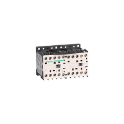
LP2K0901ED is a compact 3-pole TeSys K reversing contactor from Schneider Electric for motor applications. Rated 9A AC-3 4kW@400V, it includes a 48V DC coil, 1NC auxiliary contact, a mechanical interlock and a pre-wired reversing circuit. LP2K0901ED is a 3-pole TeSys K reversing contactor from Schneider Electric for simple motor applications rated up to 4kW@400V. Very compact, DIN-rail compatible, it is assembled with a mechanical interlock and a pre-wired reversing circuit. It can be easily integrated into all control systems thanks to its 48V DC coil and 1NC built-in auxiliary contact. Available worldwide, it complies with multi-standards (IEC, UL, CSA, CCC, EAC, Marine). Very compact, 90mm wide, for DIN-rail and panel mounting. Assembled with mechanical interlock and pre-wired reversing circuit. Ready for connection to all control systems thanks to a 48V DC control voltage and 2NC built-in auxiliary contact. Can be completed with auxiliary contact blocks (LA1K, LA2K) and thermal relays (LR2K).
Main
| Characteristic | Value(s) |
|---|---|
| Range | TeSys |
| product name | TeSys K |
| Product or Component Type | Reversing contactor |
| Device short name | LP2K |
| Device Application | Control |
| Contactor application | Motor control Resistive load |
| Utilisation category | AC-3 AC-3e AC-4 AC-1 |
| Device presentation | Preassembled with reversing power busbar |
| Poles description | 3P |
| power pole contact composition | 3 NO |
| [Ue] rated operational voltage | Power circuit 690 V AC 50/60 Hz Signalling circuit <= 690 V AC 50/60 Hz |
| [Ie] rated operational current | 9 A (at <140 °F (60 °C)) at <= 440 V AC AC-3 for power circuit 9 A (at <140 °F (60 °C)) at <= 440 V AC AC-3e for power circuit 20 A (at <140 °F (60 °C)) at <= 690 V AC AC-1 for power circuit |
| Motor power kW | 2.2 kW 220...230 V AC 50/60 Hz 4 kW 380...415 V AC 50/60 Hz 4 kW 440/690 V AC 50/60 Hz |
| Control circuit type | DC standard |
| [Uc] control circuit voltage | 48 V DC |
| Auxiliary contact composition | 1 NC |
| [Uimp] rated impulse withstand voltage | 8 kV |
| Overvoltage category | III |
| [Ith] conventional free air thermal current | 20 A (at 140 °F (60 °C)) for power circuit 10 A (at 122 °F (50 °C)) for signalling circuit |
| Irms rated making capacity | 110 A AC for power circuit conforming to IEC 60947 110 A AC for signalling circuit conforming to IEC 60947 |
| Rated breaking capacity | 110 A at 220...230 V conforming to IEC 60947 110 A at 380...400 V conforming to IEC 60947 110 A at 415 V conforming to IEC 60947 110 A at 440 V conforming to IEC 60947 80 A at 500 V conforming to IEC 60947 70 A at 660...690 V conforming to IEC 60947 |
| [Icw] rated short-time withstand current | 90 A 122 °F (50 °C) - 1 s for power circuit 85 A 122 °F (50 °C) - 5 s for power circuit 80 A 122 °F (50 °C) - 10 s for power circuit 60 A 122 °F (50 °C) - 30 s for power circuit 45 A 122 °F (50 °C) - 1 min for power circuit 40 A 122 °F (50 °C) - 3 min for power circuit 20 A 122 °F (50 °C) - >= 15 min for power circuit 80 A - 1 s for signalling circuit 90 A - 500 ms for signalling circuit 110 A - 100 ms for signalling circuit |
| Associated fuse rating | 25 A gG at <= 440 V for power circuit 25 A aM for power circuit 10 A gG for signalling circuit conforming to IEC 60947 10 A gG for signalling circuit conforming to VDE 0660 |
| Average impedance | 3 mOhm - Ith 20 A 50 Hz for power circuit |
| [Ui] rated insulation voltage | Power circuit 600 V UL 508 Power circuit 690 V IEC 60947-4-1 Signalling circuit 690 V IEC 60947-4-1 Signalling circuit 690 V IEC 60947-5-1 Signalling circuit 600 V UL 508 Power circuit 600 V CSA C22.2 No 14 Signalling circuit 600 V CSA C22.2 No 14 |
| Electrical durability | 1.3 Mcycles 9 A AC-3 <= 440 V 1.3 Mcycles 9 A AC-3e <= 440 V 0.16 Mcycles 20 A AC-1 <= 690 V 0.02 Mcycles 54 A AC-4 <= 440 V |
| Interlocking type | Mechanical |
| Mounting Support | Rail Plate |
| Standards | EN/IEC 60947-4-1 GB/T 14048.4 UL 60947-4-1 CSA C22.2 No 60947-4-1 JIS C8201-4-1 |
| Product Certifications | CB Scheme CCC UL CSA EAC CE UKCA |
| Connections - terminals | screw clamp terminals 1 0.002â¦0.006 in² (1.5â¦4 mm²)solid screw clamp terminals 1 0.001â¦0.006 in² (0.75â¦4 mm²)flexible without cable end screw clamp terminals 1 0.0005â¦0.004 in² (0.34â¦2.5 mm²)flexible with cable end screw clamp terminals 2 0.002â¦0.006 in² (1.5â¦4 mm²)solid screw clamp terminals 2 0.001â¦0.006 in² (0.75â¦4 mm²)flexible without cable end screw clamp terminals 2 0.0005â¦0.002 in² (0.34â¦1.5 mm²)flexible with cable end |
| Tightening torque | 7.08â¦11.5 lbf.in (0.8â¦1.3 N.m) screw clamp terminals Philips No 2 7.08â¦11.5 lbf.in (0.8â¦1.3 N.m) screw clamp terminals flat à 6 mm 7.08â¦11.5 lbf.in (0.8â¦1.3 N.m) screw clamp terminals pozidriv No 2 |
| Operating time | 30...40 ms coil energisation and NO closing 10 ms coil de-energisation and NO opening |
| Safety reliability level | B10d = 1369863 cycles contactor with nominal load EN/ISO 13849-1 B10d = 20000000 cycles contactor with mechanical load EN/ISO 13849-1 |
| Mechanical durability | 5 Mcycles |
| Maximum operating rate | 3600 cyc/h |
Complementary
| Characteristic | Value(s) |
|---|---|
| Control circuit voltage limits | Operational: 0.8...1.15 Uc (at <122 °F (50 °C)) Drop-out: 0.1...0.75 Uc (at <122 °F (50 °C)) |
| Inrush power in W | 3 W 68 °F (20 °C)) |
| Hold-in power consumption in W | 3 W 68 °F (20 °C) |
| Heat dissipation | 3 W |
| Auxiliary contacts type | Instantaneous 1 NC |
| Minimum switching current | 5 mA for signalling circuit |
| Minimum switching voltage | 17 V for signalling circuit |
| Non overlap distance | 0.02 in (0.5 mm) |
| Insulation resistance | > 10 MOhm for signalling circuit |

TeSys D contactors have been designed for perfect integration into control systems. They can be used to create motor starters for almost any type of application. TeSys D contactors are available in 13 contactor ratings for inductive motor applications up to 150 full-load amps and resistive loads up to 200 amps. This 4 pole IEC contactor can be mounted on DIN rail or mounted directly to a panel. Contactor has two normally open and two normally closed power contacts. Power contacts have a 125A resistive load rating. Contactor is supplied with a 24 VDC coil. Screw clamp terminals are used for load and auxiliary connections. An extensive line of accessories makes it easy to meet the requirements of most applications. The contactor is 5.00 inches tall, 3.78 inches wide and 7.72 inches deep. It weighs 6.42 lbs. Contactor is certified to UL, CSA, IEC, CCC, EAC and Marine standards.
Main
| Characteristic | Value(s) |
|---|---|
| Range | TeSys |
| Range of Product | TeSys Deca |
| Product or Component Type | Contactor |
| Device short name | LP1D |
| Contactor application | Resistive load |
| Utilisation category | AC-1 |
| Poles description | 4P |
| [Ue] rated operational voltage | Power circuit <= 690 V AC 25...400 Hz |
| [Ie] rated operational current | 125 A (at <140 °F (60 °C)) at <= 440 V AC AC-1 for power circuit |
| [Uc] control circuit voltage | 24 V DC |
Complementary
| Characteristic | Value(s) |
|---|---|
| Compatibility code | LP1D |
| Pole contact composition | 2 NO + 2 NC |
| Protective cover | With |
| [Ith] conventional free air thermal current | 125 A (at 140 °F (60 °C)) for power circuit |
| Irms rated making capacity | 1100 A at 440 V for power circuit conforming to IEC 60947 |
| Rated breaking capacity | 1100 A at 440 V for power circuit conforming to IEC 60947 |
| [Icw] rated short-time withstand current | 135 A 104 °F (40 °C) - 10 min for power circuit 320 A 104 °F (40 °C) - 1 min for power circuit 640 A 104 °F (40 °C) - 10 s for power circuit 990 A 104 °F (40 °C) - 1 s for power circuit |
| Associated fuse rating | 200 A gG at <= 690 V coordination type 1 for power circuit 160 A gG at <= 690 V coordination type 2 for power circuit |
| Average impedance | 0.8 mOhm - Ith 125 A 50 Hz for power circuit |
| Power dissipation per pole | 12.5 W AC-1 |
| [Ui] rated insulation voltage | Power circuit 600 V CSA Power circuit 600 V UL Power circuit 1000 V IEC 60947-4-1 |
| Overvoltage category | III |
| pollution degree | 3 |
| [Uimp] rated impulse withstand voltage | 8 kV IEC 60947 |
| Safety reliability level | B10d = 1369863 cycles contactor with nominal load EN/ISO 13849-1 B10d = 20000000 cycles contactor with mechanical load EN/ISO 13849-1 |
| Mechanical durability | 10 Mcycles |
| Electrical durability | 0.8 Mcycles 125 A AC-1 <= 440 V |
| Control circuit type | DC DC standard |
| Coil technology | Without built-in suppressor module |
| Control circuit voltage limits | 0.1...0.3 Uc (-40â¦131 °F (-40â¦55 °C)):drop-out DC 0.85...1.1 Uc (-40â¦131 °F (-40â¦55 °C)):operational DC |
| Inrush power in W | 22 W 68 °F (20 °C)) |
| Hold-in power consumption in W | 22 W 68 °F (20 °C) |
| Operating time | 6...20 ms opening 20...35 ms closing |
| Time constant | 75 ms |
| Maximum operating rate | 3600 cyc/h at 60 °C |
| Connections - terminals | Control circuit: screw clamp terminals 1 0.002â¦0.006 in² (1â¦4 mm²) - cable stiffness: flexible without cable end Control circuit: screw clamp terminals 2 0.002â¦0.006 in² (1â¦4 mm²) - cable stiffness: flexible without cable end Control circuit: screw clamp terminals 2 0.002â¦0.004 in² (1â¦2.5 mm²) - cable stiffness: flexible with cable end Control circuit: screw clamp terminals 1 0.002â¦0.006 in² (1â¦4 mm²) - cable stiffness: solid Control circuit: screw clamp terminals 2 0.002â¦0.006 in² (1â¦4 mm²) - cable stiffness: solid Power circuit: connector 1 0.006â¦0.08 in² (4â¦50 mm²) - cable stiffness: flexible without cable end Power circuit: connector 2 0.006â¦0.04 in² (4â¦25 mm²) - cable stiffness: flexible without cable end Power circuit: connector 1 0.006â¦0.08 in² (4â¦50 mm²) - cable stiffness: flexible with cable end Power circuit: connector 2 0.006â¦0.02 in² (4â¦16 mm²) - cable stiffness: flexible with cable end Power circuit: connector 1 0.006â¦0.08 in² (4â¦50 mm²) - cable stiffness: solid Power circuit: connector 2 0.006â¦0.04 in² (4â¦25 mm²) - cable stiffness: solid Control circuit: screw clamp terminals 1 0.002â¦0.004 in² (1â¦2.5 mm²) - cable stiffness: flexible with cable end |
| Tightening torque | Control circuit 10.6 lbf.in (1.2 N.m) screw clamp terminals flat à 6 mm Control circuit 10.6 lbf.in (1.2 N.m) screw clamp terminals Philips No 2 Power circuit 106.2 lbf.in (12 N.m) connector flat à 6 to à 8 mm Power circuit 106.2 lbf.in (12 N.m) connector hexagonal 0.2 in (4 mm) Control circuit 10.6 lbf.in (1.2 N.m) screw clamp terminals pozidriv No 2 |
| Mounting Support | Plate Rail |

TeSys K contactor - 3P - AC-3 <= 440 V 6 A - 1 NC aux. - 24 V DC coil

TeSys K contactor - 3P - AC-3 <= 440 V 9 A - 1 NC aux. - 72 V DC coil

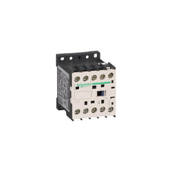
TeSys K contactor, 4 poles (2NO+2NC), for non-inductive load control applications up to 20A/690V AC-1. It provides a 24V DC coil, without built-in auxiliary contact, connection by screw clamp terminals. For operating rates until 600 cycles/hour and environments until 50°C, it procures reliability and durability to standard applications. Very compact (45mm width), DIN-rail mounting or screw fixing. Multi standards certified (IEC, UL, CSA, CCC, EAC).
Main
| Characteristic | Value(s) |
|---|---|
| Range | TeSys |
| Product or Component Type | Contactor |
| Device short name | LP1K |
| Contactor application | Resistive load |
Complementary
| Characteristic | Value(s) |
|---|---|
| Utilisation category | AC-1 |
| Poles description | 4P |
| power pole contact composition | 2 NO + 2 NC |
| [Ue] rated operational voltage | Power circuit <= 690 V AC <= 400 Hz Signalling circuit <= 690 V AC <= 400 Hz |
| [Ie] rated operational current | 20 A (at <140 °F (60 °C)) at <= 690 V AC AC-1 for power circuit |
| Control circuit type | DC standard |
| [Uc] control circuit voltage | 24 V DC |
| [Uimp] rated impulse withstand voltage | 8 kV |
| Overvoltage category | III |
| [Ith] conventional free air thermal current | 20 A (at 140 °F (60 °C)) for power circuit 10 A (at 122 °F (50 °C)) for signalling circuit |
| Irms rated making capacity | 110 A AC for power circuit conforming to IEC 60947 |
| Rated breaking capacity | 110 A at 220...230 V conforming to IEC 60947 110 A at 380...400 V conforming to IEC 60947 110 A at 415 V conforming to IEC 60947 110 A at 440 V conforming to IEC 60947 80 A at 500 V conforming to IEC 60947 70 A at 660...690 V conforming to IEC 60947 |
| [Icw] rated short-time withstand current | 90 A 122 °F (50 °C) - 1 s for power circuit 85 A 122 °F (50 °C) - 5 s for power circuit 80 A 122 °F (50 °C) - 10 s for power circuit 60 A 122 °F (50 °C) - 30 s for power circuit 45 A 122 °F (50 °C) - 1 min for power circuit 40 A 122 °F (50 °C) - 3 min for power circuit 20 A 122 °F (50 °C) - >= 15 min for power circuit |
| Associated fuse rating | 25 A gG at <= 440 V for power circuit 25 A aM for power circuit |
| Average impedance | 3 mOhm - Ith 20 A 50 Hz for power circuit |
| [Ui] rated insulation voltage | Power circuit 600 V UL 508 Power circuit 690 V IEC 60947-4-1 Power circuit 600 V CSA C22.2 No 14 |
| Inrush power in W | 3 W 68 °F (20 °C)) |
| Hold-in power consumption in W | 3 W 68 °F (20 °C) |
| Heat dissipation | 1.3 W |
| Control circuit voltage limits | Operational: 0.8...1.15 Uc (at <122 °F (50 °C)) Drop-out: >= 0.10 Uc (at <122 °F (50 °C)) |
| Connections - terminals | screw clamp terminals 1 0.002â¦0.006 in² (1.5â¦4 mm²)solid screw clamp terminals 1 0.001â¦0.006 in² (0.75â¦4 mm²)flexible without cable end screw clamp terminals 1 0.0005â¦0.004 in² (0.34â¦2.5 mm²)flexible with cable end screw clamp terminals 2 0.002â¦0.006 in² (1.5â¦4 mm²)solid screw clamp terminals 2 0.001â¦0.006 in² (0.75â¦4 mm²)flexible without cable end screw clamp terminals 2 0.0005â¦0.002 in² (0.34â¦1.5 mm²)flexible with cable end Power circuit screw clamp terminals 2 0.002 in² (1.5 mm²)flexible with cable end |
| Maximum operating rate | 3600 cyc/h |
| Mounting Support | Rail Plate |
| Tightening torque | 7.08â¦11.5 lbf.in (0.8â¦1.3 N.m) screw clamp terminals Philips No 2 7.08â¦11.5 lbf.in (0.8â¦1.3 N.m) screw clamp terminals flat à 6 mm |
| Operating time | 30...40 ms coil energisation and NO closing 10 ms coil de-energisation and NO opening 25...35 ms coil energisation and NC opening 15 ms coil de-energisation and NC closing |
| Safety reliability level | B10d = 1369863 cycles contactor with nominal load EN/ISO 13849-1 B10d = 20000000 cycles contactor with mechanical load EN/ISO 13849-1 |
| Mechanical durability | 10 Mcycles |
| Electrical durability | 0.16 Mcycles 20 A AC-1 <= 690 V |
| Height | 2.3 in (58 mm) |
| Width | 1.8 in (45 mm) |
| Depth | 2.2 in (57 mm) |
| Product Weight | 0.496 lb(US) (0.225 kg) |

TeSys K contactor - 3P - AC-3 <= 440 V 9 A - 1 NC aux. - 24 V DC coil
TeSys K contactor, 4 poles (4NO), for non-inductive load control applications up to 20A/690V AC-1. It provides a 24V DC coil, without built-in auxiliary contact, connection by solder pins for printed circuit boards. For operating rates until 600 cycles/hour and environments until 50°C, it procures reliability and durability to standard applications. Very compact (45mm width), DIN-rail mounting or screw fixing. Multi standards certified (IEC, UL, CSA, CCC, EAC).
Main
| Characteristic | Value(s) |
|---|---|
| Range | TeSys |
| Product or Component Type | Contactor |
| Contactor application | Resistive load |
Complementary
| Characteristic | Value(s) |
|---|---|
| Utilisation category | AC-1 |
| Poles description | 4P |
| power pole contact composition | 4 NO |
| [Ue] rated operational voltage | Power circuit <= 690 V AC <= 400 Hz Signalling circuit <= 690 V AC <= 400 Hz |
| [Ie] rated operational current | 20 A (at <140 °F (60 °C)) at <= 690 V AC AC-1 for power circuit |
| Control circuit type | DC standard |
| [Uc] control circuit voltage | 24 V DC |
| [Uimp] rated impulse withstand voltage | 8 kV |
| Overvoltage category | III |
| [Ith] conventional free air thermal current | 16 A (at 140 °F (60 °C)) for power circuit 10 A (at 122 °F (50 °C)) for signalling circuit |
| Irms rated making capacity | 110 A AC for power circuit conforming to IEC 60947 |
| Rated breaking capacity | 110 A at 220...230 V conforming to IEC 60947 110 A at 380...400 V conforming to IEC 60947 110 A at 415 V conforming to IEC 60947 110 A at 440 V conforming to IEC 60947 80 A at 500 V conforming to IEC 60947 70 A at 660...690 V conforming to IEC 60947 |
| [Icw] rated short-time withstand current | 90 A 122 °F (50 °C) - 1 s for power circuit 85 A 122 °F (50 °C) - 5 s for power circuit 80 A 122 °F (50 °C) - 10 s for power circuit 60 A 122 °F (50 °C) - 30 s for power circuit 45 A 122 °F (50 °C) - 1 min for power circuit 40 A 122 °F (50 °C) - 3 min for power circuit 20 A 122 °F (50 °C) - >= 15 min for power circuit |
| Associated fuse rating | 25 A gG at <= 440 V for power circuit 25 A aM for power circuit |
| Average impedance | 3 mOhm - Ith 20 A 50 Hz for power circuit |
| [Ui] rated insulation voltage | Power circuit 600 V UL 508 Power circuit 690 V IEC 60947-4-1 Power circuit 600 V CSA C22.2 No 14 |
| Inrush power in W | 3 W 68 °F (20 °C)) |
| Hold-in power consumption in W | 3 W 68 °F (20 °C) |
| Heat dissipation | 1.3 W |
| Control circuit voltage limits | Operational: 0.8...1.15 Uc (at <122 °F (50 °C)) Drop-out: >= 0.10 Uc (at <122 °F (50 °C)) |
| Connections - terminals | solder pins 0.001 in (0.035 mm)) |
| Maximum operating rate | 3600 cyc/h |
| Mounting Support | Printed circuit boards |
| Operating time | 30...40 ms coil energisation and NO closing 10 ms coil de-energisation and NO opening |
| Safety reliability level | B10d = 1369863 cycles contactor with nominal load EN/ISO 13849-1 B10d = 20000000 cycles contactor with mechanical load EN/ISO 13849-1 |
| Mechanical durability | 10 Mcycles |
| Electrical durability | 0.16 Mcycles 20 A AC-1 <= 690 V |
| Height | 2.3 in (58 mm) |
| Width | 1.8 in (45 mm) |
| Depth | 2.2 in (57 mm) |
| Product Weight | 0.496 lb(US) (0.225 kg) |

Main
| Characteristic | Value(s) |
|---|---|
| Range | TeSys |
| product name | TeSys K |
| Product or Component Type | Reversing contactor |
| Device short name | LP5K |
| Device Application | Control |
| Contactor application | Resistive load Motor control |
| Utilisation category | AC-4 AC-1 AC-3 AC-3e |
| Device presentation | Preassembled with reversing power busbar |
| Poles description | 3P |
| power pole contact composition | 3 NO |
| [Ue] rated operational voltage | Power circuit 690 V AC 50/60 Hz Signalling circuit <= 690 V AC 50/60 Hz |
| [Ie] rated operational current | 20 A (at <122 °F (50 °C)) at <= 440 V AC AC-1 for power circuit 16 A (at <158 °F (70 °C)) at 690 V AC AC-1 for power circuit 12 A at <= 440 V AC AC-3 for power circuit 12 A at <= 440 V AC AC-3e for power circuit |
| Motor power kW | 4 kW 480 V AC 50/60 Hz 4 kW 500...600 V AC 50/60 Hz 4 kW 660...690 V AC 50/60 Hz 3 kW 220...230 V AC 50/60 Hz 5.5 kW 380...415 V AC 50/60 Hz 5.5 kW 440 V AC 50/60 Hz |
| Control circuit type | DC low consumption |
| [Uc] control circuit voltage | 72 V DC |
| Auxiliary contact composition | 1 NC |
| [Uimp] rated impulse withstand voltage | 8 kV |
| Overvoltage category | III |
| [Ith] conventional free air thermal current | 20 A (at 122 °F (50 °C)) for power circuit 10 A (at 122 °F (50 °C)) for signalling circuit |
| Irms rated making capacity | 110 A AC for signalling circuit conforming to IEC 60947 144 A AC for power circuit conforming to NF C 63-110 144 A AC for power circuit conforming to IEC 60947 |
| Rated breaking capacity | 110 A at 440 V conforming to IEC 60947 80 A at 500 V conforming to IEC 60947 70 A at 660...690 V conforming to IEC 60947 |
| [Icw] rated short-time withstand current | 115 A 122 °F (50 °C) - 1 s for power circuit 105 A 122 °F (50 °C) - 5 s for power circuit 100 A 122 °F (50 °C) - 10 s for power circuit 75 A 122 °F (50 °C) - 30 s for power circuit 55 A 122 °F (50 °C) - 1 min for power circuit 50 A 122 °F (50 °C) - 3 min for power circuit 80 A - 1 s for signalling circuit 90 A - 500 ms for signalling circuit 110 A - 100 ms for signalling circuit 25 A 122 °F (50 °C) - >= 15 min for power circuit |
| Associated fuse rating | 25 A gG at <= 440 V for power circuit 25 A aM for power circuit 10 A gG for signalling circuit conforming to IEC 60947 10 A gG for signalling circuit conforming to VDE 0660 |
| Average impedance | 3 mOhm - Ith 20 A 50 Hz for power circuit |
| [Ui] rated insulation voltage | Power circuit 600 V UL 508 Power circuit 690 V IEC 60947-4-1 Signalling circuit 690 V IEC 60947-4-1 Signalling circuit 690 V IEC 60947-5-1 Signalling circuit 600 V UL 508 Power circuit 600 V CSA C22.2 No 14 Signalling circuit 600 V CSA C22.2 No 14 |
| Electrical durability | 1.3 Mcycles 12 A AC-3 <= 440 V 1.3 Mcycles 12 A AC-3e <= 440 V 0.3 Mcycles 20 A AC-1 <= 690 V 0.02 Mcycles 72 A AC-4 <= 440 V |
| Interlocking type | Mechanical |
| Mounting Support | Plate Rail |
| Standards | EN/IEC 60947-4-1 GB/T 14048.4 UL 60947-4-1 CSA C22.2 No 60947-4-1 JIS C8201-4-1 |
| Product Certifications | CB Scheme CCC UL CSA EAC CE UKCA |
| Connections - terminals | screw clamp terminals 1 0.002â¦0.006 in² (1.5â¦4 mm²)solid screw clamp terminals 1 0.001â¦0.006 in² (0.75â¦4 mm²)flexible without cable end screw clamp terminals 1 0.0005â¦0.004 in² (0.34â¦2.5 mm²)flexible with cable end screw clamp terminals 2 0.002â¦0.006 in² (1.5â¦4 mm²)solid screw clamp terminals 2 0.001â¦0.006 in² (0.75â¦4 mm²)flexible without cable end screw clamp terminals 2 0.0005â¦0.002 in² (0.34â¦1.5 mm²)flexible with cable end |
| Tightening torque | 7.08â¦11.5 lbf.in (0.8â¦1.3 N.m) screw clamp terminals Philips No 2 7.08â¦11.5 lbf.in (0.8â¦1.3 N.m) screw clamp terminals flat à 6 mm 7.08â¦11.5 lbf.in (0.8â¦1.3 N.m) screw clamp terminals pozidriv No 2 |
| Operating time | 10...20 ms coil de-energisation and NO opening 30...40 ms coil energisation and NO closing |
| Safety reliability level | B10d = 1369863 cycles contactor with nominal load EN/ISO 13849-1 B10d = 20000000 cycles contactor with mechanical load EN/ISO 13849-1 |
| Mechanical durability | 5 Mcycles |
| Maximum operating rate | 3600 cyc/h |
Complementary
| Characteristic | Value(s) |
|---|---|
| Coil technology | Built-in bidirectional peak limiting diode suppressor |
| Control circuit voltage limits | Operational: 0.7...1.30 Uc (at <122 °F (50 °C)) Drop-out: 0.1...0.7 Uc (at <122 °F (50 °C)) |
| Inrush power in W | 1.8 W 68 °F (20 °C)) |
| Hold-in power consumption in W | 1.8 W 68 °F (20 °C) |
| Heat dissipation | 1.8 W |
| Auxiliary contacts type | Instantaneous 1 NC |
| Minimum switching current | 5 mA for signalling circuit |
| Minimum switching voltage | 17 V for signalling circuit |
| Non overlap distance | 0.02 in (0.5 mm) |
| Insulation resistance | > 10 MOhm for signalling circuit |

TeSys K contactor - 4P (2 NO + 2 NC) - AC-1 <= 440 V 20 A - 24 V DC coil

TeSys K contactor - 3P - AC-3 <= 440 V 6 A - 1 NO aux. - 72 V DC coil

TeSys K contactor - 3P - AC-3 <= 440 V 9 A - 1 NO aux. - 24 V DC coil

TeSys K contactor, 4 poles (4NO), for non-inductive load control applications up to 20A/690V AC-1. It provides a 48V DC coil, without built-in auxiliary contact, connection by screw clamp terminals. For operating rates until 600 cycles/hour and environments until 50°C, it procures reliability and durability to standard applications. Very compact (45mm width), DIN-rail mounting or screw fixing. Multi standards certified (IEC, UL, CSA, CCC, EAC).
Main
| Characteristic | Value(s) |
|---|---|
| Range | TeSys |
| Product or Component Type | Contactor |
| Device short name | LP1K |
| Contactor application | Resistive load |
Complementary
| Characteristic | Value(s) |
|---|---|
| Utilisation category | AC-1 |
| Poles description | 4P |
| power pole contact composition | 4 NO |
| [Ue] rated operational voltage | Power circuit <= 690 V AC <= 400 Hz Signalling circuit <= 690 V AC <= 400 Hz |
| [Ie] rated operational current | 20 A (at <140 °F (60 °C)) at <= 690 V AC AC-1 for power circuit |
| Control circuit type | DC standard |
| [Uc] control circuit voltage | 48 V DC |
| [Uimp] rated impulse withstand voltage | 8 kV |
| Overvoltage category | III |
| [Ith] conventional free air thermal current | 20 A (at 140 °F (60 °C)) for power circuit 10 A (at 122 °F (50 °C)) for signalling circuit |
| Irms rated making capacity | 110 A AC for power circuit conforming to IEC 60947 |
| Rated breaking capacity | 110 A at 220...230 V conforming to IEC 60947 110 A at 380...400 V conforming to IEC 60947 110 A at 415 V conforming to IEC 60947 110 A at 440 V conforming to IEC 60947 80 A at 500 V conforming to IEC 60947 70 A at 660...690 V conforming to IEC 60947 |
| [Icw] rated short-time withstand current | 90 A 122 °F (50 °C) - 1 s for power circuit 85 A 122 °F (50 °C) - 5 s for power circuit 80 A 122 °F (50 °C) - 10 s for power circuit 60 A 122 °F (50 °C) - 30 s for power circuit 45 A 122 °F (50 °C) - 1 min for power circuit 40 A 122 °F (50 °C) - 3 min for power circuit 20 A 122 °F (50 °C) - >= 15 min for power circuit |
| Associated fuse rating | 25 A gG at <= 440 V for power circuit 25 A aM for power circuit |
| Average impedance | 3 mOhm - Ith 20 A 50 Hz for power circuit |
| [Ui] rated insulation voltage | Power circuit 600 V UL 508 Power circuit 690 V IEC 60947-4-1 Power circuit 600 V CSA C22.2 No 14 |
| Inrush power in W | 3 W 68 °F (20 °C)) |
| Hold-in power consumption in W | 3 W 68 °F (20 °C) |
| Heat dissipation | 1.3 W |
| Control circuit voltage limits | Operational: 0.8...1.15 Uc (at <122 °F (50 °C)) Drop-out: >= 0.10 Uc (at <122 °F (50 °C)) |
| Connections - terminals | screw clamp terminals 1 0.002â¦0.006 in² (1.5â¦4 mm²)solid screw clamp terminals 1 0.001â¦0.006 in² (0.75â¦4 mm²)flexible without cable end screw clamp terminals 1 0.0005â¦0.004 in² (0.34â¦2.5 mm²)flexible with cable end screw clamp terminals 2 0.002â¦0.006 in² (1.5â¦4 mm²)solid screw clamp terminals 2 0.001â¦0.006 in² (0.75â¦4 mm²)flexible without cable end screw clamp terminals 2 0.0005â¦0.002 in² (0.34â¦1.5 mm²)flexible with cable end Power circuit screw clamp terminals 2 0.002 in² (1.5 mm²)flexible with cable end |
| Maximum operating rate | 3600 cyc/h |
| Mounting Support | Rail Plate |
| Tightening torque | 7.08â¦11.5 lbf.in (0.8â¦1.3 N.m) screw clamp terminals Philips No 2 7.08â¦11.5 lbf.in (0.8â¦1.3 N.m) screw clamp terminals flat à 6 mm 7.08â¦11.5 lbf.in (0.8â¦1.3 N.m) screw clamp terminals pozidriv No 2 |
| Operating time | 30...40 ms coil energisation and NO closing 10 ms coil de-energisation and NO opening |
| Safety reliability level | B10d = 1369863 cycles contactor with nominal load EN/ISO 13849-1 B10d = 20000000 cycles contactor with mechanical load EN/ISO 13849-1 |
| Mechanical durability | 10 Mcycles |
| Electrical durability | 0.16 Mcycles 20 A AC-1 <= 690 V |
| Height | 2.3 in (58 mm) |
| Width | 1.8 in (45 mm) |
| Depth | 2.2 in (57 mm) |
| Product Weight | 0.496 lb(US) (0.225 kg) |
Main
| Characteristic | Value(s) |
|---|---|
| Range | TeSys |
| product name | TeSys K |
| Product or Component Type | Reversing contactor |
| Device short name | LP2K |
| Device Application | Control |
| Contactor application | Resistive load Motor control |
| Utilisation category | AC-3 AC-1 AC-4 AC-3e |
| Device presentation | Preassembled with reversing power busbar |
| Poles description | 3P |
| power pole contact composition | 3 NO |
| [Ue] rated operational voltage | Power circuit 690 V AC 50/60 Hz Signalling circuit <= 690 V AC 50/60 Hz |
| [Ie] rated operational current | 20 A (at <122 °F (50 °C)) at <= 440 V AC AC-1 for power circuit 16 A (at <158 °F (70 °C)) at 690 V AC AC-1 for power circuit 9 A at <= 440 V AC AC-3 for power circuit 9 A at <= 440 V AC AC-3e for power circuit |
| Motor power kW | 2.2 kW 220...230 V AC 50/60 Hz 4 kW 380...415 V AC 50/60 Hz 4 kW 440 V AC 50/60 Hz 4 kW 480 V AC 50/60 Hz 4 kW 500...600 V AC 50/60 Hz 4 kW 660...690 V AC 50/60 Hz |
| Control circuit type | DC standard |
| [Uc] control circuit voltage | 60 V DC |
| Auxiliary contact composition | 1 NC |
| [Uimp] rated impulse withstand voltage | 8 kV |
| Overvoltage category | III |
| [Ith] conventional free air thermal current | 20 A (at 122 °F (50 °C)) for power circuit 10 A (at 122 °F (50 °C)) for signalling circuit |
| Irms rated making capacity | 110 A AC for power circuit conforming to NF C 63-110 110 A AC for power circuit conforming to IEC 60947 110 A AC for signalling circuit conforming to IEC 60947 |
| Rated breaking capacity | 110 A at 415 V conforming to IEC 60947 110 A at 440 V conforming to IEC 60947 80 A at 500 V conforming to IEC 60947 110 A at 220...230 V conforming to IEC 60947 110 A at 380...400 V conforming to IEC 60947 70 A at 660...690 V conforming to IEC 60947 |
| [Icw] rated short-time withstand current | 90 A 122 °F (50 °C) - 1 s for power circuit 85 A 122 °F (50 °C) - 5 s for power circuit 80 A 122 °F (50 °C) - 10 s for power circuit 60 A 122 °F (50 °C) - 30 s for power circuit 45 A 122 °F (50 °C) - 1 min for power circuit 40 A 122 °F (50 °C) - 3 min for power circuit 80 A - 1 s for signalling circuit 90 A - 500 ms for signalling circuit 110 A - 100 ms for signalling circuit 20 A 122 °F (50 °C) - >= 15 min for power circuit |
| Associated fuse rating | 25 A gG at <= 440 V for power circuit 25 A aM for power circuit 10 A gG for signalling circuit conforming to IEC 60947 10 A gG for signalling circuit conforming to VDE 0660 |
| Average impedance | 3 mOhm - Ith 20 A 50 Hz for power circuit |
| [Ui] rated insulation voltage | Power circuit 600 V UL 508 Power circuit 690 V IEC 60947-4-1 Signalling circuit 690 V IEC 60947-4-1 Signalling circuit 690 V IEC 60947-5-1 Signalling circuit 600 V UL 508 Power circuit 600 V CSA C22.2 No 14 Signalling circuit 600 V CSA C22.2 No 14 |
| Electrical durability | 1.3 Mcycles 9 A AC-3 <= 440 V 1.3 Mcycles 9 A AC-3e <= 440 V 0.16 Mcycles 20 A AC-1 <= 690 V 0.02 Mcycles 54 A AC-4 <= 440 V |
| Interlocking type | Mechanical |
| Mounting Support | Plate Rail |
| Standards | EN/IEC 60947-4-1 GB/T 14048.4 UL 60947-4-1 CSA C22.2 No 60947-4-1 JIS C8201-4-1 |
| Product Certifications | CB Scheme CCC UL CSA EAC CE UKCA |
| Connections - terminals | screw clamp terminals 1 0.002â¦0.006 in² (1.5â¦4 mm²)solid screw clamp terminals 1 0.001â¦0.006 in² (0.75â¦4 mm²)flexible without cable end screw clamp terminals 1 0.0005â¦0.004 in² (0.34â¦2.5 mm²)flexible with cable end screw clamp terminals 2 0.002â¦0.006 in² (1.5â¦4 mm²)solid screw clamp terminals 2 0.001â¦0.006 in² (0.75â¦4 mm²)flexible without cable end screw clamp terminals 2 0.0005â¦0.002 in² (0.34â¦1.5 mm²)flexible with cable end |
| Tightening torque | 7.08â¦11.5 lbf.in (0.8â¦1.3 N.m) screw clamp terminals Philips No 2 7.08â¦11.5 lbf.in (0.8â¦1.3 N.m) screw clamp terminals flat à 6 mm 7.08â¦11.5 lbf.in (0.8â¦1.3 N.m) screw clamp terminals pozidriv No 2 |
| Operating time | 30...40 ms coil energisation and NO closing 10 ms coil de-energisation and NO opening |
| Safety reliability level | B10d = 1369863 cycles contactor with nominal load EN/ISO 13849-1 B10d = 20000000 cycles contactor with mechanical load EN/ISO 13849-1 |
| Mechanical durability | 5 Mcycles |
| Maximum operating rate | 3600 cyc/h |
Complementary
| Characteristic | Value(s) |
|---|---|
| Control circuit voltage limits | Operational: 0.8...1.15 Uc (at <122 °F (50 °C)) Drop-out: 0.1...0.75 Uc (at <122 °F (50 °C)) |
| Inrush power in W | 3 W 68 °F (20 °C)) |
| Hold-in power consumption in W | 3 W 68 °F (20 °C) |
| Heat dissipation | 3 W |
| Auxiliary contacts type | Instantaneous 1 NC |
| Minimum switching current | 5 mA for signalling circuit |
| Minimum switching voltage | 17 V for signalling circuit |
| Non overlap distance | 0.02 in (0.5 mm) |
| Insulation resistance | > 10 MOhm for signalling circuit |

Main
| Characteristic | Value(s) |
|---|---|
| Range | TeSys |
| Product or Component Type | Contactor |
| Device short name | LP4K |
| Contactor application | Resistive load Motor control |
Complementary
| Characteristic | Value(s) |
|---|---|
| Utilisation category | AC-3 AC-3e AC-1 AC-4 |
| Poles description | 3P |
| power pole contact composition | 3 NO |
| [Ue] rated operational voltage | Power circuit <= 690 V AC <= 400 Hz Signalling circuit <= 690 V AC <= 400 Hz |
| [Ie] rated operational current | 12 A (at <140 °F (60 °C)) at <= 440 V AC AC-3 for power circuit 12 A (at <140 °F (60 °C)) at <= 440 V AC AC-3e for power circuit 20 A (at <140 °F (60 °C)) at <= 690 V AC AC-1 for power circuit |
| Control circuit type | DC wide range |
| [Uc] control circuit voltage | 24 V DC |
| Motor power kW | 3 kW 220...230 V AC 50/60 Hz AC-3 5.5 kW 380...415 V AC 50/60 Hz AC-3 5.5 kW 440 V AC 50/60 Hz AC-3 4 kW 690 V AC 50/60 Hz AC-3 3 kW 220...230 V AC 50/60 Hz AC-3e 5.5 kW 380...415 V AC 50/60 Hz AC-3e 5.5 kW 440 V AC 50/60 Hz AC-3e 4 kW 690 V AC 50/60 Hz AC-3e 3 kW 220...230 V AC 50/60 Hz AC-4 5.5 kW 380...415 V AC 50/60 Hz AC-4 5.5 kW 440 V AC 50/60 Hz AC-4 |
| Auxiliary contact composition | 1 NO |
| [Uimp] rated impulse withstand voltage | 8 kV |
| Overvoltage category | III |
| [Ith] conventional free air thermal current | 16 A (at 140 °F (60 °C)) for power circuit 10 A (at 122 °F (50 °C)) for signalling circuit |
| Irms rated making capacity | 144 A AC for power circuit conforming to IEC 60947 110 A AC for signalling circuit conforming to IEC 60947 |
| Rated breaking capacity | 110 A at 440 V conforming to IEC 60947 80 A at 500 V conforming to IEC 60947 70 A at 660...690 V conforming to IEC 60947 |
| [Icw] rated short-time withstand current | 115 A 122 °F (50 °C) - 1 s for power circuit 105 A 122 °F (50 °C) - 5 s for power circuit 100 A 122 °F (50 °C) - 10 s for power circuit 75 A 122 °F (50 °C) - 30 s for power circuit 55 A 122 °F (50 °C) - 1 min for power circuit 50 A 122 °F (50 °C) - 3 min for power circuit 25 A 122 °F (50 °C) - >= 15 min for power circuit 80 A - 1 s for signalling circuit 90 A - 500 ms for signalling circuit 110 A - 100 ms for signalling circuit |
| Associated fuse rating | 25 A gG at <= 440 V for power circuit 25 A aM for power circuit 10 A gG for signalling circuit conforming to IEC 60947 10 A gG for signalling circuit conforming to VDE 0660 |
| Average impedance | 3 mOhm - Ith 16 A 50 Hz for power circuit |
| [Ui] rated insulation voltage | Power circuit 600 V UL 508 Power circuit 690 V IEC 60947-4-1 Signalling circuit 690 V IEC 60947-4-1 Signalling circuit 690 V IEC 60947-5-1 Signalling circuit 600 V UL 508 Power circuit 600 V CSA C22.2 No 14 Signalling circuit 600 V CSA C22.2 No 14 |
| Insulation resistance | > 10 MOhm for signalling circuit |
| Inrush power in W | 1.8 W 68 °F (20 °C)) |
| Hold-in power consumption in W | 1.8 W 68 °F (20 °C) |
| Heat dissipation | 1.8 W |
| Control circuit voltage limits | Operational: 0.7...1.3 Uc (at <122 °F (50 °C)) Drop-out: >= 0.10 Uc (at <122 °F (50 °C)) |
| Connections - terminals | spring terminals 1 0.001â¦0.002 in² (0.75â¦1.5 mm²)solid spring terminals 1 0.001â¦0.002 in² (0.75â¦1.5 mm²)flexible without cable end spring terminals 2 0.001â¦0.002 in² (0.75â¦1.5 mm²)flexible without cable end |
| Maximum operating rate | 3600 cyc/h |
| Coil technology | Built-in bidirectional peak limiting diode suppressor |
| Auxiliary contacts type | Instantaneous 1 NO |
| Minimum switching current | 5 mA for signalling circuit |
| Minimum switching voltage | 17 V for signalling circuit |
| Mounting Support | Rail Plate |
| Operating time | 10...20 ms coil de-energisation and NO opening 30...40 ms coil energisation and NO closing |
| Safety reliability level | B10d = 1369863 cycles contactor with nominal load EN/ISO 13849-1 B10d = 20000000 cycles contactor with mechanical load EN/ISO 13849-1 |
| Mechanical durability | 30 Mcycles |
| Electrical durability | 1.3 Mcycles 12 A AC-3 <= 440 V 1.3 Mcycles 12 A AC-3e <= 440 V 0.3 Mcycles 20 A AC-1 <= 690 V 0.02 Mcycles 72 A AC-4 <= 440 V |
| Height | 2.3 in (58 mm) |
| Width | 1.8 in (45 mm) |
| Depth | 2.2 in (57 mm) |
| Product Weight | 0.518 lb(US) (0.235 kg) |

TeSys SK - mini contactor - 2P (2 NO) - AC-1 - 690 V 12 A - 72 V DC coil

TeSys D contactor - 4P(4 NO) - AC-1 - <= 440 V 125 A - 24 V DC coil