
 1 year warranty


Main
| Characteristic | Value(s) |
|---|---|
| Range | TeSys |
| product name | TeSys K |
| Product or Component Type | Reversing contactor |
| Device short name | LP2K |
| Device Application | Control |
| Contactor application | Motor control |
| Utilisation category | AC-4 AC-3 |
| Device presentation | Preassembled with reversing power busbar |
| Poles description | 3P |
| power pole contact composition | 3 NO |
| [Ue] rated operational voltage | Power circuit 690 V AC 50/60 Hz Signalling circuit <= 690 V AC 50/60 Hz |
| [Ie] rated operational current | 6 A at <= 440 V AC AC-3 for power circuit |
| Motor power kW | 1.5 kW 220...230 V AC 50/60 Hz 2.2 kW 380...415 V AC 50/60 Hz 3 kW 440 V AC 50/60 Hz 3 kW 480 V AC 50/60 Hz 3 kW 500...600 V AC 50/60 Hz 3 kW 660...690 V AC 50/60 Hz |
| Control circuit type | DC standard |
| [Uc] control circuit voltage | 60 V DC |
| Auxiliary contact composition | 1 NC |
| [Uimp] rated impulse withstand voltage | 8 kV |
| Overvoltage category | III |
| [Ith] conventional free air thermal current | 20 A (at 122 °F (50 °C)) for power circuit 10 A (at 122 °F (50 °C)) for signalling circuit |
| Irms rated making capacity | 110 A AC for power circuit conforming to NF C 63-110 110 A AC for power circuit conforming to IEC 60947 110 A AC for signalling circuit conforming to IEC 60947 |
| Rated breaking capacity | 110 A at 415 V conforming to IEC 60947 110 A at 440 V conforming to IEC 60947 80 A at 500 V conforming to IEC 60947 110 A at 220...230 V conforming to IEC 60947 110 A at 380...400 V conforming to IEC 60947 70 A at 660...690 V conforming to IEC 60947 |
| [Icw] rated short-time withstand current | 90 A 122 °F (50 °C) - 1 s for power circuit 85 A 122 °F (50 °C) - 5 s for power circuit 80 A 122 °F (50 °C) - 10 s for power circuit 60 A 122 °F (50 °C) - 30 s for power circuit 45 A 122 °F (50 °C) - 1 min for power circuit 40 A 122 °F (50 °C) - 3 min for power circuit 80 A - 1 s for signalling circuit 90 A - 500 ms for signalling circuit 110 A - 100 ms for signalling circuit 20 A 122 °F (50 °C) - >= 15 min for power circuit |
| Associated fuse rating | 25 A gG at <= 440 V for power circuit 25 A aM for power circuit 10 A gG for signalling circuit conforming to IEC 60947 10 A gG for signalling circuit conforming to VDE 0660 |
| Average impedance | 3 mOhm - Ith 20 A 50 Hz for power circuit |
| [Ui] rated insulation voltage | Power circuit 600 V UL 508 Power circuit 690 V IEC 60947-4-1 Signalling circuit 690 V IEC 60947-4-1 Signalling circuit 690 V IEC 60947-5-1 Signalling circuit 600 V UL 508 Power circuit 600 V CSA C22.2 No 14 Signalling circuit 600 V CSA C22.2 No 14 |
| Electrical durability | 1.3 Mcycles 6 A AC-3 <= 440 V |
| Interlocking type | Mechanical |
| Mounting Support | Plate Rail |
| Standards | EN/IEC 60947-4-1 GB/T 14048.4 UL 60947-4-1 CSA C22.2 No 60947-4-1 JIS C8201-4-1 |
| Product Certifications | CB Scheme CCC UL CSA EAC CE UKCA |
| Connections - terminals | screw clamp terminals 1 0.002â¦0.006 in² (1.5â¦4 mm²)solid screw clamp terminals 1 0.001â¦0.006 in² (0.75â¦4 mm²)flexible without cable end screw clamp terminals 1 0.0005â¦0.004 in² (0.34â¦2.5 mm²)flexible with cable end screw clamp terminals 2 0.002â¦0.006 in² (1.5â¦4 mm²)solid screw clamp terminals 2 0.001â¦0.006 in² (0.75â¦4 mm²)flexible without cable end screw clamp terminals 2 0.0005â¦0.002 in² (0.34â¦1.5 mm²)flexible with cable end |
| Tightening torque | 7.08â¦11.5 lbf.in (0.8â¦1.3 N.m) screw clamp terminals Philips No 2 7.08â¦11.5 lbf.in (0.8â¦1.3 N.m) screw clamp terminals flat à 6 mm |
| Operating time | 30...40 ms coil energisation and NO closing 10 ms coil de-energisation and NO opening |
| Safety reliability level | B10d = 1369863 cycles contactor with nominal load EN/ISO 13849-1 B10d = 20000000 cycles contactor with mechanical load EN/ISO 13849-1 |
| Mechanical durability | 5 Mcycles |
| Maximum operating rate | 3600 cyc/h |
Complementary
| Characteristic | Value(s) |
|---|---|
| Control circuit voltage limits | Operational: 0.8...1.15 Uc (at <122 °F (50 °C)) Drop-out: 0.1...0.75 Uc (at <122 °F (50 °C)) |
| Inrush power in W | 3 W 68 °F (20 °C)) |
| Hold-in power consumption in W | 3 W 68 °F (20 °C) |
| Heat dissipation | 3 W |
| Auxiliary contacts type | Instantaneous 1 NC |
| Minimum switching current | 5 mA for signalling circuit |
| Minimum switching voltage | 17 V for signalling circuit |
| Non overlap distance | 0.02 in (0.5 mm) |
| Insulation resistance | > 10 MOhm for signalling circuit |

Main
| Characteristic | Value(s) |
|---|---|
| Range | TeSys |
| Product or Component Type | Contactor |
| Device short name | LP1K |
| Contactor application | Motor control Resistive load |
Complementary
| Characteristic | Value(s) |
|---|---|
| Utilisation category | AC-3 AC-3e AC-1 AC-4 |
| Poles description | 3P |
| power pole contact composition | 3 NO |
| [Ue] rated operational voltage | Power circuit <= 690 V AC <= 400 Hz Signalling circuit <= 690 V AC <= 400 Hz |
| [Ie] rated operational current | 9 A (at <140 °F (60 °C)) at <= 440 V AC AC-3 for power circuit 9 A (at <140 °F (60 °C)) at <= 440 V AC AC-3e for power circuit 20 A (at <140 °F (60 °C)) at <= 690 V AC AC-1 for power circuit |
| Control circuit type | DC standard |
| [Uc] control circuit voltage | 220 V DC |
| Motor power kW | 2.2 kW 220...230 V AC 50/60 Hz AC-3 4 kW 380...415 V AC 50/60 Hz AC-3 4 kW 440/690 V AC 50/60 Hz AC-3 2.2 kW 220...230 V AC 50/60 Hz AC-3e 4 kW 380...415 V AC 50/60 Hz AC-3e 4 kW 440/690 V AC 50/60 Hz AC-3e 2.2 kW 220...230 V AC 50/60 Hz AC-4 4 kW 380...415 V AC 50/60 Hz AC-4 4 kW 440/690 V AC 50/60 Hz AC-4 |
| Auxiliary contact composition | 1 NO |
| [Uimp] rated impulse withstand voltage | 8 kV |
| Overvoltage category | III |
| [Ith] conventional free air thermal current | 20 A (at 140 °F (60 °C)) for power circuit 10 A (at 122 °F (50 °C)) for signalling circuit |
| Irms rated making capacity | 110 A AC for power circuit conforming to IEC 60947 110 A AC for signalling circuit conforming to IEC 60947 |
| Rated breaking capacity | 110 A at 220...230 V conforming to IEC 60947 110 A at 380...400 V conforming to IEC 60947 110 A at 415 V conforming to IEC 60947 110 A at 440 V conforming to IEC 60947 80 A at 500 V conforming to IEC 60947 70 A at 660...690 V conforming to IEC 60947 |
| [Icw] rated short-time withstand current | 90 A 122 °F (50 °C) - 1 s for power circuit 85 A 122 °F (50 °C) - 5 s for power circuit 80 A 122 °F (50 °C) - 10 s for power circuit 60 A 122 °F (50 °C) - 30 s for power circuit 45 A 122 °F (50 °C) - 1 min for power circuit 40 A 122 °F (50 °C) - 3 min for power circuit 20 A 122 °F (50 °C) - >= 15 min for power circuit 80 A - 1 s for signalling circuit 90 A - 500 ms for signalling circuit 110 A - 100 ms for signalling circuit |
| Associated fuse rating | 25 A gG at <= 440 V for power circuit 25 A aM for power circuit 10 A gG for signalling circuit conforming to IEC 60947 10 A gG for signalling circuit conforming to VDE 0660 |
| Average impedance | 3 mOhm - Ith 20 A 50 Hz for power circuit |
| [Ui] rated insulation voltage | Power circuit 600 V UL 508 Power circuit 690 V IEC 60947-4-1 Signalling circuit 690 V IEC 60947-4-1 Signalling circuit 690 V IEC 60947-5-1 Signalling circuit 600 V UL 508 Power circuit 600 V CSA C22.2 No 14 Signalling circuit 600 V CSA C22.2 No 14 |
| Insulation resistance | > 10 MOhm for signalling circuit |
| Inrush power in W | 3 W 68 °F (20 °C)) |
| Hold-in power consumption in W | 3 W 68 °F (20 °C) |
| Heat dissipation | 1.3 W |
| Control circuit voltage limits | Operational: 0.8...1.15 Uc (at <122 °F (50 °C)) Drop-out: >= 0.10 Uc (at <122 °F (50 °C)) |
| Connections - terminals | screw clamp terminals 1 0.002â¦0.006 in² (1.5â¦4 mm²)solid screw clamp terminals 1 0.001â¦0.006 in² (0.75â¦4 mm²)flexible without cable end screw clamp terminals 1 0.0005â¦0.004 in² (0.34â¦2.5 mm²)flexible with cable end screw clamp terminals 2 0.002â¦0.006 in² (1.5â¦4 mm²)solid screw clamp terminals 2 0.001â¦0.006 in² (0.75â¦4 mm²)flexible without cable end screw clamp terminals 2 0.0005â¦0.002 in² (0.34â¦1.5 mm²)flexible with cable end Power circuit screw clamp terminals 2 0.002 in² (1.5 mm²)flexible with cable end |
| Maximum operating rate | 3600 cyc/h |
| Auxiliary contacts type | Instantaneous 1 NO |
| Minimum switching current | 5 mA for signalling circuit |
| Minimum switching voltage | 17 V for signalling circuit |
| Mounting Support | Rail Plate |
| Tightening torque | 7.08â¦11.5 lbf.in (0.8â¦1.3 N.m) screw clamp terminals Philips No 2 7.08â¦11.5 lbf.in (0.8â¦1.3 N.m) screw clamp terminals flat à 6 mm 7.08â¦11.5 lbf.in (0.8â¦1.3 N.m) screw clamp terminals pozidriv No 2 |
| Operating time | 30...40 ms coil energisation and NO closing 10 ms coil de-energisation and NO opening |
| Safety reliability level | B10d = 1369863 cycles contactor with nominal load EN/ISO 13849-1 B10d = 20000000 cycles contactor with mechanical load EN/ISO 13849-1 |
| Mechanical durability | 10 Mcycles |
| Electrical durability | 1.3 Mcycles 9 A AC-3 <= 440 V 1.3 Mcycles 9 A AC-3e <= 440 V 0.16 Mcycles 20 A AC-1 <= 690 V 0.02 Mcycles 54 A AC-4 <= 440 V |
| Height | 2.3 in (58 mm) |
| Width | 1.8 in (45 mm) |
| Depth | 2.2 in (57 mm) |
| Product Weight | 0.496 lb(US) (0.225 kg) |
Main
| Characteristic | Value(s) |
|---|---|
| Range | TeSys |
| Range of Product | TeSys Deca |
| Product or Component Type | Contactor |
| Device short name | LP1D |
| Contactor application | Resistive load |
| Utilisation category | AC-1 |
| Poles description | 4P |
| [Ue] rated operational voltage | Power circuit <= 690 V AC 25...400 Hz Power circuit <= 300 V DC |
| [Ie] rated operational current | 80 A (at <140 °F (60 °C)) at <= 440 V AC AC-1 for power circuit |
| [Uc] control circuit voltage | 125 V DC |
Complementary
| Characteristic | Value(s) |
|---|---|
| Compatibility code | LP1D |
| Pole contact composition | 2 NO + 2 NC |
| Protective cover | Without |
| [Ith] conventional free air thermal current | 80 A (at 140 °F (60 °C)) for power circuit |
| Irms rated making capacity | 1000 A at 440 V for power circuit conforming to IEC 60947 |
| Rated breaking capacity | 1000 A at 440 V for power circuit conforming to IEC 60947 |
| [Icw] rated short-time withstand current | 110 A 104 °F (40 °C) - 10 min for power circuit 260 A 104 °F (40 °C) - 1 min for power circuit 520 A 104 °F (40 °C) - 10 s for power circuit 900 A 104 °F (40 °C) - 1 s for power circuit |
| Associated fuse rating | 125 A gG at <= 690 V coordination type 1 for power circuit 125 A gG at <= 690 V coordination type 2 for power circuit |
| Average impedance | 1.5 mOhm - Ith 80 A 50 Hz for power circuit |
| Power dissipation per pole | 9.6 W AC-1 |
| [Ui] rated insulation voltage | Power circuit 690 V IEC 60947-4-1 Power circuit 600 V CSA Power circuit 600 V UL |
| Overvoltage category | III |
| pollution degree | 3 |
| [Uimp] rated impulse withstand voltage | 6 kV IEC 60947 |
| Safety reliability level | B10d = 1369863 cycles contactor with nominal load EN/ISO 13849-1 B10d = 20000000 cycles contactor with mechanical load EN/ISO 13849-1 |
| Mechanical durability | 6 Mcycles |
| Electrical durability | 1.4 Mcycles 80 A AC-1 <= 440 V |
| Control circuit type | DC DC standard |
| Coil technology | Built-in bidirectional peak limiting diode suppressor |
| Control circuit voltage limits | 0.1...0.3 Uc (-40â¦158 °F (-40â¦70 °C)):drop-out DC 0.85...1.1 Uc (-40â¦131 °F (-40â¦55 °C)):operational DC 1...1.1 Uc (131â¦158 °F (55â¦70 °C)):operational DC |
| Inrush power in W | 22 W 68 °F (20 °C)) |
| Hold-in power consumption in W | 22 W 68 °F (20 °C) |
| Operating time | 4...19 ms opening 12...26 ms closing |
| Time constant | 75 ms |
| Connections - terminals | Power circuit: screw clamp terminals 1 0.002â¦0.05 in² (1â¦35 mm²) - cable stiffness: flexible without cable end Power circuit: screw clamp terminals 2 0.002â¦0.04 in² (1â¦25 mm²) - cable stiffness: flexible without cable end Power circuit: screw clamp terminals 1 0.002â¦0.05 in² (1â¦35 mm²) - cable stiffness: flexible with cable end Power circuit: screw clamp terminals 2 0.002â¦0.04 in² (1â¦25 mm²) - cable stiffness: flexible with cable end Power circuit: screw clamp terminals 1 0.002â¦0.05 in² (1â¦35 mm²) - cable stiffness: solid Power circuit: screw clamp terminals 2 0.002â¦0.04 in² (1â¦25 mm²) - cable stiffness: solid Control circuit: screw clamp terminals 1 0.002â¦0.006 in² (1â¦4 mm²) - cable stiffness: flexible without cable end Control circuit: screw clamp terminals 2 0.002â¦0.006 in² (1â¦4 mm²) - cable stiffness: flexible without cable end Control circuit: screw clamp terminals 1 0.002â¦0.006 in² (1â¦4 mm²) - cable stiffness: flexible with cable end Control circuit: screw clamp terminals 2 0.002â¦0.004 in² (1â¦2.5 mm²) - cable stiffness: flexible with cable end Control circuit: screw clamp terminals 1 0.002â¦0.006 in² (1â¦4 mm²) - cable stiffness: solid Control circuit: screw clamp terminals 2 0.002â¦0.006 in² (1â¦4 mm²) - cable stiffness: solid |
| Tightening torque | Power circuit 70.8 lbf.in (8 N.m) screw clamp terminals 0.04â¦0.05 in² (25â¦35 mm²) hexagonal 0.2 in (4 mm) Control circuit 15.05 lbf.in (1.7 N.m) screw clamp terminals flat à 6 mm Control circuit 15.05 lbf.in (1.7 N.m) screw clamp terminals Philips No 2 Power circuit 44.3 lbf.in (5 N.m) screw clamp terminals 0.002â¦0.04 in² (1â¦25 mm²) hexagonal 0.2 in (4 mm) |
| Mounting Support | Rail Plate |

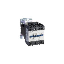
TeSys K contactor, 4 poles (2NO+2NC), for non-inductive load control applications up to 20A/690V AC-1. It provides a 48V DC coil, without built-in auxiliary contact, connection by screw clamp terminals. For operating rates until 600 cycles/hour and environments until 50°C, it procures reliability and durability to standard applications. Very compact (45mm width), DIN-rail mounting or screw fixing. Multi standards certified (IEC, UL, CSA, CCC, EAC), Green Premium compliant (RoHS/REACh).
Main
| Characteristic | Value(s) |
|---|---|
| Range | TeSys |
| Product or Component Type | Contactor |
| Device short name | LP1K |
| Contactor application | Resistive load |
Complementary
| Characteristic | Value(s) |
|---|---|
| Utilisation category | AC-1 |
| Poles description | 4P |
| power pole contact composition | 2 NO + 2 NC |
| [Ue] rated operational voltage | Power circuit <= 690 V AC <= 400 Hz Signalling circuit <= 690 V AC <= 400 Hz |
| [Ie] rated operational current | 20 A (at <140 °F (60 °C)) at <= 690 V AC AC-1 for power circuit |
| Control circuit type | DC standard |
| [Uc] control circuit voltage | 48 V DC |
| [Uimp] rated impulse withstand voltage | 8 kV |
| Overvoltage category | III |
| [Ith] conventional free air thermal current | 20 A (at 140 °F (60 °C)) for power circuit 10 A (at 122 °F (50 °C)) for signalling circuit |
| Irms rated making capacity | 110 A AC for power circuit conforming to IEC 60947 |
| Rated breaking capacity | 110 A at 220...230 V conforming to IEC 60947 110 A at 380...400 V conforming to IEC 60947 110 A at 415 V conforming to IEC 60947 110 A at 440 V conforming to IEC 60947 80 A at 500 V conforming to IEC 60947 70 A at 660...690 V conforming to IEC 60947 |
| [Icw] rated short-time withstand current | 90 A 122 °F (50 °C) - 1 s for power circuit 85 A 122 °F (50 °C) - 5 s for power circuit 80 A 122 °F (50 °C) - 10 s for power circuit 60 A 122 °F (50 °C) - 30 s for power circuit 45 A 122 °F (50 °C) - 1 min for power circuit 40 A 122 °F (50 °C) - 3 min for power circuit 20 A 122 °F (50 °C) - >= 15 min for power circuit |
| Associated fuse rating | 25 A gG at <= 440 V for power circuit 25 A aM for power circuit |
| Average impedance | 3 mOhm - Ith 20 A 50 Hz for power circuit |
| [Ui] rated insulation voltage | Power circuit 600 V UL 508 Power circuit 690 V IEC 60947-4-1 Power circuit 600 V CSA C22.2 No 14 |
| Inrush power in W | 3 W 68 °F (20 °C)) |
| Hold-in power consumption in W | 3 W 68 °F (20 °C) |
| Heat dissipation | 1.3 W |
| Control circuit voltage limits | Operational: 0.8...1.15 Uc (at <122 °F (50 °C)) Drop-out: >= 0.10 Uc (at <122 °F (50 °C)) |
| Connections - terminals | screw clamp terminals 1 0.002â¦0.006 in² (1.5â¦4 mm²)solid screw clamp terminals 1 0.001â¦0.006 in² (0.75â¦4 mm²)flexible without cable end screw clamp terminals 1 0.0005â¦0.004 in² (0.34â¦2.5 mm²)flexible with cable end screw clamp terminals 2 0.002â¦0.006 in² (1.5â¦4 mm²)solid screw clamp terminals 2 0.001â¦0.006 in² (0.75â¦4 mm²)flexible without cable end screw clamp terminals 2 0.0005â¦0.002 in² (0.34â¦1.5 mm²)flexible with cable end Power circuit screw clamp terminals 2 0.002 in² (1.5 mm²)flexible with cable end |
| Maximum operating rate | 3600 cyc/h |
| Mounting Support | Plate Rail |
| Tightening torque | 7.08â¦11.5 lbf.in (0.8â¦1.3 N.m) screw clamp terminals Philips No 2 7.08â¦11.5 lbf.in (0.8â¦1.3 N.m) screw clamp terminals flat à 6 mm 7.08â¦11.5 lbf.in (0.8â¦1.3 N.m) screw clamp terminals pozidriv No 2 |
| Operating time | 30...40 ms coil energisation and NO closing 10 ms coil de-energisation and NO opening 25...35 ms coil energisation and NC opening 15 ms coil de-energisation and NC closing |
| Safety reliability level | B10d = 1369863 cycles contactor with nominal load EN/ISO 13849-1 B10d = 20000000 cycles contactor with mechanical load EN/ISO 13849-1 |
| Mechanical durability | 10 Mcycles |
| Electrical durability | 0.16 Mcycles 20 A AC-1 <= 690 V |
| Height | 2.3 in (58 mm) |
| Width | 1.8 in (45 mm) |
| Depth | 2.2 in (57 mm) |
| Product Weight | 0.496 lb(US) (0.225 kg) |

TeSys K reversing contactor, 3 poles (3NO), for motor control applications up to 6A/690V AC-3 (2.2kW@400V). It provides 48V DC coils, 2NC built-in auxiliary contacts, connection by screw clamp terminals. For operating rates until 600 cycles/hour in AC-3 and environments until 50°C, it procures reliability and durability to standard applications. Compact (90mm width), DIN-rail mounting or screw fixing. With pre-wired reversing power connections, mechanical interlock (without electrical interlocking). Multi standards certified (IEC, UL, CSA, CCC, EAC), Green Premium compliant (RoHS/REACh).
Main
| Characteristic | Value(s) |
|---|---|
| Range | TeSys |
| product name | TeSys K |
| Product or Component Type | Reversing contactor |
| Device short name | LP2K |
| Device Application | Control |
| Contactor application | Motor control |
| Utilisation category | AC-3 AC-3e AC-4 |
| Device presentation | Preassembled with reversing power busbar |
| Poles description | 3P |
| power pole contact composition | 3 NO |
| [Ue] rated operational voltage | Power circuit 690 V AC 50/60 Hz Signalling circuit <= 690 V AC 50/60 Hz |
| [Ie] rated operational current | 6 A (at <140 °F (60 °C)) at <= 440 V AC AC-3 for power circuit 6 A (at <140 °F (60 °C)) at <= 440 V AC AC-3e for power circuit |
| Motor power kW | 1.5 kW 220...230 V AC 50/60 Hz 2.2 kW 380...415 V AC 50/60 Hz 3 kW 440/690 V AC 50/60 Hz |
| Control circuit type | DC standard |
| [Uc] control circuit voltage | 48 V DC |
| Auxiliary contact composition | 1 NC |
| [Uimp] rated impulse withstand voltage | 8 kV |
| Overvoltage category | III |
| [Ith] conventional free air thermal current | 20 A (at 140 °F (60 °C)) for power circuit 10 A (at 122 °F (50 °C)) for signalling circuit |
| Irms rated making capacity | 110 A AC for power circuit conforming to IEC 60947 110 A AC for signalling circuit conforming to IEC 60947 |
| Rated breaking capacity | 110 A at 220...230 V conforming to IEC 60947 110 A at 380...400 V conforming to IEC 60947 110 A at 415 V conforming to IEC 60947 110 A at 440 V conforming to IEC 60947 80 A at 500 V conforming to IEC 60947 70 A at 660...690 V conforming to IEC 60947 |
| [Icw] rated short-time withstand current | 90 A 122 °F (50 °C) - 1 s for power circuit 85 A 122 °F (50 °C) - 5 s for power circuit 80 A 122 °F (50 °C) - 10 s for power circuit 60 A 122 °F (50 °C) - 30 s for power circuit 45 A 122 °F (50 °C) - 1 min for power circuit 40 A 122 °F (50 °C) - 3 min for power circuit 20 A 122 °F (50 °C) - >= 15 min for power circuit 80 A - 1 s for signalling circuit 90 A - 500 ms for signalling circuit 110 A - 100 ms for signalling circuit |
| Associated fuse rating | 25 A gG at <= 440 V for power circuit 25 A aM for power circuit 10 A gG for signalling circuit conforming to IEC 60947 10 A gG for signalling circuit conforming to VDE 0660 |
| Average impedance | 3 mOhm - Ith 20 A 50 Hz for power circuit |
| [Ui] rated insulation voltage | Power circuit 600 V UL 508 Power circuit 690 V IEC 60947-4-1 Signalling circuit 690 V IEC 60947-4-1 Signalling circuit 690 V IEC 60947-5-1 Signalling circuit 600 V UL 508 Power circuit 600 V CSA C22.2 No 14 Signalling circuit 600 V CSA C22.2 No 14 |
| Electrical durability | 1.3 Mcycles 6 A AC-3 <= 440 V 1.3 Mcycles 6 A AC-3e <= 440 V 0.05 Mcycles 36 A AC-4 <= 440 V |
| Interlocking type | Mechanical |
| Mounting Support | Plate Rail |
| Standards | EN/IEC 60947-4-1 GB/T 14048.4 UL 60947-4-1 CSA C22.2 No 60947-4-1 JIS C8201-4-1 |
| Product Certifications | CB Scheme CCC UL CSA EAC CE UKCA |
| Connections - terminals | screw clamp terminals 1 0.002â¦0.006 in² (1.5â¦4 mm²)solid screw clamp terminals 1 0.001â¦0.006 in² (0.75â¦4 mm²)flexible without cable end screw clamp terminals 1 0.0005â¦0.004 in² (0.34â¦2.5 mm²)flexible with cable end screw clamp terminals 2 0.002â¦0.006 in² (1.5â¦4 mm²)solid screw clamp terminals 2 0.001â¦0.006 in² (0.75â¦4 mm²)flexible without cable end screw clamp terminals 2 0.0005â¦0.002 in² (0.34â¦1.5 mm²)flexible with cable end |
| Tightening torque | 7.08â¦11.5 lbf.in (0.8â¦1.3 N.m) screw clamp terminals Philips No 2 7.08â¦11.5 lbf.in (0.8â¦1.3 N.m) screw clamp terminals flat à 6 mm 7.08â¦11.5 lbf.in (0.8â¦1.3 N.m) screw clamp terminals pozidriv No 2 |
| Operating time | 30...40 ms coil energisation and NO closing 10 ms coil de-energisation and NO opening |
| Safety reliability level | B10d = 1369863 cycles contactor with nominal load EN/ISO 13849-1 B10d = 20000000 cycles contactor with mechanical load EN/ISO 13849-1 |
| Mechanical durability | 5 Mcycles |
| Maximum operating rate | 3600 cyc/h |
Complementary
| Characteristic | Value(s) |
|---|---|
| Control circuit voltage limits | Operational: 0.8...1.15 Uc (at <122 °F (50 °C)) Drop-out: 0.1...0.75 Uc (at <122 °F (50 °C)) |
| Inrush power in W | 3 W 68 °F (20 °C)) |
| Hold-in power consumption in W | 3 W 68 °F (20 °C) |
| Heat dissipation | 3 W |
| Auxiliary contacts type | Instantaneous 1 NC |
| Minimum switching current | 5 mA for signalling circuit |
| Minimum switching voltage | 17 V for signalling circuit |
| Non overlap distance | 0.02 in (0.5 mm) |
| Insulation resistance | > 10 MOhm for signalling circuit |
TeSys K contactor - 3P - AC-3 <= 440 V 9 A - 1 NC aux. - 12 V DC coil
TeSys K contactor - 3P - AC-3 <= 440 V 9 A - 1 NC aux. - 24 V DC coil

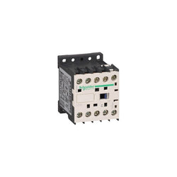
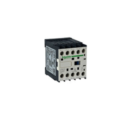
TeSys K contactor, 3 poles (3NO), for motor control applications up to 9A/690V AC-3 (4kW@400V). It provides a low consumption 24V DC coil with transient suppressor module, 1NC built-in auxiliary contact, connection by solder pins for printed circuit boards. For operating rates until 600 cycles/hour in AC-3 and environments until 50°C, it procures reliability and durability to standard applications. Very compact (45mm width), DIN-rail mounting or screw fixing. Multi standards certified (IEC, UL, CSA, CCC, EAC).
Main
| Characteristic | Value(s) |
|---|---|
| Range | TeSys |
| Product or Component Type | Contactor |
| Device short name | LP4K |
| Contactor application | Resistive load Motor control |
Complementary
| Characteristic | Value(s) |
|---|---|
| Utilisation category | AC-3 AC-3e AC-1 AC-4 |
| Poles description | 3P |
| power pole contact composition | 3 NO |
| [Ue] rated operational voltage | Power circuit <= 690 V AC <= 400 Hz Signalling circuit <= 690 V AC <= 400 Hz |
| [Ie] rated operational current | 9 A (at <140 °F (60 °C)) at <= 440 V AC AC-3 for power circuit 9 A (at <140 °F (60 °C)) at <= 440 V AC AC-3e for power circuit 20 A (at <140 °F (60 °C)) at <= 690 V AC AC-1 for power circuit |
| Control circuit type | DC wide range |
| [Uc] control circuit voltage | 24 V DC |
| Motor power kW | 2.2 kW 220...230 V AC 50/60 Hz AC-3 4 kW 380...415 V AC 50/60 Hz AC-3 4 kW 440/690 V AC 50/60 Hz AC-3 2.2 kW 220...230 V AC 50/60 Hz AC-3e 4 kW 380...415 V AC 50/60 Hz AC-3e 4 kW 440/690 V AC 50/60 Hz AC-3e 2.2 kW 220...230 V AC 50/60 Hz AC-4 4 kW 380...415 V AC 50/60 Hz AC-4 4 kW 440/690 V AC 50/60 Hz AC-4 |
| Auxiliary contact composition | 1 NC |
| [Uimp] rated impulse withstand voltage | 8 kV |
| Overvoltage category | III |
| [Ith] conventional free air thermal current | 20 A (at 140 °F (60 °C)) for power circuit 10 A (at 122 °F (50 °C)) for signalling circuit |
| Irms rated making capacity | 110 A AC for power circuit conforming to IEC 60947 110 A AC for signalling circuit conforming to IEC 60947 |
| Rated breaking capacity | 110 A at 220...230 V conforming to IEC 60947 110 A at 380...400 V conforming to IEC 60947 110 A at 415 V conforming to IEC 60947 110 A at 440 V conforming to IEC 60947 80 A at 500 V conforming to IEC 60947 70 A at 660...690 V conforming to IEC 60947 |
| [Icw] rated short-time withstand current | 90 A 122 °F (50 °C) - 1 s for power circuit 85 A 122 °F (50 °C) - 5 s for power circuit 80 A 122 °F (50 °C) - 10 s for power circuit 60 A 122 °F (50 °C) - 30 s for power circuit 45 A 122 °F (50 °C) - 1 min for power circuit 40 A 122 °F (50 °C) - 3 min for power circuit 20 A 122 °F (50 °C) - >= 15 min for power circuit 80 A - 1 s for signalling circuit 90 A - 500 ms for signalling circuit 110 A - 100 ms for signalling circuit |
| Associated fuse rating | 25 A gG at <= 440 V for power circuit 25 A aM for power circuit 10 A gG for signalling circuit conforming to IEC 60947 10 A gG for signalling circuit conforming to VDE 0660 |
| Average impedance | 3 mOhm - Ith 20 A 50 Hz for power circuit |
| [Ui] rated insulation voltage | Power circuit 600 V UL 508 Power circuit 690 V IEC 60947-4-1 Signalling circuit 690 V IEC 60947-4-1 Signalling circuit 690 V IEC 60947-5-1 Signalling circuit 600 V UL 508 Power circuit 600 V CSA C22.2 No 14 Signalling circuit 600 V CSA C22.2 No 14 |
| Insulation resistance | > 10 MOhm for signalling circuit |
| Inrush power in W | 1.8 W 68 °F (20 °C)) |
| Hold-in power consumption in W | 1.8 W 68 °F (20 °C) |
| Heat dissipation | 1.8 W |
| Control circuit voltage limits | Operational: 0.7...1.3 Uc (at <122 °F (50 °C)) Drop-out: >= 0.10 Uc (at <122 °F (50 °C)) |
| Connections - terminals | solder pins 0.001 in (0.035 mm)) |
| Maximum operating rate | 3600 cyc/h |
| Coil technology | Built-in bidirectional peak limiting diode suppressor |
| Auxiliary contacts type | Instantaneous 1 NC |
| Minimum switching current | 5 mA for signalling circuit |
| Minimum switching voltage | 17 V for signalling circuit |
| Mounting Support | Printed circuit boards |
| Operating time | 10...20 ms coil de-energisation and NO opening 30...40 ms coil energisation and NO closing |
| Safety reliability level | B10d = 1369863 cycles contactor with nominal load EN/ISO 13849-1 B10d = 20000000 cycles contactor with mechanical load EN/ISO 13849-1 |
| Mechanical durability | 30 Mcycles |
| Electrical durability | 1.3 Mcycles 9 A AC-3 <= 440 V 1.3 Mcycles 9 A AC-3e <= 440 V 0.16 Mcycles 20 A AC-1 <= 690 V 0.02 Mcycles 54 A AC-4 <= 440 V |
| Height | 2.3 in (58 mm) |
| Width | 1.8 in (45 mm) |
| Depth | 2.2 in (57 mm) |
| Product Weight | 0.518 lb(US) (0.235 kg) |

TeSys K contactor - 3P - AC-3 <= 440 V 9 A - 1 NO aux. - 48 V DC coil

TeSys K reversing contactor - 3P - AC-3 <= 440 V 6 A - 1 NC - 24 V DC coil

TeSys K contactor - 4P (4 NO) - AC-1 <= 440 V 20 A - 110 V DC coil

TeSys K contactor - 4P (2 NO + 2 NC) - AC-1 <= 440 V 20 A - 110 V DC coil

TeSys K reversing contactor, 3 poles (3NO), for motor control applications up to 9A/690V AC-3 (4kW@400V). It provides 24V DC coil with transient suppressor module, 2NC built-in auxiliary contacts, connection by screw clamp terminals. For operating rates until 600 cycles/hour in AC-3 and environments until 50°C, it procures reliability and durability to standard applications. Compact (90mm width), DIN-rail mounting or screw fixing. With pre-wired reversing power connections, mechanical interlock (without electrical interlocking). Multi standards certified (IEC, UL, CSA, CCC, EAC).
Main
| Characteristic | Value(s) |
|---|---|
| Range | TeSys |
| product name | TeSys K |
| Product or Component Type | Reversing contactor |
| Device short name | LP2K |
| Device Application | Control |
| Contactor application | Motor control Resistive load |
| Utilisation category | AC-3 AC-3e AC-4 AC-1 |
| Device presentation | Preassembled with reversing power busbar |
| Poles description | 3P |
| power pole contact composition | 3 NO |
| [Ue] rated operational voltage | Power circuit 690 V AC 50/60 Hz Signalling circuit <= 690 V AC 50/60 Hz |
| [Ie] rated operational current | 9 A (at <140 °F (60 °C)) at <= 440 V AC AC-3 for power circuit 9 A (at <140 °F (60 °C)) at <= 440 V AC AC-3e for power circuit 20 A (at <140 °F (60 °C)) at <= 690 V AC AC-1 for power circuit |
| Motor power kW | 2.2 kW 220...230 V AC 50/60 Hz 4 kW 380...415 V AC 50/60 Hz 4 kW 440/690 V AC 50/60 Hz |
| Control circuit type | DC standard |
| [Uc] control circuit voltage | 24 V DC |
| Auxiliary contact composition | 1 NC |
| [Uimp] rated impulse withstand voltage | 8 kV |
| Overvoltage category | III |
| [Ith] conventional free air thermal current | 20 A (at 140 °F (60 °C)) for power circuit 10 A (at 122 °F (50 °C)) for signalling circuit |
| Irms rated making capacity | 110 A AC for power circuit conforming to IEC 60947 110 A AC for signalling circuit conforming to IEC 60947 |
| Rated breaking capacity | 110 A at 220...230 V conforming to IEC 60947 110 A at 380...400 V conforming to IEC 60947 110 A at 415 V conforming to IEC 60947 110 A at 440 V conforming to IEC 60947 80 A at 500 V conforming to IEC 60947 70 A at 660...690 V conforming to IEC 60947 |
| [Icw] rated short-time withstand current | 90 A 122 °F (50 °C) - 1 s for power circuit 85 A 122 °F (50 °C) - 5 s for power circuit 80 A 122 °F (50 °C) - 10 s for power circuit 60 A 122 °F (50 °C) - 30 s for power circuit 45 A 122 °F (50 °C) - 1 min for power circuit 40 A 122 °F (50 °C) - 3 min for power circuit 20 A 122 °F (50 °C) - >= 15 min for power circuit 80 A - 1 s for signalling circuit 90 A - 500 ms for signalling circuit 110 A - 100 ms for signalling circuit |
| Associated fuse rating | 25 A gG at <= 440 V for power circuit 25 A aM for power circuit 10 A gG for signalling circuit conforming to IEC 60947 10 A gG for signalling circuit conforming to VDE 0660 |
| Average impedance | 3 mOhm - Ith 20 A 50 Hz for power circuit |
| [Ui] rated insulation voltage | Power circuit 600 V UL 508 Power circuit 690 V IEC 60947-4-1 Signalling circuit 690 V IEC 60947-4-1 Signalling circuit 690 V IEC 60947-5-1 Signalling circuit 600 V UL 508 Power circuit 600 V CSA C22.2 No 14 Signalling circuit 600 V CSA C22.2 No 14 |
| Electrical durability | 1.3 Mcycles 9 A AC-3 <= 440 V 1.3 Mcycles 9 A AC-3e <= 440 V 0.16 Mcycles 20 A AC-1 <= 690 V 0.02 Mcycles 54 A AC-4 <= 440 V |
| Interlocking type | Mechanical |
| Mounting Support | Plate Rail |
| Standards | EN/IEC 60947-4-1 GB/T 14048.4 UL 60947-4-1 CSA C22.2 No 60947-4-1 JIS C8201-4-1 |
| Product Certifications | CB Scheme CCC UL CSA EAC CE UKCA |
| Connections - terminals | screw clamp terminals 1 0.002â¦0.006 in² (1.5â¦4 mm²)solid screw clamp terminals 1 0.001â¦0.006 in² (0.75â¦4 mm²)flexible without cable end screw clamp terminals 1 0.0005â¦0.004 in² (0.34â¦2.5 mm²)flexible with cable end screw clamp terminals 2 0.002â¦0.006 in² (1.5â¦4 mm²)solid screw clamp terminals 2 0.001â¦0.006 in² (0.75â¦4 mm²)flexible without cable end screw clamp terminals 2 0.0005â¦0.002 in² (0.34â¦1.5 mm²)flexible with cable end |
| Tightening torque | 7.08â¦11.5 lbf.in (0.8â¦1.3 N.m) screw clamp terminals Philips No 2 7.08â¦11.5 lbf.in (0.8â¦1.3 N.m) screw clamp terminals flat à 6 mm 7.08â¦11.5 lbf.in (0.8â¦1.3 N.m) screw clamp terminals pozidriv No 2 |
| Operating time | 30...40 ms coil energisation and NO closing 10 ms coil de-energisation and NO opening |
| Safety reliability level | B10d = 1369863 cycles contactor with nominal load EN/ISO 13849-1 B10d = 20000000 cycles contactor with mechanical load EN/ISO 13849-1 |
| Mechanical durability | 5 Mcycles |
| Maximum operating rate | 3600 cyc/h |
Complementary
| Characteristic | Value(s) |
|---|---|
| Coil technology | Built-in bidirectional peak limiting diode suppressor |
| Control circuit voltage limits | Operational: 0.8...1.15 Uc (at <122 °F (50 °C)) Drop-out: 0.1...0.75 Uc (at <122 °F (50 °C)) |
| Inrush power in W | 3 W 68 °F (20 °C)) |
| Hold-in power consumption in W | 3 W 68 °F (20 °C) |
| Heat dissipation | 3 W |
| Auxiliary contacts type | Instantaneous 1 NC |
| Minimum switching current | 5 mA for signalling circuit |
| Minimum switching voltage | 17 V for signalling circuit |
| Non overlap distance | 0.02 in (0.5 mm) |
| Insulation resistance | > 10 MOhm for signalling circuit |

TeSys K contactor, 3 poles (3NO), for motor control applications up to 12A/690V AC-3 (5.5kW@400V), and for non-inductive load control applications up to 20A/690V AC-1. It provides a 12V DC coil, 1NO built-in auxiliary contact, connection by screw clamp terminals. For operating rates until 600 cycles/hour and environments until 50°C, it procures reliability and durability to standard applications. Very compact (45mm width), DIN-rail mounting or screw fixing. Multi standards certified (IEC, UL, CSA, CCC, EAC).
Main
| Characteristic | Value(s) |
|---|---|
| Range | TeSys |
| Product or Component Type | Contactor |
| Device short name | LP1K |
| Contactor application | Motor control Resistive load |
Complementary
| Characteristic | Value(s) |
|---|---|
| Utilisation category | AC-3 AC-3e AC-1 AC-4 |
| Poles description | 3P |
| power pole contact composition | 3 NO |
| [Ue] rated operational voltage | Power circuit <= 690 V AC <= 400 Hz Signalling circuit <= 690 V AC <= 400 Hz |
| [Ie] rated operational current | 12 A (at <140 °F (60 °C)) at <= 440 V AC AC-3 for power circuit 12 A (at <140 °F (60 °C)) at <= 440 V AC AC-3e for power circuit 20 A (at <140 °F (60 °C)) at <= 690 V AC AC-1 for power circuit |
| Control circuit type | DC standard |
| [Uc] control circuit voltage | 12 V DC |
| Motor power kW | 3 kW 220...230 V AC 50/60 Hz AC-3 5.5 kW 380...415 V AC 50/60 Hz AC-3 5.5 kW 440 V AC 50/60 Hz AC-3 4 kW 690 V AC 50/60 Hz AC-3 3 kW 220...230 V AC 50/60 Hz AC-3e 5.5 kW 380...415 V AC 50/60 Hz AC-3e 5.5 kW 440 V AC 50/60 Hz AC-3e 4 kW 690 V AC 50/60 Hz AC-3e 3 kW 220...230 V AC 50/60 Hz AC-4 5.5 kW 380...415 V AC 50/60 Hz AC-4 5.5 kW 440 V AC 50/60 Hz AC-4 |
| Auxiliary contact composition | 1 NO |
| [Uimp] rated impulse withstand voltage | 8 kV |
| Overvoltage category | III |
| [Ith] conventional free air thermal current | 20 A (at 140 °F (60 °C)) for power circuit 10 A (at 122 °F (50 °C)) for signalling circuit |
| Irms rated making capacity | 144 A AC for power circuit conforming to IEC 60947 110 A AC for signalling circuit conforming to IEC 60947 |
| Rated breaking capacity | 110 A at 440 V conforming to IEC 60947 80 A at 500 V conforming to IEC 60947 70 A at 660...690 V conforming to IEC 60947 |
| [Icw] rated short-time withstand current | 115 A 122 °F (50 °C) - 1 s for power circuit 105 A 122 °F (50 °C) - 5 s for power circuit 100 A 122 °F (50 °C) - 10 s for power circuit 75 A 122 °F (50 °C) - 30 s for power circuit 55 A 122 °F (50 °C) - 1 min for power circuit 50 A 122 °F (50 °C) - 3 min for power circuit 25 A 122 °F (50 °C) - >= 15 min for power circuit 80 A - 1 s for signalling circuit 90 A - 500 ms for signalling circuit 110 A - 100 ms for signalling circuit |
| Associated fuse rating | 25 A gG at <= 440 V for power circuit 25 A aM for power circuit 10 A gG for signalling circuit conforming to IEC 60947 10 A gG for signalling circuit conforming to VDE 0660 |
| Average impedance | 3 mOhm - Ith 20 A 50 Hz for power circuit |
| [Ui] rated insulation voltage | Power circuit 600 V UL 508 Power circuit 690 V IEC 60947-4-1 Signalling circuit 690 V IEC 60947-4-1 Signalling circuit 690 V IEC 60947-5-1 Signalling circuit 600 V UL 508 Power circuit 600 V CSA C22.2 No 14 Signalling circuit 600 V CSA C22.2 No 14 |
| Insulation resistance | > 10 MOhm for signalling circuit |
| Inrush power in W | 3 W 68 °F (20 °C)) |
| Hold-in power consumption in W | 3 W 68 °F (20 °C) |
| Heat dissipation | 1.3 W |
| Control circuit voltage limits | Operational: 0.8...1.15 Uc (at <122 °F (50 °C)) Drop-out: >= 0.10 Uc (at <122 °F (50 °C)) |
| Connections - terminals | screw clamp terminals 1 0.002â¦0.006 in² (1.5â¦4 mm²)solid screw clamp terminals 1 0.001â¦0.006 in² (0.75â¦4 mm²)flexible without cable end screw clamp terminals 1 0.0005â¦0.004 in² (0.34â¦2.5 mm²)flexible with cable end screw clamp terminals 2 0.002â¦0.006 in² (1.5â¦4 mm²)solid screw clamp terminals 2 0.001â¦0.006 in² (0.75â¦4 mm²)flexible without cable end screw clamp terminals 2 0.0005â¦0.002 in² (0.34â¦1.5 mm²)flexible with cable end Power circuit screw clamp terminals 2 0.002 in² (1.5 mm²)flexible with cable end |
| Maximum operating rate | 3600 cyc/h |
| Auxiliary contacts type | Instantaneous 1 NO |
| Minimum switching current | 5 mA for signalling circuit |
| Minimum switching voltage | 17 V for signalling circuit |
| Mounting Support | Rail Plate |
| Tightening torque | 7.08â¦11.5 lbf.in (0.8â¦1.3 N.m) screw clamp terminals Philips No 2 7.08â¦11.5 lbf.in (0.8â¦1.3 N.m) screw clamp terminals flat à 6 mm 7.08â¦11.5 lbf.in (0.8â¦1.3 N.m) screw clamp terminals pozidriv No 2 |
| Operating time | 30...40 ms coil energisation and NO closing 10 ms coil de-energisation and NO opening |
| Safety reliability level | B10d = 1369863 cycles contactor with nominal load EN/ISO 13849-1 B10d = 20000000 cycles contactor with mechanical load EN/ISO 13849-1 |
| Mechanical durability | 10 Mcycles |
| Electrical durability | 1.3 Mcycles 12 A AC-3 <= 440 V 1.3 Mcycles 12 A AC-3e <= 440 V 0.3 Mcycles 20 A AC-1 <= 690 V 0.02 Mcycles 72 A AC-4 <= 440 V |
| Height | 2.3 in (58 mm) |
| Width | 1.8 in (45 mm) |
| Depth | 2.2 in (57 mm) |
| Product Weight | 0.496 lb(US) (0.225 kg) |
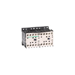
TeSys K reversing contactor, 3 poles (3NO), for motor control applications up to 12A/690V AC-3 (5.5kW@400V). It provides low consumption 24V DC coils with transient suppressor module, 2NC built-in auxiliary contacts, connection by screw clamp terminals. For operating rates until 600 cycles/hour in AC-3 and environments until 50°C, it procures reliability and durability to standard applications. Compact (90mm width), DIN-rail mounting or screw fixing. With pre-wired reversing power connections, mechanical interlock (without electrical interlocking). Multi standards certified (IEC, UL, CSA, CCC, EAC).
Main
| Characteristic | Value(s) |
|---|---|
| Range | TeSys |
| product name | TeSys K |
| Product or Component Type | Reversing contactor |
| Device short name | LP5K |
| Device Application | Control |
| Contactor application | Motor control Resistive load |
| Utilisation category | AC-1 AC-3 AC-4 AC-3e |
| Device presentation | Preassembled with reversing power busbar |
| Poles description | 3P |
| power pole contact composition | 3 NO |
| [Ue] rated operational voltage | Power circuit 690 V AC 50/60 Hz Signalling circuit <= 690 V AC 50/60 Hz |
| [Ie] rated operational current | 20 A (at <122 °F (50 °C)) at <= 440 V AC AC-1 for power circuit 16 A (at <158 °F (70 °C)) at 690 V AC AC-1 for power circuit 12 A at <= 440 V AC AC-3 for power circuit 12 A at <= 440 V AC AC-3e for power circuit |
| Motor power kW | 4 kW 480 V AC 50/60 Hz 4 kW 500...600 V AC 50/60 Hz 4 kW 660...690 V AC 50/60 Hz 3 kW 220...230 V AC 50/60 Hz 5.5 kW 380...415 V AC 50/60 Hz 5.5 kW 440 V AC 50/60 Hz |
| Control circuit type | DC low consumption |
| [Uc] control circuit voltage | 24 V DC |
| Auxiliary contact composition | 1 NC |
| [Uimp] rated impulse withstand voltage | 8 kV |
| Overvoltage category | III |
| [Ith] conventional free air thermal current | 20 A (at 122 °F (50 °C)) for power circuit 10 A (at 122 °F (50 °C)) for signalling circuit |
| Irms rated making capacity | 110 A AC for signalling circuit conforming to IEC 60947 144 A AC for power circuit conforming to NF C 63-110 144 A AC for power circuit conforming to IEC 60947 |
| Rated breaking capacity | 110 A at 440 V conforming to IEC 60947 80 A at 500 V conforming to IEC 60947 70 A at 660...690 V conforming to IEC 60947 |
| [Icw] rated short-time withstand current | 115 A 122 °F (50 °C) - 1 s for power circuit 105 A 122 °F (50 °C) - 5 s for power circuit 100 A 122 °F (50 °C) - 10 s for power circuit 75 A 122 °F (50 °C) - 30 s for power circuit 55 A 122 °F (50 °C) - 1 min for power circuit 50 A 122 °F (50 °C) - 3 min for power circuit 80 A - 1 s for signalling circuit 90 A - 500 ms for signalling circuit 110 A - 100 ms for signalling circuit 25 A 122 °F (50 °C) - >= 15 min for power circuit |
| Associated fuse rating | 25 A gG at <= 440 V for power circuit 25 A aM for power circuit 10 A gG for signalling circuit conforming to IEC 60947 10 A gG for signalling circuit conforming to VDE 0660 |
| Average impedance | 3 mOhm - Ith 20 A 50 Hz for power circuit |
| [Ui] rated insulation voltage | Power circuit 600 V UL 508 Power circuit 690 V IEC 60947-4-1 Signalling circuit 690 V IEC 60947-4-1 Signalling circuit 690 V IEC 60947-5-1 Signalling circuit 600 V UL 508 Power circuit 600 V CSA C22.2 No 14 Signalling circuit 600 V CSA C22.2 No 14 |
| Electrical durability | 1.3 Mcycles 12 A AC-3 <= 440 V 1.3 Mcycles 12 A AC-3e <= 440 V 0.3 Mcycles 20 A AC-1 <= 690 V 0.02 Mcycles 72 A AC-4 <= 440 V |
| Interlocking type | Mechanical |
| Mounting Support | Rail Plate |
| Standards | EN/IEC 60947-4-1 GB/T 14048.4 UL 60947-4-1 CSA C22.2 No 60947-4-1 JIS C8201-4-1 |
| Product Certifications | CB Scheme CCC UL CSA EAC CE UKCA |
| Connections - terminals | screw clamp terminals 1 0.002â¦0.006 in² (1.5â¦4 mm²)solid screw clamp terminals 1 0.001â¦0.006 in² (0.75â¦4 mm²)flexible without cable end screw clamp terminals 1 0.0005â¦0.004 in² (0.34â¦2.5 mm²)flexible with cable end screw clamp terminals 2 0.002â¦0.006 in² (1.5â¦4 mm²)solid screw clamp terminals 2 0.001â¦0.006 in² (0.75â¦4 mm²)flexible without cable end screw clamp terminals 2 0.0005â¦0.002 in² (0.34â¦1.5 mm²)flexible with cable end |
| Tightening torque | 7.08â¦11.5 lbf.in (0.8â¦1.3 N.m) screw clamp terminals Philips No 2 7.08â¦11.5 lbf.in (0.8â¦1.3 N.m) screw clamp terminals flat à 6 mm 7.08â¦11.5 lbf.in (0.8â¦1.3 N.m) screw clamp terminals pozidriv No 2 |
| Operating time | 10...20 ms coil de-energisation and NO opening 30...40 ms coil energisation and NO closing |
| Safety reliability level | B10d = 1369863 cycles contactor with nominal load EN/ISO 13849-1 B10d = 20000000 cycles contactor with mechanical load EN/ISO 13849-1 |
| Mechanical durability | 5 Mcycles |
| Maximum operating rate | 3600 cyc/h |
Complementary
| Characteristic | Value(s) |
|---|---|
| Coil technology | Built-in bidirectional peak limiting diode suppressor |
| Control circuit voltage limits | Operational: 0.7...1.30 Uc (at <122 °F (50 °C)) Drop-out: 0.1...0.7 Uc (at <122 °F (50 °C)) |
| Inrush power in W | 1.8 W 68 °F (20 °C)) |
| Hold-in power consumption in W | 1.8 W 68 °F (20 °C) |
| Heat dissipation | 1.8 W |
| Auxiliary contacts type | Instantaneous 1 NC |
| Minimum switching current | 5 mA for signalling circuit |
| Minimum switching voltage | 17 V for signalling circuit |
| Non overlap distance | 0.02 in (0.5 mm) |
| Insulation resistance | > 10 MOhm for signalling circuit |
TeSys K contactor - 3P - AC-3 <= 440 V 9 A - 1 NO aux. - 24 V DC coil

LP2K0910BD is a compact 3-pole TeSys K reversing contactor from Schneider Electric for motor applications. Rated 9A AC-3 4kW@400V, it includes a 24V DC coil, 1NO auxiliary contact, a mechanical interlock and a pre-wired reversing circuit. LP2K0910BD is a 3-pole TeSys K reversing contactor from Schneider Electric for simple motor applications rated up to 4kW@400V. Very compact, DIN-rail compatible, it is assembled with a mechanical interlock and a pre-wired reversing circuit. It can be easily integrated into all control systems thanks to its 24V DC coil and 1NO built-in auxiliary contact. Available worldwide, it complies with multi-standards (IEC, UL, CSA, CCC, EAC, Marine). Very compact, 90mm wide, for DIN-rail and panel mounting. Assembled with mechanical interlock and pre-wired reversing circuit. Ready for connection to all control systems thanks to a 24V DC control voltage and 2NO built-in auxiliary contact. Can be completed with auxiliary contact blocks (LA1K, LA2K) and thermal relays (LR2K).
Main
| Characteristic | Value(s) |
|---|---|
| Range | TeSys |
| product name | TeSys K |
| Product or Component Type | Reversing contactor |
| Device short name | LP2K |
| Device Application | Control |
| Contactor application | Resistive load Motor control |
| Utilisation category | AC-3 AC-3e AC-4 AC-1 |
| Device presentation | Preassembled with reversing power busbar |
| Poles description | 3P |
| power pole contact composition | 3 NO |
| [Ue] rated operational voltage | Power circuit 690 V AC 50/60 Hz Signalling circuit <= 690 V AC 50/60 Hz |
| [Ie] rated operational current | 9 A (at <140 °F (60 °C)) at <= 440 V AC AC-3 for power circuit 9 A (at <140 °F (60 °C)) at <= 440 V AC AC-3e for power circuit 20 A (at <140 °F (60 °C)) at <= 690 V AC AC-1 for power circuit |
| Motor power kW | 2.2 kW 220...230 V AC 50/60 Hz 4 kW 380...415 V AC 50/60 Hz 4 kW 440/690 V AC 50/60 Hz |
| Control circuit type | DC standard |
| [Uc] control circuit voltage | 24 V DC |
| Auxiliary contact composition | 1 NO |
| [Uimp] rated impulse withstand voltage | 8 kV |
| Overvoltage category | III |
| [Ith] conventional free air thermal current | 20 A (at 140 °F (60 °C)) for power circuit 10 A (at 122 °F (50 °C)) for signalling circuit |
| Irms rated making capacity | 110 A AC for power circuit conforming to IEC 60947 110 A AC for signalling circuit conforming to IEC 60947 |
| Rated breaking capacity | 110 A at 220...230 V conforming to IEC 60947 110 A at 380...400 V conforming to IEC 60947 110 A at 415 V conforming to IEC 60947 110 A at 440 V conforming to IEC 60947 80 A at 500 V conforming to IEC 60947 70 A at 660...690 V conforming to IEC 60947 |
| [Icw] rated short-time withstand current | 90 A 122 °F (50 °C) - 1 s for power circuit 85 A 122 °F (50 °C) - 5 s for power circuit 80 A 122 °F (50 °C) - 10 s for power circuit 60 A 122 °F (50 °C) - 30 s for power circuit 45 A 122 °F (50 °C) - 1 min for power circuit 40 A 122 °F (50 °C) - 3 min for power circuit 20 A 122 °F (50 °C) - >= 15 min for power circuit 80 A - 1 s for signalling circuit 90 A - 500 ms for signalling circuit 110 A - 100 ms for signalling circuit |
| Associated fuse rating | 25 A gG at <= 440 V for power circuit 25 A aM for power circuit 10 A gG for signalling circuit conforming to IEC 60947 10 A gG for signalling circuit conforming to VDE 0660 |
| Average impedance | 3 mOhm - Ith 20 A 50 Hz for power circuit |
| [Ui] rated insulation voltage | Power circuit 600 V UL 508 Power circuit 690 V IEC 60947-4-1 Signalling circuit 690 V IEC 60947-4-1 Signalling circuit 690 V IEC 60947-5-1 Signalling circuit 600 V UL 508 Power circuit 600 V CSA C22.2 No 14 Signalling circuit 600 V CSA C22.2 No 14 |
| Electrical durability | 1.3 Mcycles 9 A AC-3 <= 440 V 1.3 Mcycles 9 A AC-3e <= 440 V 0.16 Mcycles 20 A AC-1 <= 690 V 0.02 Mcycles 54 A AC-4 <= 440 V |
| Interlocking type | Mechanical |
| Mounting Support | Plate Rail |
| Standards | EN/IEC 60947-4-1 GB/T 14048.4 UL 60947-4-1 CSA C22.2 No 60947-4-1 JIS C8201-4-1 |
| Product Certifications | CB Scheme CCC UL CSA EAC CE UKCA |
| Connections - terminals | screw clamp terminals 1 0.002â¦0.006 in² (1.5â¦4 mm²)solid screw clamp terminals 1 0.001â¦0.006 in² (0.75â¦4 mm²)flexible without cable end screw clamp terminals 1 0.0005â¦0.004 in² (0.34â¦2.5 mm²)flexible with cable end screw clamp terminals 2 0.002â¦0.006 in² (1.5â¦4 mm²)solid screw clamp terminals 2 0.001â¦0.006 in² (0.75â¦4 mm²)flexible without cable end screw clamp terminals 2 0.0005â¦0.002 in² (0.34â¦1.5 mm²)flexible with cable end |
| Tightening torque | 7.08â¦11.5 lbf.in (0.8â¦1.3 N.m) screw clamp terminals Philips No 2 7.08â¦11.5 lbf.in (0.8â¦1.3 N.m) screw clamp terminals flat à 6 mm 7.08â¦11.5 lbf.in (0.8â¦1.3 N.m) screw clamp terminals pozidriv No 2 |
| Operating time | 30...40 ms coil energisation and NO closing 10 ms coil de-energisation and NO opening |
| Safety reliability level | B10d = 1369863 cycles contactor with nominal load EN/ISO 13849-1 B10d = 20000000 cycles contactor with mechanical load EN/ISO 13849-1 |
| Mechanical durability | 5 Mcycles |
| Maximum operating rate | 3600 cyc/h |
Complementary
| Characteristic | Value(s) |
|---|---|
| Control circuit voltage limits | Operational: 0.8...1.15 Uc (at <122 °F (50 °C)) Drop-out: 0.1...0.75 Uc (at <122 °F (50 °C)) |
| Inrush power in W | 3 W 68 °F (20 °C)) |
| Hold-in power consumption in W | 3 W 68 °F (20 °C) |
| Heat dissipation | 3 W |
| Auxiliary contacts type | Instantaneous 1 NO |
| Minimum switching current | 5 mA for signalling circuit |
| Minimum switching voltage | 17 V for signalling circuit |
| Non overlap distance | 0.02 in (0.5 mm) |
| Insulation resistance | > 10 MOhm for signalling circuit |

| Product | |
| Article Number (Market Facing Number) | 3RE19131CB1 |
| Product Description | Enclosure for DOL starter, Size S00 Contactor and relay mounting prepared PE terminal Molded-plastic enclosure IP65 Version for Europe Button black/white |
| Product family | Not available |
| Product Lifecycle (PLM) | PM500:Discontinued Product or end of PLM & Support |
| Additional Product Information | |
| EAN | 4011209567597 |
| UPC | Not available |
| Commodity Code | 85365080 |
| LKZ_FDB/ CatalogID | CC-IC10 |
| Product Group | 3729 |
| Group Code | R711 |
| Country of origin | Brazil |
| SCIP number | Not available |
| Delivery information | |
| Net Weight (lb) | 0.668 lb |
| Package size unit of measure | Inch |
| Packaging Quantity | 1 |
TeSys K contactor - 3P - AC-3 <= 440 V 6 A - 1 NO aux. - 12 V DC coil

TeSys K contactor, 3 poles (3NO), for motor control applications up to 12A/690V AC-3 (5.5kW@400V), and for non-inductive load control applications up to 20A/690V AC-1. It provides a 24V DC coil with transient suppressor module, 1NC built-in auxiliary contact, connection by screw clamp terminals. For operating rates until 600 cycles/hour and environments until 50°C, it procures reliability and durability to standard applications. Very compact (45mm width), DIN-rail mounting or screw fixing. Multi standards certified (IEC, UL, CSA, CCC, EAC).
Main
| Characteristic | Value(s) |
|---|---|
| Range | TeSys |
| Product or Component Type | Contactor |
| Device short name | LP1K |
| Contactor application | Motor control Resistive load |
Complementary
| Characteristic | Value(s) |
|---|---|
| Utilisation category | AC-3 AC-3e AC-1 AC-4 |
| Poles description | 3P |
| power pole contact composition | 3 NO |
| [Ue] rated operational voltage | Power circuit <= 690 V AC <= 400 Hz Signalling circuit <= 690 V AC <= 400 Hz |
| [Ie] rated operational current | 12 A (at <140 °F (60 °C)) at <= 440 V AC AC-3 for power circuit 12 A (at <140 °F (60 °C)) at <= 440 V AC AC-3e for power circuit 20 A (at <140 °F (60 °C)) at <= 690 V AC AC-1 for power circuit |
| Control circuit type | DC standard |
| [Uc] control circuit voltage | 24 V DC |
| Motor power kW | 3 kW 220...230 V AC 50/60 Hz AC-3 5.5 kW 380...415 V AC 50/60 Hz AC-3 5.5 kW 440 V AC 50/60 Hz AC-3 4 kW 690 V AC 50/60 Hz AC-3 3 kW 220...230 V AC 50/60 Hz AC-3e 5.5 kW 380...415 V AC 50/60 Hz AC-3e 5.5 kW 440 V AC 50/60 Hz AC-3e 4 kW 690 V AC 50/60 Hz AC-3e 3 kW 220...230 V AC 50/60 Hz AC-4 5.5 kW 380...415 V AC 50/60 Hz AC-4 5.5 kW 440 V AC 50/60 Hz AC-4 4 kW 690 V AC 50/60 Hz AC-4 |
| Auxiliary contact composition | 1 NC |
| [Uimp] rated impulse withstand voltage | 8 kV |
| Overvoltage category | III |
| [Ith] conventional free air thermal current | 20 A (at 140 °F (60 °C)) for power circuit 10 A (at 122 °F (50 °C)) for signalling circuit |
| Irms rated making capacity | 144 A AC for power circuit conforming to IEC 60947 110 A AC for signalling circuit conforming to IEC 60947 |
| Rated breaking capacity | 110 A at 440 V conforming to IEC 60947 80 A at 500 V conforming to IEC 60947 70 A at 660...690 V conforming to IEC 60947 |
| [Icw] rated short-time withstand current | 115 A 122 °F (50 °C) - 1 s for power circuit 105 A 122 °F (50 °C) - 5 s for power circuit 100 A 122 °F (50 °C) - 10 s for power circuit 75 A 122 °F (50 °C) - 30 s for power circuit 55 A 122 °F (50 °C) - 1 min for power circuit 50 A 122 °F (50 °C) - 3 min for power circuit 25 A 122 °F (50 °C) - >= 15 min for power circuit 80 A - 1 s for signalling circuit 90 A - 500 ms for signalling circuit 110 A - 100 ms for signalling circuit |
| Associated fuse rating | 25 A gG at <= 440 V for power circuit 25 A aM for power circuit 10 A gG for signalling circuit conforming to IEC 60947 10 A gG for signalling circuit conforming to VDE 0660 |
| Average impedance | 3 mOhm - Ith 20 A 50 Hz for power circuit |
| [Ui] rated insulation voltage | Power circuit 600 V UL 508 Power circuit 690 V IEC 60947-4-1 Signalling circuit 690 V IEC 60947-4-1 Signalling circuit 690 V IEC 60947-5-1 Signalling circuit 600 V UL 508 Power circuit 600 V CSA C22.2 No 14 Signalling circuit 600 V CSA C22.2 No 14 |
| Insulation resistance | > 10 MOhm for signalling circuit |
| Inrush power in W | 3 W 68 °F (20 °C)) |
| Hold-in power consumption in W | 3 W 68 °F (20 °C) |
| Heat dissipation | 1.3 W |
| Control circuit voltage limits | Operational: 0.8...1.15 Uc (at <122 °F (50 °C)) Drop-out: >= 0.10 Uc (at <122 °F (50 °C)) |
| Connections - terminals | screw clamp terminals 1 0.002â¦0.006 in² (1.5â¦4 mm²)solid screw clamp terminals 1 0.001â¦0.006 in² (0.75â¦4 mm²)flexible without cable end screw clamp terminals 1 0.0005â¦0.004 in² (0.34â¦2.5 mm²)flexible with cable end screw clamp terminals 2 0.002â¦0.006 in² (1.5â¦4 mm²)solid screw clamp terminals 2 0.001â¦0.006 in² (0.75â¦4 mm²)flexible without cable end screw clamp terminals 2 0.0005â¦0.002 in² (0.34â¦1.5 mm²)flexible with cable end Power circuit screw clamp terminals 2 0.002 in² (1.5 mm²)flexible with cable end |
| Maximum operating rate | 3600 cyc/h |
| Coil technology | Built-in bidirectional peak limiting diode suppressor |
| Auxiliary contacts type | Instantaneous 1 NC |
| Minimum switching current | 5 mA for signalling circuit |
| Minimum switching voltage | 17 V for signalling circuit |
| Mounting Support | Plate Rail |
| Tightening torque | 7.08â¦11.5 lbf.in (0.8â¦1.3 N.m) screw clamp terminals Philips No 2 7.08â¦11.5 lbf.in (0.8â¦1.3 N.m) screw clamp terminals flat à 6 mm 7.08â¦11.5 lbf.in (0.8â¦1.3 N.m) screw clamp terminals pozidriv No 2 |
| Operating time | 30...40 ms coil energisation and NO closing 10 ms coil de-energisation and NO opening |
| Safety reliability level | B10d = 1369863 cycles contactor with nominal load EN/ISO 13849-1 B10d = 20000000 cycles contactor with mechanical load EN/ISO 13849-1 |
| Mechanical durability | 10 Mcycles |
| Electrical durability | 1.3 Mcycles 12 A AC-3 <= 440 V 1.3 Mcycles 12 A AC-3e <= 440 V 0.3 Mcycles 20 A AC-1 <= 690 V 0.02 Mcycles 72 A AC-4 <= 440 V |
| Height | 2.3 in (58 mm) |
| Width | 1.8 in (45 mm) |
| Depth | 2.2 in (57 mm) |
| Product Weight | 0.496 lb(US) (0.225 kg) |

TeSys K reversing contactor, 3 poles (3NO), for motor control applications up to 6A/690V AC-3 (2.2kW@400V). It provides low consumption 24V DC coils with transient suppressor module, 2NC built-in auxiliary contacts, connection by screw clamp terminals. For operating rates until 600 cycles/hour in AC-3 and environments until 50°C, it procures reliability and durability to standard applications. Compact (90mm width), DIN-rail mounting or screw fixing. With pre-wired reversing power connections, mechanical interlock (without electrical interlocking). Multi standards certified (IEC, UL, CSA, CCC, EAC).
Main
| Characteristic | Value(s) |
|---|---|
| Range | TeSys |
| product name | TeSys K |
| Product or Component Type | Reversing contactor |
| Device short name | LP5K |
| Device Application | Control |
| Contactor application | Motor control |
| Utilisation category | AC-4 AC-3 AC-3e |
| Device presentation | Preassembled with reversing power busbar |
| Poles description | 3P |
| power pole contact composition | 3 NO |
| [Ue] rated operational voltage | Power circuit 690 V AC 50/60 Hz Signalling circuit <= 690 V AC 50/60 Hz |
| [Ie] rated operational current | 6 A at <= 440 V AC AC-3 for power circuit 6 A at <= 440 V AC AC-3e for power circuit |
| Motor power kW | 1.5 kW 220...230 V AC 50/60 Hz 2.2 kW 380...415 V AC 50/60 Hz 3 kW 440 V AC 50/60 Hz 3 kW 480 V AC 50/60 Hz 3 kW 500...600 V AC 50/60 Hz 3 kW 660...690 V AC 50/60 Hz |
| Control circuit type | DC low consumption |
| [Uc] control circuit voltage | 24 V DC |
| Auxiliary contact composition | 1 NC |
| [Uimp] rated impulse withstand voltage | 8 kV |
| Overvoltage category | III |
| [Ith] conventional free air thermal current | 20 A (at 122 °F (50 °C)) for power circuit 10 A (at 122 °F (50 °C)) for signalling circuit |
| Irms rated making capacity | 110 A AC for power circuit conforming to NF C 63-110 110 A AC for power circuit conforming to IEC 60947 110 A AC for signalling circuit conforming to IEC 60947 |
| Rated breaking capacity | 110 A at 415 V conforming to IEC 60947 110 A at 440 V conforming to IEC 60947 80 A at 500 V conforming to IEC 60947 110 A at 220...230 V conforming to IEC 60947 110 A at 380...400 V conforming to IEC 60947 70 A at 660...690 V conforming to IEC 60947 |
| [Icw] rated short-time withstand current | 90 A 122 °F (50 °C) - 1 s for power circuit 85 A 122 °F (50 °C) - 5 s for power circuit 80 A 122 °F (50 °C) - 10 s for power circuit 60 A 122 °F (50 °C) - 30 s for power circuit 45 A 122 °F (50 °C) - 1 min for power circuit 40 A 122 °F (50 °C) - 3 min for power circuit 80 A - 1 s for signalling circuit 90 A - 500 ms for signalling circuit 110 A - 100 ms for signalling circuit 20 A 122 °F (50 °C) - >= 15 min for power circuit |
| Associated fuse rating | 25 A gG at <= 440 V for power circuit 25 A aM for power circuit 10 A gG for signalling circuit conforming to IEC 60947 10 A gG for signalling circuit conforming to VDE 0660 |
| Average impedance | 3 mOhm - Ith 20 A 50 Hz for power circuit |
| [Ui] rated insulation voltage | Power circuit 600 V UL 508 Power circuit 690 V IEC 60947-4-1 Signalling circuit 690 V IEC 60947-4-1 Signalling circuit 690 V IEC 60947-5-1 Signalling circuit 600 V UL 508 Power circuit 600 V CSA C22.2 No 14 Signalling circuit 600 V CSA C22.2 No 14 |
| Electrical durability | 1.3 Mcycles 6 A AC-3 <= 440 V 1.3 Mcycles 6 A AC-3e <= 440 V 0.05 Mcycles 36 A AC-4 <= 440 V |
| Interlocking type | Mechanical |
| Mounting Support | Plate Rail |
| Standards | EN/IEC 60947-4-1 GB/T 14048.4 UL 60947-4-1 CSA C22.2 No 60947-4-1 JIS C8201-4-1 |
| Product Certifications | CB Scheme CCC UL CSA EAC CE UKCA |
| Connections - terminals | screw clamp terminals 1 0.002â¦0.006 in² (1.5â¦4 mm²)solid screw clamp terminals 1 0.001â¦0.006 in² (0.75â¦4 mm²)flexible without cable end screw clamp terminals 1 0.0005â¦0.004 in² (0.34â¦2.5 mm²)flexible with cable end screw clamp terminals 2 0.002â¦0.006 in² (1.5â¦4 mm²)solid screw clamp terminals 2 0.001â¦0.006 in² (0.75â¦4 mm²)flexible without cable end screw clamp terminals 2 0.0005â¦0.002 in² (0.34â¦1.5 mm²)flexible with cable end |
| Tightening torque | 7.08â¦11.5 lbf.in (0.8â¦1.3 N.m) screw clamp terminals Philips No 2 7.08â¦11.5 lbf.in (0.8â¦1.3 N.m) screw clamp terminals flat à 6 mm 7.08â¦11.5 lbf.in (0.8â¦1.3 N.m) screw clamp terminals pozidriv No 2 |
| Operating time | 10...20 ms coil de-energisation and NO opening 30...40 ms coil energisation and NO closing |
| Safety reliability level | B10d = 1369863 cycles contactor with nominal load EN/ISO 13849-1 B10d = 20000000 cycles contactor with mechanical load EN/ISO 13849-1 |
| Mechanical durability | 5 Mcycles |
| Maximum operating rate | 3600 cyc/h |
Complementary
| Characteristic | Value(s) |
|---|---|
| Coil technology | Built-in bidirectional peak limiting diode suppressor |
| Control circuit voltage limits | Operational: 0.7...1.30 Uc (at <122 °F (50 °C)) Drop-out: 0.1...0.7 Uc (at <122 °F (50 °C)) |
| Inrush power in W | 1.8 W 68 °F (20 °C)) |
| Hold-in power consumption in W | 1.8 W 68 °F (20 °C) |
| Heat dissipation | 1.8 W |
| Auxiliary contacts type | Instantaneous 1 NC |
| Minimum switching current | 5 mA for signalling circuit |
| Minimum switching voltage | 17 V for signalling circuit |
| Non overlap distance | 0.02 in (0.5 mm) |
| Insulation resistance | > 10 MOhm for signalling circuit |

TeSys K contactor, 4 poles (2NO+2NC), for non-inductive load control applications up to 20A/690V AC-1. It provides a 24V DC coil with transient suppressor module, without built-in auxiliary contact, connection by screw clamp terminals. For operating rates until 600 cycles/hour and environments until 50°C, it procures reliability and durability to standard applications. Very compact (45mm width), DIN-rail mounting or screw fixing. Multi standards certified (IEC, UL, CSA, CCC, EAC).
Main
| Characteristic | Value(s) |
|---|---|
| Range | TeSys |
| Product or Component Type | Contactor |
| Device short name | LP1K |
| Contactor application | Resistive load |
Complementary
| Characteristic | Value(s) |
|---|---|
| Utilisation category | AC-1 |
| Poles description | 4P |
| power pole contact composition | 2 NO + 2 NC |
| [Ue] rated operational voltage | Power circuit <= 690 V AC <= 400 Hz Signalling circuit <= 690 V AC <= 400 Hz |
| [Ie] rated operational current | 20 A (at <140 °F (60 °C)) at <= 690 V AC AC-1 for power circuit |
| Control circuit type | DC standard |
| [Uc] control circuit voltage | 24 V DC |
| [Uimp] rated impulse withstand voltage | 8 kV |
| Overvoltage category | III |
| [Ith] conventional free air thermal current | 20 A (at 140 °F (60 °C)) for power circuit 10 A (at 122 °F (50 °C)) for signalling circuit |
| Irms rated making capacity | 110 A AC for power circuit conforming to IEC 60947 |
| Rated breaking capacity | 110 A at 220...230 V conforming to IEC 60947 110 A at 380...400 V conforming to IEC 60947 110 A at 415 V conforming to IEC 60947 110 A at 440 V conforming to IEC 60947 80 A at 500 V conforming to IEC 60947 70 A at 660...690 V conforming to IEC 60947 |
| [Icw] rated short-time withstand current | 90 A 122 °F (50 °C) - 1 s for power circuit 85 A 122 °F (50 °C) - 5 s for power circuit 80 A 122 °F (50 °C) - 10 s for power circuit 60 A 122 °F (50 °C) - 30 s for power circuit 45 A 122 °F (50 °C) - 1 min for power circuit 40 A 122 °F (50 °C) - 3 min for power circuit 20 A 122 °F (50 °C) - >= 15 min for power circuit |
| Associated fuse rating | 25 A gG at <= 440 V for power circuit 25 A aM for power circuit |
| Average impedance | 3 mOhm - Ith 20 A 50 Hz for power circuit |
| [Ui] rated insulation voltage | Power circuit 600 V UL 508 Power circuit 690 V IEC 60947-4-1 Power circuit 600 V CSA C22.2 No 14 |
| Inrush power in W | 3 W 68 °F (20 °C)) |
| Hold-in power consumption in W | 3 W 68 °F (20 °C) |
| Heat dissipation | 1.3 W |
| Control circuit voltage limits | Operational: 0.8...1.15 Uc (at <122 °F (50 °C)) Drop-out: >= 0.10 Uc (at <122 °F (50 °C)) |
| Connections - terminals | screw clamp terminals 1 0.002â¦0.006 in² (1.5â¦4 mm²)solid screw clamp terminals 1 0.001â¦0.006 in² (0.75â¦4 mm²)flexible without cable end screw clamp terminals 1 0.0005â¦0.004 in² (0.34â¦2.5 mm²)flexible with cable end screw clamp terminals 2 0.002â¦0.006 in² (1.5â¦4 mm²)solid screw clamp terminals 2 0.001â¦0.006 in² (0.75â¦4 mm²)flexible without cable end screw clamp terminals 2 0.0005â¦0.002 in² (0.34â¦1.5 mm²)flexible with cable end Power circuit screw clamp terminals 2 0.002 in² (1.5 mm²)flexible with cable end |
| Maximum operating rate | 3600 cyc/h |
| Coil technology | Built-in bidirectional peak limiting diode suppressor |
| Mounting Support | Plate Rail |
| Tightening torque | 7.08â¦11.5 lbf.in (0.8â¦1.3 N.m) screw clamp terminals Philips No 2 7.08â¦11.5 lbf.in (0.8â¦1.3 N.m) screw clamp terminals flat à 6 mm 7.08â¦11.5 lbf.in (0.8â¦1.3 N.m) screw clamp terminals pozidriv No 2 |
| Operating time | 30...40 ms coil energisation and NO closing 10 ms coil de-energisation and NO opening 25...35 ms coil energisation and NC opening 15 ms coil de-energisation and NC closing |
| Safety reliability level | B10d = 1369863 cycles contactor with nominal load EN/ISO 13849-1 B10d = 20000000 cycles contactor with mechanical load EN/ISO 13849-1 |
| Mechanical durability | 10 Mcycles |
| Electrical durability | 0.16 Mcycles 20 A AC-1 <= 690 V |
| Height | 2.3 in (58 mm) |
| Width | 1.8 in (45 mm) |
| Depth | 2.2 in (57 mm) |
| Product Weight | 0.496 lb(US) (0.225 kg) |

Main
| Characteristic | Value(s) |
|---|---|
| Range | TeSys |
| product name | TeSys K |
| Product or Component Type | Reversing contactor |
| Device short name | LP2K |
| Device Application | Control |
| Contactor application | Resistive load Motor control |
| Utilisation category | AC-4 AC-1 AC-3 |
| Device presentation | Preassembled with reversing power busbar |
| Poles description | 3P |
| power pole contact composition | 3 NO |
| [Ue] rated operational voltage | Power circuit 690 V AC 50/60 Hz Signalling circuit <= 690 V AC 50/60 Hz |
| [Ie] rated operational current | 20 A (at <122 °F (50 °C)) at <= 440 V AC AC-1 for power circuit 16 A (at <158 °F (70 °C)) at 690 V AC AC-1 for power circuit 9 A at <= 440 V AC AC-3 for power circuit |
| Motor power kW | 2.2 kW 220...230 V AC 50/60 Hz 4 kW 380...415 V AC 50/60 Hz 4 kW 440 V AC 50/60 Hz 4 kW 480 V AC 50/60 Hz 4 kW 500...600 V AC 50/60 Hz 4 kW 660...690 V AC 50/60 Hz |
| Control circuit type | DC standard |
| [Uc] control circuit voltage | 110 V DC |
| Auxiliary contact composition | 1 NC |
| [Uimp] rated impulse withstand voltage | 8 kV |
| Overvoltage category | III |
| [Ith] conventional free air thermal current | 20 A (at 122 °F (50 °C)) for power circuit 10 A (at 122 °F (50 °C)) for signalling circuit |
| Irms rated making capacity | 110 A AC for power circuit conforming to NF C 63-110 110 A AC for power circuit conforming to IEC 60947 110 A AC for signalling circuit conforming to IEC 60947 |
| Rated breaking capacity | 110 A at 415 V conforming to IEC 60947 110 A at 440 V conforming to IEC 60947 80 A at 500 V conforming to IEC 60947 110 A at 220...230 V conforming to IEC 60947 110 A at 380...400 V conforming to IEC 60947 70 A at 660...690 V conforming to IEC 60947 |
| [Icw] rated short-time withstand current | 90 A 122 °F (50 °C) - 1 s for power circuit 85 A 122 °F (50 °C) - 5 s for power circuit 80 A 122 °F (50 °C) - 10 s for power circuit 60 A 122 °F (50 °C) - 30 s for power circuit 45 A 122 °F (50 °C) - 1 min for power circuit 40 A 122 °F (50 °C) - 3 min for power circuit 80 A - 1 s for signalling circuit 90 A - 500 ms for signalling circuit 110 A - 100 ms for signalling circuit 20 A 122 °F (50 °C) - >= 15 min for power circuit |
| Associated fuse rating | 25 A gG at <= 440 V for power circuit 25 A aM for power circuit 10 A gG for signalling circuit conforming to IEC 60947 10 A gG for signalling circuit conforming to VDE 0660 |
| Average impedance | 3 mOhm - Ith 20 A 50 Hz for power circuit |
| [Ui] rated insulation voltage | Power circuit 600 V UL 508 Power circuit 690 V IEC 60947-4-1 Signalling circuit 690 V IEC 60947-4-1 Signalling circuit 690 V IEC 60947-5-1 Signalling circuit 600 V UL 508 Power circuit 600 V CSA C22.2 No 14 Signalling circuit 600 V CSA C22.2 No 14 |
| Electrical durability | 0.18 Mcycles 20 A AC-1 <= 440 V 1.3 Mcycles 9 A AC-3 <= 440 V |
| Interlocking type | Mechanical |
| Mounting Support | Plate Rail |
| Standards | EN/IEC 60947-4-1 GB/T 14048.4 UL 60947-4-1 CSA C22.2 No 60947-4-1 JIS C8201-4-1 |
| Product Certifications | CB Scheme CCC UL CSA EAC CE UKCA |
| Connections - terminals | screw clamp terminals 1 0.002â¦0.006 in² (1.5â¦4 mm²)solid screw clamp terminals 1 0.001â¦0.006 in² (0.75â¦4 mm²)flexible without cable end screw clamp terminals 1 0.0005â¦0.004 in² (0.34â¦2.5 mm²)flexible with cable end screw clamp terminals 2 0.002â¦0.006 in² (1.5â¦4 mm²)solid screw clamp terminals 2 0.001â¦0.006 in² (0.75â¦4 mm²)flexible without cable end screw clamp terminals 2 0.0005â¦0.002 in² (0.34â¦1.5 mm²)flexible with cable end |
| Tightening torque | 7.08â¦11.5 lbf.in (0.8â¦1.3 N.m) screw clamp terminals Philips No 2 7.08â¦11.5 lbf.in (0.8â¦1.3 N.m) screw clamp terminals flat à 6 mm |
| Operating time | 30...40 ms coil energisation and NO closing 10 ms coil de-energisation and NO opening |
| Safety reliability level | B10d = 1369863 cycles contactor with nominal load EN/ISO 13849-1 B10d = 20000000 cycles contactor with mechanical load EN/ISO 13849-1 |
| Mechanical durability | 5 Mcycles |
| Maximum operating rate | 3600 cyc/h |
Complementary
| Characteristic | Value(s) |
|---|---|
| Control circuit voltage limits | Operational: 0.8...1.15 Uc (at <122 °F (50 °C)) Drop-out: 0.1...0.75 Uc (at <122 °F (50 °C)) |
| Inrush power in W | 3 W 68 °F (20 °C)) |
| Hold-in power consumption in W | 3 W 68 °F (20 °C) |
| Heat dissipation | 3 W |
| Auxiliary contacts type | Instantaneous 1 NC |
| Minimum switching current | 5 mA for signalling circuit |
| Minimum switching voltage | 17 V for signalling circuit |
| Non overlap distance | 0.02 in (0.5 mm) |
| Insulation resistance | > 10 MOhm for signalling circuit |
TeSys K contactor - 3P - AC-3 <= 440 V 9 A - 1 NO aux. - 24 V DC coil