
 1 year warranty


| Product | |
| Article Number (Market Facing Number) | 6EP13363BA10 | 6EP13363BA10 |
| Product Description | SITOP PSU8200 20 A stabilized power supply input: 120-230 V AC 110-220 V DC output: 24 V DC/20 A |
| Product family | 1-phase, 24 V DC |
| Product Lifecycle (PLM) | PM300:Active Product |
| Additional Product Information | |
| EAN | 4025515152583 |
| UPC | 662643545487 |
| Commodity Code | 85044083 |
| LKZ_FDB/ CatalogID | KT10-PE |
| Product Group | 4213 |
| Group Code | R315 |
| Country of origin | Romania |
| SCIP number | Not available |
| Delivery information | |
| Net Weight (lb) | 2.337 lb |
| Package size unit of measure | Inch |
| Packaging Quantity | 1 |
| Product | |
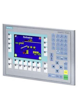
| Article Number (Market Facing Number) | 6AV66470AD113AX0 | 6AV66470AD113AX0 |
| Product Description | *** spare part *** SIMATIC HMI KTP600 Basic Color PN, Basic Panel, key/touch operation, 6" TFT display, 256 colors, PROFINET interface, configurable as of WinCC flexible 2008 SP2 Compact/ WinCC Basic V10.5/ STEP 7 Basic V10.5, contains open-source software, which is provided free of charge see enclosed CD |
| Product family | Not available |
| Product Lifecycle (PLM) | PM410:Product cancellation |
| Additional Product Information | |
| EAN | 6940408100565 |
| UPC | 040892549317 |
| Commodity Code | 85371091 |
| LKZ_FDB/ CatalogID | ST80E |
| Product Group | 4548 |
| Group Code | R141 |
| Country of origin | China |
| SCIP number | Not available |
| Delivery information | |
| Net Weight (lb) | 3.003 lb |
| Package size unit of measure | Inch |
| Packaging Quantity | 1 |
| Product | |
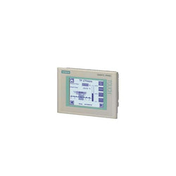
| Article Number (Market Facing Number) | 6AV66430BA011AX0 | 6AV66430BA011AX0 |
| Product Description | *** spare part *** SIMATIC OP 277 6" operator panel 5.7" TFT display 4 MB configuration memory, configurable with WinCC flexible 2005 Standard SP1 |
| Product family | Not available |
| Product Lifecycle (PLM) | PM410:Product cancellation |
| Additional Product Information | |
| EAN | 4025515074137 |
| UPC | 662643209549 |
| Commodity Code | 85371098 |
| LKZ_FDB/ CatalogID | ST80E |
| Product Group | 4357 |
| Group Code | R141 |
| Country of origin | Germany |
| SCIP number | Not available |
| Delivery information | |
| Net Weight (lb) | 4.187 lb |
| Package size unit of measure | Inch |
| Packaging Quantity | 1 |
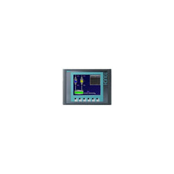
| Product | |
| Article Number (Market Facing Number) | 6AV66400CA110AX1 | 6AV66400CA110AX1 |
| Product Description | *** Spare part *** SIMATIC Touch Panel TP 177micro for SIMATIC S7-200 5.7" blue mode STN display configurable from WinCC flexible 2004 Micro HSP Contains open source software which is provided free of charge. See enclosed CD |
| Product family | Not available |
| Product Lifecycle (PLM) | PM500:Discontinued Product or end of PLM & Support |
| Additional Product Information | |
| EAN | 4025515076469 |
| UPC | Not available |
| Commodity Code | 85371098 |
| LKZ_FDB/ CatalogID | ST80E |
| Product Group | 4182 |
| Group Code | R141 |
| Country of origin | Germany |
| SCIP number | Not available |
| Delivery information | |
| Net Weight (lb) | 2.202 lb |
| Package size unit of measure | Inch |
| Packaging Quantity | 1 |

This product is part of the Modicon M241 range, an offer of logic controllers for performance demanding applications. This logic controller provides 24 discrete, 8 fast inputs, 16 transistor, 4 fast outputs with ethernet PNP transistor output. It is a Modicon logic controller with a rated supply/output voltage of 24V DC and an output current of 0.5A for transistor output, 0.1A for fast output current with sink or source input logic positive output logic. This product enables to build application intuitively as never before due to an organised screen design. Integrated connections are USB port with mini B USB 2.0, non isolated serial link 1 with RJ45 and RS232/RS485 interface, non isolated serial link 2 with removable screw terminal block and RS485 interface and ethernet with RJ45 . It is a Modicon M241 controller with 8MB for program, 64MB for system memory RAM, 128MB built-in flash memory for backup of user programs and a SD card memory capacity of 16GB. It is an IP20 rated product. Its dimensions are 190mm (Width) x 95mm (Depth) x 90mm (Height). It weighs 0.62kg. The Modicon M241 logic controllers are designed for high-performance compact machines incorporating speed and position control functions. This product is certified by CE, IACS E10, CSA, RCM and CULus. It meets ANSI/ISA 12-12-01, CSA C22.2 No 142, CSA C22.2 No 213, EN/IEC 61131-22007, marine specification (LR, ABS, DNV, GL), UL 1604 and UL 508 standards. It supports DIN rail mount. Achieve benchmark performance while increasing profitability with the Modicon M241 through intuitive machine programming with EcoStruxure Machine Expert, ready-to-use applications and function blocks.
Main
| Characteristic | Value(s) |
|---|---|
| Range of Product | Modicon M241 |
| Product or Component Type | Logic controller |
| [Us] rated supply voltage | 24 V DC |
| Discrete input number | 24, discrete input 8 fast input IEC 61131-2 Type 1 |
| Discrete output type | Transistor |
| Discrete output number | 16 transistor 4 fast output |
| Discrete output voltage | 24 V DC transistor output |
| Discrete output current | 0.1 A fast output (PTO mode) Q0...Q3) 0.5 A transistor output Q0...Q15) |
Complementary
| Characteristic | Value(s) |
|---|---|
| Discrete I/O number | 40 |
| Maximum number of I/O expansion module | 7 (local I/O-Architecture) 14 (remote I/O-Architecture) |
| Supply voltage limits | 20.4â¦28.8 V |
| Inrush current | 50 A |
| Power consumption in W | 32.6â¦40.4 W with max number of I/O expansion module) |
| Discrete input logic | Sink or source |
| Discrete input voltage | 24 V |
| Discrete input voltage type | DC |
| Voltage state 1 guaranteed | >= 15 V input |
| Voltage state 0 guaranteed | <= 5 V input |
| Discrete input current | 10.7 mA fast input 7 mA input |
| Input impedance | 4.7 kOhm input 2.81 kOhm fast input |
| Response time | <= 2 µs turn-on, I0...I7 fast input <= 2 µs turn-off, I0...I7 fast input <= 2 µs turn-on, Q0...Q3 fast output <= 2 µs turn-off, Q0...Q3 fast output 50 µs turn-on, I0...I15 input 50 µs turn-off, I0...I15 input <= 34 µs turn-on, Q0...Q15 output <= 250 µs turn-off, Q0...Q15 output |
| Configurable filtering time | 1 µs fast input 12 ms fast input 0 ms input 1 ms input 4 ms input 12 ms input |
| Discrete output logic | Positive logic (source) |
| Output voltage limits | 30 V DC |
| Maximum current per output common | 2 A |
| Maximum output frequency | 20 kHz fast output (PWM mode) 100 kHz fast output (PLS mode) 1 kHz output |
| Accuracy | +/- 0.1 % 0.02â¦0.1 kHz fast output +/- 1 % 0.1â¦1 kHz fast output |
| Maximum leakage current | 5 µA output |
| Maximum voltage drop | <1 V |
| Maximum tungsten load | <2.4 W |
| Protection type | Short-circuit protection Short-circuit and overload protection with automatic reset Reverse polarity protection fast output |
| Reset time | 10 ms automatic reset output 12 s automatic reset fast output |
| Memory capacity | 64 MB system memory RAM |
| Data backed up | 128 MB built-in flash memory backup of user programs |
| Data storage equipment | <= 16 GB SD card optional) |
| Battery type | BR2032 lithium non-rechargeable 4 year(s) |
| Backup time | 2 years 77 °F (25 °C) |
| Execution time for 1 KInstruction | 0.3 ms event and periodic task 0.7 ms other instruction |
| Application structure | 3 cyclic master tasks + 1 freewheeling task 8 external event tasks 4 cyclic master tasks 8 event tasks |
| Realtime clock | With |
| Clock drift | <= 60 s/month 77 °F (25 °C) |
| Positioning functions | PTO 4 100 kHz) PTO 4 transistor output 1 kHz) |
| Counting input number | 4 fast input (HSC mode) 200 kHz 16 standard input 1 kHz |
| Control signal type | A/B 100 kHz fast input (HSC mode) Pulse/direction 200 kHz fast input (HSC mode) Single phase 200 kHz fast input (HSC mode) |
| Integrated connection type | Non isolated serial link serial 1 RJ45 RS232/RS485 Non isolated serial link serial 2 removable screw terminal block RS485 USB port mini B USB 2.0 Ethernet RJ45 |
| Supply | Serial 1)serial link supply 5 V, <200 mA |
| Transmission rate | 1.2...115.2 kbit/s (115.2 kbit/s by default) 49.2 ft (15 m) RS485 1.2...115.2 kbit/s (115.2 kbit/s by default) 9.8 ft (3 m) RS232 480 Mbit/s 9.8 ft (3 m) USB 10/100 Mbit/s Ethernet |
| Communication port protocol | Non isolated serial link Modbus master/slave |
| Port Ethernet | 10BASE-T/100BASE-TX - 1 copper cable |
| ethernet services | FDR DHCP server via TM4 Ethernet switch network module DHCP client embedded Ethernet port SMS notifications Updating firmware SNMP client/server Programming NGVL Monitoring IEC VAR ACCESS FTP client/server Downloading SQL client Modbus TCP client I/O scanner Ethernet/IP originator I/O scanner embedded Ethernet port Ethernet/IP target, Modbus TCP server and Modbus TCP slave Send and receive email from the controller based on TCP/UDP library Web server (WebVisu & XWeb system) OPC UA server DNS client |
| Local signalling | 1 LED (green) for PWR 1 LED (green) for RUN 1 LED (red) for module error (ERR) 1 LED (red) for I/O error (I/O) 1 LED (green) for SD card access (SD) 1 LED (red) for BAT 1 LED (green) for SL1 1 LED (green) for SL2 1 LED (red) for bus fault on TM4 (TM4) 1 LED per channel (green) for I/O state 1 LED (green) for Ethernet port activity |
| Electrical connection | removable screw terminal block for inputs and outputs pitch 5.08 mm) removable screw terminal block for connecting the 24 V DC power supply pitch 5.08 mm) |
| Maximum cable distance between devices | Unshielded cable <164.04 ft (50 m) input Shielded cable <32.8 ft (10 m) fast input Unshielded cable <164.04 ft (50 m) output Shielded cable <9.8 ft (3 m) fast output |
| Insulation | Between supply and internal logic 500 V AC Non-insulated between supply and ground Between input and internal logic 500 V AC Non-insulated between inputs Between fast input and internal logic 500 V AC Between output and internal logic 500 V AC Non-insulated between outputs Between fast output and internal logic 500 V AC Between output groups 500 V AC |
| Marking | CE |
| Surge withstand | 1 kV power lines (DC) common mode IEC 61000-4-5 1 kV shielded cable common mode IEC 61000-4-5 0.5 kV power lines (DC) differential mode IEC 61000-4-5 1 kV relay output differential mode IEC 61000-4-5 1 kV input common mode IEC 61000-4-5 1 kV transistor output common mode IEC 61000-4-5 |
| Web services | Web server |
| Maximum number of connections | 8 Modbus server 8 SoMachine protocol 10 web server 4 FTP server 16 Ethernet/IP target 8 Modbus client |
| Number of server device(s) | 64 Modbus TCP 16 EtherNet/IP |
| Cycle time | 10 ms 16 EtherNet/IP 64 ms 64 Modbus TCP |
| Mounting support | Top hat type TH35-15 rail IEC 60715 Top hat type TH35-7.5 rail IEC 60715 plate or panel with fixing kit |
| Height | 3.5 in (90 mm) |
| Depth | 3.7 in (95 mm) |
| Width | 7.5 in (190 mm) |
| Product Weight | 1.37 lb(US) (0.62 kg) |

Variable Speed Drive - ATV930 - 3kW - 400/480V - with braking unit - IP21

Variable Speed Drive - ATV930 - 2,2kW - 400/480V - with braking unit - IP21
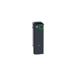
Variable Speed Drive - ATV930 - 55kW - 400/480V - with braking unit - IP21
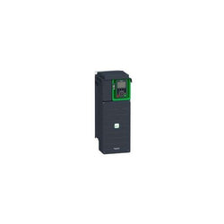
This Altivar Process ATV900 variable speed drive can feed 3-phase synchronous and asynchronous power motors. It is suitable for motors with power rating up to 18.5kW/25hp for applications requiring slight overload (up to 120%). It is suitable for motors with power rating up to 15kW/20hp for applications requiring significant overload (up to 150%). It works at a rated supply voltage from 380V to 480V AC. This variable speed / frequency drive (VSD / VFD) is specifically designed for industrial processes. In the following market segments, oil and gas, mining, minerals and metals, food and beverage water and wastewater. It offers high motor performance on any motor and total control of any kind of coupling in master/slave applications. Network services help ensure operation continuity even in case of connection breakdown. Web server and data logging help reduce downtime through fast troubleshooting and preventive maintenance. Its advanced connectivity, including EtherNet/IP and Modbus TCP, allows deep integration into automation architectures. It is designed to be mounted in vertical position (+/- 10 °) on a wall.
Main
| Characteristic | Value(s) |
|---|---|
| Range of Product | Altivar Process ATV900 |
| Product Specific Application | Process for industrial |
| Product or Component Type | Variable speed drive |
| Variant | With braking chopper Standard version |
| Device Application | Industrial Application |
| Product destination | Asynchronous motors Synchronous motors |
| Phase | 3 phase |
| Mounting Mode | Wall mount |
| Continuous output current | 39.2 A 4 kHz normal duty 31.7 A 4 kHz heavy duty |
| Communication Port Protocol | Modbus TCP EtherNet/IP Modbus serial |
| Option card | Slot A communication module Profibus DP V1 Slot A communication module PROFINET Slot A communication module DeviceNet Slot A communication module EtherCAT Slot A communication module CANopen daisy chain RJ45 Slot A communication module CANopen SUB-D 9 Slot A communication module CANopen screw terminals Slot A/slot B/slot C digital and analog I/O extension module Slot A/slot B/slot C output relay extension module Slot B 5/12 V digital encoder interface module Slot B analog encoder interface module Slot B resolver encoder interface module communication module Ethernet Powerlink |
| [Us] rated supply voltage | 380...480 V - 15...10 % |
| [Us] rated supply voltage | 380...480 V |
| Relative symmetric mains voltage tolerance | 10 % |
| Relative symmetric network frequency tolerance | 5 % |
| nominal output current | 39.2 A |
| Motor power kW | 18.5 kW normal duty 15.0 kW heavy duty |
| EMC filter | Integrated With EMC plate option |
| IP degree of protection | IP21 |
| Degree of protection | UL type 1 |
Complementary
| Characteristic | Value(s) |
|---|---|
| Electrical connection | Control screw terminal 0.5...1.5 mm² AWG 20...AWG 16 Line side screw terminal 10...16 mm² AWG 8...AWG 6 Motor screw terminal 10...16 mm² AWG 8...AWG 6 DC bus screw terminal 10...16 mm² AWG 8...AWG 6 |
| Transmission Rate | 10/100 Mbit/s Ethernet IP/Modbus TCP 4.8, 9.6, 19.2, 38.4 kbit/s Modbus serial |
| Exchange mode | Half duplex, full duplex, autonegotiation Ethernet IP/Modbus TCP |
| Data format | 8 bits, configurable odd, even or no parity Modbus serial |
| Type of polarization | No impedance Modbus serial |
| Number of addresses | 1â¦247 Modbus serial |
| Supply | External supply for digital inputs 24 V DC 19â¦30 V), <1.25 mA overload and short-circuit protection Internal supply for reference potentiometer (1 to 10 kOhm) 10.5 V DC +/- 5 %, <10 mA overload and short-circuit protection Internal supply for digital inputs and STO 24 V DC 21â¦27 V), <200 mA overload and short-circuit protection |
| Local signalling | Local diagnostic: 3 LED (mono/dual colour) Embedded communication status: 5 LED (dual colour) Communication module status: 2 LED (dual colour) Presence of voltage: 1 LED (red) |
| Input compatibility | DI1...DI8 discrete input level 1 PLC IEC 61131-2 DI7, DI8 pulse input level 1 PLC IEC 65A-68 STOA, STOB discrete input level 1 PLC IEC 61131-2 |
| Discrete input logic | Positive logic (source) DI1...DI8), < 5 V, > 11 V Negative logic (sink) DI1...DI8), > 16 V, < 10 V Positive logic (source) DI7, DI8), < 0.6 V, > 2.5 V Positive logic (source) STOA, STOB), < 5 V, > 11 V |
| Sampling duration | 2 ms +/- 0.5 ms DI1...DI8) - discrete input 5 ms +/- 1 ms DI7, DI8) - pulse input 1 ms +/- 1 ms AI1, AI2, AI3) - analog input 5 ms +/- 1 ms AQ1, AQ2) - analog output |
| Accuracy | +/- 0.6 % AI1, AI2, AI3 for a temperature variation 60 °C analog input +/- 1 % AQ1, AQ2 for a temperature variation 60 °C analog output |
| Linearity error | AI1, AI2, AI3 +/- 0.15 % of maximum value analog input AQ1, AQ2 +/- 0.2 % analog output |
| Refresh time | Relay output R1, R2, R3)5 ms +/- 0.5 ms) |
| Isolation | Between power and control terminals |
| Discrete input number | 10 |
| Discrete input type | DI1...DI8 programmable, 24 V DC <= 30 V)3.5 kOhm DI7, DI8 programmable as pulse input 0â¦30 kHz, 24 V DC <= 30 V) STOA, STOB safe torque off, 24 V DC <= 30 V)> 2.2 kOhm |
| Discrete input logic | 16 preset speeds |
| Discrete output number | 2 |
| Discrete output type | Logic output DQ+ 0â¦1 kHz <= 30 V DC 100 mA Programmable as pulse output DQ+ 0â¦30 kHz <= 30 V DC 20 mA Logic output DQ- 0â¦1 kHz <= 30 V DC 100 mA |
| Analogue input number | 3 |
| Analogue input type | AI1, AI2, AI3 software-configurable voltage 0...10 V DC 30 kOhm 12 bits AI1, AI2, AI3 software-configurable current 0...20 mA/4...20 mA 250 Ohm 12 bits |
| Analogue output number | 2 |
| Analogue output type | Software-configurable voltage AQ1, AQ2 0...10 V DC 470 Ohm 10 bits Software-configurable current AQ1, AQ2 0...20 mA 500 Ohm 10 bits |
| Relay output number | 3 |
| Relay output type | Configurable relay logic R1 fault relay NO/NC 100000 cycles Configurable relay logic R2 sequence relay NO 1000000 cycles Configurable relay logic R3 sequence relay NO 1000000 cycles |
| Maximum switching current | Relay output R1 resistive, cos phi = 1 3 A 250 V AC Relay output R1 resistive, cos phi = 1 3 A 30 V DC Relay output R1 inductive, cos phi = 0.4 7 ms 2 A 250 V AC Relay output R1 inductive, cos phi = 0.4 7 ms 2 A 30 V DC Relay output R2, R3 resistive, cos phi = 1 5 A 250 V AC Relay output R2, R3 resistive, cos phi = 1 5 A 30 V DC Relay output R2, R3 inductive, cos phi = 0.4 7 ms 2 A 250 V AC Relay output R2, R3 inductive, cos phi = 0.4 7 ms 2 A 30 V DC |
| Minimum switching current | Relay output R1, R2, R3 5 mA 24 V DC |
| Physical interface | Ethernet 2-wire RS 485 |
| Connector Type | 2 RJ45 1 RJ45 |
| Method of access | Slave Modbus TCP |
| Transmission Rate | 10, 100 Mbits 4.8 kbps 9600 bit/s 19200 bit/s |
| Transmission frame | RTU |
| Number of addresses | 1â¦247 |
| Data format | 8 bits, configurable odd, even or no parity |
| Type of polarization | No impedance |
| 4 quadrant operation possible | True |
| Asynchronous motor control profile | Constant torque standard Variable torque standard Optimized torque mode |
| Synchronous motor control profile | Permanent magnet motor Synchronous reluctance motor |
| Maximum output frequency | 599 Hz |
| Acceleration and deceleration ramps | Linear adjustable separately from 0.01...9999 s |
| Motor slip compensation | Adjustable Automatic whatever the load Not available in permanent magnet motor law Can be suppressed |
| Switching frequency | 2...16 kHz adjustable 4...16 kHz with derating factor |
| Nominal switching frequency | 4 kHz |
| Braking to standstill | By DC injection |
| Brake chopper integrated | True |
| Line current | 33.4 A 380 V normal duty) 27.7 A 380 V heavy duty) 28.9 A 480 V normal duty) 24.4 A 480 V heavy duty) |
| Maximum Input Current per Phase | 33.4 A |
| Maximum output voltage | 480.0 V |
| Apparent power | 24 kVA 480 V normal duty) 20.3 kVA 480 V heavy duty) |
| Maximum transient current | 47 A 60 s normal duty) 47.6 A 60 s heavy duty) |
| Network Frequency | 50-60 Hz |
| Prospective line Isc | 50 kA |
| Base load current at high overload | 31.7 A |
| Base load current at low overload | 39.2 A |
| Power dissipation in W | Natural convection 67 W 380 V 4 kHz Forced convection 460 W 380 V 4 kHz |
| With safety function Safely Limited Speed (SLS) | True |
| With safety function Safe brake management (SBC/SBT) | True |
| With safety function Safe Operating Stop (SOS) | False |
| With safety function Safe Position (SP) | False |
| With safety function Safe programmable logic | False |
| With safety function Safe Speed Monitor (SSM) | False |
| With safety function Safe Stop 1 (SS1) | True |
| With sft fct Safe Stop 2 (SS2) | False |
| With safety function Safe torque off (STO) | True |
| With safety function Safely Limited Position (SLP) | False |
| With safety function Safe Direction (SDI) | False |
| Protection type | Thermal protection motor Safe torque off motor Motor phase break motor Thermal protection drive Safe torque off drive Overheating drive Overcurrent between output phases and earth drive Overload of output voltage drive Short-circuit protection drive Motor phase break drive Overvoltages on the DC bus drive Line supply overvoltage drive Line supply undervoltage drive Line supply phase loss drive Overspeed drive Break on the control circuit drive |
| Quantity per Set | 1 |
| Width | 8.3 in (211 mm) |
| Height | 21.5 in (545.9 mm) |
| Depth | 9.3 in (235 mm) |
| Product Weight | 31.3 lb(US) (14.2 kg) |

Main
| Characteristic | Value(s) |
|---|---|
| Range of Product | Altivar 71 |
| Product or Component Type | Variable speed drive |
| Product Specific Application | Complex, high-power machines |
| Component name | ATV71 |
| Motor power kW | 1.5 kW, 3 phase 380...480 V |
| Maximum Horse Power Rating | 2 hp, 3 phase 380...480 V |
| Maximum motor cable length | 164.04 ft (50 m) shielded cable 328.08 ft (100 m) unshielded cable |
| power supply voltage | 380...480 V - 15...10 % |
| Phase | 3 phase |
| Line current | 5.3 A 480 V 3 phase 1.5 kW / 2 hp 5.8 A 380 V 3 phase 1.5 kW / 2 hp |
| EMC filter | Integrated |
| Assembly style | With heat sink |
| Apparent power | 3.8 kVA 380 V 3 phase 1.5 kW / 2 hp |
| Prospective line Isc | 5 kA 3 phase |
| Nominal output current | 3.4 A 4 kHz 460 V 3 phase 1.5 kW / 2 hp 4.1 A 4 kHz 380 V 3 phase 1.5 kW / 2 hp |
| Maximum transient current | 6.2 A 60 s 3 phase 1.5 kW / 2 hp 6.8 A 2 s 3 phase 1.5 kW / 2 hp |
| Output frequency | 0.1â¦599 Hz |
| Nominal switching frequency | 4 kHz |
| Switching frequency | 1...16 kHz adjustable 4...16 kHz with derating factor |
| Asynchronous motor control profile | Flux vector control (FVC) with sensor (current vector) Sensorless flux vector control (SFVC) (voltage or current vector) ENA (Energy adaptation) system for unbalanced loads Voltage/frequency ratio (2 or 5 points) |
| Type of polarization | No impedance Modbus |
Complementary
| Characteristic | Value(s) |
|---|---|
| Product destination | Synchronous motors Asynchronous motors |
| power supply voltage limits | 323â¦528 V |
| power supply frequency | 50...60 Hz - 5...5 % |
| power supply frequency limits | 47.5...63 Hz |
| Speed range | 1â¦100 asynchronous motor in open-loop mode, without speed feedback 1â¦1000 asynchronous motor in closed-loop mode with encoder feedback 1â¦50 synchronous motor in open-loop mode, without speed feedback |
| Speed accuracy | +/- 0.01 % of nominal speed in closed-loop mode with encoder feedback 0.2 Tn to Tn +/- 10 % of nominal slip without speed feedback 0.2 Tn to Tn |
| Torque accuracy | +/- 15 % in open-loop mode, without speed feedback +/- 5 % in closed-loop mode with encoder feedback |
| Transient overtorque | 170 % +/- 10 % 60 s every 10 minutes 220 % +/- 10 % 2 s |
| Braking torque | <= 150 % with braking or hoist resistor 30 % without braking resistor |
| Synchronous motor control profile | Vector control without speed feedback |
| Regulation loop | Adjustable PI regulator |
| Motor slip compensation | Suppressable Adjustable Not available in voltage/frequency ratio (2 or 5 points) Automatic whatever the load |
| diagnostic | 1 LED (red) for drive voltage |
| Output voltage | <= power supply voltage |
| Insulation | Electrical between power and control |
| type of cable for mounting in an enclosure | With a NEMA Type1 kit 3 UL 508 cable 104 °F (40 °C), copper 75 °C / PVC With an IP21 or an IP31 kit 3 IEC cable 104 °F (40 °C), copper 70 °C / PVC Without mounting kit 1 IEC cable 113 °F (45 °C), copper 70 °C / PVC Without mounting kit 1 IEC cable 113 °F (45 °C), copper 90 °C / XLPE/EPR |
| Electrical connection | Terminal 2.5 mm², AWG 14 AI1-/AI1+, AI2, AO1, R1A, R1B, R1C, R2A, R2B, LI1...LI6, PWR) Terminal 4 mm², AWG 10 L1/R, L2/S, L3/T, U/T1, V/T2, W/T3, PC/-, PO, PA/+, PA, PB) |
| Tightening torque | 5.3 lbf.in (0.6 N.m) AI1-/AI1+, AI2, AO1, R1A, R1B, R1C, R2A, R2B, LI1...LI6, PWR) 12.4 lbf.in (1.4 N.m), 12.3 lb.in L1/R, L2/S, L3/T, U/T1, V/T2, W/T3, PC/-, PO, PA/+, PA, PB) |
| Supply | Internal supply for reference potentiometer (1 to 10 kOhm) 10.5 V DC +/- 5 %, <10 mA overload and short-circuit protection Internal supply 24 V DC 21â¦27 V), <200 mA overload and short-circuit protection |
| Analogue input number | 2 |
| Analogue input type | AI1-/Al1+ bipolar differential voltage +/- 10 V DC 24 V max 11 bits + sign AI2 software-configurable current 0...20 mA 242 Ohm 11 bits AI2 software-configurable voltage 0...10 V DC 24 V max 30000 Ohm 11 bits |
| input sampling time | 2 ms +/- 0.5 ms AI1-/Al1+) - analog 2 ms +/- 0.5 ms Al2) - analog 2 ms +/- 0.5 ms LI1...LI5) - discrete 2 ms +/- 0.5 ms LI6)if configured as logic input - discrete |
| Response time | <= 100 ms in STO (Safe Torque Off) AO1 2 ms +/- 0.5 ms analog R1A, R1B, R1C 7 ms +/- 0.5 ms discrete R2A, R2B 7 ms +/- 0.5 ms discrete |
| absolute accuracy precision | +/- 0.6 % AI1-/Al1+) for a temperature variation 60 °C +/- 0.6 % AI2) for a temperature variation 60 °C +/- 1 % AO1) for a temperature variation 60 °C |
| Linearity error | +/- 0.15 % of maximum value AI1-/Al1+, AI2) +/- 0.2 % AO1) |
| Analogue output number | 1 |
| Analogue output type | AO1 software-configurable logic output 10 V 20 mA AO1 software-configurable current 0...20 mA 500 Ohm 10 bits AO1 software-configurable voltage 0...10 V DC 470 Ohm 10 bits |
| Discrete output number | 2 |
| Discrete output type | Configurable relay logic R1A, R1B, R1C) NO/NC - 100000 cycles Configurable relay logic R2A, R2B) NO - 100000 cycles |
| Minimum switching current | 3 mA 24 V DC configurable relay logic |
| Maximum switching current | R1, R2 2 A 250 V AC inductive, cos phi = 0.4 R1, R2 2 A 30 V DC inductive, cos phi = 0.4 R1, R2 5 A 250 V AC resistive, cos phi = 1 R1, R2 5 A 30 V DC resistive, cos phi = 1 |
| Discrete input number | 7 |
| Discrete input type | LI1...LI5 programmable 24 V DC level 1 PLC 3500 Ohm LI6 switch-configurable 24 V DC level 1 PLC 3500 Ohm LI6 switch-configurable PTC probe 0â¦6 1500 Ohm PWR safety input 24 V DC 1500 Ohm ISO 13849-1 level d |
| Discrete input logic | Negative logic (sink) LI1...LI5), > 16 V, < 10 V Positive logic (source) LI1...LI5), < 5 V, > 11 V Negative logic (sink) LI6)if configured as logic input, > 16 V, < 10 V Positive logic (source) LI6)if configured as logic input, < 5 V, > 11 V |
| Acceleration and deceleration ramps | S, U or customized Linear adjustable separately from 0.01 to 9000 s Automatic adaptation of ramp if braking capacity exceeded, by using resistor |
| Braking to standstill | By DC injection |
| Protection type | Against exceeding limit speed drive Against input phase loss drive Break on the control circuit drive Input phase breaks drive Line supply overvoltage drive Line supply undervoltage drive Overcurrent between output phases and earth drive Overheating protection drive Overvoltages on the DC bus drive Short-circuit between motor phases drive Thermal protection drive Motor phase break motor Power removal motor Thermal protection motor |
| Insulation resistance | > 1 mOhm 500 V DC for 1 minute to earth |
| Frequency resolution | Analog input 0.024/50 Hz Display unit 0.1 Hz |
| Communication Port Protocol | CANopen Modbus |
| Connector type | 1 RJ45 on front face)Modbus 1 RJ45 on terminal)Modbus Male SUB-D 9 on RJ45CANopen |
| Physical interface | 2-wire RS 485 Modbus |
| Transmission frame | RTU Modbus |
| Transmission rate | 4800 bps, 9600 bps, 19200 bps, 38.4 Kbps Modbus on terminal 9600 bps, 19200 bps Modbus on front face 20 kbps, 50 kbps, 125 kbps, 250 kbps, 500 kbps, 1 Mbps CANopen |
| Data format | 8 bits, 1 stop, even parity Modbus on front face 8 bits, odd even or no configurable parity Modbus on terminal |
| Number of addresses | 1â¦127 CANopen 1â¦247 Modbus |
| Method of access | Slave CANopen |
| Marking | CE |
| Operating position | Vertical +/- 10 degree |
| Height | 9.06 in (230 mm) |
| Depth | 6.9 in (175 mm) |
| Width | 5.1 in (130 mm) |
| Product Weight | 6.6 lb(US) (3 kg) |
| Functionality | Full |
| Specific application | Other applications |
| Option card | Communication card CC-Link Controller inside programmable card Communication card DeviceNet Communication card EtherNet/IP Communication card Fipio I/O extension card Communication card Interbus-S Interface card for encoder Communication card Modbus Plus Communication card Modbus TCP Communication card Modbus/Uni-Telway Overhead crane card Communication card Profibus DP Communication card Profibus DP V1 |

Variable Speed Drive Altivar 71 - 55kW-75hp - 480V - with EMC filter whitout Graphic Terminal

Main
| Characteristic | Value(s) |
|---|---|
| Range of Product | Altivar 71 |
| Product or Component Type | Variable speed drive |
| Product Specific Application | Complex, high-power machines |
| Component name | ATV71 |
| Motor power kW | 0.75 kW, 3 phase 380...480 V |
| Maximum Horse Power Rating | 1 hp, 3 phase 380...480 V |
| Maximum motor cable length | 164.04 ft (50 m) shielded cable 328.08 ft (100 m) unshielded cable |
| power supply voltage | 380...480 V - 15...10 % |
| Phase | 3 phase |
| Line current | 3 A 480 V 3 phase 0.75 kW / 1 hp 3.7 A 380 V 3 phase 0.75 kW / 1 hp |
| EMC filter | Integrated |
| Assembly style | With heat sink |
| Variant | Without remote graphic terminal |
| Apparent power | 2.4 kVA 380 V 3 phase 0.75 kW / 1 hp |
| Prospective line Isc | 5 kA 3 phase |
| Nominal output current | 2.1 A 4 kHz 460 V 3 phase 0.75 kW / 1 hp 2.3 A 4 kHz 380 V 3 phase 0.75 kW / 1 hp |
| Maximum transient current | 3.5 A 60 s 3 phase 0.75 kW / 1 hp 3.8 A 2 s 3 phase 0.75 kW / 1 hp |
| Output frequency | 0.1â¦599 Hz |
| Nominal switching frequency | 4 kHz |
| Switching frequency | 1...16 kHz adjustable 4...16 kHz with derating factor |
| Asynchronous motor control profile | ENA (Energy adaptation) system for unbalanced loads Flux vector control (FVC) with sensor (current vector) Sensorless flux vector control (SFVC) (voltage or current vector) Voltage/frequency ratio (2 or 5 points) |
| Type of polarization | No impedance Modbus |
Complementary
| Characteristic | Value(s) |
|---|---|
| Product destination | Asynchronous motors Synchronous motors |
| power supply voltage limits | 323â¦528 V |
| power supply frequency | 50...60 Hz - 5...5 % |
| power supply frequency limits | 47.5...63 Hz |
| Speed range | 1â¦100 asynchronous motor in open-loop mode, without speed feedback 1â¦1000 asynchronous motor in closed-loop mode with encoder feedback 1â¦50 synchronous motor in open-loop mode, without speed feedback |
| Speed accuracy | +/- 0.01 % of nominal speed in closed-loop mode with encoder feedback 0.2 Tn to Tn +/- 10 % of nominal slip without speed feedback 0.2 Tn to Tn |
| Torque accuracy | +/- 15 % in open-loop mode, without speed feedback +/- 5 % in closed-loop mode with encoder feedback |
| Transient overtorque | 170 % +/- 10 % 60 s every 10 minutes 220 % +/- 10 % 2 s |
| Braking torque | <= 150 % with braking or hoist resistor 30 % without braking resistor |
| Synchronous motor control profile | Vector control without speed feedback |
| Regulation loop | Adjustable PI regulator |
| Motor slip compensation | Suppressable Automatic whatever the load Adjustable Not available in voltage/frequency ratio (2 or 5 points) |
| diagnostic | 1 LED (red) for drive voltage |
| Output voltage | <= power supply voltage |
| Insulation | Electrical between power and control |
| type of cable for mounting in an enclosure | With a NEMA Type1 kit 3 UL 508 cable 104 °F (40 °C), copper 75 °C / PVC With an IP21 or an IP31 kit 3 IEC cable 104 °F (40 °C), copper 70 °C / PVC Without mounting kit 1 IEC cable 113 °F (45 °C), copper 70 °C / PVC Without mounting kit 1 IEC cable 113 °F (45 °C), copper 90 °C / XLPE/EPR |
| Electrical connection | Terminal 2.5 mm², AWG 14 AI1-/AI1+, AI2, AO1, R1A, R1B, R1C, R2A, R2B, LI1...LI6, PWR) Terminal 4 mm², AWG 10 L1/R, L2/S, L3/T, U/T1, V/T2, W/T3, PC/-, PO, PA/+, PA, PB) |
| Tightening torque | 5.3 lbf.in (0.6 N.m) AI1-/AI1+, AI2, AO1, R1A, R1B, R1C, R2A, R2B, LI1...LI6, PWR) 12.4 lbf.in (1.4 N.m), 12.3 lb.in L1/R, L2/S, L3/T, U/T1, V/T2, W/T3, PC/-, PO, PA/+, PA, PB) |
| Supply | Internal supply for reference potentiometer (1 to 10 kOhm) 10.5 V DC +/- 5 %, <10 mA overload and short-circuit protection Internal supply 24 V DC 21â¦27 V), <200 mA overload and short-circuit protection |
| Analogue input number | 2 |
| Analogue input type | AI1-/Al1+ bipolar differential voltage +/- 10 V DC 24 V max 11 bits + sign AI2 software-configurable current 0...20 mA 242 Ohm 11 bits AI2 software-configurable voltage 0...10 V DC 24 V max 30000 Ohm 11 bits |
| input sampling time | 2 ms +/- 0.5 ms AI1-/Al1+) - analog 2 ms +/- 0.5 ms Al2) - analog 2 ms +/- 0.5 ms LI1...LI5) - discrete 2 ms +/- 0.5 ms LI6)if configured as logic input - discrete |
| Response time | <= 100 ms in STO (Safe Torque Off) AO1 2 ms +/- 0.5 ms analog R1A, R1B, R1C 7 ms +/- 0.5 ms discrete R2A, R2B 7 ms +/- 0.5 ms discrete |
| absolute accuracy precision | +/- 0.6 % AI1-/Al1+) for a temperature variation 60 °C +/- 0.6 % AI2) for a temperature variation 60 °C +/- 1 % AO1) for a temperature variation 60 °C |
| Linearity error | +/- 0.15 % of maximum value AI1-/Al1+, AI2) +/- 0.2 % AO1) |
| Analogue output number | 1 |
| Analogue output type | AO1 software-configurable logic output 10 V 20 mA AO1 software-configurable current 0...20 mA 500 Ohm 10 bits AO1 software-configurable voltage 0...10 V DC 470 Ohm 10 bits |
| Discrete output number | 2 |
| Discrete output type | Configurable relay logic R1A, R1B, R1C) NO/NC - 100000 cycles Configurable relay logic R2A, R2B) NO - 100000 cycles |
| Minimum switching current | 3 mA 24 V DC configurable relay logic |
| Maximum switching current | R1, R2 2 A 250 V AC inductive, cos phi = 0.4 R1, R2 2 A 30 V DC inductive, cos phi = 0.4 R1, R2 5 A 250 V AC resistive, cos phi = 1 R1, R2 5 A 30 V DC resistive, cos phi = 1 |
| Discrete input number | 7 |
| Discrete input type | LI1...LI5 programmable 24 V DC level 1 PLC 3500 Ohm LI6 switch-configurable 24 V DC level 1 PLC 3500 Ohm LI6 switch-configurable PTC probe 0â¦6 1500 Ohm PWR safety input 24 V DC 1500 Ohm ISO 13849-1 level d |
| Discrete input logic | Negative logic (sink) LI1...LI5), > 16 V, < 10 V Positive logic (source) LI1...LI5), < 5 V, > 11 V Negative logic (sink) LI6)if configured as logic input, > 16 V, < 10 V Positive logic (source) LI6)if configured as logic input, < 5 V, > 11 V |
| Acceleration and deceleration ramps | Linear adjustable separately from 0.01 to 9000 s S, U or customized Automatic adaptation of ramp if braking capacity exceeded, by using resistor |
| Braking to standstill | By DC injection |
| Protection type | Against exceeding limit speed drive Against input phase loss drive Break on the control circuit drive Input phase breaks drive Line supply overvoltage drive Line supply undervoltage drive Overcurrent between output phases and earth drive Overheating protection drive Overvoltages on the DC bus drive Short-circuit between motor phases drive Thermal protection drive Motor phase break motor Power removal motor Thermal protection motor |
| Insulation resistance | > 1 mOhm 500 V DC for 1 minute to earth |
| Frequency resolution | Analog input 0.024/50 Hz Display unit 0.1 Hz |
| Communication Port Protocol | CANopen Modbus |
| Connector type | 1 RJ45 on front face)Modbus 1 RJ45 on terminal)Modbus Male SUB-D 9 on RJ45CANopen |
| Physical interface | 2-wire RS 485 Modbus |
| Transmission frame | RTU Modbus |
| Transmission rate | 4800 bps, 9600 bps, 19200 bps, 38.4 Kbps Modbus on terminal 9600 bps, 19200 bps Modbus on front face 20 kbps, 50 kbps, 125 kbps, 250 kbps, 500 kbps, 1 Mbps CANopen |
| Data format | 8 bits, 1 stop, even parity Modbus on front face 8 bits, odd even or no configurable parity Modbus on terminal |
| Number of addresses | 1â¦127 CANopen 1â¦247 Modbus |
| Method of access | Slave CANopen |
| Marking | CE |
| Operating position | Vertical +/- 10 degree |
| Height | 9.06 in (230 mm) |
| Depth | 6.9 in (175 mm) |
| Width | 5.1 in (130 mm) |
| Product Weight | 6.6 lb(US) (3 kg) |
| Option card | Communication card CC-Link Controller inside programmable card Communication card DeviceNet Communication card EtherNet/IP Communication card Fipio I/O extension card Communication card Interbus-S Interface card for encoder Communication card Modbus Plus Communication card Modbus TCP Communication card Modbus/Uni-Telway Overhead crane card Communication card Profibus DP Communication card Profibus DP V1 |
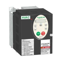
This Altivar 212 variable speed drive can feed 3-phase asynchronous motors. Its protection index is IP21 and it has a built-in EMC filter. It works at a rated power up to 1.5kW / 2hp and a rated voltage from 380V to 480V AC. Its design is based on eco-energy with a reduction in energy consumption of up to 70% compared to a conventional control system. Thanks to its cable temperature rise reduction technology, the Altivar 212 drive offers immediate, disturbance-free operation avoiding additional options such as a line choke or DC choke to deal with current harmonics. It weighs 2kg and its dimensions are, 107mm wide, 143mm high, 150mm deep. It is specifically designed for the most common fluid management applications in tertiary sector buildings (HVAC) like heating, ventilation, air conditioning and pumping. It conforms to international standards IEC/EN 61800-5-1 and IEC/EN 61800-3 (immunity and conducted and radiated EMC emissions). It is also CE, UL, CSA, C-Tick and NOM certified. The Altivar 212 offers optional motor chokes which can increase the maximum cable lengths between the drive and the motor and limit disturbance at the motor terminals. It is designed to be mounted in vertical position (+/- 10 °) on a panel, thanks to 4 fixing holes. It can also be mounted directly on a 35 mm wide DIN rail, thanks to the kit VW3A31852, to order separately. The Altivar 212 drive can easily be adapted to all building management systems thanks to its numerous functions and communication protocols integrated as standard, Modbus, METASYS N2, APOGEE FLN P1 and BACnet.
Main
| Characteristic | Value(s) |
|---|---|
| Device short name | ATV212 |
| Product destination | Asynchronous motors |
| Phase | 3 phase |
| Motor power kW | 1.5 kW |
| Maximum Horse Power Rating | 2 hp |
| Supply voltage limits | 323â¦528 V |
| Supply frequency | 50...60 Hz - 5...5 % |
| Line current | 2.5 A 480 V 3.2 A 380 V |
| Range of Product | Altivar 212 |
| Product or Component Type | Variable speed drive |
| Product Specific Application | Pumps and fans in HVAC |
| Communication Port Protocol | APOGEE FLN BACnet Modbus LonWorks METASYS N2 |
| [Us] rated supply voltage | 380...480 V - 15...10 % |
| EMC filter | Class C2 EMC filter integrated |
| IP degree of protection | IP21 |
Complementary
| Characteristic | Value(s) |
|---|---|
| Apparent power | 2.8 kVA 380 V |
| Continuous output current | 3.7 A 380 V 3.7 A 460 V |
| Maximum transient current | 4 A 60 s |
| Speed drive output frequency | 0.5â¦200 Hz |
| Speed range | 1â¦10 |
| Speed accuracy | +/- 10 % of nominal slip 0.2 Tn to Tn |
| Local signalling | 1 LED (red) for DC bus energized |
| Output voltage | <= power supply voltage |
| Isolation | Electrical between power and control |
| Type of cable | Without mounting kit 1 IEC cable 113 °F (45 °C), copper 90 °C / XLPE/EPR Without mounting kit 1 IEC cable 113 °F (45 °C), copper 70 °C / PVC With UL Type 1 kit 3 UL 508 cable 104 °F (40 °C), copper 75 °C / PVC |
| Electrical connection | VIA, VIB, FM, FLA, FLB, FLC, RY, RC, F, R, RES terminal 0.004 in² (2.5 mm²) / AWG 14 L1/R, L2/S, L3/T terminal 0.009 in² (6 mm²) / AWG 10 |
| Tightening torque | 11.5 lbf.in (1.3 N.m), 11.5 lb.in L1/R, L2/S, L3/T) 5.3 lbf.in (0.6 N.m) VIA, VIB, FM, FLA, FLB, FLC, RY, RC, F, R, RES) |
| Supply | Internal supply for reference potentiometer (1 to 10 kOhm) 10.5 V DC +/- 5 %, <10 A overload and short-circuit protection Internal supply 24 V DC 21â¦27 V), <200 A overload and short-circuit protection |
| Sampling duration | 2 ms +/- 0.5 ms F discrete 2 ms +/- 0.5 ms R discrete 2 ms +/- 0.5 ms RES discrete 3.5 ms +/- 0.5 ms VIA analog 22 ms +/- 0.5 ms VIB analog |
| Response time | FM 2 ms +/- 0.5 ms analog FLA, FLC 7 ms +/- 0.5 ms discrete FLB, FLC 7 ms +/- 0.5 ms discrete RY, RC 7 ms +/- 0.5 ms discrete |
| Accuracy | +/- 0.6 % VIA) for a temperature variation 60 °C +/- 0.6 % VIB) for a temperature variation 60 °C +/- 1 % FM) for a temperature variation 60 °C |
| Linearity error | VIA +/- 0.15 % of maximum value input VIB +/- 0.15 % of maximum value input FM +/- 0.2 % output |
| Analogue output type | FM switch-configurable voltage 0...10 V DC 7620 Ohm 10 bits FM switch-configurable current 0...20 mA 970 Ohm 10 bits |
| Discrete output type | Configurable relay logic FLA, FLC) NO - 100000 cycles Configurable relay logic FLB, FLC) NC - 100000 cycles Configurable relay logic RY, RC) NO - 100000 cycles |
| Minimum switching current | 3 mA 24 V DC configurable relay logic |
| Maximum switching current | 5 A 250 V AC resistive cos phi = 1 L/R = 0 ms FL, R) 5 A 30 V DC resistive cos phi = 1 L/R = 0 ms FL, R) 2 A 250 V AC inductive cos phi = 0.4 L/R = 7 ms FL, R) 2 A 30 V DC inductive cos phi = 0.4 L/R = 7 ms FL, R) |
| Discrete input type | F programmable 24 V DC level 1 PLC 4700 Ohm R programmable 24 V DC level 1 PLC 4700 Ohm RES programmable 24 V DC level 1 PLC 4700 Ohm |
| Discrete input logic | Positive logic (source) F, R, RES), <= 5 V, >= 11 V Negative logic (sink) F, R, RES), >= 16 V, <= 10 V |
| Dielectric strength | 3535 V DC between earth and power terminals 5092 V DC between control and power terminals |
| Insulation resistance | >= 1 mOhm 500 V DC for 1 minute |
| Frequency resolution | Display unit 0.1 Hz Analog input 0.024/50 Hz |
| Communication Service | Read device identification (43) Time out setting from 0.1 to 100 s Monitoring inhibitable Write single register (06) Read holding registers (03) 2 words maximum Write multiple registers (16) 2 words maximum |
| Option card | Communication card LonWorks |
| Power dissipation in W | 78 W |
| air flow | 7132.8 Gal/hr(US) (27 m3/h) |
| Functionality | Mid |
| Specific application | HVAC |
| Variable speed drive application selection | Building - HVAC compressor for scroll Building - HVAC fan Building - HVAC pump |
| Motor power range AC-3 | 1.1â¦2 kW 380â¦440 V 3 phase 1.1â¦2 kW 480â¦500 V 3 phase |
| Motor starter type | Variable speed drive |
| Discrete output number | 2 |
| Analogue input number | 2 |
| Analogue input type | VIA switch-configurable voltage 0...10 V DC 24 V max 30000 Ohm 10 bits VIB configurable voltage 0...10 V DC 24 V max 30000 Ohm 10 bits VIB configurable PTC probe 0...6 probes 1500 Ohm VIA switch-configurable current 0...20 mA 250 Ohm 10 bits |
| Analogue output number | 1 |
| Physical interface | 2-wire RS 485 |
| Connector Type | 1 open style 1 RJ45 |
| Transmission Rate | 9600 bps or 19200 bps |
| Transmission frame | RTU |
| Number of addresses | 1â¦247 |
| Data format | 8 bits, 1 stop, odd even or no configurable parity |
| Type of polarization | No impedance |
| Asynchronous motor control profile | Voltage/frequency ratio - Energy Saving, quadratic U/f Voltage/frequency ratio, 5 points Voltage/frequency ratio, automatic IR compensation (U/f + automatic Uo) Voltage/frequency ratio, 2 points Flux vector control without sensor, standard |
| Torque accuracy | +/- 15 % |
| Transient overtorque | 120 % of nominal motor torque +/- 10 % 60 s |
| Acceleration and deceleration ramps | Linear adjustable separately from 0.01 to 3200 s Automatic based on the load |
| Motor slip compensation | Adjustable Not available in voltage/frequency ratio motor control Automatic whatever the load |
| Switching frequency | 6...16 kHz adjustable 12...16 kHz with derating factor |
| Nominal switching frequency | 12 kHz |
| Braking to standstill | By DC injection |
| Network Frequency | 47.5...63 Hz |
| Prospective line Isc | 5 kA |
| Protection type | Overheating protection drive Thermal power stage drive Short-circuit between motor phases drive Input phase breaks drive Overcurrent between output phases and earth drive Overvoltages on the DC bus drive Break on the control circuit drive Against exceeding limit speed drive Line supply overvoltage and undervoltage drive Line supply undervoltage drive Against input phase loss drive Thermal protection motor Motor phase break motor With PTC probes motor |
| Width | 4.2 in (107 mm) |
| Height | 5.6 in (143 mm) |
| Depth | 5.9 in (150 mm) |
| Product Weight | 4.4 lb(US) (2 kg) |

Omron CQM1-OC222 RELAY OUTPUT MODULE - 16 RELAY OUTPUTS 24 VDC/250 VAC
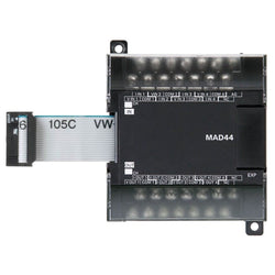
I/O expansion unit, 4 x analog inputs and 4 x analog outputs

Lexium 62 Double Drive 15 A - accessory kit included
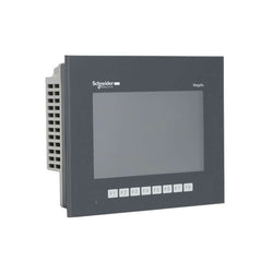
This Magelis GTO IP65 touchscreen operator interface (HMI) is supplied with 24V DC, has a 7" color TFT LCD display, 800 x 480 pixels (WVGA), 8 function keys and 96MB EPROM. This touchscreen operator interface (HMI) is ideal for optimized information and communication. Ideal for optimized information and communication with automation systems in industry and infrastructure such as compact machines, handling systems, food & beverage machines and pharmaceutical industry. The screen displays text messages, graphic objects and mimic diagrams, control and configuration of data. RS485 host port, ideal to supervise and control simple systems and machines. It is easily programmable with Vijeo Designer, with almost not coding needed.
Main
| Characteristic | Value(s) |
|---|---|
| Range of Product | Harmony GTO |
| Product or Component Type | Advanced touchscreen panel |
| Display colour | 65536 colours |
| Display size | 7 inch |
| Supply | External source |
| Control Button Type | 8 operation defined using Vijeo Designer push-button key F1...F8 |
| Operating System | Harmony |
| Battery type | Lithium internal RAM 100 days 5 day(s) 10 year(s) |
Complementary
| Characteristic | Value(s) |
|---|---|
| Terminal type | Touchscreen display |
| Display Type | Backlit colour TFT LCD |
| Display Resolution | 800 x 480 pixels WVGA |
| Touch sensitive zone | 1024 x 1024 |
| Touch panel | Resistive film, 1000000 cycles |
| Backlight lifespan | 50000 hours white 77 °F (25 °C) |
| Brightness | 16 levels by touch panel 16 levels by software |
| Character font | Taiwanese (traditional Chinese) ASCII Chinese (simplified Chinese) Japanese (ANK, Kanji) Korean |
| [Us] rated supply voltage | 24 V DC |
| Supply voltage limits | 19.2â¦28.8 V |
| Inrush current | 30 A |
| Maximum power consumption in W | 8 W when power is not supplied to external devices 5 W when backlight is OFF 5.5 W when backlight is dimmed 12 W |
| Local signalling | Status LED green, steady offline Status LED green, steady operating Status LED orange, flashing software starting up Status LED red, steady power supply (ON) Status LED clear, faded power supply (OFF) COM2 LED yellow, steady data is being transmitted COM2 LED yellow, faded no data transmission SD card LED green, steady card is inserted SD card LED green, faded card is not inserted or is not being accessed |
| Software designation | Vijeo Designer configuration software >= V6.1 |
| Memory description | Flash EPROM, 96 MB |
| Data backed up | 128 kB internal RAM SRAM) |
| Data storage equipment | SD card, <= 32 GB SDHC card, <= 32 GB |
| Downloadable protocols | Schneider Electric Modicon Modbus Schneider Electric Modicon Uni-TE Schneider Electric Modicon Modbus Plus Schneider Electric Modicon FIPWAY Mitsubishi Melsec third party protocols Omron Sysmac third party protocols Rockwell Automation Allen-Bradley third party protocols Siemens Simatic third party protocols Schneider Electric Modicon Modbus TCP |
| Integrated connection type | COM1 serial link SUB-D 9 RS232C 2400...115200 bps COM2 serial link RJ45 RS485 2400...115200 bps COM2 serial link RJ45 RS485 187.5 kbps Siemens MPI Ethernet RJ45 10BASE-T/100BASE-TX Ethernet RJ45 IEEE 802.3 USB 2.0 type A USB 2.0 type mini B |
| Product mounting | Flush mounting |
| Fixing mode | by 4 screw clamps |
| Front material | PPT |
| Enclosure Material | PPT |
| type of cooling | Natural convection |
| Width | 8.6 in (218 mm) |
| Height | 6.8 in (173 mm) |
| Depth | 2.4 in (60 mm) |
| Product Weight | 2.6 lb(US) (1.2 kg) |

This product is part of the Modicon M580 range, an offer of Programmable Automation Controllers (PAC) and safety Programmable Logic Controllers (PLC) with built-in Ethernet. This processor module offers a maximum of 8 rack configuration and 144 application specific channels. It is a processor module with a current consumption of 295mA at 24V DC. It supports 4096 discrete, 1024 analogue local I/O channels and 64 distributed equipment. It is integrated with Ethernet TCP/IP for service port, 2 Ethernet TCP/IP for device network, Ethernet for HSBY port and USB type mini B for connections. It offers 600000 hours of MTBF. It has 16 - 2 racks per remote drop for I/O station. It has an integrated RAM of 16MB for program, 2048kb for data, 10kb for system memory and expandable flash of 4GB for data storage. It is an IP20 rated product. It weighs 0.849kg. It is suitable for medium to large process applications. This product is certified by CE, Merchant Navy, UL, RCM, CSA, EAC. It meets EN 61131-2, EN 61000-6-4, EN 61000-6-2 and EN 61010-2-201 standards. The benefits of Modicon M580 are reduce time to market, improve reliability and sustainability, improve productivity with high performance and increase operating profitability due to improved access to data.
Main
| Characteristic | Value(s) |
|---|---|
| Range of Product | Modicon M580 |
| Product or Component Type | Processor module |
Complementary
| Characteristic | Value(s) |
|---|---|
| Number of racks | 8 |
| Local I/O processor capacity (discrete) | 4096 I/O |
| Local I/O processor capacity (analog) | 1024 I/O |
| Number of application specific channel (local rack) | 144 |
| Application specific I/O | Counter SSI encoder Motion control Accurate time stamping HART Serial link |
| Checks | Process control |
| Control channels | Programmable loops |
| Integrated connection type | 1 Ethernet TCP/IP service port 2 Ethernet TCP/IP device network USB type mini B |
| Number of remote I/O station | 16 - 2 remote drop |
| Number of distributed equipment | 64 |
| Communication module processor capacity | 16 AS-Interface module 4 Ethernet communication module |
| Communication Service | RIO scanner DIO scanner |
| Memory description | Expandable flash, 4 GB data storage Integrated RAM, 10 kB system memory Integrated RAM, 16 MB program Integrated RAM, 2048 kB data |
| Application structure | 2 auxiliary tasks 1 cyclic/periodic master task 1 periodic fast task 128 event tasks |
| Cybersecurity | Achilles certified DoS prevention IPSec SNMP logging Syslog protocol support Transport layer security Audit trail Embedded firewall Firmware signature Password protection Port hardening Secure communication (HTTPS) Security log |
| Number of instructions per ms | 30 Kinst/ms 65 % Boolean + 35 % fixed arithmetic 40 Kinst/ms 100 % Boolean |
| Current consumption | 295 mA 24 V DC |
| MTBF reliability | 775000 H |
| Marking | CE |
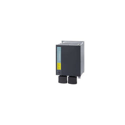
| Product | |
| Article Number (Market Facing Number) | 6SL31000BE280AB0 | 6SL31000BE280AB0 |
| Product Description | SINAMICS S120 ACTIVE INTERFACE MODULE FOR 80KW ACTIVE LINE MODULE INPUT: 3AC 380-480V, 50/60HZ |
| Product family | Ordering Data Overview |
| Product Lifecycle (PLM) | PM300:Active Product |
| Additional Product Information | |
| EAN | 4019169391443 |
| UPC | 662643432770 |
| Commodity Code | 85363030 |
| LKZ_FDB/ CatalogID | D21MC |
| Product Group | 9617 |
| Group Code | R220 |
| Country of origin | Germany |
| SCIP number | Not available |
| Delivery information | |
| Net Weight (lb) | 70.548 lb |
| Package size unit of measure | Not available |
| Packaging Quantity | 1 |
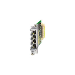
| Product | |
| Article Number (Market Facing Number) | 6SL30550AA002EB0 | 6SL30550AA002EB0 |
| Product Description | SINAMICS S120 CBE20 PROFINET module painted for connection to PROFINET IO with 4 RJ45 ports with switch functionality |
| Product family | Ordering Data Overview |
| Product Lifecycle (PLM) | PM300:Active Product |
| Additional Product Information | |
| EAN | 4042948672983 |
| UPC | 662643188936 |
| Commodity Code | 85176200 |
| LKZ_FDB/ CatalogID | D21MC |
| Product Group | 5675 |
| Group Code | R220 |
| Country of origin | Germany |
| SCIP number | Not available |
| Delivery information | |
| Net Weight (lb) | 0.258 lb |
| Package size unit of measure | Not available |
| Packaging Quantity | 1 |
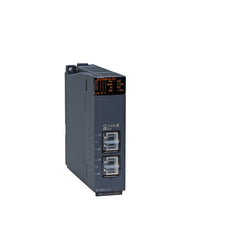
Plc Systemq Cc-Link Ie Field Master/Local Module, 1Gbps, Cat5E
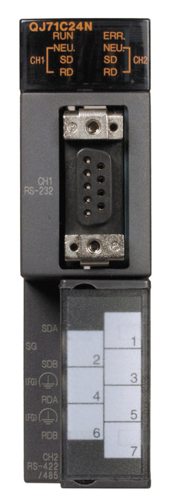
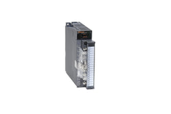
Plc Q Series Serial Communication Module Rs-232: 1 Port, Rs-422/485: 1 Port
Plc Q Series 8 Channel Analog Output Module Current; Isolated Ext Power Supply
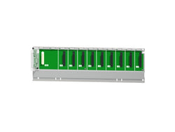
Plc Rack, Q Series, Base Unit, 8 Slots