
 1 year warranty


digital input module - 12I - 24V DC sink - 1 wire
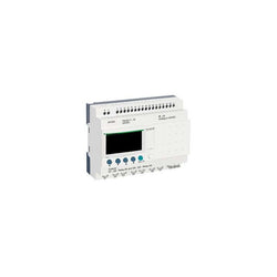
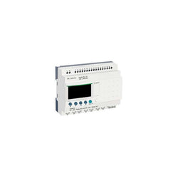
modular smart relay Zelio Logic - 26 I O - 24 V DC - clock - display

Main
| Characteristic | Value(s) |
|---|---|
| Range of Product | Harmony XBTGT |
| Product or Component Type | Advanced touchscreen panel |
| Display Type | Backlit colour TFT LCD |
| Display colour | 65536 colours |
| Display Resolution | 800 x 600 pixels SVGA |
| Display size | 12.1 inch |
| Software Type | Configuration software |
| Software Designation | Vijeo Designer |
| Operating System | Harmony |
| Processor name | CPU RISC |
| Processor frequency | 266 MHz |
| Memory description | 512 KB SRAM back up of data lithium battery 32 MB flash EPROM application memory |
| Integrated connection type | RJ45 COM2 serial link RS485 <= 187.5 kbit/s Siemens MPI (187.5 kbits/s) male SUB-D 9 COM1 serial link RS232C/RS422/RS485 <= 115.2 kbits/s removable screw terminal block power supply RJ45 Ethernet TCP/IP 3 removable screw terminal block digital output removable screw terminal block audio output removable screw terminal block digital input 2 USB type A master port (V1.1) |
| Resistance to electrostatic discharge | 6 kV IEC 61000-4-2 level 3 |
| Cut-out dimensions | 301.5 (+ 1/- 0) x 227.5 (+ 1/- 0) mm |
Complementary
| Characteristic | Value(s) |
|---|---|
| Touch sensitive zone | 1024 x 1024 |
| Touch panel | Analogue |
| Backlight lifespan | 50000 hours |
| Brightness | 8 levels via touch panel |
| Character font | Chinese (simplified Chinese) Korean ASCII (European characters) Japanese (ANK, Kanji) Taiwanese (traditional Chinese) |
| [Us] rated supply voltage | 24 V DC |
| Supply | External source |
| Supply voltage limits | 19.2â¦28.8 V |
| Inrush current | 30 A |
| Power Consumption in W | 30 W |
| Local signalling | 1 LED (green or orange) for normal operation or backlighting faulty |
| Number of pages | Limited by internal memory capacity |
| Downloadable protocols | Telemecanique Modicon FIPWAY Telemecanique Modicon Modbus Plus Telemecanique Modicon Modbus TCP Telemecanique Modicon Modbus Mitsubishi Melsec third party protocols Omron Sysmac third party protocols Rockwell Automation Allen-Bradley third party protocols Siemens Simatic third party protocols Telemecanique Modicon Uni-TE |
| Realtime clock | Built-in |
| Data storage equipment | 1 Compact Flash card >= 1 GB |
| Use of slot | For 1 fieldbus communication card (Device Net, Profibus DP) |
| Port Ethernet | 10BASE-T/100BASE-TX |
| Product mounting | Flush mounting |
| Fixing Mode | By 4 spring clips By 4 screw clamps |
| Front material | Aluminium alloy |
| Enclosure Material | PPT |
| Marking | CE |
| Width | 12.3 in (313 mm) |
| Height | 9.4 in (239 mm) |
| Depth | 2.2 in (56 mm) |
| Product Weight | 6.6 lb(US) (3 kg) |
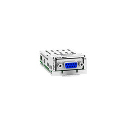
This Schneider Electric Altivar Profibus DP communication module has 1 x 9-way female SUB-D connector. It complies with PROFIBUS DP V1 standard. This communication module enables integration of your drive in your Profibus process control network. It is simple to install and remove from Altivar drives thanks to its modular withdrawable design. It is compatible with Altivar Process ATV600 (ATV630, ATV650)Altivar Process ATV900 (ATV930, ATV950), Lexium 32, Altivar Easy 610, Altivar 32, Altivar Machine ATV340 and Altivar Machine ATV320. Removable module allows last minute decisions on drive communication protocol, facilitates installation project management. It weighs 140g.
Main
| Characteristic | Value(s) |
|---|---|
| Range of Product | Altivar |
| Product or Component Type | Communication module |
| Accessory / separate part category | Communication accessories |
Complementary
| Characteristic | Value(s) |
|---|---|
| Product Compatibility | Lexium 32M |
| Range compatibility | Altivar 32 Altivar Machine ATV340 except Sercos drives Altivar Easy 610 Lexium 32 Altivar Process ATV900 Altivar Process ATV600 Altivar Machine ATV320 Altivar Process Modular |
| Communication Port Protocol | Profibus DP V1 |
| Electrical connection | 1 female connector SUB-D 9 |
| Transmission Rate | 9.6 kbps...12 Mbps |
| Addressing | 1...126 configurable by graphic terminal/SoMove software Configuration settings |
| Communication service | 4 configurable telegrams Mapping of the process data from the master Parameters management compliant with PROFIdrive V4.1 Several DP V1 messaging modes Drive profile native ATV32 IEC 61800-7-201 (CiA 402) |
| Display type | 1 LED RUN 1 LED bus fault (BF) |
| diagnostic function | Diagnostic data with VSD status Host drive handled from two masters (MS0 and MS1) Standard identification and maintenance requests |
| Bus profile | PROFIdrive CiA 402 |

Discrete input module, Modicon TM3, 16 inputs (spring) 24 VDC

Ethercat 2 x RJ45 communication module

Analog output module, Modicon TM3, 4 outputs (spring) 24 VDC

limit switch XCKMR - stay put crossed rods lever 6mm - 2x(2 NC) - slow - M20
Main
| Characteristic | Value(s) |
|---|---|
| Range of Product | Modicon Premium Automation platform |
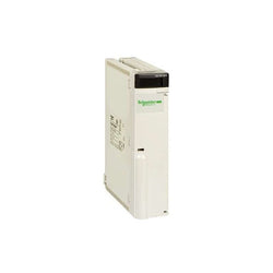
| Product or Component Type | Power supply module |
Complementary
| Characteristic | Value(s) |
|---|---|
| Primary voltage | 100...240 V AC 85...264 V |
| Network Frequency | 50/60 Hz |
| Network frequency limits | 47â¦63 Hz |
| Input current | 300 mA 240 V 500 mA 100 V |
| Inrush current | 37 A 100 V 75 A 240 V |
| I²t on activation | 0.63 A².s 100 V 2.6 A².s 240 V |
| It on activation | 0.034 A.s 100 V 0.067 A.s 240 V |
| Protection type | Internal fuse 4 A 5 x 20 mm time-delayed primary circuit Overload protection secondary circuit Overvoltage protection secondary circuit Short-circuit protection secondary circuit |
| Total useful secondary power | 26 W |
| Secondary power | 15 W 24 V DC 25 W 5 V DC |
| Current at secondary voltage | 0.5 A 24 V DC sensor power supply 0.6 A 24 V DC relay power supply 5 A 5 V DC |
| Insulation resistance | >= 100 MOhm primary/ground >= 100 MOhm primary/secondary |
| Marking | CE |
| Local signalling | 1 LED (green) for presence of sensor voltage (24V) 1 LED (green) for presence of voltages (OK) 1 LED (red) for battery fault (BAT) |
| Module format | Standard |
| Product Weight | 1.12 lb(US) (0.51 kg) |

Unity processor - 8 racks (12 slots) / 16 racks (4/6/8 slots) - 1650 mA, 5 V DC
Main
| Characteristic | Value(s) |
|---|---|
| Range of Product | Modicon Premium Automation platform |
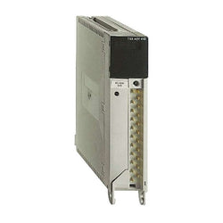
| Product or Component Type | Analog output module |
| Analogue output number | 4 |
| Analogue output type | Current 0...20 mA Current 4...20 mA Voltage +/- 10 V |
| Analog/digital conversion | 11 bits + sign |
Complementary
| Characteristic | Value(s) |
|---|---|
| Conversion time | 2.5 ms |
| Measurement resolution | 10.25 µA 0...20 mA 10.25 µA 4...20 mA 5.12 mV +/- 10 V |
| Electrical Connection | Screw terminal block |
| Measurement error | 0.45 % of full scale +/- 10 V 25 °C 0.52 % of full scale 0...20 mA 25 °C 0.52 % of full scale 4...20 mA 25 °C 0.75 % of full scale +/- 10 V 0...60 °C 0.98 % of full scale 0...20 mA 0...60 °C 0.98 % of full scale 4...20 mA 0...60 °C |
| Isolation between channels | 1500 Vrms |
| Isolation between channels and bus | 1500 Vrms |
| Isolation between channels and ground | 500 V |
| Protection Type | Overload protection Short-circuit protection |
| Output voltage limits | <= 30 V |
| Load impedance ohmic | < 600 Ohm 0...20 mA < 600 Ohm 4...20 mA > 1000 Ohm +/- 10 V |
| Maximum load inductance | 300 µH |
| Maximum load capacitance | 0.1 µF |
| Marking | CE |
| Current consumption | 900 mA 5 V DC |
| Module format | Standard |
| Terminals description PLC n°1 | (14)OUT_ANA_SHIELD# (19)OUT_ANA_SHIELD# (18)OUT_ANA_CUR#3 (1)OUT_ANA_VOLT#0 (5)OUT_ANA_SHIELD# (16)OUT_ANA_VOLT#3 (15)OUT_ANA_SHIELD# (11)OUT_ANA_VOLT#2 (12)OUT_ANA_COM#2 (20)OUT_ANA_SHIELD# (6)OUT_ANA_VOLT#1 (7)OUT_ANA_COM#1 (2)OUT_ANA_COM#0 (13)OUT_ANA_CUR#2 (4)OUT_ANA_SHIELD# (8)OUT_ANA_CUR#1 (9)OUT_ANA_SHIELD# (3)OUT_ANA_CUR#0 (17)OUT_ANA_COM#3 (10)OUT_ANA_SHIELD# |
| Product Weight | 0.77 lb(US) (0.35 kg) |
modular smart relay Zelio Logic - 26 I O - 100..240 V AC - clock - display
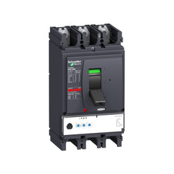
This Compact NSX400N is a complete 3P 3d fixed circuit breaker designed to optimize space and breaking capacity. It is an optimal choice for all standard and specific applications. The breaking capacity (Icu) is 50kA rms at 415VAC 50/60Hz. The operational voltage is 690VAC 50/60Hz. This product embeds an electronic Micrologic 2.3 trip unit, with 400A rating. Micrologic 2.3 trip unit provides adjustable long time and short time protections, and a fixed instantaneous protection. This 3 poles version (140mm x 255mm x 110mm) comes with a variety of optional functions and accessories. It is compliant with international standards (IEC 60947), CCC, EAC and marine specifications. Compact NSX400N is part of Schneider Electric EcoStruxure Power architecture.
Main
| Characteristic | Value(s) |
|---|---|
| Range | ComPact |
| product name | ComPact NSX |
| Range of product | ComPact NSX400...630 |
| Device short name | NSX400N |
| Product or component type | Circuit breaker |
| Device application | Distribution |
| Number of poles | 3P |
| Protected poles description | 3t |
| [In] rated current | 400 A at 40 °C |
| [Ue] rated operational voltage | 690 V AC 50/60 Hz |
| Network type | AC |
| Network frequency | 50/60 Hz |
| Suitability for isolation | Yes conforming to EN/IEC 60947-2 |
| Utilisation category | Category A |
| [Icu] rated ultimate short-circuit breaking capacity | 85 kA at 240 V AC 50/60 Hz conforming to UL 508 22 kA Icu at 525 V AC 50/60 Hz conforming to IEC 60947-2 85 kA Icu at 220/240 V AC 50/60 Hz conforming to IEC 60947-2 10 kA Icu at 660/690 V AC 50/60 Hz conforming to IEC 60947-2 30 kA Icu at 500 V AC 50/60 Hz conforming to IEC 60947-2 20 kA at 600 V AC 50/60 Hz conforming to UL 508 50 kA at 480 V AC 50/60 Hz conforming to UL 508 50 kA Icu at 380/415 V AC 50/60 Hz conforming to IEC 60947-2 42 kA Icu at 440 V AC 50/60 Hz conforming to IEC 60947-2 |
| Performance level | N 50 kA 415 V AC |
| Trip unit name | MicroLogic 2.3 |
| Trip unit technology | Electronic |
| Trip unit protection functions | LSoI |
| control type | Toggle |
| Circuit breaker mounting mode | Fixed |
Complementary
| Characteristic | Value(s) |
|---|---|
| [Ui] rated insulation voltage | 800 V AC 50/60 Hz |
| [Uimp] rated impulse withstand voltage | 8 kV |
| [Ics] rated service short-circuit breaking capacity | 11 kA at 525 V AC 50/60 Hz conforming to IEC 60947-2 85 kA at 220/240 V AC 50/60 Hz conforming to IEC 60947-2 10 kA at 660/690 V AC 50/60 Hz conforming to IEC 60947-2 50 kA at 380/415 V AC 50/60 Hz conforming to IEC 60947-2 30 kA at 500 V AC 50/60 Hz conforming to IEC 60947-2 42 kA at 440 V AC 50/60 Hz conforming to IEC 60947-2 |
| Mechanical durability | 15000 cycles |
| Electrical durability | 3000 cycles at 690 V In 6000 cycles at 690 V In/2 6000 cycles at 440 V In 12000 cycles at 440 V In/2 |
| Mounting support | Backplate |
| Upside connection | Front |
| Downside connection | Front |
| Connection pitch | 45 mm |
| Protection type | L : for overload protection (long time) So : for short time short-circuit protection with fixed delay I : for instantaneous short-circuit protection |
| Trip unit rating | 400 A at 40 °C |
| Long-time pick-up adjustment type Ir (thermal protection) | Adjustable 9 settings |
| [Ir] long-time protection pick-up adjustment range | 160...400 A |
| Long-time protection delay adjustment type tr | Fixed |
| [tr] long-time protection delay adjustment range | 16 s at 6 x Ir |
| Thermal memory | 20 minutes before and after tripping |
| Short-time protection pick-up adjustment type Isd | Adjustable 9 settings |
| [Isd] Short-time protection pick-up adjustment range | 1.5...10 x Ir |
| Short-time protection delay adjustment type tsd | Fixed |
| Instantaneous protection pick-up adjustment type Ii | Fixed |
| [Ii] instantaneous protection pick-up adjustment range | 4800 A |
| Earth-leakage protection | Without |
| Zone selective interlocking ZSI | Without |
| Number of slots for electrical auxiliaries | 6 slot(s) |
| Local signalling | Flashing LED (green) for ready to operate LED 105 % Ir (red) for overload LED 90 % Ir (orange) for overload |
| Width (W) | 140 mm |
| Height (H) | 255 mm |
| Depth (D) | 110 mm |
| Product weight | 6.05 kg |
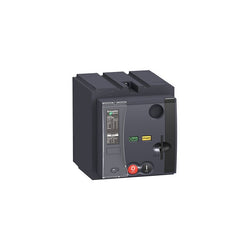
motor mechanism, MT 400-630, Compact NSX400/630, PowerPact Multistandard L, 220 to 240 VAC 50/60 Hz, 208 to 277 VAC 60 Hz

circuit breaker ComPact NSX250F, 36 kA at 415 VAC, TMD trip unit 250 A, 3 poles 3d

switch disconnector Compact NSX250NA, 3 poles, 250 A, AC22A, AC23A

Ethernet module M340 - flash memory card - 1 x RJ45 10/100

This analog mixed I/O module is part of the Modicon X80 modules. It has 4 non-isolated inputs (14/12 bits) and 2 non-isolated outputs (12 bits). It offers different ranges of voltage or current for each of the inputs / outputs depending on configuration choice. It occupies a single slot on the rack and it has a case which provides IP 20 protection of the electronics.
Main
| Characteristic | Value(s) |
|---|---|
| Range of Product | Modicon X80 |
| Product or Component Type | Mixed analog I/O module |
| Electrical connection | 20 ways 1 connector |
| Isolation between channels | Non isolated |
| Input level | High level |
| Analogue input number | 4 |
| Analogue input type | Current 0...20 mA Current 4...20 mA Voltage +/- 10 V Voltage 0...10 V Voltage 0...5 V Voltage 1...5 V |
Complementary
| Characteristic | Value(s) |
|---|---|
| Analogue input resolution | 12 bits 0...20 mA 12 bits 0...5 V 12 bits 1...5 V 12 bits 4...20 mA 13 bits 0...10 V 14 bits +/- 10 V |
| Permitted overload on inputs | +/- 30 mA 0...20 mA +/- 30 mA 4...20 mA +/- 30 V +/- 10 V +/- 30 V 0...10 V +/- 30 V 0...5 V +/- 30 V 1...5 V |
| Input impedance | 250 Ohm |
| Precision of internal conversion resistor | 0.1 % - 15 ppm/°C |
| Type of filter | First order digital filtering by firmware |
| Fast read cycle time | 1 ms + 1 ms x number of channels used |
| Nominal read cycle time | 5 ms for 4 channels |
| Measurement error | 0.25 % of full scale 0...20 mA 25 °C output 0.25 % of full scale 4...20 mA 25 °C output <= 0.35 % of full scale +/- 10 V 0...60 °C input <= 0.35 % of full scale 0...10 V 0...60 °C input <= 0.35 % of full scale 0...5 V 0...60 °C input <= 0.35 % of full scale 1...5 V 0...60 °C input <= 0.5 % of full scale 0...20 mA 0...60 °C input <= 0.5 % of full scale 4...20 mA 0...60 °C input <= 0.6 % of full scale +/- 10 V 0...60 °C output <= 0.6 % of full scale 0...20 mA 0...60 °C output <= 0.6 % of full scale 4...20 mA 0...60 °C output 0.25 % of full scale +/- 10 V 25 °C output 0.25 % of full scale +/- 10 V 25 °C input 0.25 % of full scale 0...10 V 25 °C input 0.25 % of full scale 0...5 V 25 °C input 0.25 % of full scale 1...5 V 25 °C input 0.35 % of full scale 0...20 mA 25 °C input 0.35 % of full scale 4...20 mA 25 °C |
| Temperature drift | 100 ppm/°C +/- 10 V output 100 ppm/°C 0...20 mA output 100 ppm/°C 4...20 mA output 30 ppm/°C +/- 10 V input 30 ppm/°C 0...10 V input 30 ppm/°C 0...5 V input 30 ppm/°C 1...5 V input 50 ppm/°C 0...20 mA input 50 ppm/°C 4...20 mA input |
| Recalibration | Factory calibrated on outputs Internal on inputs |
| Minimum crosstalk attenuation | 70 dB |
| EMI/RFI Noise rejection (100 kHz to 10 MHz) | 80 dB |
| Isolation voltage | 1400 V DC between channels and ground 1400 V DC between channels and bus 750 V DC between group of I/O channels |
| Output level | High level |
| Analogue output number | 2 |
| Analogue output type | Current 0...20 mA Current 4...20 mA Voltage +/- 10 V |
| Analogue output resolution | 11 bits, 0...20 mA 11 bits, 4...20 mA 12 bits, +/- 10 V |
| Conversion time | <= 2 ms |
| Maximum conversion value | +/- 11.25 V +/- 10 V output +/- 11.25 V +/- 10 V input 0...30 mA 0...20 mA input 0...30 mA 4...20 mA input +/- 11.25 V 0...10 V input +/- 11.25 V 0...5 V input +/- 11.25 V 1...5 V input 0...24 mA 0...20 mA output 0...24 mA 4...20 mA output |
| Fallback mode | Predefined Configurable |
| MTBF reliability | 1400000 H |
| Operating altitude | 0...6561.68 ft (0...2000 m) 2000...5000 m with derating factor |
| Status LED | 1 LED (Green) RUN 1 LED per channel (Green) channel diagnostic 1 LED (Red) ERR 1 LED (Red) I/O |
| Product Weight | 0.342 lb(US) (0.155 kg) |
| Power consumption in W | 2.6 W 24 V DC typical 3.2 W 24 V DC maximum 0.35 W 3.3 V DC typical 0.48 W 3.3 V DC maximum |
| Current consumption | 240 mA 3.3 V DC |

Main
| Characteristic | Value(s) |
|---|---|
| Range of Product | Altivar 71 |
| Product or Component Type | Variable speed drive |
| Product Specific Application | Complex, high-power machines |
| Component name | ATV71 |
| Motor power kW | 55 kW, 3 phase 380...480 V |
| Maximum Horse Power Rating | 75 hp, 3 phase 380...480 V |
| Maximum motor cable length | 328.08 ft (100 m) shielded cable 656.2 ft (200 m) unshielded cable |
| power supply voltage | 380...480 V - 15...10 % |
| Phase | 3 phase |
| Line current | 101 A 480 V 3 phase 55 kW / 75 hp 120 A 380 V 3 phase 55 kW / 75 hp |
| EMC filter | Integrated |
| Assembly style | With heat sink |
| Apparent power | 79 kVA 380 V 3 phase 55 kW / 75 hp |
| Prospective line Isc | 22 kA 3 phase |
| Nominal output current | 116 A 2.5 kHz 380 V 3 phase 55 kW / 75 hp 96 A 2.5 kHz 460 V 3 phase 55 kW / 75 hp |
| Maximum transient current | 174 A 60 s 3 phase 55 kW / 75 hp 191 A 2 s 3 phase 55 kW / 75 hp |
| Output frequency | 0.1â¦500 Hz |
| Nominal switching frequency | 2.5 kHz |
| Switching frequency | 1...16 kHz adjustable 2.5...16 kHz with derating factor |
| Asynchronous motor control profile | Sensorless flux vector control (SFVC) (voltage or current vector) Voltage/frequency ratio (2 or 5 points) Flux vector control (FVC) with sensor (current vector) ENA (Energy adaptation) system for unbalanced loads |
| Type of polarization | No impedance Modbus |
Complementary
| Characteristic | Value(s) |
|---|---|
| Product destination | Asynchronous motors Synchronous motors |
| power supply voltage limits | 323â¦528 V |
| power supply frequency | 50...60 Hz - 5...5 % |
| power supply frequency limits | 47.5...63 Hz |
| Speed range | 1â¦100 asynchronous motor in open-loop mode, without speed feedback 1â¦1000 asynchronous motor in closed-loop mode with encoder feedback 1â¦50 synchronous motor in open-loop mode, without speed feedback |
| Speed accuracy | +/- 0.01 % of nominal speed in closed-loop mode with encoder feedback 0.2 Tn to Tn +/- 10 % of nominal slip without speed feedback 0.2 Tn to Tn |
| Torque accuracy | +/- 15 % in open-loop mode, without speed feedback +/- 5 % in closed-loop mode with encoder feedback |
| Transient overtorque | 170 % +/- 10 % 60 s every 10 minutes 220 % +/- 10 % 2 s |
| Braking torque | <= 150 % with braking or hoist resistor 30 % without braking resistor |
| Synchronous motor control profile | Vector control without speed feedback |
| Regulation loop | Adjustable PI regulator |
| Motor slip compensation | Suppressable Adjustable Automatic whatever the load Not available in voltage/frequency ratio (2 or 5 points) |
| diagnostic | 1 LED (red) for drive voltage |
| Output voltage | <= power supply voltage |
| Insulation | Electrical between power and control |
| type of cable for mounting in an enclosure | With a NEMA Type1 kit 3 UL 508 cable 104 °F (40 °C), copper 75 °C / PVC With an IP21 or an IP31 kit 3 IEC cable 104 °F (40 °C), copper 70 °C / PVC Without mounting kit 1 IEC cable 113 °F (45 °C), copper 70 °C / PVC Without mounting kit 1 IEC cable 113 °F (45 °C), copper 90 °C / XLPE/EPR |
| Electrical connection | Terminal 2.5 mm², AWG 14 AI1-/AI1+, AI2, AO1, R1A, R1B, R1C, R2A, R2B, LI1...LI6, PWR) Terminal 150 mm² L1/R, L2/S, L3/T, U/T1, V/T2, W/T3, PC/-, PO, PA/+, PA, PB) |
| Tightening torque | 5.3 lbf.in (0.6 N.m) AI1-/AI1+, AI2, AO1, R1A, R1B, R1C, R2A, R2B, LI1...LI6, PWR) 362.9 lbf.in (41 N.m), 360 lb.in L1/R, L2/S, L3/T, U/T1, V/T2, W/T3, PC/-, PO, PA/+, PA, PB) |
| Supply | Internal supply for reference potentiometer (1 to 10 kOhm) 10.5 V DC +/- 5 %, <10 mA overload and short-circuit protection Internal supply 24 V DC 21â¦27 V), <200 mA overload and short-circuit protection |
| Analogue input number | 2 |
| Analogue input type | AI1-/Al1+ bipolar differential voltage +/- 10 V DC 24 V max 11 bits + sign AI2 software-configurable current 0...20 mA 242 Ohm 11 bits AI2 software-configurable voltage 0...10 V DC 24 V max 30000 Ohm 11 bits |
| input sampling time | 2 ms +/- 0.5 ms AI1-/Al1+) - analog 2 ms +/- 0.5 ms Al2) - analog 2 ms +/- 0.5 ms LI1...LI5) - discrete 2 ms +/- 0.5 ms LI6)if configured as logic input - discrete |
| Response time | <= 100 ms in STO (Safe Torque Off) AO1 2 ms +/- 0.5 ms analog R1A, R1B, R1C 7 ms +/- 0.5 ms discrete R2A, R2B 7 ms +/- 0.5 ms discrete |
| absolute accuracy precision | +/- 0.6 % AI1-/Al1+) for a temperature variation 60 °C +/- 0.6 % AI2) for a temperature variation 60 °C +/- 1 % AO1) for a temperature variation 60 °C |
| Linearity error | +/- 0.15 % of maximum value AI1-/Al1+, AI2) +/- 0.2 % AO1) |
| Analogue output number | 1 |
| Analogue output type | AO1 software-configurable logic output 10 V 20 mA AO1 software-configurable current 0...20 mA 500 Ohm 10 bits AO1 software-configurable voltage 0...10 V DC 470 Ohm 10 bits |
| Discrete output number | 2 |
| Discrete output type | Configurable relay logic R1A, R1B, R1C) NO/NC - 100000 cycles Configurable relay logic R2A, R2B) NO - 100000 cycles |
| Minimum switching current | 3 mA 24 V DC configurable relay logic |
| Maximum switching current | R1, R2 2 A 250 V AC inductive, cos phi = 0.4 R1, R2 2 A 30 V DC inductive, cos phi = 0.4 R1, R2 5 A 250 V AC resistive, cos phi = 1 R1, R2 5 A 30 V DC resistive, cos phi = 1 |
| Discrete input number | 7 |
| Discrete input type | LI1...LI5 programmable 24 V DC level 1 PLC 3500 Ohm LI6 switch-configurable 24 V DC level 1 PLC 3500 Ohm LI6 switch-configurable PTC probe 0â¦6 1500 Ohm PWR safety input 24 V DC 1500 Ohm ISO 13849-1 level d |
| Discrete input logic | Negative logic (sink) LI1...LI5), > 16 V, < 10 V Positive logic (source) LI1...LI5), < 5 V, > 11 V Negative logic (sink) LI6)if configured as logic input, > 16 V, < 10 V Positive logic (source) LI6)if configured as logic input, < 5 V, > 11 V |
| Acceleration and deceleration ramps | Automatic adaptation of ramp if braking capacity exceeded, by using resistor S, U or customized Linear adjustable separately from 0.01 to 9000 s |
| Braking to standstill | By DC injection |
| Protection type | Against exceeding limit speed drive Against input phase loss drive Break on the control circuit drive Input phase breaks drive Line supply overvoltage drive Line supply undervoltage drive Overcurrent between output phases and earth drive Overheating protection drive Overvoltages on the DC bus drive Short-circuit between motor phases drive Thermal protection drive Motor phase break motor Power removal motor Thermal protection motor |
| Insulation resistance | > 1 mOhm 500 V DC for 1 minute to earth |
| Frequency resolution | Analog input 0.024/50 Hz Display unit 0.1 Hz |
| Communication Port Protocol | CANopen Modbus |
| Connector type | 1 RJ45 on front face)Modbus 1 RJ45 on terminal)Modbus Male SUB-D 9 on RJ45CANopen |
| Physical interface | 2-wire RS 485 Modbus |
| Transmission frame | RTU Modbus |
| Transmission rate | 4800 bps, 9600 bps, 19200 bps, 38.4 Kbps Modbus on terminal 9600 bps, 19200 bps Modbus on front face 20 kbps, 50 kbps, 125 kbps, 250 kbps, 500 kbps, 1 Mbps CANopen |
| Data format | 8 bits, 1 stop, even parity Modbus on front face 8 bits, odd even or no configurable parity Modbus on terminal |
| Number of addresses | 1â¦127 CANopen 1â¦247 Modbus |
| Method of access | Slave CANopen |
| Marking | CE |
| Operating position | Vertical +/- 10 degree |
| Height | 24.8 in (630 mm) |
| Depth | 11.4 in (290 mm) |
| Width | 12.6 in (320 mm) |
| Product Weight | 97.003 lb(US) (44 kg) |
| Functionality | Full |
| Specific application | Other applications |
| Option card | Communication card CC-Link Controller inside programmable card Communication card DeviceNet Communication card EtherNet/IP Communication card Fipio I/O extension card Communication card Interbus-S Interface card for encoder Communication card Modbus Plus Communication card Modbus TCP Communication card Modbus/Uni-Telway Overhead crane card Communication card Profibus DP Communication card Profibus DP V1 |

Variable Speed Drive Altivar 71 - 15kW-20hp - 480V - with EMC filter whitout Graphic Terminal

Main
| Characteristic | Value(s) |
|---|---|
| Range of Product | Altivar 61 |
| Product or Component Type | Variable speed drive |
| Product Specific Application | Pumping and ventilation machine |
| Component name | ATV61 |
| Motor power kW | 7.5 kW, 3 phase 380...480 V |
| Maximum Horse Power Rating | 10 hp, 3 phase 380...480 V |
| power supply voltage | 380...480 V - 15...10 % |
| supply number of phases | 3 phase |
| Line current | 22.2 A 480 V 3 phase 7.5 kW / 10 hp 27 A 380 V 3 phase 7.5 kW / 10 hp |
| EMC filter | Level 3 EMC filter |
| Variant | Without remote graphic terminal |
| Assembly style | With heat sink |
| Apparent power | 17.8 kVA 380 V 3 phase 7.5 kW / 10 hp |
| maximum prospective line Isc | 22 kA 3 phase |
| Maximum transient current | 21.1 A 60 s, 3 phase |
| Nominal switching frequency | 12 kHz |
| Switching frequency | 1...16 kHz adjustable 12...16 kHz with derating factor |
| asynchronous motor control | Flux vector control without sensor, standard Voltage/frequency ratio, 2 points Voltage/frequency ratio - Energy Saving, quadratic U/f Voltage/frequency ratio, 5 points |
| Synchronous motor control profile | Vector control without sensor, standard |
| Communication Port Protocol | CANopen Modbus |
| Type of polarization | No impedance Modbus |
| Option card | Communication card APOGEE FLN Communication card BACnet Communication card CC-Link Controller inside programmable card Communication card DeviceNet Communication card EtherNet/IP Communication card Fipio I/O extension card Communication card Interbus-S Communication card LonWorks Communication card METASYS N2 Communication card Modbus Plus Communication card Modbus TCP Communication card Modbus/Uni-Telway Multi-pump card Communication card Profibus DP Communication card Profibus DP V1 |
Complementary
| Characteristic | Value(s) |
|---|---|
| Product destination | Asynchronous motors Synchronous motors |
| power supply voltage limits | 323â¦528 V |
| power supply frequency | 50...60 Hz - 5...5 % |
| power supply frequency limits | 47.5...63 Hz |
| Continuous output current | 14 A 12 kHz, 460 V - 3 phase 17.6 A 12 kHz, 380 V - 3 phase |
| Output frequency | 0.1â¦599 Hz |
| Speed range | 1â¦100 in open-loop mode, without speed feedback |
| Speed accuracy | +/- 10 % of nominal slip 0.2 Tn to Tn without speed feedback |
| Torque accuracy | +/- 15 % in open-loop mode, without speed feedback |
| Transient overtorque | 130 % of nominal motor torque +/- 10 % 60 s |
| Braking torque | <= 125 % with braking resistor 30 % without braking resistor |
| Regulation loop | Frequency PI regulator |
| Motor slip compensation | Not available in voltage/frequency ratio (2 or 5 points) Can be suppressed Automatic whatever the load Adjustable |
| diagnostic | 1 LED (red) for drive voltage |
| Output voltage | <= power supply voltage |
| electrical isolation | Between power and control terminals |
| type of cable for mounting in an enclosure | With an IP21 or an IP31 kit 3 IEC cable 104 °F (40 °C), copper 70 °C / PVC With UL Type 1 kit 3 UL 508 cable 104 °F (40 °C), copper 75 °C / PVC Without mounting kit 1 IEC cable 113 °F (45 °C), copper 70 °C / PVC Without mounting kit 1 IEC cable 113 °F (45 °C), copper 90 °C / XLPE/EPR |
| Electrical connection | Terminal 2.5 mm² / AWG 14 AI1-/AI1+, AI2, AO1, R1A, R1B, R1C, R2A, R2B, LI1...LI6, PWR) Terminal 6 mm² / AWG 8 L1/R, L2/S, L3/T, U/T1, V/T2, W/T3, PC/-, PO, PA/+, PA, PB) |
| Tightening torque | 5.3 lbf.in (0.6 N.m) AI1-/AI1+, AI2, AO1, R1A, R1B, R1C, R2A, R2B, LI1...LI6, PWR) 26.6 lbf.in (3 N.m), 26.5 lb.in L1/R, L2/S, L3/T, U/T1, V/T2, W/T3, PC/-, PO, PA/+, PA, PB) |
| Supply | Internal supply for reference potentiometer (1 to 10 kOhm) 10.5 V DC, +/- 5 %, <10 mA overload and short-circuit protection Internal supply 24 V DC 21â¦27 V), <200 mA overload and short-circuit protection External supply 24 V DC 19â¦30 V) |
| Analogue input number | 2 |
| Analogue input type | AI1-/Al1+ bipolar differential voltage +/- 10 V DC 24 V max 11 bits + sign AI2 software-configurable current 0...20 mA 242 Ohm 11 bits AI2 software-configurable voltage 0...10 V DC 24 V max 30000 Ohm 11 bits |
| sampling time | 2 ms +/- 0.5 ms AI1-/Al1+) - analog input 2 ms +/- 0.5 ms Al2) - analog input 2 ms +/- 0.5 ms AO1) - analog output 2 ms +/- 0.5 ms LI1...LI5) - discrete input 2 ms +/- 0.5 ms LI6)if configured as logic input - discrete input |
| absolute accuracy precision | +/- 0.6 % AI1-/Al1+) for a temperature variation 60 °C +/- 0.6 % AI2) for a temperature variation 60 °C +/- 1 % AO1) for a temperature variation 60 °C |
| Linearity error | +/- 0.15 % of maximum value AI1-/Al1+) +/- 0.15 % of maximum value AI2) +/- 0.2 % AO1) |
| Analogue output number | 1 |
| Analogue output type | AO1 software-configurable current 0...20 mA 500 Ohm 10 bits AO1 software-configurable voltage 0...10 V DC 470 Ohm 10 bits AO1 software-configurable logic output 10 V, 20 mA |
| Discrete output number | 2 |
| Discrete output type | Configurable relay logic R1A, R1B, R1C) NO/NC - 100000 cycles Configurable relay logic R2A, R2B) NO - 100000 cycles |
| maximum response time | <= 100 ms in STO (Safe Torque Off) R1A, R1B, R1C <= 7 ms +/- 0.5 ms R2A, R2B <= 7 ms +/- 0.5 ms |
| Minimum switching current | 3 mA 24 V DC configurable relay logic |
| Maximum switching current | R1, R2 2 A 250 V AC inductive, cos phi = 0.4 7 ms R1, R2 2 A 30 V DC inductive, cos phi = 0.4 7 ms R1, R2 5 A 250 V AC resistive, cos phi = 1 0 ms R1, R2 5 A 30 V DC resistive, cos phi = 1 0 ms |
| Discrete input number | 7 |
| Discrete input type | Programmable LI1...LI5) 24 V DC <= 30 V)level 1 PLC - 3500 Ohm Switch-configurable LI6) 24 V DC <= 30 V)level 1 PLC - 3500 Ohm Switch-configurable PTC probe LI6)0â¦6 - 1500 Ohm Safety input PWR) 24 V DC <= 30 V) - 1500 Ohm |
| Discrete input logic | Negative logic (sink) LI1...LI5), > 16 V, < 10 V Positive logic (source) LI1...LI5), < 5 V, > 11 V Negative logic (sink) LI6)if configured as logic input, > 16 V, < 10 V Positive logic (source) LI6)if configured as logic input, < 5 V, > 11 V |
| Acceleration and deceleration ramps | Automatic adaptation of ramp if braking capacity exceeded, by using resistor S, U or customized Linear adjustable separately from 0.01 to 9000 s |
| Braking to standstill | By DC injection |
| Protection type | Against exceeding limit speed drive Against input phase loss drive Break on the control circuit drive Input phase breaks drive Line supply overvoltage drive Line supply undervoltage drive Overcurrent between output phases and earth drive Overheating protection drive Overvoltages on the DC bus drive Power removal drive Short-circuit between motor phases drive Thermal protection drive Motor phase break motor Power removal motor Thermal protection motor |
| Insulation resistance | > 1 mOhm 500 V DC for 1 minute to earth |
| Frequency resolution | Analog input 0.024/50 Hz Display unit 0.1 Hz |
| Connector type | 1 RJ45 on front face)Modbus 1 RJ45 on terminal)Modbus Male SUB-D 9 on RJ45CANopen |
| Physical interface | 2-wire RS 485 Modbus |
| Transmission frame | RTU Modbus |
| Transmission rate | 4800 bps, 9600 bps, 19200 bps, 38.4 Kbps Modbus on terminal 9600 bps, 19200 bps Modbus on front face 20 kbps, 50 kbps, 125 kbps, 250 kbps, 500 kbps, 1 Mbps CANopen |
| Data format | 8 bits, 1 stop, even parity Modbus on front face 8 bits, odd even or no configurable parity Modbus on terminal |
| Number of addresses | 1â¦127 CANopen 1â¦247 Modbus |
| Method of access | Slave CANopen |
| Marking | CE |
| Operating position | Vertical +/- 10 degree |
| Product Weight | 12.1 lb(US) (5.5 kg) |
| Width | 6.9 in (175 mm) |
| Height | 11.6 in (295 mm) |
| Depth | 7.4 in (187 mm) |

Altivar ATV61 variable frequency drives (VFD) are for variable torque applications from 1 to 900 HP. For the latest in high performance drives for pump and fan applications consider using an Altivar Process ATV600 drive family. Conformity to the international standards and certifications: CE, UL, CSA, C-Tick. The Altivar ATV61 is used for fan, multi pump and pump applications.
Main
| Characteristic | Value(s) |
|---|---|
| Range of Product | Altivar 61 |
| Product or Component Type | Variable speed drive |
| Product Specific Application | Pumping and ventilation machine |
| Component name | ATV61 |
| Motor power kW | 7.5 kW, 3 phase 380...480 V |
| Maximum Horse Power Rating | 10 hp, 3 phase 380...480 V |
| power supply voltage | 380...480 V - 15...10 % |
| supply number of phases | 3 phase |
| Line current | 22.2 A 480 V 3 phase 7.5 kW / 10 hp 27 A 380 V 3 phase 7.5 kW / 10 hp |
| EMC filter | Level 3 EMC filter |
| Assembly style | With heat sink |
| Apparent power | 17.8 kVA 380 V 3 phase 7.5 kW / 10 hp |
| maximum prospective line Isc | 22 kA 3 phase |
| Maximum transient current | 21.1 A 60 s, 3 phase |
| Nominal switching frequency | 12 kHz |
| Switching frequency | 1...16 kHz adjustable 12...16 kHz with derating factor |
| asynchronous motor control | Voltage/frequency ratio, 5 points Voltage/frequency ratio, 2 points Voltage/frequency ratio - Energy Saving, quadratic U/f Flux vector control without sensor, standard |
| Synchronous motor control profile | Vector control without sensor, standard |
| Communication Port Protocol | Modbus CANopen |
| Type of polarization | No impedance Modbus |
| Option card | Communication card APOGEE FLN Communication card BACnet Communication card CC-Link Controller inside programmable card Communication card DeviceNet Communication card EtherNet/IP Communication card Fipio I/O extension card Communication card Interbus-S Communication card LonWorks Communication card METASYS N2 Communication card Modbus Plus Communication card Modbus TCP Communication card Modbus/Uni-Telway Multi-pump card Communication card Profibus DP Communication card Profibus DP V1 |
Complementary
| Characteristic | Value(s) |
|---|---|
| Product destination | Synchronous motors Asynchronous motors |
| power supply voltage limits | 323â¦528 V |
| power supply frequency | 50...60 Hz - 5...5 % |
| power supply frequency limits | 47.5...63 Hz |
| Continuous output current | 14 A 12 kHz, 460 V - 3 phase 17.6 A 12 kHz, 380 V - 3 phase |
| Output frequency | 0.1â¦599 Hz |
| Speed range | 1â¦100 in open-loop mode, without speed feedback |
| Speed accuracy | +/- 10 % of nominal slip 0.2 Tn to Tn without speed feedback |
| Torque accuracy | +/- 15 % in open-loop mode, without speed feedback |
| Transient overtorque | 130 % of nominal motor torque +/- 10 % 60 s |
| Braking torque | <= 125 % with braking resistor 30 % without braking resistor |
| Regulation loop | Frequency PI regulator |
| Motor slip compensation | Automatic whatever the load Can be suppressed Adjustable Not available in voltage/frequency ratio (2 or 5 points) |
| diagnostic | 1 LED (red) for drive voltage |
| Output voltage | <= power supply voltage |
| electrical isolation | Between power and control terminals |
| type of cable for mounting in an enclosure | With an IP21 or an IP31 kit 3 IEC cable 104 °F (40 °C), copper 70 °C / PVC With UL Type 1 kit 3 UL 508 cable 104 °F (40 °C), copper 75 °C / PVC Without mounting kit 1 IEC cable 113 °F (45 °C), copper 70 °C / PVC Without mounting kit 1 IEC cable 113 °F (45 °C), copper 90 °C / XLPE/EPR |
| Electrical connection | Terminal 2.5 mm² / AWG 14 AI1-/AI1+, AI2, AO1, R1A, R1B, R1C, R2A, R2B, LI1...LI6, PWR) Terminal 6 mm² / AWG 8 L1/R, L2/S, L3/T, U/T1, V/T2, W/T3, PC/-, PO, PA/+, PA, PB) |
| Tightening torque | 5.3 lbf.in (0.6 N.m) AI1-/AI1+, AI2, AO1, R1A, R1B, R1C, R2A, R2B, LI1...LI6, PWR) 26.6 lbf.in (3 N.m), 26.5 lb.in L1/R, L2/S, L3/T, U/T1, V/T2, W/T3, PC/-, PO, PA/+, PA, PB) |
| Supply | Internal supply for reference potentiometer (1 to 10 kOhm) 10.5 V DC, +/- 5 %, <10 mA overload and short-circuit protection Internal supply 24 V DC 21â¦27 V), <200 mA overload and short-circuit protection External supply 24 V DC 19â¦30 V) |
| Analogue input number | 2 |
| Analogue input type | AI1-/Al1+ bipolar differential voltage +/- 10 V DC 24 V max 11 bits + sign AI2 software-configurable current 0...20 mA 242 Ohm 11 bits AI2 software-configurable voltage 0...10 V DC 24 V max 30000 Ohm 11 bits |
| sampling time | 2 ms +/- 0.5 ms AI1-/Al1+) - analog input 2 ms +/- 0.5 ms Al2) - analog input 2 ms +/- 0.5 ms AO1) - analog output 2 ms +/- 0.5 ms LI1...LI5) - discrete input 2 ms +/- 0.5 ms LI6)if configured as logic input - discrete input |
| absolute accuracy precision | +/- 0.6 % AI1-/Al1+) for a temperature variation 60 °C +/- 0.6 % AI2) for a temperature variation 60 °C +/- 1 % AO1) for a temperature variation 60 °C |
| Linearity error | +/- 0.15 % of maximum value AI1-/Al1+) +/- 0.15 % of maximum value AI2) +/- 0.2 % AO1) |
| Analogue output number | 1 |
| Analogue output type | AO1 software-configurable current 0...20 mA 500 Ohm 10 bits AO1 software-configurable voltage 0...10 V DC 470 Ohm 10 bits AO1 software-configurable logic output 10 V, 20 mA |
| Discrete output number | 2 |
| Discrete output type | Configurable relay logic R1A, R1B, R1C) NO/NC - 100000 cycles Configurable relay logic R2A, R2B) NO - 100000 cycles |
| maximum response time | <= 100 ms in STO (Safe Torque Off) R1A, R1B, R1C <= 7 ms +/- 0.5 ms R2A, R2B <= 7 ms +/- 0.5 ms |
| Minimum switching current | 3 mA 24 V DC configurable relay logic |
| Maximum switching current | R1, R2 2 A 250 V AC inductive, cos phi = 0.4 7 ms R1, R2 2 A 30 V DC inductive, cos phi = 0.4 7 ms R1, R2 5 A 250 V AC resistive, cos phi = 1 0 ms R1, R2 5 A 30 V DC resistive, cos phi = 1 0 ms |
| Discrete input number | 7 |
| Discrete input type | Programmable LI1...LI5) 24 V DC <= 30 V)level 1 PLC - 3500 Ohm Switch-configurable LI6) 24 V DC <= 30 V)level 1 PLC - 3500 Ohm Switch-configurable PTC probe LI6)0â¦6 - 1500 Ohm Safety input PWR) 24 V DC <= 30 V) - 1500 Ohm |
| Discrete input logic | Negative logic (sink) LI1...LI5), > 16 V, < 10 V Positive logic (source) LI1...LI5), < 5 V, > 11 V Negative logic (sink) LI6)if configured as logic input, > 16 V, < 10 V Positive logic (source) LI6)if configured as logic input, < 5 V, > 11 V |
| Acceleration and deceleration ramps | Automatic adaptation of ramp if braking capacity exceeded, by using resistor Linear adjustable separately from 0.01 to 9000 s S, U or customized |
| Braking to standstill | By DC injection |
| Protection type | Against exceeding limit speed drive Against input phase loss drive Break on the control circuit drive Input phase breaks drive Line supply overvoltage drive Line supply undervoltage drive Overcurrent between output phases and earth drive Overheating protection drive Overvoltages on the DC bus drive Power removal drive Short-circuit between motor phases drive Thermal protection drive Motor phase break motor Power removal motor Thermal protection motor |
| Insulation resistance | > 1 mOhm 500 V DC for 1 minute to earth |
| Frequency resolution | Analog input 0.024/50 Hz Display unit 0.1 Hz |
| Connector type | 1 RJ45 on front face)Modbus 1 RJ45 on terminal)Modbus Male SUB-D 9 on RJ45CANopen |
| Physical interface | 2-wire RS 485 Modbus |
| Transmission frame | RTU Modbus |
| Transmission rate | 4800 bps, 9600 bps, 19200 bps, 38.4 Kbps Modbus on terminal 9600 bps, 19200 bps Modbus on front face 20 kbps, 50 kbps, 125 kbps, 250 kbps, 500 kbps, 1 Mbps CANopen |
| Data format | 8 bits, 1 stop, even parity Modbus on front face 8 bits, odd even or no configurable parity Modbus on terminal |
| Number of addresses | 1â¦127 CANopen 1â¦247 Modbus |
| Method of access | Slave CANopen |
| Marking | CE |
| Operating position | Vertical +/- 10 degree |
| Product Weight | 12.1 lb(US) (5.5 kg) |
| Width | 6.9 in (175 mm) |
| Height | 11.6 in (295 mm) |
| Depth | 7.4 in (187 mm) |

Variable Speed Drive Altivar ATV320 - 1.5kW - 200...240V - 1 Phase - compact

Variable Speed Drive Altivar ATV320 - 1.1kW - 380...500V - 3 Phase - compact