
 1 year warranty

| Product | |
| Article Number (Market Facing Number) | 6AV21232MB030AX0 | 6AV21232MB030AX0 |
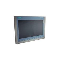
| Product Description | SIMATIC HMI, KTP1200 Basic, Basic Panel, Key/touch operation, 12" TFT display, 65536 colors, PROFINET interface, configurable from WinCC Basic V13/ STEP 7 Basic V13, contains open-source software, which is provided free of charge see enclosed CD |
| Product family | Standard devices 2nd Generation |
| Product Lifecycle (PLM) | PM300:Active Product |
| Additional Product Information | |
| EAN | 4034106029241 |
| UPC | 887621895433 |
| Commodity Code | 85371091 |
| LKZ_FDB/ CatalogID | ST80.1J |
| Product Group | 2262 |
| Group Code | R141 |
| Country of origin | China |
| SCIP number | Not available |
| Delivery information | |
| Net Weight (lb) | 4.519 lb |
| Package size unit of measure | Inch |
| Packaging Quantity | 1 |
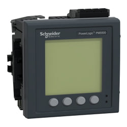
This device is a flush-mount energy meter with a 96mm by 96mm backlit LCD display. The meter provides Class 0.2S accuracy per IEC 62053-22 standard and 128 samples per cycle. The meter will measure Energy, Active and Reactive Power, Voltage, Current, Frequency, Power Factor and up to the 63rd Harmonic. Include 1.1 MegaBytes of memory for up to 14 selectable parameters with configurable interval and duration. This meter also feature the direct monitoring of neutral current. The meter will function in a 50Hz or 60Hz network and accepts supply voltage ranging from 100 to 480 VAC and 125 to 250 VDC. Line rated current for this meter is 1A or 5A input and will support Single Phase and Neutral, Three Phase, or Three Phase and Neutral configurations. The range of measurement voltage between Phases is 20 to 690 VAC at 45 to 65 Hz. Measurement range between Phase and Neutral is 20 to 400VAC at 45 to 65 Hz. Communication protocol are Modbus RTU and ASCII 2 wires with RS485 port support plus Modbus TCP/IP, Ethernet/IP and BACnet/IP based on 10/100 Mbit/s, daisy chain Ethernet with RJ45 port support. The embedded communication capabilities allow the support of the DNP 3.0 protocol, the access to an onboard web server and a Serial to Ethernet gateway. The meter also has four digital inputs with WAGES support and two digital outputs. There are 52 configurable alarms and it supports eight tariff schedules. Product dimensions are as follows: width 3.78 inches (96 millimetres), depth 3.03 inches (77 millimetres), height 3.78 inches (96 millimetres) and product weight 15.9 onces (450 g).
Main
| Characteristic | Value(s) |
|---|---|
| Range | PowerLogic |
| product name | PowerLogic PM5000 |
| Device short name | PM5560 |
| Product or Component Type | Power meter |
Complementary
| Characteristic | Value(s) |
|---|---|
| Power quality analysis | up to the 63rd harmonic |
| Metering type | Measured neutral current Calculated ground current |
| Device Application | Gateway WAGES metering Power monitoring Multi-tariff |
| Type of measurement | Current Voltage Frequency Power factor Energy Active and reactive power |
| supply voltage | 100...300 V DC 90...528 V AC 45...65 Hz |
| Network Frequency | 60 Hz 50 Hz |
| Line Rated Current | 1 A 5 A |
| type of network | 3P + N 3P 1P + N |
| Maximum power consumption in VA | 16 VA 480 V |
| Ride-through time | 35 ms 120 V AC typical 129 ms 230 V AC typical 50 ms 125 V DC typical |
| Display Type | Backlit LCD |
| Display Resolution | 128 x 128 pixels |
| Sampling rate | 128 samples/cycle |
| Measurement current | 50â¦10000 mA |
| Analogue input type | Voltage (impedance 5 MOhm) Current (impedance <= 0.3 mOhm) |
| Measurement voltage | 20â¦400 V AC 45...65 Hz between phase and neutral 20â¦828 V AC 45...65 Hz between phases |
| Frequency measurement range | 45â¦65 Hz |
| Number of inputs | 4 digital |
| Measurement accuracy | Apparent power +/- 0.5 % Frequency +/- 0.05 % Active energy +/- 0.2 % Reactive energy +/- 1 % Active power +/- 0.2 % Voltage +/- 0.1 % Power factor +/- 0.005 Current +/- 0.15 % Reactive power +/- 1 % |
| Accuracy class | Class 0.2S active energy IEC 62053-22 |
| Number of Outputs | 2 digital |
| Information displayed | Tariff 8) |
| Communication port protocol | Modbus RTU and ASCII 9.6, 19.2 and 38.4 kbauds even/odd or none - 2 wires 2500 V JBUS Modbus TCP/IP 10/100 Mbit/s 2500 V Ethernet Modbus TCP/IP daisy chain BACnet IP DNP3 over ethernet |
| Communication port support | RS485 ETHERNET |
| Communication gateway | Ethernet/serial |
| Data recording | Event logs Maintenance logs Min/max of instantaneous values Data logs Alarm logs Time stamping |
| Memory capacity | 1.1 MB |
| Web services | Alarm notification by e-mail Diagnostic via predefined web pages Web server Real time viewing of data |
| Ethernet service | SNTP client SNMP-Traps |
| Connections - terminals | Voltage circuit screw terminal block4 Control circuit screw terminal block2 Current transformer screw terminal block6 RS485 link screw terminal block4 Digital input screw terminal block8 Digital output screw terminal block4 Ethernet network RJ45 connector2 |
| Mounting Mode | Flush-mounted |
| Mounting support | Framework |
| Standards | EN 50470-3 IEC 61557-12:2015 IEC 62053-22:2020 IEC 62053-24 IEC 60529 EN 50470-1 UL 61010-1 ANSI C12.20 IEC 62053-23:2020 IEC 62052-11:2020 IEC 62052-31:2015 |
| Product certifications | CE conforming to IEC 61010-1 CULus conforming to UL 61010-1 BTL |
| Width | 3.8 in (96 mm) |
| Depth | 2.8 in (72 mm) |
| Height | 3.8 in (96 mm) |
| Product Weight | 15.9 oz (450 g) |
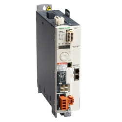
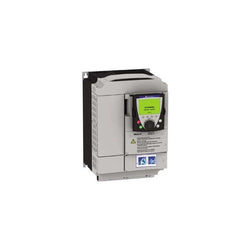
This Lexium 32 servo drive works at a rated supply voltage from 208V ac to 480V ac. It can feed 3-phase synchronous motors BMH or BSH, its continuous output current is 3A at 8kHz. The compact size of the servo drive and associated servo motor provides maximum power in the minimum space. This servo drive is specifically designed for industrial machines. It offers high performance, power and simplicity of use in motion control applications. It complies with international standards IEC/EN 61800-5-1, IEC/EN 61800-3, and is UL and CSA and is UL and CSA certified and CE marked. It has been developed to meet the requirements of directives regarding protection of the environment (RoHS).
Main
| Characteristic | Value(s) |
|---|---|
| Range of Product | Lexium 32 |
| Device short name | LXM32M |
| Product or Component Type | Motion servo drive |
| Format of the drive | Book |
| Phase | Three phase |
| [Us] rated supply voltage | 200...240 V - 15...10 % 380...480 V - 15...10 % |
| Supply voltage limits | 170â¦264 V 323â¦528 V |
| Supply frequency | 50/60 Hz - 5...5 % |
| Network Frequency | 47.5...63 Hz |
| EMC filter | Integrated |
| Continuous output current | 3 A 8 kHz |
| Output current 3s peak | 12 A 208 V 5 s 12 A 480 V 5 s |
| Continuous power | 800 W 208 V 1600 W 400 V 1600 W 480 V |
| Nominal power | 0.7 kW 208 V 8 kHz 0.9 kW 400 V 8 kHz 0.9 kW 480 V 8 kHz |
| Line current | 3.1 A 79 % 208 V, with external line choke 2 mH 3.4 A 90 % 400 V, with external line choke 2 mH 2.9 A 98 % 480 V, with external line choke 2 mH 3.6 A 136 % 208 V, without line choke 2.9 A 177 % 400 V, without line choke 2.4 A 182 % 480 V, without line choke |
Complementary
| Characteristic | Value(s) |
|---|---|
| Switching frequency | 8 kHz |
| Overvoltage category | III |
| Maximum leakage current | 30 mA |
| Output voltage | <= power supply voltage |
| Electrical isolation | Between power and control |
| Type of cable | Single-strand IEC cable 122 °F (50 °C)) copper 90 °C XLPE/EPR |
| Electrical connection | Terminal 3 mm², AWG 12 CN8) Terminal 5 mm², AWG 10 CN1) Terminal 5 mm², AWG 10 U/T1, V/T2, W/T3) |
| Tightening torque | CN8 4.4 lbf.in (0.5 N.m) CN1 6.2 lbf.in (0.7 N.m) U/T1, V/T2, W/T3 6.2 lbf.in (0.7 N.m) |
| Discrete input number | 2 capture 2 safety 4 logic |
| Discrete input type | Capture CAP Logic DI Safety compliment of STO_A, compliment of STO_B |
| Sampling duration | DI 0.25 ms discrete 0.25 ms |
| Discrete input voltage | 24 V DC capture 24 V DC logic 24 V DC safety |
| Discrete input logic | Positive compliment of STO_A, compliment of STO_B)< 5 V > 15 V EN/IEC 61131-2 type 1 Positive DI)> 19 V < 9 V EN/IEC 61131-2 type 1 Positive or negative DI)< 5 V > 15 V EN/IEC 61131-2 type 1 |
| Response time | <= 5 ms compliment of STO_A, compliment of STO_B |
| Discrete output number | 3 |
| Discrete output type | Logic DO)24 V DC |
| Discrete output voltage | <= 30 V DC |
| Discrete output logic | Positive or negative DO)EN/IEC 61131-2 |
| Contact bounce time | <= 1 ms compliment of STO_A, compliment of STO_B 2 µs CAP 0.25 µs...1.5 ms DI |
| Braking current | 50 mA |
| Response time on output | 250 µs DO)discrete |
| Control signal type | Servo motor encoder feedback Pulse train output (PTO) RS422 <500 kHz <328.08 ft (100 m) Pulse/direction (P/D), A/B, CW/CCW 5 V, 24 V link (open collector) <10 kHz <3.3 ft (1 m) Pulse/direction (P/D), A/B, CW/CCW 5 V, 24 V link (push-pull) <200 kHz <32.8 ft (10 m) Pulse/direction (P/D), A/B, CW/CCW RS422 <1000 kHz <328.08 ft (100 m) |
| Protection type | Against reverse polarity inputs signal Against short-circuits outputs signal |
| Safety function | STO (safe torque off), Integrated SS1 (safe stop 1), with separated eSM safety card SS2 (safe stop 2), with separated eSM safety card SLS (safe limited speed), with separated eSM safety card SOS (safe operating stop), with separated eSM safety card |
| Safety level | SIL 3 EN/IEC 61508 PL = e ISO 13849-1 |
| Communication interface | Modbus TCP, with separated communication card CANopen, with separated communication card CANmotion, with separated communication card Ethernet/IP, with separated communication card EtherCAT, with separated communication card Profibus, with separated communication card Profinet, with separated communication card Analog I/O, with separated communication card Digital I/O, Integrated |
| Status LED | 1 LED (Red) servo drive voltage |
| Signalling function | Display of faults 7 segments |
| Marking | CE |
| Operating position | Vertical +/- 10 degree |
| Product compatibility | Servo motor BMH 2.8 in (70 mm), 1 Servo motor BMH 2.8 in (70 mm), 2 Servo motor BMH 3.9 in (100 mm), 1 Servo motor BSH 2.8 in (70 mm), 1 Servo motor BSH 2.8 in (70 mm), 2 Servo motor BMH 2.8 in (70 mm), 3 Servo motor BSH 2.2 in (55 mm), 3 Servo motor BSH 2.8 in (70 mm), 3 Servo motor BSH 3.9 in (100 mm), 1 |
| Width | 2.7 in (68 mm) |
| Height | 10.6 in (270 mm) |
| Depth | 9.3 in (237 mm) |
| Product Weight | 4.2 lb(US) (1.9 kg) |

The GV3 manual starter and protector provides manual isolation, manual motor control, and thermal overcurrent protection in one compact unit. The basic motor starter GV3PE controls motors with full load currents up to 65 amperes. The manual starter is three pole with horsepower ratings. The manual starter is operated by a rotary handle. The Class 10 ambient compensated thermal over current is adjustable from 48 ampere to 65 ampere. This device has EVERLINK terminals. Multi standards certified (IEC, UL, CSA, CCC, EAC, Marine, ATEX).
Main
| Characteristic | Value(s) |
|---|---|
| Range | TeSys Deca |
| product name | TeSys GV3 |
| Product or Component Type | Motor circuit breaker |
| Device short name | GV3P |
| Device Application | Motor protection |
| Trip unit technology | Thermal-magnetic |
Complementary
| Characteristic | Value(s) |
|---|---|
| Poles description | 3P |
| Network type | AC |
| Utilisation category | Category A IEC 60947-2 AC-3 IEC 60947-4-1 |
| Network frequency | 50/60 Hz IEC 60947-2 |
| Motor power kW | 30 kW 400/415 V AC 50/60 Hz 45 kW 500 V AC 50/60 Hz 55 kW 690 V AC 50/60 Hz |
| Breaking capacity | 100 kA Icu 230/240 V AC 50/60 Hz IEC 60947-2 50 kA Icu 400/415 V AC 50/60 Hz IEC 60947-2 50 kA Icu 440 V AC 50/60 Hz IEC 60947-2 12 kA Icu 500 V AC 50/60 Hz IEC 60947-2 6 kA Icu 690 V AC 50/60 Hz IEC 60947-2 |
| [Ics] rated service short-circuit breaking capacity | 100 % 230/240 V AC 50/60 Hz IEC 60947-2 100 % 400/415 V AC 50/60 Hz IEC 60947-2 100 % 440 V AC 50/60 Hz IEC 60947-2 50 % 500 V AC 50/60 Hz IEC 60947-2 50 % 690 V AC 50/60 Hz IEC 60947-2 |
| Control Type | Rotary handle |
| Line Rated Current | 65 A |
| Thermal protection adjustment range | 48â¦65 A IEC 60947-2 |
| Magnetic tripping current | 910 A |
| [Ith] conventional free air thermal current | 65 A IEC 60947-2 |
| [Ue] rated operational voltage | 690 V AC 50/60 Hz IEC 60947-2 |
| [Ui] rated insulation voltage | 690 V AC 50/60 Hz IEC 60947-2 |
| [Uimp] rated impulse withstand voltage | 6 kV IEC 60947-2 |
| Phase failure sensitivity | Yes IEC 60947-4-1 |
| Suitability for isolation | Yes IEC 60947-1 |
| Power dissipation per pole | 8 W |
| Mechanical durability | 50000 cycles |
| Electrical durability | 50000 cycles AC-3 415 V In |
| Rated duty | Uninterrupted IEC 60947-4-1 |
| Tightening torque | 44.3 lbf.in (5 N.m) screw clamp terminal |
| Fixing mode | 35 mm symmetrical DIN rail clipped Panel screwed with 3 x M4 screws) |
| Mounting position | Horizontal Vertical |
| Width | 2.2 in (55 mm) |
| Height | 5.2 in (132 mm) |
| Depth | 5.4 in (136 mm) |
| Product Weight | 2.12 lb(US) (0.96 kg) |
| color | Dark grey |
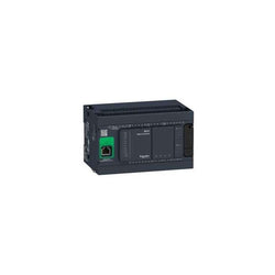
This product is part of the Modicon M241 range, an offer of logic controllers for performance demanding applications. This logic controller provides 14 discrete, 8 fast inputs, 6 relay, 4 transistor, 4 fast outputs with transistor, ethernet relay output. It has a rated supply voltage of 100V to 240V AC, an output voltage of 5V to 125V DC or 5V to 250V AC for relay, 24V DC for transistor and an output current of 2A for relay, 0.1A for fast output, 0.5A for transistor. This product enables to build application intuitively as never before due to an organised screen design. Integrated connections are USB port with mini B USB 2.0 connector, non isolated serial link 1 with RJ45 connector and RS232/RS485 interface and non isolated serial link 2 with removable screw terminal block connector and RS485 interface. It is a Modicon M241 controller with 8MB for program, 64MB for system memory RAM, 128MB built-in flash memory for backup of user programs and a SD card memory capacity of 16GB. It is an IP20 rated product. Its dimensions are 150mm (Width) x 95mm (Depth) x 90mm (Height). It weighs 0.53kg. The Modicon M241 logic controllers are designed for high-performance compact machines incorporating speed and position control functions. This product is certified by CE, IACS E10, RCM, CSA, CULus. It meets ANSI/ISA 12-12-01, CSA C22.2 No 142, CSA C22.2 No 213, EN/IEC 61131-22007, marine specification (LR, ABS, DNV, GL), UL 1604 and UL 508 standards. It supports DIN rail mount. Achieve benchmark performance while increasing profitability with the Modicon M241 through intuitive machine programming with EcoStruxure Machine Expert, ready-to-use applications and function blocks.
Main
| Characteristic | Value(s) |
|---|---|
| Range of Product | Modicon M241 |
| Product or Component Type | Logic controller |
| [Us] rated supply voltage | 100...240 V AC |
| Discrete input number | 14, discrete input 8 fast input IEC 61131-2 Type 1 |
| Discrete output type | Relay Transistor |
| Discrete output number | 6 relay 4 transistor 4 fast output |
| Discrete output voltage | 5...125 V DC relay output 5...250 V AC relay output 24 V DC transistor output |
| Discrete output current | 2 A relay output Q4...Q9) 0.1 A fast output (PTO mode) TR0...TR3) 0.5 A transistor output TR0...TR3) |
Complementary
| Characteristic | Value(s) |
|---|---|
| Discrete I/O number | 24 |
| Maximum number of I/O expansion module | 7 (local I/O-Architecture) 14 (remote I/O-Architecture) |
| Supply voltage limits | 85â¦264 V |
| Network Frequency | 50/60 Hz |
| Discrete input logic | Sink or source |
| Discrete input voltage | 24 V |
| Discrete input voltage type | DC |
| Voltage state 1 guaranteed | >= 15 V input |
| Voltage state 0 guaranteed | <= 5 V input |
| Discrete input current | 5 mA input |
| Input impedance | 4.7 kOhm input |
| Response time | 50 µs turn-on, I0...I13 input |
| Configurable filtering time | 1 µs fast input |
| Discrete output logic | Positive logic (source) |
| Output voltage limits | 125 V DC relay output 30 V DC transistor output 277 V AC relay output |
| Maximum output frequency | 1 kHz transistor output 20 kHz fast output (PWM mode) 100 kHz fast output (PLS mode) |
| Accuracy | +/- 0.1 % 0.02â¦0.1 kHz fast output +/- 1 % 0.1â¦1 kHz fast output |
| Protection type | Short-circuit protection transistor output Short-circuit and overload protection with automatic reset transistor output Reverse polarity protection transistor output Without protection relay output |
| Reset time | 10 ms automatic reset output 12 s automatic reset fast output |
| Memory capacity | 64 MB system memory RAM |
| Data backed up | 128 MB built-in flash memory backup of user programs |
| Data storage equipment | <= 16 GB SD card optional) |
| Battery type | BR2032 lithium non-rechargeable 4 year(s) |
| Backup time | 2 years 77 °F (25 °C) |
| Execution time for 1 KInstruction | 0.3 ms event and periodic task 0.7 ms other instruction |
| Application structure | 8 external event tasks 3 cyclic master tasks + 1 freewheeling task 8 event tasks 4 cyclic master tasks |
| Realtime clock | With |
| Clock drift | <= 60 s/month 77 °F (25 °C) |
| Positioning functions | PTO 4 100 kHz) |
| Counting input number | 4 fast input (HSC mode) 200 kHz 14 standard input 1 kHz |
| Control signal type | A/B 100 kHz fast input (HSC mode) Pulse/direction 200 kHz fast input (HSC mode) Single phase 200 kHz fast input (HSC mode) |
| Integrated connection type | Non isolated serial link serial 1 RJ45 RS232/RS485 Non isolated serial link serial 2 removable screw terminal block RS485 USB port mini B USB 2.0 Ethernet RJ45 |
| Supply | Serial 1)serial link supply 5 V, <200 mA |
| Transmission rate | 1.2...115.2 kbit/s (115.2 kbit/s by default) 49.2 ft (15 m) RS485 1.2...115.2 kbit/s (115.2 kbit/s by default) 9.8 ft (3 m) RS232 480 Mbit/s 9.8 ft (3 m) USB 10/100 Mbit/s Ethernet |
| Communication port protocol | Non isolated serial link Modbus master/slave |
| Port Ethernet | 10BASE-T/100BASE-TX - 1 copper cable |
| ethernet services | FDR DHCP server via TM4 Ethernet switch network module DHCP client embedded Ethernet port SMS notifications Updating firmware SNMP client/server Programming NGVL Monitoring IEC VAR ACCESS FTP client/server Downloading SQL client Modbus TCP client I/O scanner Ethernet/IP originator I/O scanner embedded Ethernet port Ethernet/IP target, Modbus TCP server and Modbus TCP slave Send and receive email from the controller based on TCP/UDP library Web server (WebVisu & XWeb system) OPC UA server DNS client |
| Local signalling | 1 LED (green) for PWR 1 LED (green) for RUN 1 LED (red) for module error (ERR) 1 LED (red) for I/O error (I/O) 1 LED (green) for SD card access (SD) 1 LED (red) for BAT 1 LED (green) for SL1 1 LED (green) for SL2 1 LED (red) for bus fault on TM4 (TM4) 1 LED per channel (green) for I/O state 1 LED (green) for Ethernet port activity |
| Electrical connection | removable screw terminal block for inputs and outputs pitch 5.08 mm) removable screw terminal block for connecting the 24 V DC power supply pitch 5.08 mm) |
| Maximum cable distance between devices | Unshielded cable <164.04 ft (50 m) input Shielded cable <32.8 ft (10 m) fast input Unshielded cable <164.04 ft (50 m) output Shielded cable <9.8 ft (3 m) fast output |
| Insulation | Between supply and internal logic 500 V AC Non-insulated between supply and ground |
| Marking | CE |
| Sensor power supply | 24 V DC 400 mA supplied by the controller |
| Surge withstand | 2 kV power lines (AC) common mode IEC 61000-4-5 2 kV relay output common mode IEC 61000-4-5 1 kV shielded cable common mode IEC 61000-4-5 1 kV power lines (AC) differential mode IEC 61000-4-5 1 kV relay output differential mode IEC 61000-4-5 1 kV input common mode IEC 61000-4-5 1 kV transistor output common mode IEC 61000-4-5 |
| Web services | Web server |
| Maximum number of connections | 8 Modbus server 8 SoMachine protocol 10 web server 4 FTP server 16 Ethernet/IP target 8 Modbus client |
| Number of server device(s) | 64 Modbus TCP 16 EtherNet/IP |
| Cycle time | 10 ms 16 EtherNet/IP 64 ms 64 Modbus TCP |
| Mounting support | Top hat type TH35-15 rail IEC 60715 Top hat type TH35-7.5 rail IEC 60715 plate or panel with fixing kit |
| Height | 3.5 in (90 mm) |
| Depth | 3.7 in (95 mm) |
| Width | 5.9 in (150 mm) |
| Product Weight | 1.17 lb(US) (0.53 kg) |
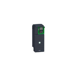
Variable Speed Drive - ATV930 - 15kW - 400/480V - with braking unit - IP21
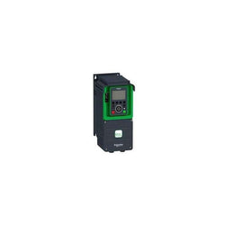
Variable Speed Drive ATV630 - 1.5kW/2hp - 380...480V - IP21/UL type 1
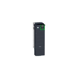
Variable Speed Drive ATV630 - 90kW/125hp - 380...480V - IP21/UL type 1
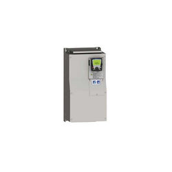
Variable Speed Drive Altivar 61 - 37kW 50hp 480V 3 Phases EMC IP20 with Graphic Terminal
Main
| Characteristic | Value(s) |
|---|---|
| Range of Product | Altivar 61 |
| Product or Component Type | Variable speed drive |
| Product Specific Application | Pumping and ventilation machine |
| Component name | ATV61 |
| Motor power kW | 18.5 kW, 3 phase 380...480 V |
| Maximum Horse Power Rating | 25 hp, 3 phase 380...480 V |
| power supply voltage | 380...480 V - 15...10 % |
| supply number of phases | 3 phase |
| Line current | 37.5 A 480 V 3 phase 18.5 kW / 25 hp 45.5 A 380 V 3 phase 18.5 kW / 25 hp |
| EMC filter | Level 3 EMC filter |
| Assembly style | With heat sink |
| Apparent power | 29.9 kVA 380 V 3 phase 18.5 kW / 25 hp |
| maximum prospective line Isc | 22 kA 3 phase |
| Maximum transient current | 49.2 A 60 s, 3 phase |
| Nominal switching frequency | 12 kHz |
| Switching frequency | 1...16 kHz adjustable 12...16 kHz with derating factor |
| asynchronous motor control | Voltage/frequency ratio, 5 points Voltage/frequency ratio, 2 points Flux vector control without sensor, standard Voltage/frequency ratio - Energy Saving, quadratic U/f |
| Synchronous motor control profile | Vector control without sensor, standard |
| Communication Port Protocol | CANopen Modbus |
| Type of polarization | No impedance Modbus |
| Option card | Communication card APOGEE FLN Communication card BACnet Communication card CC-Link Controller inside programmable card Communication card DeviceNet Communication card EtherNet/IP Communication card Fipio I/O extension card Communication card Interbus-S Communication card LonWorks Communication card METASYS N2 Communication card Modbus Plus Communication card Modbus TCP Communication card Modbus/Uni-Telway Multi-pump card Communication card Profibus DP Communication card Profibus DP V1 |
Complementary
| Characteristic | Value(s) |
|---|---|
| Product destination | Synchronous motors Asynchronous motors |
| power supply voltage limits | 323â¦528 V |
| power supply frequency | 50...60 Hz - 5...5 % |
| power supply frequency limits | 47.5...63 Hz |
| Continuous output current | 34 A 12 kHz, 460 V - 3 phase 41 A 12 kHz, 380 V - 3 phase |
| Output frequency | 0.1â¦599 Hz |
| Speed range | 1â¦100 in open-loop mode, without speed feedback |
| Speed accuracy | +/- 10 % of nominal slip 0.2 Tn to Tn without speed feedback |
| Torque accuracy | +/- 15 % in open-loop mode, without speed feedback |
| Transient overtorque | 130 % of nominal motor torque +/- 10 % 60 s |
| Braking torque | <= 125 % with braking resistor 30 % without braking resistor |
| Regulation loop | Frequency PI regulator |
| Motor slip compensation | Adjustable Can be suppressed Not available in voltage/frequency ratio (2 or 5 points) Automatic whatever the load |
| diagnostic | 1 LED (red) for drive voltage |
| Output voltage | <= power supply voltage |
| electrical isolation | Between power and control terminals |
| type of cable for mounting in an enclosure | With an IP21 or an IP31 kit 3 IEC cable 104 °F (40 °C), copper 70 °C / PVC With UL Type 1 kit 3 UL 508 cable 104 °F (40 °C), copper 75 °C / PVC Without mounting kit 1 IEC cable 113 °F (45 °C), copper 70 °C / PVC Without mounting kit 1 IEC cable 113 °F (45 °C), copper 90 °C / XLPE/EPR |
| Electrical connection | Terminal 2.5 mm² / AWG 14 AI1-/AI1+, AI2, AO1, R1A, R1B, R1C, R2A, R2B, LI1...LI6, PWR) Terminal 25 mm² / AWG 3 L1/R, L2/S, L3/T, U/T1, V/T2, W/T3, PC/-, PO, PA/+, PA, PB) |
| Tightening torque | 5.3 lbf.in (0.6 N.m) AI1-/AI1+, AI2, AO1, R1A, R1B, R1C, R2A, R2B, LI1...LI6, PWR) 47.8 lbf.in (5.4 N.m), 47.7 lb.in L1/R, L2/S, L3/T, U/T1, V/T2, W/T3, PC/-, PO, PA/+, PA, PB) |
| Supply | Internal supply for reference potentiometer (1 to 10 kOhm) 10.5 V DC, +/- 5 %, <10 mA overload and short-circuit protection Internal supply 24 V DC 21â¦27 V), <200 mA overload and short-circuit protection External supply 24 V DC 19â¦30 V) |
| Analogue input number | 2 |
| Analogue input type | AI1-/Al1+ bipolar differential voltage +/- 10 V DC 24 V max 11 bits + sign AI2 software-configurable current 0...20 mA 242 Ohm 11 bits AI2 software-configurable voltage 0...10 V DC 24 V max 30000 Ohm 11 bits |
| sampling time | 2 ms +/- 0.5 ms AI1-/Al1+) - analog input 2 ms +/- 0.5 ms Al2) - analog input 2 ms +/- 0.5 ms AO1) - analog output 2 ms +/- 0.5 ms LI1...LI5) - discrete input 2 ms +/- 0.5 ms LI6)if configured as logic input - discrete input |
| absolute accuracy precision | +/- 0.6 % AI1-/Al1+) for a temperature variation 60 °C +/- 0.6 % AI2) for a temperature variation 60 °C +/- 1 % AO1) for a temperature variation 60 °C |
| Linearity error | +/- 0.15 % of maximum value AI1-/Al1+) +/- 0.15 % of maximum value AI2) +/- 0.2 % AO1) |
| Analogue output number | 1 |
| Analogue output type | AO1 software-configurable current 0...20 mA 500 Ohm 10 bits AO1 software-configurable voltage 0...10 V DC 470 Ohm 10 bits AO1 software-configurable logic output 10 V, 20 mA |
| Discrete output number | 2 |
| Discrete output type | Configurable relay logic R1A, R1B, R1C) NO/NC - 100000 cycles Configurable relay logic R2A, R2B) NO - 100000 cycles |
| maximum response time | <= 100 ms in STO (Safe Torque Off) R1A, R1B, R1C <= 7 ms +/- 0.5 ms R2A, R2B <= 7 ms +/- 0.5 ms |
| Minimum switching current | 3 mA 24 V DC configurable relay logic |
| Maximum switching current | R1, R2 2 A 250 V AC inductive, cos phi = 0.4 7 ms R1, R2 2 A 30 V DC inductive, cos phi = 0.4 7 ms R1, R2 5 A 250 V AC resistive, cos phi = 1 0 ms R1, R2 5 A 30 V DC resistive, cos phi = 1 0 ms |
| Discrete input number | 7 |
| Discrete input type | Programmable LI1...LI5) 24 V DC <= 30 V)level 1 PLC - 3500 Ohm Switch-configurable LI6) 24 V DC <= 30 V)level 1 PLC - 3500 Ohm Switch-configurable PTC probe LI6)0â¦6 - 1500 Ohm Safety input PWR) 24 V DC <= 30 V) - 1500 Ohm |
| Discrete input logic | Negative logic (sink) LI1...LI5), > 16 V, < 10 V Positive logic (source) LI1...LI5), < 5 V, > 11 V Negative logic (sink) LI6)if configured as logic input, > 16 V, < 10 V Positive logic (source) LI6)if configured as logic input, < 5 V, > 11 V |
| Acceleration and deceleration ramps | Automatic adaptation of ramp if braking capacity exceeded, by using resistor S, U or customized Linear adjustable separately from 0.01 to 9000 s |
| Braking to standstill | By DC injection |
| Protection type | Against exceeding limit speed drive Against input phase loss drive Break on the control circuit drive Input phase breaks drive Line supply overvoltage drive Line supply undervoltage drive Overcurrent between output phases and earth drive Overheating protection drive Overvoltages on the DC bus drive Power removal drive Short-circuit between motor phases drive Thermal protection drive Motor phase break motor Power removal motor Thermal protection motor |
| Insulation resistance | > 1 mOhm 500 V DC for 1 minute to earth |
| Frequency resolution | Analog input 0.024/50 Hz Display unit 0.1 Hz |
| Connector type | 1 RJ45 on front face)Modbus 1 RJ45 on terminal)Modbus Male SUB-D 9 on RJ45CANopen |
| Physical interface | 2-wire RS 485 Modbus |
| Transmission frame | RTU Modbus |
| Transmission rate | 4800 bps, 9600 bps, 19200 bps, 38.4 Kbps Modbus on terminal 9600 bps, 19200 bps Modbus on front face 20 kbps, 50 kbps, 125 kbps, 250 kbps, 500 kbps, 1 Mbps CANopen |
| Data format | 8 bits, 1 stop, even parity Modbus on front face 8 bits, odd even or no configurable parity Modbus on terminal |
| Number of addresses | 1â¦127 CANopen 1â¦247 Modbus |
| Method of access | Slave CANopen |
| Marking | CE |
| Operating position | Vertical +/- 10 degree |
| Product Weight | 48.5 lb(US) (22 kg) |
| Width | 9.06 in (230 mm) |
| Height | 15.7 in (400 mm) |
| Depth | 8.4 in (213 mm) |
This rear panel is compatible with Harmony STU human machine interfaces (HMIs). It is made of PC/PBT and available in dark gray. Its dimensions are 118mm (width) x 40.1mm (depth). It is suitable for simple machines and infrastructure applications. This panel is compatible with HMISTU655, HMISTU655W, HMISTU855 and HMISTU855W. Harmony STO (fromerly known as Magelis STO) is powered by the EcoStruxure operator terminal expert and STU (fromerly known as Magelis STU) is powered by Vijeo Designer.
Main
| Characteristic | Value(s) |
|---|---|
| Range of Product | Harmony STU |
| Product or Component Type | Rear panel |
Complementary
| Characteristic | Value(s) |
|---|---|
| Enclosure Material | PC/PBT |
| Height | 3.86 in (98.15 mm) |
| Width | 4.6 in (118 mm) |
| Depth | 1.6 in (40.1 mm) |
| Product Weight | 0.780 lb(US) (0.354 kg) |
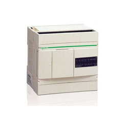
Main
| Characteristic | Value(s) |
|---|---|
| Range of Product | Twido |
| Product or Component Type | Compact base controller |
| Discrete I/O number | 24 |
| Discrete input number | 14 |
| Discrete input voltage | 24 V |
| Discrete input voltage type | DC |
| Discrete output number | 10 relay |
| [Us] rated supply voltage | 100...240 V AC |
| Maximum Number of I/O Expansion Module | 4 |
| Use of slot | Memory cartridge or realtime clock cartridge |
| Data backed up | Internal RAM lithium, 30 days 10 h 10 year(s) |
| Integrated connection type | Power supply Non isolated serial link mini DIN, Modbus/character mode master/slave RTU/ASCII RS485) half duplex, 38.4 kbit/s Serial link interface adaptor RS232C/RS485) |
| Complementary function | Event processing PID |
| Range Compatibility | Twido |
Complementary
| Characteristic | Value(s) |
|---|---|
| Discrete input logic | Sink or source |
| Input voltage limits | 20.4...28.8 V |
| Discrete input current | 11 mA I0.0 to I0.1 7 mA I0.2 to I0.13 |
| Input impedance | 2100 Ohm I0.0 to I0.1 3400 Ohm I0.2 to I0.13 |
| Filter time | 150 µs + programmed filter time for I0.6 to I0.13 at state 0 35 µs + programmed filter time for I0.0 to I0.5 at state 1 40 µs + programmed filter time for I0.6 to I0.13 at state 1 45 µs + programmed filter time for I0.0 to I0.5 at state 0 |
| Insulation between channel and internal logic | 1500 Vrms for 1 minute |
| Insulation resistance between channel | None |
| Minimum load | 0.1 mA |
| Contact resistance | 30000 µOhm |
| Load current | 2 A 240 V AC inductive 30 cyc/mn relay output 2 A 240 V AC resistive 30 cyc/mn relay output 2 A 30 V DC inductive 30 cyc/mn relay output 2 A 30 V DC resistive 30 cyc/mn relay output |
| Mechanical durability | 20000000 cycles relay output |
| Electrical durability | 100000 cycles relay output |
| Current consumption | 36 mA 5 V DC at state 1 5 mA 5 V DC at state 0 55 mA 24 V DC at state 1 |
| I/O connection | Non-removable screw terminal block |
| Maximum input/output number | 120 spring terminal block with I/O expansion module 152 HE-10 connector with I/O expansion module 88 removable screw terminal block with I/O expansion module |
| Network Frequency | 50/60 Hz |
| Supply voltage limits | 85â¦264 V |
| Network frequency limits | 47â¦63 Hz |
| Power supply output current | 0.25 A 24 V DC sensors |
| Input current | 450 mA |
| Inrush current | 40 A |
| Protection type | Power protection internal fuse |
| Power consumption in VA | 33 VA 100 V 40 VA 264 V |
| Insulation resistance | > 10 MOhm at 500 V, between I/O and earth terminals > 10 MOhm at 500 V, between supply and earth terminals |
| Program memory | 3000 instructions |
| Exact time for 1 Kinstruction | 1 ms |
| System overhead | 0.5 ms |
| Memory description | Internal RAM, 128 counters, no floating, no trigonometrical Internal RAM, 128 timers, no floating, no trigonometrical Internal RAM, 256 internal bits, no floating, no trigonometrical Internal RAM, 3000 internal words, no floating, no trigonometrical Internal RAM, double words, no floating, no trigonometrical |
| Free slots | 1 |
| Realtime clock | Without |
| Counting input number | 1 20000 Hz 32 bits 3 5000 Hz 16 bits |
| Analogue adjustment points | 1 point adjustable from 0 to 511 points 1 point adjustable from 0...1023 |
| Status LED | 1 LED (Green) PWR 1 LED (Green) RUN 1 LED per channel (Green) I/O status 1 LED (Red) module error (ERR) 1 LED user pilot light (STAT) |
| Depth | 2.8 in (70 mm) |
| Height | 3.7 in (95 mm) |
| Width | 3.5 in (90 mm) |
| Terminals description PLC n°1 | (6)IN_DIS#6 COM_NEG#0-13 (-)PW_OUT_NEG (4)IN_DIS#4 ALT (0)IN_DIS#0 (13)IN_DIS#13 (5)IN_DIS#5 (8)IN_DIS#8 (10)IN_DIS#10 (11)IN_DIS#11 TB_TOP (+)PW_OUT_POS (9)IN_DIS#9 (3)IN_DIS#3 (7)IN_DIS#7 (12)IN_DIS#12 (1)IN_DIS#1 (2)IN_DIS#2 |
| Terminals description PLC n°2 | (11)IN_DIS#10 (9)IN_DIS#9 (2)IN_DIS#2 (1)IN_DIS#1 (7)IN_DIS#7 (3)IN_DIS#3 (8)IN_DIS#8 (+)PW_OUT_POS ALT_1 COM_POS#0-13 (12)IN_DIS#12 (-)PW_OUT_NEG (4)IN_DIS#4 (13)IN_DIS#13 TB_TOP (6)IN_DIS#6 (10)IN_DIS#10 (0)IN_DIS#0 (5)IN_DIS#5 |
| Terminals description PLC n°3 | (COM0)COM#0-3 (9)OUT_DIS#9 (7)OUT_DIS#7 (3)OUT_DIS#3 (1)OUT_DIS#1 (GND)GROUND (6)OUT_DIS#6 (-)PW_NEG (COM2)COM#8 TB_BOTTOM (COM1)COM#4-7 (8)OUT_DIS#8 (COM3)COM#9 (5)OUT_DIS#5 (4)OUT_DIS#4 (2)OUT_DIS#2 (0)OUT_DIS#0 (+)PW_POS |
| Product Weight | 0.672 lb(US) (0.305 kg) |
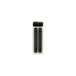
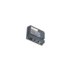
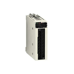
This product is part of the Modicon X80 range, a common platform of modules for Modicon M580 and M340 Programmable Automation Controllers (PAC). This discrete input module has 64 inputs with sink (positive) logic. It is an input module with an input voltage of 24V DC, a current consumption of 200mA at 3.3V DC and a power dissipation of 4.3W. There is an isolation between channels. This product is robust, high quality and based on the latest innovative technology. It has an external fuse per group of channel 0.5A fast blow and without reverse polarity protection type. It offers 362681 hours of MTBF. It is an IP20 rated product. It weighs 0.145kg. It is suitable for medium to large process applications. This product is certified by EAC, RCM, UL, CSA, Merchant Navy, CE. It meets IEC 61131-2, CSA C22.2 No 142, CSA C22.2 No 213 and UL 508 standards. Modicon X80 consists in a compatible modules common platform that reduce maintenance and training costs with same spare parts in stock, and unique training for different Programmable Automation Controllers (PAC).
Main
| Characteristic | Value(s) |
|---|---|
| Range of Product | Modicon X80 |
| Product or Component Type | Discrete input module |
| Discrete input number | 64 |
| Discrete input type | Isolated |
| Input type | Current sink (logic positive) |
| Discrete input voltage | 24 V DC positive |
| Discrete input current | 0.6 mA |
Complementary
| Characteristic | Value(s) |
|---|---|
| Sensor power supply | 19...30 V |
| Input impedance | 40000 Ohm |
| Insulation resistance | > 10 MOhm 500 V DC |
| Power dissipation in W | 4.3 W |
| DC typical response time | 4 ms |
| DC maximum response time | 7 ms |
| Paralleling of inputs | No |
| Typical current consumption | 160 mA 3.3 V DC |
| MTBF reliability | 510000 H |
| Protection type | 1 external fuse per group of channel 0.5 A fast blow without reverse polarity protection |
| Voltage detection threshold | < 14 V DC sensor fault > 18 V DC sensor OK |
| Status LED | 1 LED (Green) +32 channels indicator 1 LED (Green) module operating (RUN) 1 LED per channel (Green) channel diagnostic 1 LED (Red) module error (ERR) 1 LED (Red) module I/O |
| Product Weight | 0.320 lb(US) (0.145 kg) |
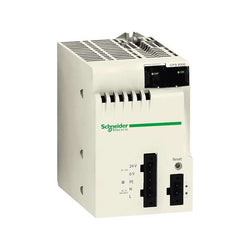
Power supply module X80 - 100..240 V AC - 20 W
Analog input module X80 - 4 inputs - high speed
Main
| Characteristic | Value(s) |
|---|---|
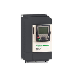
| Range of Product | Altivar 71 |
| Product or Component Type | Variable speed drive |
| Product Specific Application | Complex, high-power machines |
| Component name | ATV71 |
| Motor power kW | 7.5 kW, 3 phase 380...480 V |
| Maximum Horse Power Rating | 10 hp, 3 phase 380...480 V |
| Maximum motor cable length | 164.04 ft (50 m) shielded cable 328.08 ft (100 m) unshielded cable |
| power supply voltage | 380...480 V - 15...10 % |
| Phase | 3 phase |
| Line current | 22.2 A 480 V 3 phase 7.5 kW / 10 hp 27 A 380 V 3 phase 7.5 kW / 10 hp |
| EMC filter | Integrated |
| Assembly style | With heat sink |
| Variant | Without remote graphic terminal |
| Apparent power | 17.8 kVA 380 V 3 phase 7.5 kW / 10 hp |
| Prospective line Isc | 22 kA 3 phase |
| Nominal output current | 14 A 4 kHz 460 V 3 phase 7.5 kW / 10 hp 17.6 A 4 kHz 380 V 3 phase 7.5 kW / 10 hp |
| Maximum transient current | 26.4 A 60 s 3 phase 7.5 kW / 10 hp 29 A 2 s 3 phase 7.5 kW / 10 hp |
| Output frequency | 0.1â¦599 Hz |
| Nominal switching frequency | 4 kHz |
| Switching frequency | 1...16 kHz adjustable 4...16 kHz with derating factor |
| Asynchronous motor control profile | Voltage/frequency ratio (2 or 5 points) ENA (Energy adaptation) system for unbalanced loads Flux vector control (FVC) with sensor (current vector) Sensorless flux vector control (SFVC) (voltage or current vector) |
| Type of polarization | No impedance Modbus |
Complementary
| Characteristic | Value(s) |
|---|---|
| Product destination | Synchronous motors Asynchronous motors |
| power supply voltage limits | 323â¦528 V |
| power supply frequency | 50...60 Hz - 5...5 % |
| power supply frequency limits | 47.5...63 Hz |
| Speed range | 1â¦100 asynchronous motor in open-loop mode, without speed feedback 1â¦1000 asynchronous motor in closed-loop mode with encoder feedback 1â¦50 synchronous motor in open-loop mode, without speed feedback |
| Speed accuracy | +/- 0.01 % of nominal speed in closed-loop mode with encoder feedback 0.2 Tn to Tn +/- 10 % of nominal slip without speed feedback 0.2 Tn to Tn |
| Torque accuracy | +/- 15 % in open-loop mode, without speed feedback +/- 5 % in closed-loop mode with encoder feedback |
| Transient overtorque | 170 % +/- 10 % 60 s every 10 minutes 220 % +/- 10 % 2 s |
| Braking torque | <= 150 % with braking or hoist resistor 30 % without braking resistor |
| Synchronous motor control profile | Vector control without speed feedback |
| Regulation loop | Adjustable PI regulator |
| Motor slip compensation | Suppressable Adjustable Not available in voltage/frequency ratio (2 or 5 points) Automatic whatever the load |
| diagnostic | 1 LED (red) for drive voltage |
| Output voltage | <= power supply voltage |
| Insulation | Electrical between power and control |
| type of cable for mounting in an enclosure | With a NEMA Type1 kit 3 UL 508 cable 104 °F (40 °C), copper 75 °C / PVC With an IP21 or an IP31 kit 3 IEC cable 104 °F (40 °C), copper 70 °C / PVC Without mounting kit 1 IEC cable 113 °F (45 °C), copper 70 °C / PVC Without mounting kit 1 IEC cable 113 °F (45 °C), copper 90 °C / XLPE/EPR |
| Electrical connection | Terminal 2.5 mm², AWG 14 AI1-/AI1+, AI2, AO1, R1A, R1B, R1C, R2A, R2B, LI1...LI6, PWR) Terminal 6 mm², AWG 8 L1/R, L2/S, L3/T, U/T1, V/T2, W/T3, PC/-, PO, PA/+, PA, PB) |
| Tightening torque | 5.3 lbf.in (0.6 N.m) AI1-/AI1+, AI2, AO1, R1A, R1B, R1C, R2A, R2B, LI1...LI6, PWR) 26.6 lbf.in (3 N.m), 26.5 lb.in L1/R, L2/S, L3/T, U/T1, V/T2, W/T3, PC/-, PO, PA/+, PA, PB) |
| Supply | Internal supply for reference potentiometer (1 to 10 kOhm) 10.5 V DC +/- 5 %, <10 mA overload and short-circuit protection Internal supply 24 V DC 21â¦27 V), <200 mA overload and short-circuit protection |
| Analogue input number | 2 |
| Analogue input type | AI1-/Al1+ bipolar differential voltage +/- 10 V DC 24 V max 11 bits + sign AI2 software-configurable current 0...20 mA 242 Ohm 11 bits AI2 software-configurable voltage 0...10 V DC 24 V max 30000 Ohm 11 bits |
| input sampling time | 2 ms +/- 0.5 ms AI1-/Al1+) - analog 2 ms +/- 0.5 ms Al2) - analog 2 ms +/- 0.5 ms LI1...LI5) - discrete 2 ms +/- 0.5 ms LI6)if configured as logic input - discrete |
| Response time | <= 100 ms in STO (Safe Torque Off) AO1 2 ms +/- 0.5 ms analog R1A, R1B, R1C 7 ms +/- 0.5 ms discrete R2A, R2B 7 ms +/- 0.5 ms discrete |
| absolute accuracy precision | +/- 0.6 % AI1-/Al1+) for a temperature variation 60 °C +/- 0.6 % AI2) for a temperature variation 60 °C +/- 1 % AO1) for a temperature variation 60 °C |
| Linearity error | +/- 0.15 % of maximum value AI1-/Al1+, AI2) +/- 0.2 % AO1) |
| Analogue output number | 1 |
| Analogue output type | AO1 software-configurable logic output 10 V 20 mA AO1 software-configurable current 0...20 mA 500 Ohm 10 bits AO1 software-configurable voltage 0...10 V DC 470 Ohm 10 bits |
| Discrete output number | 2 |
| Discrete output type | Configurable relay logic R1A, R1B, R1C) NO/NC - 100000 cycles Configurable relay logic R2A, R2B) NO - 100000 cycles |
| Minimum switching current | 3 mA 24 V DC configurable relay logic |
| Maximum switching current | R1, R2 2 A 250 V AC inductive, cos phi = 0.4 R1, R2 2 A 30 V DC inductive, cos phi = 0.4 R1, R2 5 A 250 V AC resistive, cos phi = 1 R1, R2 5 A 30 V DC resistive, cos phi = 1 |
| Discrete input number | 7 |
| Discrete input type | LI1...LI5 programmable 24 V DC level 1 PLC 3500 Ohm LI6 switch-configurable 24 V DC level 1 PLC 3500 Ohm LI6 switch-configurable PTC probe 0â¦6 1500 Ohm PWR safety input 24 V DC 1500 Ohm ISO 13849-1 level d |
| Discrete input logic | Negative logic (sink) LI1...LI5), > 16 V, < 10 V Positive logic (source) LI1...LI5), < 5 V, > 11 V Negative logic (sink) LI6)if configured as logic input, > 16 V, < 10 V Positive logic (source) LI6)if configured as logic input, < 5 V, > 11 V |
| Acceleration and deceleration ramps | Linear adjustable separately from 0.01 to 9000 s S, U or customized Automatic adaptation of ramp if braking capacity exceeded, by using resistor |
| Braking to standstill | By DC injection |
| Protection type | Against exceeding limit speed drive Against input phase loss drive Break on the control circuit drive Input phase breaks drive Line supply overvoltage drive Line supply undervoltage drive Overcurrent between output phases and earth drive Overheating protection drive Overvoltages on the DC bus drive Short-circuit between motor phases drive Thermal protection drive Motor phase break motor Power removal motor Thermal protection motor |
| Insulation resistance | > 1 mOhm 500 V DC for 1 minute to earth |
| Frequency resolution | Analog input 0.024/50 Hz Display unit 0.1 Hz |
| Communication Port Protocol | Modbus CANopen |
| Connector type | 1 RJ45 on front face)Modbus 1 RJ45 on terminal)Modbus Male SUB-D 9 on RJ45CANopen |
| Physical interface | 2-wire RS 485 Modbus |
| Transmission frame | RTU Modbus |
| Transmission rate | 4800 bps, 9600 bps, 19200 bps, 38.4 Kbps Modbus on terminal 9600 bps, 19200 bps Modbus on front face 20 kbps, 50 kbps, 125 kbps, 250 kbps, 500 kbps, 1 Mbps CANopen |
| Data format | 8 bits, 1 stop, even parity Modbus on front face 8 bits, odd even or no configurable parity Modbus on terminal |
| Number of addresses | 1â¦127 CANopen 1â¦247 Modbus |
| Method of access | Slave CANopen |
| Marking | CE |
| Operating position | Vertical +/- 10 degree |
| Height | 11.6 in (295 mm) |
| Depth | 7.4 in (187 mm) |
| Width | 6.9 in (175 mm) |
| Product Weight | 12.1 lb(US) (5.5 kg) |
| Option card | Communication card CC-Link Controller inside programmable card Communication card DeviceNet Communication card EtherNet/IP Communication card Fipio I/O extension card Communication card Interbus-S Interface card for encoder Communication card Modbus Plus Communication card Modbus TCP Communication card Modbus/Uni-Telway Overhead crane card Communication card Profibus DP Communication card Profibus DP V1 |
Main
| Characteristic | Value(s) |
|---|---|
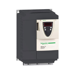
| Range of Product | Altivar 71 |
| Product or Component Type | Variable speed drive |
| Product Specific Application | Complex, high-power machines |
| Component name | ATV71 |
| Motor power kW | 18.5 kW, 3 phase 380...480 V |
| Maximum Horse Power Rating | 25 hp, 3 phase 380...480 V |
| Maximum motor cable length | 164.04 ft (50 m) shielded cable 328.08 ft (100 m) unshielded cable |
| power supply voltage | 380...480 V - 15...10 % |
| Phase | 3 phase |
| Line current | 37.5 A 480 V 3 phase 18.5 kW / 25 hp 45.5 A 380 V 3 phase 18.5 kW / 25 hp |
| EMC filter | Integrated |
| Assembly style | With heat sink |
| Variant | Without remote graphic terminal |
| Apparent power | 29.9 kVA 380 V 3 phase 18.5 kW / 25 hp |
| Prospective line Isc | 22 kA 3 phase |
| Nominal output current | 34 A 4 kHz 460 V 3 phase 18.5 kW / 25 hp 41 A 4 kHz 380 V 3 phase 18.5 kW / 25 hp |
| Maximum transient current | 61.5 A 60 s 3 phase 18.5 kW / 25 hp 67.7 A 2 s 3 phase 18.5 kW / 25 hp |
| Output frequency | 0.1â¦599 Hz |
| Nominal switching frequency | 4 kHz |
| Switching frequency | 1...16 kHz adjustable 4...16 kHz with derating factor |
| Asynchronous motor control profile | ENA (Energy adaptation) system for unbalanced loads Flux vector control (FVC) with sensor (current vector) Voltage/frequency ratio (2 or 5 points) Sensorless flux vector control (SFVC) (voltage or current vector) |
| Type of polarization | No impedance Modbus |
Complementary
| Characteristic | Value(s) |
|---|---|
| Product destination | Asynchronous motors Synchronous motors |
| power supply voltage limits | 323â¦528 V |
| power supply frequency | 50...60 Hz - 5...5 % |
| power supply frequency limits | 47.5...63 Hz |
| Speed range | 1â¦100 asynchronous motor in open-loop mode, without speed feedback 1â¦1000 asynchronous motor in closed-loop mode with encoder feedback 1â¦50 synchronous motor in open-loop mode, without speed feedback |
| Speed accuracy | +/- 0.01 % of nominal speed in closed-loop mode with encoder feedback 0.2 Tn to Tn +/- 10 % of nominal slip without speed feedback 0.2 Tn to Tn |
| Torque accuracy | +/- 15 % in open-loop mode, without speed feedback +/- 5 % in closed-loop mode with encoder feedback |
| Transient overtorque | 170 % +/- 10 % 60 s every 10 minutes 220 % +/- 10 % 2 s |
| Braking torque | <= 150 % with braking or hoist resistor 30 % without braking resistor |
| Synchronous motor control profile | Vector control without speed feedback |
| Regulation loop | Adjustable PI regulator |
| Motor slip compensation | Not available in voltage/frequency ratio (2 or 5 points) Automatic whatever the load Suppressable Adjustable |
| diagnostic | 1 LED (red) for drive voltage |
| Output voltage | <= power supply voltage |
| Insulation | Electrical between power and control |
| type of cable for mounting in an enclosure | With a NEMA Type1 kit 3 UL 508 cable 104 °F (40 °C), copper 75 °C / PVC With an IP21 or an IP31 kit 3 IEC cable 104 °F (40 °C), copper 70 °C / PVC Without mounting kit 1 IEC cable 113 °F (45 °C), copper 70 °C / PVC Without mounting kit 1 IEC cable 113 °F (45 °C), copper 90 °C / XLPE/EPR |
| Electrical connection | Terminal 2.5 mm², AWG 14 AI1-/AI1+, AI2, AO1, R1A, R1B, R1C, R2A, R2B, LI1...LI6, PWR) Terminal 35 mm², AWG 2 L1/R, L2/S, L3/T, U/T1, V/T2, W/T3, PC/-, PO, PA/+, PA, PB) |
| Tightening torque | 5.3 lbf.in (0.6 N.m) AI1-/AI1+, AI2, AO1, R1A, R1B, R1C, R2A, R2B, LI1...LI6, PWR) 47.8 lbf.in (5.4 N.m), 47.7 lb.in L1/R, L2/S, L3/T, U/T1, V/T2, W/T3, PC/-, PO, PA/+, PA, PB) |
| Supply | Internal supply for reference potentiometer (1 to 10 kOhm) 10.5 V DC +/- 5 %, <10 mA overload and short-circuit protection Internal supply 24 V DC 21â¦27 V), <200 mA overload and short-circuit protection |
| Analogue input number | 2 |
| Analogue input type | AI1-/Al1+ bipolar differential voltage +/- 10 V DC 24 V max 11 bits + sign AI2 software-configurable current 0...20 mA 242 Ohm 11 bits AI2 software-configurable voltage 0...10 V DC 24 V max 30000 Ohm 11 bits |
| input sampling time | 2 ms +/- 0.5 ms AI1-/Al1+) - analog 2 ms +/- 0.5 ms Al2) - analog 2 ms +/- 0.5 ms LI1...LI5) - discrete 2 ms +/- 0.5 ms LI6)if configured as logic input - discrete |
| Response time | <= 100 ms in STO (Safe Torque Off) AO1 2 ms +/- 0.5 ms analog R1A, R1B, R1C 7 ms +/- 0.5 ms discrete R2A, R2B 7 ms +/- 0.5 ms discrete |
| absolute accuracy precision | +/- 0.6 % AI1-/Al1+) for a temperature variation 60 °C +/- 0.6 % AI2) for a temperature variation 60 °C +/- 1 % AO1) for a temperature variation 60 °C |
| Linearity error | +/- 0.15 % of maximum value AI1-/Al1+, AI2) +/- 0.2 % AO1) |
| Analogue output number | 1 |
| Analogue output type | AO1 software-configurable logic output 10 V 20 mA AO1 software-configurable current 0...20 mA 500 Ohm 10 bits AO1 software-configurable voltage 0...10 V DC 470 Ohm 10 bits |
| Discrete output number | 2 |
| Discrete output type | Configurable relay logic R1A, R1B, R1C) NO/NC - 100000 cycles Configurable relay logic R2A, R2B) NO - 100000 cycles |
| Minimum switching current | 3 mA 24 V DC configurable relay logic |
| Maximum switching current | R1, R2 2 A 250 V AC inductive, cos phi = 0.4 R1, R2 2 A 30 V DC inductive, cos phi = 0.4 R1, R2 5 A 250 V AC resistive, cos phi = 1 R1, R2 5 A 30 V DC resistive, cos phi = 1 |
| Discrete input number | 7 |
| Discrete input type | LI1...LI5 programmable 24 V DC level 1 PLC 3500 Ohm LI6 switch-configurable 24 V DC level 1 PLC 3500 Ohm LI6 switch-configurable PTC probe 0â¦6 1500 Ohm PWR safety input 24 V DC 1500 Ohm ISO 13849-1 level d |
| Discrete input logic | Negative logic (sink) LI1...LI5), > 16 V, < 10 V Positive logic (source) LI1...LI5), < 5 V, > 11 V Negative logic (sink) LI6)if configured as logic input, > 16 V, < 10 V Positive logic (source) LI6)if configured as logic input, < 5 V, > 11 V |
| Acceleration and deceleration ramps | Linear adjustable separately from 0.01 to 9000 s Automatic adaptation of ramp if braking capacity exceeded, by using resistor S, U or customized |
| Braking to standstill | By DC injection |
| Protection type | Against exceeding limit speed drive Against input phase loss drive Break on the control circuit drive Input phase breaks drive Line supply overvoltage drive Line supply undervoltage drive Overcurrent between output phases and earth drive Overheating protection drive Overvoltages on the DC bus drive Short-circuit between motor phases drive Thermal protection drive Motor phase break motor Power removal motor Thermal protection motor |
| Insulation resistance | > 1 mOhm 500 V DC for 1 minute to earth |
| Frequency resolution | Analog input 0.024/50 Hz Display unit 0.1 Hz |
| Communication Port Protocol | CANopen Modbus |
| Connector type | 1 RJ45 on front face)Modbus 1 RJ45 on terminal)Modbus Male SUB-D 9 on RJ45CANopen |
| Physical interface | 2-wire RS 485 Modbus |
| Transmission frame | RTU Modbus |
| Transmission rate | 4800 bps, 9600 bps, 19200 bps, 38.4 Kbps Modbus on terminal 9600 bps, 19200 bps Modbus on front face 20 kbps, 50 kbps, 125 kbps, 250 kbps, 500 kbps, 1 Mbps CANopen |
| Data format | 8 bits, 1 stop, even parity Modbus on front face 8 bits, odd even or no configurable parity Modbus on terminal |
| Number of addresses | 1â¦127 CANopen 1â¦247 Modbus |
| Method of access | Slave CANopen |
| Marking | CE |
| Operating position | Vertical +/- 10 degree |
| Height | 15.7 in (400 mm) |
| Depth | 8.4 in (213 mm) |
| Width | 9.06 in (230 mm) |
| Product Weight | 33.07 lb(US) (15 kg) |
| Option card | Communication card CC-Link Controller inside programmable card Communication card DeviceNet Communication card EtherNet/IP Communication card Fipio I/O extension card Communication card Interbus-S Interface card for encoder Communication card Modbus Plus Communication card Modbus TCP Communication card Modbus/Uni-Telway Overhead crane card Communication card Profibus DP Communication card Profibus DP V1 |
Variable Speed Drive Altivar ATV320 - 5.5kW - 200V - 3Phase - compact
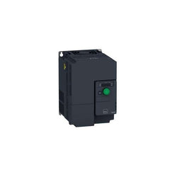
This Altivar 320 variable speed drive can feed 3-phase synchronous and asynchronous motors. Its book form factor allows for a simple and compact installation in your automation cabinets. It works at a rated power up to 11kW / 15hp and a rated voltage from 380V to 500V AC. Its robust design with IEC 60721-3-3 class 3C3 coated printed circuit boards allows to extend machine availability in harsh environmental conditions, for example at ambient temperatures of up to 60°C without the need of additional cooling. It incorporates functions suitable for the most common applications, including torque and speed accuracy at very low speed, high dynamic performance with flux vector control without sensor and extended frequency range for high-speed motors. It also incorporates parallel connection of motors and special drives using the voltage/frequency ratio and static speed accuracy and energy saving for open-loop synchronous motors. The drive software includes 5 safety functions that help machines meet safety requirements, whether or not they are used in conjunction with a Preventa safety module. These safety functions are configured using SoMove software. Altivar Machine ATV320 was designed for Original Equipment Manufacturers (OEMs) that meets simple and advanced application requirements covered for packaging, material handling, textile, material working, mechanical actuators and hoisting. It conforms to international standards IEC/EN 61800-5-1 and IEC/EN 61800-3 (immunity and conducted and radiated EMC emissions). It is also CE, UL, CSA, NOM, EAC and RCM certified. Mounting accessories and external options (braking resistors, line chokes, motor chokes, additional EMC filters) are available with Altivar Machine ATV320 drives. The type of external accessories and options depends on the drive rating. It is designed to be mounted in vertical position (+/- 10 °) on a panel, thanks to 4 fixing holes. It is fully integrated inside Schneider Electricâs EcoStruxure Machine through DTM. It is possible to configure, control, and diagnose ATV320 drives directly in SoMachine and SoMove software by means of the same software brick (DTM).
Main
| Characteristic | Value(s) |
|---|---|
| Range of Product | Altivar Machine ATV320 |
| Product or Component Type | Variable speed drive |
| Product Specific Application | Complex machines |
| Variant | Standard version |
| Format of the drive | Book |
| Mounting Mode | Wall mount |
| Communication Port Protocol | Modbus serial CANopen |
| Option card | communication module, CANopen communication module, EtherCAT communication module, Profibus DP V1 communication module, PROFINET communication module, Ethernet Powerlink communication module, EtherNet/IP communication module, DeviceNet |
| [Us] rated supply voltage | 380...500 V - 15...10 % |
| nominal output current | 27.7 A |
| Motor power kW | 11 kW heavy duty |
| EMC filter | Class C3 EMC filter integrated |
| IP degree of protection | IP20 |
Complementary
| Characteristic | Value(s) |
|---|---|
| Discrete input number | 7 |
| Discrete input type | STO safe torque off, 24 V DC1.5 kOhm DI1...DI6 logic inputs, 24 V DC 30 V) DI5 programmable as pulse input 0â¦30 kHz, 24 V DC 30 V) |
| Discrete input logic | Positive logic (source) Negative logic (sink) |
| Discrete output number | 3 |
| Discrete output type | Open collector DQ+ 0â¦1 kHz 30 V DC 100 mA Open collector DQ- 0â¦1 kHz 30 V DC 100 mA |
| Analogue input number | 3 |
| Analogue input type | AI1 voltage 0...10 V DC 30 kOhm 10 bits AI2 bipolar differential voltage +/- 10 V DC 30 kOhm 10 bits AI3 current 0...20 mA (or 4-20 mA, x-20 mA, 20-x mA or other patterns by configuration) 250 Ohm 10 bits |
| Analogue output number | 1 |
| Analogue output type | Software-configurable current AQ1 0...20 mA 800 Ohm 10 bits Software-configurable voltage AQ1 0...10 V DC 470 Ohm 10 bits |
| Relay output type | Configurable relay logic R1A 1 NO 100000 cycles Configurable relay logic R1B 1 NC 100000 cycles Configurable relay logic R1C Configurable relay logic R2A 1 NO 100000 cycles Configurable relay logic R2C |
| Maximum switching current | Relay output R1A, R1B, R1C resistive, cos phi = 1 3 A 250 V AC Relay output R1A, R1B, R1C resistive, cos phi = 1 3 A 30 V DC Relay output R1A, R1B, R1C, R2A, R2C inductive, cos phi = 0.4 7 ms 2 A 250 V AC Relay output R1A, R1B, R1C, R2A, R2C inductive, cos phi = 0.4 7 ms 2 A 30 V DC Relay output R2A, R2C resistive, cos phi = 1 5 A 250 V AC Relay output R2A, R2C resistive, cos phi = 1 5 A 30 V DC |
| Minimum switching current | Relay output R1A, R1B, R1C, R2A, R2C 5 mA 24 V DC |
| Method of access | Slave CANopen |
| 4 quadrant operation possible | True |
| Asynchronous motor control profile | Voltage/frequency ratio, 5 points Flux vector control without sensor, standard Voltage/frequency ratio - Energy Saving, quadratic U/f Flux vector control without sensor - Energy Saving Voltage/frequency ratio, 2 points |
| Synchronous motor control profile | Vector control without sensor |
| Maximum output frequency | 0.599 kHz |
| Acceleration and deceleration ramps | Linear U S CUS Ramp switching Acceleration/deceleration ramp adaptation Acceleration/deceleration automatic stop with DC injection |
| Motor slip compensation | Automatic whatever the load Adjustable 0...300 % Not available in voltage/frequency ratio (2 or 5 points) |
| Switching frequency | 2...16 kHz adjustable 4...16 kHz with derating factor |
| Nominal switching frequency | 4 kHz |
| Braking to standstill | By DC injection |
| Brake chopper integrated | True |
| Line current | 36.6 A 380 V heavy duty) 25.6 A 500 V heavy duty) |
| Maximum Input Current per Phase | 36.6 A |
| Maximum output voltage | 500 V |
| Apparent power | 22.2 kVA 500 V heavy duty) |
| Network Frequency | 50-60 Hz |
| Relative symmetric network frequency tolerance | 5 % |
| Prospective line Isc | 22 kA |
| Base load current at high overload | 3.3 A |
| Power dissipation in W | Fan 370 W 380 V 4 kHz |
| With safety function Safely Limited Speed (SLS) | True |
| With safety function Safe brake management (SBC/SBT) | False |
| With safety function Safe Operating Stop (SOS) | False |
| With safety function Safe Position (SP) | False |
| With safety function Safe programmable logic | False |
| With safety function Safe Speed Monitor (SSM) | False |
| With safety function Safe Stop 1 (SS1) | True |
| With sft fct Safe Stop 2 (SS2) | False |
| With safety function Safe torque off (STO) | True |
| With safety function Safely Limited Position (SLP) | False |
| With safety function Safe Direction (SDI) | False |
| Protection type | Input phase breaks drive Overcurrent between output phases and earth drive Overheating protection drive Short-circuit between motor phases drive Thermal protection drive |
| Width | 7.09 in (180 mm) |
| Height | 15.9 in (404.0 mm) |
| Depth | 9.1 in (232.0 mm) |
| Product Weight | 15.0 lb(US) (6.8 kg) |
| Transient overtorque | 170â¦200 % of nominal motor torque |
Variable Speed Drive Altivar ATV312 - 2.2kW - 4.4kVA - 123W - 200..240 V - 1-Phase Supply
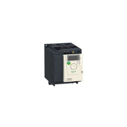
Altivar Machine ATV12 is an offer of variable speed drives for commercial equipment and simple machines. It works at a rated power up to 0.75kW / 1hp and a rated voltage from 100V to 120V AC. It is designed with heatsink for normal environments and fan-cooled enclosure. It has advanced PID and catch on the fly functions, basic cabling, and easy motor control setting. Based on the needs, it can be delivered without heatsink, with embedded EMC filter, or as standard version. The Altivar 12 drive integrates as standard the Modbus communication protocol. This Altivar Machine ATV12 is designed for simple applications, in industry, commercial machines and HVAC machines such as conveyors, pumps, extractors, access barriers and treadmills. It conforms to IEC, UL and other international standards. SoMove software compatibility enables saving and transfering of configurations to spare drive, reducing maintenance downtime. It features an optimized application of power and torque for ventilation and pumping applications, this allows up to 30% energy savings.
Main
| Characteristic | Value(s) |
|---|---|
| Range of Product | Altivar 12 |
| Product or Component Type | Variable speed drive |
| Product Specific Application | Simple machine |
| Mounting Mode | Cabinet mount |
| Communication Port Protocol | Modbus |
| Supply frequency | 50/60 Hz +/- 5 % |
| [Us] rated supply voltage | 100...120 V - 15...10 % |
| nominal output current | 4.2 A |
| Motor power kW | 0.75 kW |
| Maximum Horse Power Rating | 1 hp |
| EMC filter | Without EMC filter |
| IP degree of protection | IP20 |
| Maximum Horse Power Rating | 1 hp |
Complementary
| Characteristic | Value(s) |
|---|---|
| Discrete input number | 4 |
| Discrete output number | 2 |
| Analogue input number | 1 |
| Analogue output number | 1 |
| Relay output number | 1 |
| Physical interface | 2-wire RS 485 |
| Connector Type | 1 RJ45 |
| Continuous output current | 4.2 A 4 kHz |
| Method of access | Server Modbus serial |
| Speed drive output frequency | 0.5â¦400 Hz |
| Speed range | 1â¦20 |
| Sampling duration | 20 ms +/- 1 ms logic input 10 ms analogue input |
| Linearity error | +/- 0.3 % of maximum value analogue input |
| Frequency resolution | Analog input converter A/D, 10 bits Display unit 0.1 Hz |
| Time constant | 20 ms +/- 1 ms for reference change |
| Transmission Rate | 9.6 kbit/s 19.2 kbit/s 38.4 kbit/s |
| Transmission frame | RTU |
| Number of addresses | 1â¦247 |
| Data format | 8 bits, configurable odd, even or no parity |
| Communication service | Read holding registers (03) 29 words Write single register (06) 29 words Write multiple registers (16) 27 words Read/write multiple registers (23) 4/4 words Read device identification (43) |
| Type of polarization | No impedance |
| 4 quadrant operation possible | False |
| Asynchronous motor control profile | Voltage/frequency ratio (V/f) Quadratic voltage/frequency ratio Sensorless flux vector control |
| Maximum output frequency | 4 kHz |
| Transient overtorque | 150â¦170 % of nominal motor torque depending on drive rating and type of motor |
| Acceleration and deceleration ramps | Linear from 0 to 999.9 s S U |
| Motor slip compensation | Preset in factory Adjustable |
| Switching frequency | 2...16 kHz adjustable 4...16 kHz with derating factor |
| Nominal switching frequency | 4 kHz |
| Braking to standstill | By DC injection |
| Brake chopper integrated | False |
| Line current | 18.9 A 100 V heavy duty) 15.7 A 120 V heavy duty) |
| Maximum Input Current per Phase | 15.7 A |
| Maximum output voltage | 240 V |
| Apparent power | 1.9 kVA 240 V heavy duty) |
| Maximum transient current | 6.3 A 60 s heavy duty) 6.9 A 2 s heavy duty) |
| Network Frequency | 50-60 Hz |
| Relative symmetric network frequency tolerance | 5 % |
| Prospective line Isc | 1 kA |
| Base load current at high overload | 4.2 A |
| Power dissipation in W | Forced cooling 48.0 W |
| With safety function Safely Limited Speed (SLS) | False |
| With safety function Safe brake management (SBC/SBT) | False |
| With safety function Safe Operating Stop (SOS) | False |
| With safety function Safe Position (SP) | False |
| With safety function Safe programmable logic | False |
| With safety function Safe Speed Monitor (SSM) | False |
| With safety function Safe Stop 1 (SS1) | False |
| With sft fct Safe Stop 2 (SS2) | False |
| With safety function Safe torque off (STO) | False |
| With safety function Safely Limited Position (SLP) | False |
| With safety function Safe Direction (SDI) | False |
| Protection type | Line supply overvoltage Line supply undervoltage Overcurrent between output phases and earth Overheating protection Short-circuit between motor phases Against input phase loss in three-phase Thermal motor protection via the drive by continuous calculation of I²t |
| Tightening torque | 10.6 lbf.in (1.2 N.m) |
| Insulation | Electrical between power and control |
| Quantity per Set | Set of 1 |
| Width | 4.1 in (105 mm) |
| Height | 5.6 in (142 mm) |
| Depth | 6.1 in (156.2 mm) |
| Product Weight | 2.9 lb(US) (1.3 kg) |

10.4 Touch Panel

Configurable safe small controllers PNOZmulti 2, base unit, expandable, 20 safe digital inputs, 4 safe semiconductor outputs.

PNOZsigma safety relay (standalone), inputs: 1/2-channel wiring with/without detection of shorts across contacts, manual/automatic start, outputs: 2 N/O, 2 N/O t-d (t = 0.04 - 300 s), 1 SC, UB = 24 V DC, width: 22.5 mm, plug-in spring-loaded terminals, monitoring of E-STOP, safety gates, light curtain.