
 1 year warranty

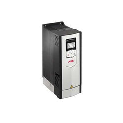
15HP, 3 Phase, 380-480V, Nema 12 Enclosure, Variable Frequency Drive
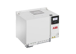
ACS380-040S-050A-4 PN: 22kW, IN: 50A; The ACS380 machinery drive comes in several variants, ensuring seamless integration into machines and connecting perfectly to automation systems. It’s a great fit for industries such as food and beverage, material handling and textile. Typical applications include mixers, conveyors, EOT and tower cranes, extruders, and textile machinery. With the integrated functional safety features, the ACS380 drive can be also part of the machine’s safety system via PROFIsafe over PROFINET, ensuring the motor is safely stopped when required. In addition, the drive’s software can be easily customized with adaptive programming to match any specific application requirements.

Specifications
Model |
GT2-P12K*1 |
|||
Detection system |
Scale Shot System II, absolute (no tracking errors) type |
|||
Measuring range |
12 mm 0.47" |
|||
Resolution |
0.1 μm 0.004 Mil |
|||
Indicated accuracy |
1 µm 0.04 Mil (p-p)*2 |
|||
Measuring force |
Downward mounting |
1.0 N*3 |
||
Side mounting |
0.95 N*3 |
|||
Upward mounting |
0.9 N*3 |
|||
Sampling cycle |
4 ms |
|||
Mechanical response |
10 Hz*2 |
|||
Operation indicator light |
2-color LED (red, green) |
|||
Environmental resistance |
Enclosure rating |
IP67G (JIS)*4, IP67 (IEC), NEMA Type 13*4 |
||
Ambient temperature |
-10 to +55 °C 14 to 131 °F (No freezing) |
|||
Relative humidity |
35 to 85 % RH (No condensation) |
|||
Vibration resistance |
10 to 55 Hz, Double amplitude 1.5 mm 0.06", 2 hours in each of the X, Y, and Z directions |
|||
Shock resistance |
1,000 m/s2 (IEC60068-2-27) |
|||
Materials |
Main body |
Main body case: SUS 303, Status indicator: PET, Sensor head-relay connector cable: PUR, Relay connector: PBT |
||
Dust boot |
NBR |
|||
Contact |
SUS304, cemented tungsten carbide*5 |
|||
Sensor head cable |
Optional (connect to relay connector) |
|||
Weight |
Approx. 35 g (excluding cable)*6 |
|||
*1 Note: You may not be able to connect the sensor head to the amplifier unit depending on when the amplifier unit was purchased. For details, contact your local sales office. | ||||

Specifications
Model |
LV-NH110 |
|||
Type |
Area thrubeam, High power |
|||
FDA (CDRH) Part 1040.10 |
Class 1 Laser Product |
|||
IEC 60825-1 | ||||
Light source |
Visible red semiconductor laser, Wavelength: 660 nm |
|||
Detecting |
MEGA |
2000 mm 78.74" |
||
ULTRA | ||||
SUPER | ||||
TURBO | ||||
FINE | ||||
HSP | ||||
Environmental resistance |
Ambient temperature |
-10 to +55 °C 14 to 131 °F (No freezing) |
||
Relative humidity |
35 to 85 % RH (No condensation) |
|||
Material |
Case |
Glass reinforced plastic |
||
Lens cover |
Transmitter: Glass, Receiver: Polyarylate |
|||
Weight |
Approx. 75 g |
|||
| Product | |
| Article Number (Market Facing Number) | 6ES71384CA010AA0 | 6ES71384CA010AA0 |
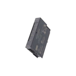
| Product Description | SIMATIC DP, POWER MODULE PM-E FOR ET 200S; 24V DC test pmi |
| Product family | Not available |
| Product Lifecycle (PLM) | PM410:Product cancellation |
| Additional Product Information | |
| EAN | 4025515072379 |
| UPC | 662643231328 |
| Commodity Code | 85389091 |
| LKZ_FDB/ CatalogID | ST76 |
| Product Group | 4467 |
| Group Code | R151 |
| Country of origin | China |
| SCIP number | Not available |
| Delivery information | |
| Net Weight (lb) | 0.086 lb |
| Package size unit of measure | Inch |
| Packaging Quantity | 1 |

J DRIVE, 480V 3-PH, 4.1/3.4A

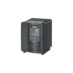
Inverter Drive 24 380...480V Ac, 11Kw

| Product | |
| Article Number (Market Facing Number) | 6SL32101KE188AF1 | 6SL32101KE188AF1 |
| Product Description | SINAMICS G120C rated power 3AC380-480V +10/-20% 47-63Hz low overload: 4,0kW at 150% 3s, 110% 57s, 100% 240s high overload: 3,0kW at 200% 3s, 150% 57s, 100% 240s integrated filter class A external 24V I/O interface: 6DI, 2DO,1AI,1AO, 1Mot_t Safe Torque Off integrated Fieldbus: PROFINET-PN Protection: IP20/ UL OPEN TYPE Size: FSA 196X73X200(HXWXD) |
| Product family | Ordering Data Overview |
| Product Lifecycle (PLM) | PM300:Active Product |
| Additional Product Information | |
| EAN | 4042948663837 |
| UPC | 887621143961 |
| Commodity Code | 85044095 |
| LKZ_FDB/ CatalogID | D11.1SD |
| Product Group | 5673 |
| Group Code | R220 |
| Country of origin | Great Britain |
| SCIP number | Not available |
| Delivery information | |
| Net Weight (lb) | 5.071 lb |
| Package size unit of measure | Inch |
| Packaging Quantity | 1 |

| Product | |
| Article Number (Market Facing Number) | 6ES75163FP030AB0 |
| Product Description | |
| Product family | CPU 1516F-3 PN/DP |
| Product Lifecycle (PLM) | PM300:Active Product |
| Additional Product Information | |
| EAN | 4047623412441 |
| UPC | 195125383890 |
| Commodity Code | 85371091 |
| LKZ_FDB/ CatalogID | ST73 |
| Product Group | 4526 |
| Group Code | R152 |
| Country of origin | Germany |
| SCIP number | 2bd8d8fd-e8c8-442a-9efa-cfa43d4973e5 |
| Delivery information | |
| Net Weight (lb) | 1.153 lb |
| Package size unit of measure | Inch |
| Packaging Quantity | 1 |

| Product | |
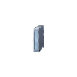
| Article Number (Market Facing Number) | 6ES75111AL030AB0 | 6ES75111AL030AB0 |
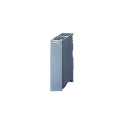
| Product Description | SIMATIC S7-1500, CPU 1511-1 PN, central processing unit with work memory 300 KB for program and 1.5 MB for data, 1st interface: PROFINET IRT with 2-port switch, 6 ns bit performance, SIMATIC Memory Card required |
| Product family | CPU 1511-1 PN |
| Product Lifecycle (PLM) | PM300:Active Product |
| Additional Product Information | |
| EAN | 4047623412458 |
| UPC | 195125370302 |
| Commodity Code | 85371091 |
| LKZ_FDB/ CatalogID | ST73 |
| Product Group | 4500 |
| Group Code | R132 |
| Country of origin | Germany |
| SCIP number | 45b8ea55-80c8-4250-a0d9-ec3af091c834 |
| Delivery information | |
| Net Weight (lb) | 0.840 lb |
| Package size unit of measure | Inch |
| Packaging Quantity | 1 |
| Product | |
| Article Number (Market Facing Number) | 3TK28060BB4 | 3TK28060BB4 |
| Product Description | !!! Phased-out product. The successor series is 3SK. Contactor safety combination for safety circuits Enabling and signaling circuit 5 NO+1 NC with self-latching mechanism K1 DC operation 24 V DC |
| Product family | Not available |
| Product Lifecycle (PLM) | PM490:Start of final year of support |
| Additional Product Information | |
| EAN | 4011209269521 |
| UPC | 754554407067 |
| Commodity Code | 85364190 |
| LKZ_FDB/ CatalogID | NSE |
| Product Group | 5837 |
| Group Code | R711 |
| Country of origin | Czech Republic |
| SCIP number | Not available |
| Delivery information | |
| Net Weight (lb) | 2.061 lb |
| Package size unit of measure | Inch |
| Packaging Quantity | 1 |

| Product | |
| Article Number (Market Facing Number) | 6ES75901AC400AA0 | 6ES75901AC400AA0 |
| Product Description | SIMATIC S7-1500, mounting rail 245 mm (approx. 9.6 inch); incl. grounding screw, integrated DIN rail for mounting of incidentals such as terminals, automatic circuit breakers and relays |
| Product family | Mounting rail |
| Product Lifecycle (PLM) | PM300:Active Product |
| Additional Product Information | |
| EAN | 4047623404767 |
| UPC | 804766082764 |
| Commodity Code | 76169990 |
| LKZ_FDB/ CatalogID | ST73 |
| Product Group | 4504 |
| Group Code | R151 |
| Country of origin | Germany |
| SCIP number | Not available |
| Delivery information | |
| Net Weight (lb) | 1.265 lb |
| Package size unit of measure | Inch |
| Packaging Quantity | 1 |
| Product | |
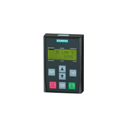
| Article Number (Market Facing Number) | 6SL32550AA004CA1 | 6SL32550AA004CA1 |
| Product Description | SINAMICS G120 Basic Operator Panel (BOP-2) |
| Product family | Ordering Data Overview |
| Product Lifecycle (PLM) | PM300:Active Product |
| Additional Product Information | |
| EAN | 4019169458085 |
| UPC | Not available |
| Commodity Code | 85049090 |
| LKZ_FDB/ CatalogID | D11.1SD |
| Product Group | 9791 |
| Group Code | R220 |
| Country of origin | Great Britain |
| SCIP number | Not available |
| Delivery information | |
| Net Weight (lb) | 0.309 lb |
| Package size unit of measure | Inch |
| Packaging Quantity | 1 |

| Product | |
| Article Number (Market Facing Number) | 6AV21818XP000AX0 | 6AV21818XP000AX0 |
| Product Description | SIMATIC SD memory card 2 GB secure digital card for devices with corresponding slot, scope of supply: 1 memory card |
| Product family | Storage media |
| Product Lifecycle (PLM) | PM300:Active Product |
| Additional Product Information | |
| EAN | 4025515080039 |
| UPC | 040892786194 |
| Commodity Code | 85235110 |
| LKZ_FDB/ CatalogID | ST80.1Q |
| Product Group | 2260 |
| Group Code | R141 |
| Country of origin | Germany |
| SCIP number | Not available |
| Delivery information | |
| Net Weight (lb) | 0.040 lb |
| Package size unit of measure | Inch |
| Packaging Quantity | 1 |

| Product | |
| Article Number (Market Facing Number) | 6ES72411CH301XB0 | 6ES72411CH301XB0 |
| Product Description | SIMATIC S7-1200, Communication Board CB 1241, RS485, terminal block, supports Freeport |
| Product family | CB 1241 RS485 communication board |
| Product Lifecycle (PLM) | PM300:Active Product |
| Additional Product Information | |
| EAN | 6940408100930 |
| UPC | 040892696707 |
| Commodity Code | 85176200 |
| LKZ_FDB/ CatalogID | ST72 |
| Product Group | 4510 |
| Group Code | R132 |
| Country of origin | China |
| SCIP number | Not available |
| Delivery information | |
| Net Weight (lb) | 0.068 lb |
| Package size unit of measure | Inch |
| Packaging Quantity | 1 |
| Product | |
| Article Number (Market Facing Number) | 6ES71344GB110AB0 | 6ES71344GB110AB0 |
| Product Description | *** Spare part *** SIMATIC DP, Electronics module f. ET200S, 2AI Standard I-4DMU 15 mm width, +/-20mA; 13 bit+sign 4.. 20mA; 12-bit for 4-wire transmitter Cycle time 65 ms/channel with SF LED (group fault) |
| Product family | Not available |
| Product Lifecycle (PLM) | PM410:Product cancellation |
| Additional Product Information | |
| EAN | 4025515072430 |
| UPC | 662643231397 |
| Commodity Code | 85389091 |
| LKZ_FDB/ CatalogID | ST76 |
| Product Group | 4467 |
| Group Code | R151 |
| Country of origin | China |
| SCIP number | Not available |
| Delivery information | |
| Net Weight (lb) | 0.097 lb |
| Package size unit of measure | Inch |
| Packaging Quantity | 1 |
| Product | |
| Article Number (Market Facing Number) | 6ES75050KA000AB0 | 6ES75050KA000AB0 |
| Product Description | SIMATIC S7-1500, System power supply PS 25W 24 V DC, supplies the backplane bus of the S7-1500 with operating voltage |
| Product family | System power supplies |
| Product Lifecycle (PLM) | PM300:Active Product |
| Additional Product Information | |
| EAN | 4025515079897 |
| UPC | 887621139629 |
| Commodity Code | 85044095 |
| LKZ_FDB/ CatalogID | ST73 |
| Product Group | 4500 |
| Group Code | R132 |
| Country of origin | Germany |
| SCIP number | Not available |
| Delivery information | |
| Net Weight (lb) | 0.785 lb |
| Package size unit of measure | Inch |
| Packaging Quantity | 1 |
| Product | |
| Article Number (Market Facing Number) | 6SE64001PB000AA0 | 6SE64001PB000AA0 |
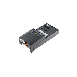
| Product Description | ***spare part*** MICROMASTER 4 PROFIBUS module For mechanical reasons, for MM4 FX/GX the plug 6GK1500-0EA02 must be used |
| Product family | Not available |
| Product Lifecycle (PLM) | PM410:Product cancellation |
| Additional Product Information | |
| EAN | 4019169447287 |
| UPC | 662643429206 |
| Commodity Code | 85049090 |
| LKZ_FDB/ CatalogID | DA51-A |
| Product Group | 9848 |
| Group Code | R2S3 |
| Country of origin | Great Britain |
| SCIP number | c3c52f35-4698-4009-8331-9292b80c5a23 |
| Delivery information | |
| Net Weight (lb) | 0.661 lb |
| Package size unit of measure | Inch |
| Packaging Quantity | 1 |

| Product | |
| Article Number (Market Facing Number) | 6ES75121SK010AB0 | 6ES75121SK010AB0 |
| Product Description | *** spare part *** SIMATIC DP, CPU 1512SP F-1 PN for ET 200SP, central processing unit with work memory 300 KB for program and 1 MB for data, 1st interface: PROFINET IRT with 3-port switch, 48 ns bit performance, SIMATIC Memory Card required, BusAdapter required for port 1 and 2 |
| Product family | Not available |
| Product Lifecycle (PLM) | PM410:Product cancellation |
| Additional Product Information | |
| EAN | 4047623406037 |
| UPC | 804766166563 |
| Commodity Code | 85371091 |
| LKZ_FDB/ CatalogID | ST76 |
| Product Group | 4A7E |
| Group Code | R152 |
| Country of origin | Germany |
| SCIP number | Not available |
| Delivery information | |
| Net Weight (lb) | 0.862 lb |
| Package size unit of measure | Inch |
| Packaging Quantity | 1 |
| Product | |
| Article Number (Market Facing Number) | 6SE64402AD222BA1 | 6SE64402AD222BA1 |
| Product Description | |
| Product family | Not available |
| Product Lifecycle (PLM) | PM410:Product cancellation |
| Additional Product Information | |
| EAN | 4019169450379 |
| UPC | 783087635845 |
| Commodity Code | 85044095 |
| LKZ_FDB/ CatalogID | DA51-E |
| Product Group | 9848 |
| Group Code | R2S3 |
| Country of origin | Great Britain |
| SCIP number | Not available |
| Delivery information | |
| Net Weight (lb) | 7.496 lb |
| Package size unit of measure | Inch |
| Packaging Quantity | 1 |

| Product | |
| Article Number (Market Facing Number) | 6SL32101KE238AF1 | 6SL32101KE238AF1 |
| Product Description | SINAMICS G120C rated power 3AC380-480V +10/-20% 47-63Hz low overload: 18,5kW at 150% 3s, 110% 57s, 100% 240s high overload: 15,0kW at 200% 3s, 150% 57s, 100% 240s integrated filter class A external 24V I/O interface: 6DI, 2DO,1AI,1AO, 1Mot_t Safe Torque Off integrated Fieldbus: PROFINET-PN Protection: IP20/ UL OPEN TYPE Size: FSC 295x140x205 (HXWXD) |
| Product family | Ordering Data Overview |
| Product Lifecycle (PLM) | PM300:Active Product |
| Additional Product Information | |
| EAN | 4042948663882 |
| UPC | 887621144036 |
| Commodity Code | 85044095 |
| LKZ_FDB/ CatalogID | D11.1SD |
| Product Group | 5673 |
| Group Code | R220 |
| Country of origin | Great Britain |
| SCIP number | Not available |
| Delivery information | |
| Net Weight (lb) | 12.125 lb |
| Package size unit of measure | Inch |
| Packaging Quantity | 1 |

| Product | |
| Article Number (Market Facing Number) | 6SL31000BE255AB0 | 6SL31000BE255AB0 |
| Product Description | SINAMICS S120 ACTIVE INTERFACE MODULE FOR 55KW ACTIVE LINE MODULE INPUT: 3AC 380-480V, 50/60HZ |
| Product family | Ordering Data Overview |
| Product Lifecycle (PLM) | PM300:Active Product |
| Additional Product Information | |
| EAN | 4042948662953 |
| UPC | 662643432763 |
| Commodity Code | 85363030 |
| LKZ_FDB/ CatalogID | D21MC |
| Product Group | 9617 |
| Group Code | R220 |
| Country of origin | Germany |
| SCIP number | ef578b0a-7ea7-48d5-a8df-68a002a67078 |
| Delivery information | |
| Net Weight (lb) | 52.911 lb |
| Package size unit of measure | Not available |
| Packaging Quantity | 1 |
| Product | |
| Article Number (Market Facing Number) | 6ES75225HH000AB0 | 6ES75225HH000AB0 |
| Product Description | SIMATIC S7-1500, digital output module DQ 16x 230V AC/2A ST; relay 16 channels in groups of 2; 4 A per group; switching cycle counter for integrated relay, diagnostics; substitute value: the module supports the safety-oriented shutdown of load groups up to SIL1 according to EN IEC 62061:2021 and Category 2 / PL c according to EN ISO 13849-1:2015. front connector (screw terminals or push-in) to be ordered separately |
| Product family | SM 522 digital output modules |
| Product Lifecycle (PLM) | PM300:Active Product |
| Additional Product Information | |
| EAN | 4047623404187 |
| UPC | 804766137877 |
| Commodity Code | 85389091 |
| LKZ_FDB/ CatalogID | ST73 |
| Product Group | 4501 |
| Group Code | R151 |
| Country of origin | Germany |
| SCIP number | Not available |
| Delivery information | |
| Net Weight (lb) | 0.822 lb |
| Package size unit of measure | Inch |
| Packaging Quantity | 1 |
| Product | |
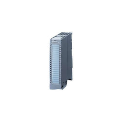
| Article Number (Market Facing Number) | 6ES75317NF100AB0 | 6ES75317NF100AB0 |
| Product Description | SIMATIC S7-1500 Analog input module AI 8xU/I HS, 16 bit resolution, Accuracy 0.3% 8 channels in groups of 8; Common mode voltage 10 V; Diagnostics; Hardware interrupts 8 channels in 0.0625 ms Oversampling; Delivery including infeed element, shield bracket and shield terminal: Front connector (screw terminals or push-in) to be ordered separately |
| Product family | SM 531 analog input modules |
| Product Lifecycle (PLM) | PM300:Active Product |
| Additional Product Information | |
| EAN | 4025515080145 |
| UPC | 887621139155 |
| Commodity Code | 85389091 |
| LKZ_FDB/ CatalogID | ST73 |
| Product Group | 4501 |
| Group Code | R151 |
| Country of origin | Germany |
| SCIP number | Not available |
| Delivery information | |
| Net Weight (lb) | 0.924 lb |
| Package size unit of measure | Inch |
| Packaging Quantity | 1 |