
 1 year warranty


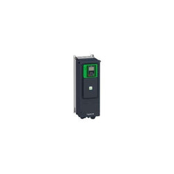
This Altivar Process ATV600 variable speed drive can feed 3-phase synchronous and asynchronous power motors. It features 3 built-in RJ45 communication ports as standard, 1 Ethernet port, 2 serial ports. It works at a rated supply voltage from 380V to 480V AC. This drive provides up to 30% energy saving when on standby due to the innovative ââStop and Goââoperation without additional costs. It is suitable for motors with power rating up to 15kW / 20hp for applications requiring slight overload (up to 120%). It is suitable for motors with power rating up to 11kW / 15hp for applications requiring significant overload (up to 150%). It weighs 19.6kg and its dimensions are, 264mm wide, 678mm high, 299mm deep. This drive is focused on fluids management processing and energy saving, it offers extensive flexibility in water and wastewater, mining, minerals and metals, oil and gas and food and beverage applications. Accessories (fan kit, graphic display terminal) and options (I/O expansion modules, communication modules, EMC input filters) are available with Altivar Process ATV600 drives, depending on the drive rating. It is designed to be mounted in vertical position (+/- 10 °) on a wall. This new concept of drives meets the major needs of process and utilities in terms of equipment efficiency and total cost of ownership by supporting the energy management, asset management and also the overall performance of the process.
Main
| Characteristic | Value(s) |
|---|---|
| Range of product | Altivar Process ATV600 |
| Product specific application | Process and utilities |
| Product or component type | Variable speed drive |
| Variant | Standard version |
| Device short name | ATV650 |
| Mounting mode | Wall mount |
| Communication port protocol | Modbus serial Ethernet Ethernet |
| [Us] rated supply voltage | 380...480 V - 15...10 % |
| [Us] rated supply voltage | 380...480 V |
| Relative symmetric mains voltage tolerance | 10 % |
| Relative symmetric network frequency tolerance | 5 % |
| nominal output current | 31.7 A |
| IP degree of protection | IP55 |
| Product destination | Asynchronous motors Synchronous motors |
| EMC filter | Integrated with 50 m conforming to IEC 61800-3 category C2 Integrated with 150 m conforming to IEC 61800-3 category C3 |
| IP degree of protection | IP55 conforming to IEC 60529 IP55 conforming to IEC 61800-5-1 |
| type of cooling | Forced convection |
| Supply frequency | 50...60 Hz - 5...5 % |
| Motor power kW | 11 kW (heavy duty) 15 kW (normal duty) |
| Motor power hp | 10 hp heavy duty 20 hp normal duty |
| Line current | 17 A at 480 V (normal duty) 14.1 A at 380 V (heavy duty) 12.5 A at 480 V (heavy duty) 27 A at 380 V (normal duty) |
| Continuous output current | 16.5 A at 4 kHz for heavy duty 31.7 A at 4 kHz for normal duty |
| Speed drive output frequency | 0.1â¦500 Hz |
| Safety function | STO (safe torque off) SIL 3 |
| Option card | Slot A: communication module, PROFINET Slot A: communication module, DeviceNet Slot A: communication module, Modbus TCP/EtherNet/IP Slot A: communication module, CANopen daisy chain RJ45 Slot A: communication module, CANopen SUB-D 9 Slot A: communication module, CANopen screw terminals Slot A/slot B: digital and analog I/O extension module Slot A/slot B: output relay extension module Slot A: communication module, Ethernet IP/Modbus TCP/MD-Link Communication module, BACnet MS/TP Communication module, Ethernet Powerlink Slot A: communication module, Profibus DP V1 |
Complementary
| Characteristic | Value(s) |
|---|---|
| Discrete input number | 8 |
| Discrete input type | DI7, DI8 programmable as pulse input: 0â¦30 kHz, 24 V DC (<= 30 V) |
| Discrete input logic | 16 preset speeds |
| Discrete output number | 0 |
| Discrete output type | Relay outputs R1A, R1B, R1C 250 V AC 3000 mA Relay outputs R1A, R1B, R1C 30 V DC 3000 mA Relay outputs R2A, R2C 250 V AC 5000 mA Relay outputs R2A, R2C 30 V DC 5000 mA Relay outputs R3A, R3C 250 V AC 5000 mA Relay outputs R3A, R3C 30 V DC 5000 mA |
| Analogue input number | 3 |
| Analogue input type | AI1, AI2, AI3 software-configurable voltage: 0...10 V DC, impedance: 31.5 kOhm, resolution 12 bits AI1, AI2, AI3 software-configurable current: 0...20 mA, impedance: 250 Ohm, resolution 12 bits AI2 voltage analog input: - 10...10 V DC, impedance: 31.5 kOhm, resolution 12 bits |
| Analogue output number | 2 |
| Analogue output type | Software-configurable voltage AQ1, AQ2: 0...10 V DC impedance 470 Ohm, resolution 10 bits Software-configurable current AQ1, AQ2: 0...20 mA, resolution 10 bits Software-configurable current DQ-, DQ+: 30 V DC Software-configurable current DQ-, DQ+: 100 mA |
| Relay output number | 3 |
| Relay output type | Configurable relay logic R2: sequence relay NO electrical durability 100000 cycles Configurable relay logic R3: sequence relay NO electrical durability 100000 cycles Configurable relay logic R1: fault relay NO/NC electrical durability 100000 cycles |
| Maximum switching current | Relay output R1, R2, R3 on resistive load, cos phi = 1: 3 A at 30 V DC Relay output R1, R2, R3 on inductive load, cos phi = 0.4 and L/R = 7 ms: 2 A at 250 V AC Relay output R1, R2, R3 on inductive load, cos phi = 0.4 and L/R = 7 ms: 2 A at 30 V DC Relay output R1, R2, R3 on resistive load, cos phi = 1: 3 A at 250 V AC |
| Minimum switching current | Relay output R1, R2, R3: 5 mA at 24 V DC |
| Network number of phases | 3 phases |
| Physical interface | Ethernet 2-wire RS 485 |
| Method of access | Slave Modbus TCP |
| Transmission rate | 10, 100 Mbits 4800 bps, 9600 bps, 19200 bps, 38.4 Kbps |
| Transmission frame | RTU |
| Output voltage | <= power supply voltage |
| Permissible temporary current boost | 1.5 x In during 60 s (heavy duty) 1.1 x In during 60 s (normal duty) |
| Data format | 8 bits, configurable odd, even or no parity |
| Type of polarization | No impedance |
| Frequency resolution | Analog input: 0.012/50 Hz Display unit: 0.1 Hz |
| Electrical connection | Motor: screw terminal 6...10 mm²/AWG 10...AWG 8 Line side: screw terminal 6 mm²/AWG 10 Control: removable screw terminals 0.5...1.5 mm²/AWG 20...AWG 16 |
| Connector type | RJ45 (on the remote graphic terminal) for Modbus serial RJ45 (on the remote graphic terminal) for Ethernet/Modbus TCP |
| Exchange mode | Half duplex, full duplex, autonegotiation Ethernet/Modbus TCP |
| Number of addresses | 1â¦247 for Modbus serial |
| Supply | Internal supply for reference potentiometer (1 to 10 kOhm): 10.5 V DC +/- 5 %, <10 mA, protection type: overload and short-circuit protection Internal supply for digital inputs and STO: 24 V DC (21â¦27 V), <200 mA, protection type: overload and short-circuit protection External supply for digital inputs: 24 V DC (19â¦30 V), <1.25 mA, protection type: overload and short-circuit protection |
| Local signalling | 3 LEDs (dual colour) for embedded communication status 4 LEDs (dual colour) for communication module status 1 LED (red) for presence of voltage 3 LEDs for local diagnostic |
| Input compatibility | DI5, DI6: discrete input level 1 PLC conforming to IEC 65A-68 STOA, STOB: discrete input level 1 PLC conforming to IEC 61131-2 DI1...DI6: discrete input level 1 PLC conforming to IEC 61131-2 |
| Discrete input logic | Positive logic (source) (DI1...DI8), < 5 V (state 0), > 11 V (state 1) Negative logic (sink) (DI1...DI8), > 16 V (state 0), < 10 V (state 1) |
| Sampling duration | 5 ms +/- 1 ms (DI5, DI6) - discrete input 5 ms +/- 0.1 ms (AI1, AI2, AI3) - analog input 10 ms +/- 1 ms (AO1) - analog output 2 ms +/- 0.5 ms (DI1...DI4) - discrete input |
| Accuracy | +/- 1 % AO1, AO2 for a temperature variation 60 °C analog output +/- 0.6 % AI1, AI2, AI3 for a temperature variation 60 °C analog input |
| Linearity error | AO1, AO2: +/- 0.2 % for analog output AI1, AI2, AI3: +/- 0.15 % of maximum value for analog input |
| Refresh time | Relay output (R1, R2, R3): 5 ms (+/- 0.5 ms) |
| Isolation | Between power and control terminals |
| Discrete and process manufacturing | Building - HVAC compressor centrifugal |
| Power range | 15â¦25 kW at 380â¦440 V 3 phases |
| Enclosure mounting | Wall mounted |
| 4 quadrant operation possible | False |
| Asynchronous motor control profile | Optimized torque mode Constant torque standard Constant torque standard |
| Synchronous motor control profile | Synchronous reluctance motor Permanent magnet motor |
| Maximum output frequency | 500 kHz |
| Acceleration and deceleration ramps | Linear adjustable separately from 0.01...9999 s |
| Motor slip compensation | Adjustable Not available in permanent magnet motor law Can be suppressed Not available in permanent magnet motor law |
| Switching frequency | 4...12 kHz with derating factor 2...12 kHz adjustable |
| Nominal switching frequency | 4 kHz |
| Braking to standstill | By DC injection |
| Brake chopper integrated | False |
| Maximum input current | 27.0 A |
| Maximum output voltage | 480.0 V |
| Apparent power | 10.4 kVA at 480 V (heavy duty) 19.4 kVA at 480 V (normal duty) |
| Maximum transient current | 24.8 A during 60 s (heavy duty) 34.9 A during 60 s (normal duty) |
| Network frequency | 50...60 Hz |
| Prospective line Isc | 50 kA |
| Base load current at high overload | 23.5 A |
| Base load current at low overload | 31.7 A |
| With safety function Safely Limited Speed (SLS) | False |
| With safety function Safe brake management (SBC/SBT) | False |
| With safety function Safe Operating Stop (SOS) | False |
| With safety function Safe Position (SP) | False |
| With safety function Safe programmable logic | False |
| With safety function Safe Speed Monitor (SSM) | False |
| With safety function Safe Stop 1 (SS1) | False |
| With sft fct Safe Stop 2 (SS2) | False |
| With safety function Safe torque off (STO) | True |
| With safety function Safely Limited Position (SLP) | False |
| With safety function Safe Direction (SDI) | False |
| Protection type | Safe torque off: motor Motor phase break: motor Thermal protection: drive Safe torque off: drive Overheating: drive Overcurrent between output phases and earth: drive Overload of output voltage: drive Short-circuit protection: drive Motor phase break: drive Overvoltages on the DC bus: drive Line supply overvoltage: drive Line supply undervoltage: drive Line supply phase loss: drive Overspeed: drive Break on the control circuit: drive Thermal protection: motor |
| Quantity per set | 1 |
| Width | 264 mm |
| Height | 678 mm |
| Depth | 299 mm |
| Product weight | 19.6 kg |

Main
| Characteristic | Value(s) |
|---|---|
| Range of Product | Lexium integrated drive |
| Product or Component Type | Motion integrated drive |
| Device short name | ILS |
| Motor Type | 3-phase stepper motor |
| Number of motor poles | 6 |
| Phase | Single phase |
| [Us] rated supply voltage | 36 V 24 V |
| Network type | DC |
| Communication interface | Pulse/direction 5 V without RS422, Integrated |
| Length | 4.01 in (101.9 mm) |
| Winding type | Medium speed of rotation and medium torque |
| Electrical Connection | Printed circuit board connector |
| Holding brake | Without |
| Gear box type | Without |
| Nominal speed | 1000 rpm 36 V 500 rpm 24 V |
| Nominal torque | 3.98 lbf.in (0.45 N.m) |
| Holding torque | 4.51 lbf.in (0.51 N.m) |
Complementary
| Characteristic | Value(s) |
|---|---|
| Mounting Support | Flange |
| Motor flange size | 2.2 in (57 mm) |
| Number of motor stacks | 1 |
| Centring collar diameter | 1.5 in (38.1 mm) |
| centring collar depth | 0.06 in (1.6 mm) |
| Number of mounting holes | 4 |
| Mounting holes diameter | 0.2 in (5.2 mm) |
| Circle diameter of the mounting holes | 2.6 in (66.6 mm) |
| Feedback type | Index pulse |
| Shaft end | Untapped |
| Second shaft | Without second shaft end |
| Shaft diameter | 0.25 in (6.35 mm) |
| Shaft length | 0.8 in (21 mm) |
| Supply voltage limits | 18â¦40 V |
| Current consumption | 3500 mA maximum continuous |
| Associated fuse rating | 10 A |
| Input/output type | 4 signals (each be used as input or output) |
| Voltage state 0 guaranteed | -3...4.5 V |
| Voltage state 1 guaranteed | 15...30 V |
| Discrete input current | 10 mA at 24 V safety input |
| Discrete output voltage | 23...25 V |
| Maximum switching current | 100 mA per output 200 mA total |
| Protection Type | Safe torque off Overload of output voltage Short circuit of the output voltage |
| Peak stall torque | 3.98 lbf.in (0.45 N.m) |
| Continuous stall torque | 3.98 lbf.in (0.45 N.m) |
| Speed feedback resolution | 1.8°, 0.9°, 0.72°, 0.36°, 0.18°, 0.09°, 0.072°, 0.036° 200, 400, 500, 1000, 2000, 4000, 5000, 10000 steps |
| Accuracy error | +/- 6 arc min |
| Rotor inertia | 0.1 kg.cm² |
| Maximum mechanical speed | 3000 rpm |
| Maximum radial force Fr | 24 N |
| Maximum axial force Fa | 100 N tensile force) 8.4 N force pressure) |
| Service life in hours | 20000 h bearing |
| Marking | CE |
| type of cooling | Natural convection |
| Product Weight | 2.9 lb(US) (1.3 kg) |
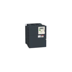
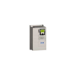
This Altivar Process ATV900 variable speed drive can feed 3-phase synchronous and asynchronous power motors. It is suitable for motors with power rating up to 18.5kW/25hp for applications requiring slight overload (up to 120%). It is suitable for motors with power rating up to 15kW/20hp for applications requiring significant overload (up to 150%). It works at a rated supply voltage from 380V to 480V AC. This variable speed / frequency drive (VSD / VFD) is specifically designed for industrial processes. In the following market segments, oil and gas, mining, minerals and metals, food and beverage water and wastewater. It offers high motor performance on any motor and total control of any kind of coupling in master/slave applications. Network services help ensure operation continuity even in case of connection breakdown. Web server and data logging help reduce downtime through fast troubleshooting and preventive maintenance. Its advanced connectivity, including EtherNet/IP and Modbus TCP, allows deep integration into automation architectures. It is designed to be mounted in vertical position (+/- 10 °) on a wall.
Main
| Characteristic | Value(s) |
|---|---|
| Range of product | Altivar Process ATV900 |
| Product specific application | Process for industrial |
| Product or component type | Variable speed drive |
| Variant | With braking chopper Standard version |
| Device application | Industrial application |
| Product destination | Asynchronous motors Synchronous motors |
| Network number of phases | 3 phases |
| Mounting mode | Wall mount |
| Continuous output current | 39.2 A at 4 kHz for normal duty 31.7 A at 4 kHz for heavy duty |
| Communication port protocol | EtherNet/IP Modbus TCP Modbus serial |
| Option card | Slot A: communication module for Profibus DP V1 Slot A: communication module for PROFINET Slot A: communication module for DeviceNet Slot A: communication module for EtherCAT Slot A: communication module for CANopen daisy chain RJ45 Slot A: communication module for CANopen SUB-D 9 Slot A: communication module for CANopen screw terminals Slot A/slot B/slot C: digital and analog I/O extension module Slot A/slot B/slot C: output relay extension module Slot B: 5/12 V digital encoder interface module Slot B: analog encoder interface module Slot B: resolver encoder interface module communication module for Ethernet Powerlink |
| [Us] rated supply voltage | 380...480 V - 15...10 % |
| [Us] rated supply voltage | 380...480 V |
| Relative symmetric mains voltage tolerance | 10 % |
| Relative symmetric network frequency tolerance | 5 % |
| nominal output current | 39.2 A |
| Motor power kW | 18.5 kW for normal duty 15.0 kW for heavy duty |
| EMC filter | Integrated With EMC plate option |
| IP degree of protection | IP55 |
| Degree of protection | UL type 1 |
Complementary
| Characteristic | Value(s) |
|---|---|
| Electrical connection | Control: screw terminal 0.5...1.5 mm²/AWG 20...AWG 16 Line side: screw terminal 10...16 mm²/AWG 8...AWG 6 Motor: screw terminal 10...16 mm²/AWG 8...AWG 6 DC bus: screw terminal 10...16 mm²/AWG 8...AWG 6 |
| Transmission rate | 10/100 Mbit/s for Ethernet IP/Modbus TCP 4.8, 9.6, 19.2, 38.4 kbit/s for Modbus serial |
| Exchange mode | Half duplex, full duplex, autonegotiation Ethernet IP/Modbus TCP |
| Data format | 8 bits, configurable odd, even or no parity for Modbus serial |
| Type of polarization | No impedance for Modbus serial |
| Number of addresses | 1â¦247 for Modbus serial |
| Supply | External supply for digital inputs: 24 V DC (19â¦30 V), <1.25 mA, protection type: overload and short-circuit protection Internal supply for reference potentiometer (1 to 10 kOhm): 10.5 V DC +/- 5 %, <10 mA, protection type: overload and short-circuit protection Internal supply for digital inputs and STO: 24 V DC (21â¦27 V), <200 mA, protection type: overload and short-circuit protection |
| Local signalling | Local diagnostic: 3 LED (mono/dual colour) Embedded communication status: 5 LED (dual colour) Communication module status: 2 LED (dual colour) Presence of voltage: 1 LED (red) |
| Input compatibility | DI1...DI8: discrete input level 1 PLC conforming to IEC 61131-2 DI7, DI8: pulse input level 1 PLC conforming to IEC 65A-68 STOA, STOB: discrete input level 1 PLC conforming to IEC 61131-2 |
| Discrete input logic | Positive logic (source) (DI1...DI8), < 5 V (state 0), > 11 V (state 1) Negative logic (sink) (DI1...DI8), > 16 V (state 0), < 10 V (state 1) Positive logic (source) (DI7, DI8), < 0.6 V (state 0), > 2.5 V (state 1) Positive logic (source) (STOA, STOB), < 5 V (state 0), > 11 V (state 1) |
| Sampling duration | 2 ms +/- 0.5 ms (DI1...DI8) - discrete input 5 ms +/- 1 ms (DI7, DI8) - pulse input 1 ms +/- 1 ms (AI1, AI2, AI3) - analog input 5 ms +/- 1 ms (AQ1, AQ2) - analog output |
| Accuracy | +/- 0.6 % AI1, AI2, AI3 for a temperature variation 60 °C analog input +/- 1 % AQ1, AQ2 for a temperature variation 60 °C analog output |
| Linearity error | AI1, AI2, AI3: +/- 0.15 % of maximum value for analog input AQ1, AQ2: +/- 0.2 % for analog output |
| Refresh time | Relay output (R1, R2, R3): 5 ms (+/- 0.5 ms) |
| Isolation | Between power and control terminals |
| Discrete input number | 10 |
| Discrete input type | DI1...DI8 programmable, 24 V DC (<= 30 V), impedance: 3.5 kOhm DI7, DI8 programmable as pulse input: 0â¦30 kHz, 24 V DC (<= 30 V) STOA, STOB safe torque off, 24 V DC (<= 30 V), impedance: > 2.2 kOhm |
| Discrete input logic | 16 preset speeds |
| Discrete output number | 2 |
| Discrete output type | Logic output DQ+ 0â¦1 kHz <= 30 V DC 100 mA Programmable as pulse output DQ+ 0â¦30 kHz <= 30 V DC 20 mA Logic output DQ- 0â¦1 kHz <= 30 V DC 100 mA |
| Analogue input number | 3 |
| Analogue input type | AI1, AI2, AI3 software-configurable voltage: 0...10 V DC, impedance: 30 kOhm, resolution 12 bits AI1, AI2, AI3 software-configurable current: 0...20 mA/4...20 mA, impedance: 250 Ohm, resolution 12 bits |
| Analogue output number | 2 |
| Analogue output type | Software-configurable voltage AQ1, AQ2: 0...10 V DC impedance 470 Ohm, resolution 10 bits Software-configurable current AQ1, AQ2: 0...20 mA impedance 500 Ohm, resolution 10 bits |
| Relay output number | 3 |
| Relay output type | Configurable relay logic R1: fault relay NO/NC electrical durability 100000 cycles Configurable relay logic R2: sequence relay NO electrical durability 1000000 cycles Configurable relay logic R3: sequence relay NO electrical durability 1000000 cycles |
| Maximum switching current | Relay output R1 on resistive load, cos phi = 1: 3 A at 250 V AC Relay output R1 on resistive load, cos phi = 1: 3 A at 30 V DC Relay output R1 on inductive load, cos phi = 0.4 and L/R = 7 ms: 2 A at 250 V AC Relay output R1 on inductive load, cos phi = 0.4 and L/R = 7 ms: 2 A at 30 V DC Relay output R2, R3 on resistive load, cos phi = 1: 5 A at 250 V AC Relay output R2, R3 on resistive load, cos phi = 1: 5 A at 30 V DC Relay output R2, R3 on inductive load, cos phi = 0.4 and L/R = 7 ms: 2 A at 250 V AC Relay output R2, R3 on inductive load, cos phi = 0.4 and L/R = 7 ms: 2 A at 30 V DC |
| Minimum switching current | Relay output R1, R2, R3: 5 mA at 24 V DC |
| Physical interface | Ethernet 2-wire RS 485 |
| Connector type | 2 RJ45 1 RJ45 |
| Method of access | Slave Modbus TCP |
| Transmission rate | 10, 100 Mbits 4.8 kbps 9600 bit/s 19200 bit/s |
| Transmission frame | RTU |
| Number of addresses | 1â¦247 |
| Data format | 8 bits, configurable odd, even or no parity |
| Type of polarization | No impedance |
| 4 quadrant operation possible | True |
| Asynchronous motor control profile | Optimized torque mode Constant torque standard Variable torque standard |
| Synchronous motor control profile | Permanent magnet motor Synchronous reluctance motor |
| Maximum output frequency | 599 Hz |
| Acceleration and deceleration ramps | Linear adjustable separately from 0.01...9999 s |
| Motor slip compensation | Automatic whatever the load Not available in permanent magnet motor law Can be suppressed Adjustable |
| Switching frequency | 2...16 kHz adjustable 4...16 kHz with derating factor |
| Nominal switching frequency | 4 kHz |
| Braking to standstill | By DC injection |
| Brake chopper integrated | True |
| Line current | 33.4 A at 380 V (normal duty) 27.7 A at 380 V (heavy duty) 28.9 A at 480 V (normal duty) 24.4 A at 480 V (heavy duty) |
| Maximum input current | 33.4 A |
| Maximum output voltage | 480.0 V |
| Apparent power | 24 kVA at 480 V (normal duty) 20.3 kVA at 480 V (heavy duty) |
| Maximum transient current | 47 A during 60 s (normal duty) 47.6 A during 60 s (heavy duty) |
| Network frequency | 50...60 Hz |
| Prospective line Isc | 50 kA |
| Base load current at high overload | 31.7 A |
| Base load current at low overload | 39.2 A |
| With safety function Safely Limited Speed (SLS) | True |
| With safety function Safe brake management (SBC/SBT) | True |
| With safety function Safe Operating Stop (SOS) | False |
| With safety function Safe Position (SP) | False |
| With safety function Safe programmable logic | False |
| With safety function Safe Speed Monitor (SSM) | False |
| With safety function Safe Stop 1 (SS1) | True |
| With sft fct Safe Stop 2 (SS2) | False |
| With safety function Safe torque off (STO) | True |
| With safety function Safely Limited Position (SLP) | False |
| With safety function Safe Direction (SDI) | False |
| Protection type | Thermal protection: motor Safe torque off: motor Motor phase break: motor Thermal protection: drive Safe torque off: drive Overheating: drive Overcurrent between output phases and earth: drive Overload of output voltage: drive Short-circuit protection: drive Motor phase break: drive Overvoltages on the DC bus: drive Line supply overvoltage: drive Line supply undervoltage: drive Line supply phase loss: drive Overspeed: drive Break on the control circuit: drive |
| Quantity per set | 1 |
| Width | 264 mm |
| Height | 678 mm |
| Depth | 299 mm |
| Product weight | 20.6 kg |
Main
| Characteristic | Value(s) |
|---|---|
| Range of product | Altivar |
| Product or component type | Variable speed drive |
| Product specific application | Simple machine Wire guiding |
| Component name | ATV31 |
| Assembly style | With heat sink |
| EMC filter | Without EMC filter |
| [Us] rated supply voltage | 200...240 V - 5...5 % |
| Supply frequency | 50...60 Hz - 5...5 % |
| Network number of phases | 3 phases |
| Motor power kW | 7.5 kW 4 kHz |
| Motor power hp | 10 hp 4 kHz |
| Line current | 40.9 A at 240 V 46.8 A at 200 V, Isc = 1 kA |
| Apparent power | 16.2 kVA |
| Prospective line Isc | 1 kA |
| Nominal output current | 33 A 4 kHz |
| Maximum transient current | 49.5 A for 60 s |
| Power dissipation in W | 388 W at nominal load |
| Asynchronous motor control profile | Sensorless flux vector control with PWM type motor control signal Factory set : constant torque |
| Analogue input number | 3 |
Complementary
| Characteristic | Value(s) |
|---|---|
| Product destination | Asynchronous motors |
| Supply voltage limits | 170â¦264 V |
| Network frequency | 47.5...63 Hz |
| Output frequency | 0.0005â¦0.5 kHz |
| Nominal switching frequency | 4 kHz |
| Switching frequency | 2...16 kHz adjustable |
| Speed range | 1â¦50 |
| Transient overtorque | 150â¦170 % of nominal motor torque |
| Braking torque | <= 150 % during 60 s with braking resistor 100 % with braking resistor continuously 150 % without braking resistor |
| Regulation loop | Frequency PI regulator |
| Motor slip compensation | Adjustable Suppressable Automatic whatever the load |
| Output voltage | <= power supply voltage |
| Electrical connection | Al1, Al2, Al3, AOV, AOC, R1A, R1B, R1C, R2A, R2B, LI1...LI6 terminal 2.5 mm² AWG 14 L1, L2, L3, U, V, W, PA, PB, PA/+, PC/- terminal 2.5 mm² AWG 14 |
| Tightening torque | Al1, Al2, Al3, AOV, AOC, R1A, R1B, R1C, R2A, R2B, LI1...LI6: 0.6 N.m L1, L2, L3, U, V, W, PA, PB, PA/+, PC/-: 0.8 N.m |
| Insulation | Electrical between power and control |
| Supply | Internal supply for logic inputs: 19...30 V 100 mA, protection type: overload and short-circuit protection Internal supply for reference potentiometer (2.2 to 10 kOhm): 10...10.8 V 10 mA, protection type: overload and short-circuit protection |
| Analogue input type | AI3 configurable current 0...20 mA, impedance: 250 Ohm AI1 configurable voltage 0...10 V, input voltage 30 V max, impedance: 30000 Ohm AI2 configurable voltage +/- 10 V, input voltage 30 V max, impedance: 30000 Ohm |
| Sampling duration | LI1...LI6: 4 ms discrete AI1, AI2, AI3: 8 ms analog |
| Response time | AOV, AOC 8 ms for analog R1A, R1B, R1C, R2A, R2B 8 ms for discrete |
| Linearity error | +/- 0.2 % for output |
| Analogue output number | 2 |
| Analogue output type | AOC configurable current: 0...20 mA, impedance: 800 Ohm, resolution: 8 bits AOV configurable voltage: 0...10 V, impedance: 470 Ohm, resolution: 8 bits |
| Discrete input logic | Positive logic (source) (LI1...LI6), < 5 V (state 0), > 11 V (state 1) Logic input not wired (LI1...LI4), < 13 V (state 1) Negative logic (source) (LI1...LI6), > 19 V (state 0) |
| Discrete output number | 2 |
| Discrete output type | Configurable relay logic: (R1A, R1B, R1C) 1 NO + 1 NC - 100000 cycles Configurable relay logic: (R2A, R2B) NC - 100000 cycles |
| Minimum switching current | R1-R2 10 mA at 5 V DC |
| Maximum switching current | R1-R2: 2 A at 250 V AC inductive load, cos phi = 0.4 and L/R = 7 ms R1-R2: 2 A at 30 V DC inductive load, cos phi = 0.4 and L/R = 7 ms R1-R2: 5 A at 250 V AC resistive load, cos phi = 1 and L/R = 0 ms R1-R2: 5 A at 30 V DC resistive load, cos phi = 1 and L/R = 0 ms |
| Discrete input number | 6 |
| Discrete input type | (LI1...LI6) programmable at 24 V, 0â¦100 mA for PLC, impedance: 3500 Ohm |
| Acceleration and deceleration ramps | Linear adjustable separately from 0.1 to 999.9 s S, U or customized |
| Braking to standstill | By DC injection |
| Protection type | Input phase breaks: drive Line supply overvoltage and undervoltage safety circuits: drive Line supply phase loss safety function, for three phases supply: drive Motor phase breaks: drive Overcurrent between output phases and earth (on power up only): drive Overheating protection: drive Short-circuit between motor phases: drive Thermal protection: motor |
| Insulation resistance | >= 500 mOhm 500 V DC for 1 minute |
| Display type | 1 LED (red) for drive voltage Four 7-segment display units for CANopen bus status |
| Time constant | 5 ms for reference change |
| Frequency resolution | Display unit: 0.1 Hz Analog input: 0.1...100 Hz |
| Connector type | 1 RJ45 for CANopen via VW3 CANTAP2 adaptor 1 RJ45 for Modbus |
| Physical interface | RS485 multidrop serial link for CANopen via VW3 CANTAP2 adaptor RS485 multidrop serial link for Modbus |
| Transmission frame | RTU for CANopen via VW3 CANTAP2 adaptor RTU for Modbus |
| Transmission rate | 10, 20, 50, 125, 250, 500 kbps or 1 Mbps for CANopen via VW3 CANTAP2 adaptor 4800, 9600 or 19200 bps for Modbus |
| Number of addresses | 1â¦127 for CANopen via VW3 CANTAP2 adaptor 1â¦247 for Modbus |
| Number of drive | 127 for CANopen via VW3 CANTAP2 adaptor 31 for Modbus |
| Marking | CE |
| Operating position | Vertical +/- 10 degree |
| Product weight | 6.4 kg |

Main
| Characteristic | Value(s) |
|---|---|
| Range of Product | Altivar |
| Product or Component Type | Variable speed drive |
| Product Specific Application | Simple machine |
| Component name | ATV31 |
| Assembly style | With heat sink |
| Variant | With drive order potentiometer |
| EMC filter | Integrated |
| [Us] rated supply voltage | 380...500 V - 5...5 % |
| Supply frequency | 50...60 Hz - 5...5 % |
| Phase | 3 phase |
| Motor power kW | 1.1 kW 4 kHz |
| Maximum Horse Power Rating | 1.5 hp 4 kHz |
| Line current | 3.7 A 500 V 4.9 A 380 V, Isc = 1 kA |
| Apparent power | 3.2 kVA |
| Prospective line Isc | 1 kA |
| Nominal output current | 3 A 4 kHz |
| Maximum transient current | 4.5 A 60 s |
| Power dissipation in W | 48 W at nominal load |
| Asynchronous motor control profile | Factory set : constant torque Sensorless flux vector control with PWM type motor control signal |
| Analogue input number | 4 |
Complementary
| Characteristic | Value(s) |
|---|---|
| Product destination | Asynchronous motors |
| Supply voltage limits | 323â¦550 V |
| Network Frequency | 47.5...63 Hz |
| Output frequency | 0.0005â¦0.5 kHz |
| Nominal switching frequency | 4 kHz |
| Switching frequency | 2...16 kHz adjustable |
| Speed range | 1â¦50 |
| Transient overtorque | 150â¦170 % of nominal motor torque |
| Braking torque | <= 150 % 60 s with braking resistor 100 % with braking resistor continuously 150 % without braking resistor |
| Regulation loop | Frequency PI regulator |
| Motor slip compensation | Automatic whatever the load Suppressable Adjustable |
| Output voltage | <= power supply voltage |
| Electrical connection | Al1, Al2, Al3, AOV, AOC, R1A, R1B, R1C, R2A, R2B, LI1...LI6 terminal 0.004 in² (2.5 mm²) AWG 14 L1, L2, L3, U, V, W, PA, PB, PA/+, PC/- terminal 0.004 in² (2.5 mm²) AWG 14 |
| Tightening torque | Al1, Al2, Al3, AOV, AOC, R1A, R1B, R1C, R2A, R2B, LI1...LI6 5.3 lbf.in (0.6 N.m) L1, L2, L3, U, V, W, PA, PB, PA/+, PC/- 7.08 lbf.in (0.8 N.m) |
| Insulation | Electrical between power and control |
| Supply | Internal supply for logic inputs 19...30 V 100 mA overload and short-circuit protection Internal supply for reference potentiometer (2.2 to 10 kOhm) 10...10.8 V 10 mA overload and short-circuit protection |
| Analogue input type | AI3 configurable current 0...20 mA 250 Ohm AI1 configurable voltage 0...10 V 30 V max 30000 Ohm AI2 configurable voltage +/- 10 V 30 V max 30000 Ohm AIP potentiometer reference 8 ms 10 bits +/- 4.3 % +/- 0.2 % |
| Sampling duration | LI1...LI6 4 ms discrete AI1, AI2, AI3 8 ms analog |
| Response time | AOV, AOC 8 ms analog R1A, R1B, R1C, R2A, R2B 8 ms discrete |
| Linearity error | +/- 0.2 % output |
| Analogue output number | 2 |
| Analogue output type | AOC configurable current 0...20 mA 800 Ohm 8 bits AOV configurable voltage 0...10 V 470 Ohm 8 bits |
| Discrete input logic | Positive logic (source) LI1...LI6), < 5 V, > 11 V Logic input not wired LI1...LI4), < 13 V Negative logic (source) LI1...LI6), > 19 V |
| Discrete output number | 2 |
| Discrete output type | Configurable relay logic R1A, R1B, R1C) 1 NO + 1 NC - 100000 cycles Configurable relay logic R2A, R2B) NC - 100000 cycles |
| Minimum switching current | R1-R2 10 mA 5 V DC |
| Maximum switching current | R1-R2 2 A 250 V AC inductive, cos phi = 0.4 7 ms R1-R2 2 A 30 V DC inductive, cos phi = 0.4 7 ms R1-R2 5 A 250 V AC resistive, cos phi = 1 0 ms R1-R2 5 A 30 V DC resistive, cos phi = 1 0 ms |
| Discrete input number | 6 |
| Discrete input type | LI1...LI6) programmable 24 V, 0â¦100 mA PLC 3500 Ohm |
| Acceleration and deceleration ramps | Linear adjustable separately from 0.1 to 999.9 s S, U or customized |
| Braking to standstill | By DC injection |
| Protection type | Input phase breaks drive Line supply overvoltage and undervoltage safety circuits drive Line supply phase loss safety function, for three phases supply drive Motor phase breaks drive Overcurrent between output phases and earth (on power up only) drive Overheating protection drive Short-circuit between motor phases drive Thermal protection motor |
| Insulation resistance | >= 500 mOhm 500 V DC for 1 minute |
| Display type | 1 LED Red)drive voltage Four 7-segment display unitsCANopen bus status |
| Time constant | 5 ms for reference change |
| Frequency resolution | Display unit 0.1 Hz Analog input 0.1...100 Hz |
| Connector type | 1 RJ45 CANopen via VW3 CANTAP2 adaptor 1 RJ45 Modbus |
| Physical interface | RS485 multidrop serial link CANopen via VW3 CANTAP2 adaptor RS485 multidrop serial link Modbus |
| Transmission frame | RTU CANopen via VW3 CANTAP2 adaptor RTU Modbus |
| Transmission Rate | 10, 20, 50, 125, 250, 500 kbps or 1 Mbps CANopen via VW3 CANTAP2 adaptor 4800, 9600 or 19200 bps Modbus |
| Number of addresses | 1â¦127 CANopen via VW3 CANTAP2 adaptor 1â¦247 Modbus |
| Number of drive | 127 CANopen via VW3 CANTAP2 adaptor 31 Modbus |
| Marking | CE |
| Operating position | Vertical +/- 10 degree |
| Product Weight | 4.0 lb(US) (1.8 kg) |

Main
| Characteristic | Value(s) |
|---|---|
| Range of Product | Lexium integrated drive |
| Product or Component Type | Motion integrated drive |
| Device short name | ILS |
| Motor Type | 3-phase stepper motor |
| Number of motor poles | 6 |
| Phase | Single phase |
| [Us] rated supply voltage | 24 V 48 V |
| Network type | DC |
| Communication interface | Modbus TCP, Integrated |
| Length | 7.9 in (200.6 mm) |
| Winding type | High speed of rotation and medium torque |
| Electrical Connection | Printed circuit board connector |
| Holding brake | Without |
| Gear box type | Without |
| Nominal speed | 200 rpm 24 V 400 rpm 48 V |
| Nominal torque | 39.8 lbf.in (4.5 N.m) |
| Holding torque | 39.8 lbf.in (4.5 N.m) |
Complementary
| Characteristic | Value(s) |
|---|---|
| Transmission Rate | 10, 100 Mbits |
| Mounting Support | Flange |
| Motor flange size | 3.3 in (85 mm) |
| Number of motor stacks | 3 |
| Centring collar diameter | 2.4 in (60 mm) |
| centring collar depth | 0.08 in (2 mm) |
| Number of mounting holes | 4 |
| Mounting holes diameter | 0.3 in (6.5 mm) |
| Circle diameter of the mounting holes | 3.9 in (99 mm) |
| Feedback type | Index pulse |
| Shaft end | Untapped |
| Second shaft | Without second shaft end |
| Shaft diameter | 0.6 in (14 mm) |
| Shaft length | 1.2 in (30 mm) |
| Supply voltage limits | 18â¦55 V |
| Current consumption | 6000 mA maximum continuous |
| Associated fuse rating | 16 A |
| Commissioning interface | RS485 Modbus TCP 9.6, 19.2 and 38.4 kbauds) |
| Input/output type | 4 signals (each be used as input or output) |
| Voltage state 0 guaranteed | -3...4.5 V |
| Voltage state 1 guaranteed | 15...30 V |
| Discrete input current | 10 mA at 24 V safety input 2 mA at 24 V 24 V signal interface |
| Discrete output voltage | 23...25 V |
| Maximum switching current | 100 mA per output 200 mA total |
| Protection Type | Safe torque off Overload of output voltage Short circuit of the output voltage |
| Peak stall torque | 39.8 lbf.in (4.5 N.m) |
| Continuous stall torque | 39.8 lbf.in (4.5 N.m) |
| Speed feedback resolution | 20000 points/turn |
| Accuracy error | +/- 6 arc min |
| Rotor inertia | 3.3 kg.cm² |
| Maximum mechanical speed | 3000 rpm |
| Maximum radial force Fr | 110 N |
| Maximum axial force Fa | 170 N tensile force) 30 N force pressure) |
| Service life in hours | 20000 h bearing |
| Marking | CE |
| type of cooling | Natural convection |
| Product Weight | 10.4 lb(US) (4.7 kg) |

Main
| Characteristic | Value(s) |
|---|---|
| Range of Product | Altivar |
| Product or Component Type | Variable speed drive |
| Product Specific Application | Simple machine |
| Component name | ATV31 |
| Assembly style | With heat sink |
| Variant | With drive order potentiometer |
| EMC filter | Integrated |
| [Us] rated supply voltage | 200...240 V - 5...5 % |
| Supply frequency | 50...60 Hz - 5...5 % |
| Phase | Single phase |
| Motor power kW | 0.18 kW 4 kHz |
| Maximum Horse Power Rating | 0.25 hp 4 kHz |
| Line current | 3 A 200 V, Isc = 1 kA 2.5 A 240 V |
| Apparent power | 0.6 kVA |
| Prospective line Isc | 1 kA |
| Nominal output current | 1.5 A 4 kHz |
| Maximum transient current | 2.3 A 60 s |
| Power dissipation in W | 24 W at nominal load |
| Asynchronous motor control profile | Factory set : constant torque Sensorless flux vector control with PWM type motor control signal |
| Analogue input number | 4 |
Complementary
| Characteristic | Value(s) |
|---|---|
| Product destination | Asynchronous motors |
| Supply voltage limits | 170â¦264 V |
| Network Frequency | 47.5...63 Hz |
| Output frequency | 0.0005â¦0.5 kHz |
| Nominal switching frequency | 4 kHz |
| Switching frequency | 2...16 kHz adjustable |
| Speed range | 1â¦50 |
| Transient overtorque | 150â¦170 % of nominal motor torque |
| Braking torque | <= 150 % 60 s with braking resistor 100 % with braking resistor continuously 150 % without braking resistor |
| Regulation loop | Frequency PI regulator |
| Motor slip compensation | Suppressable Automatic whatever the load Adjustable |
| Output voltage | <= power supply voltage |
| Electrical connection | Al1, Al2, Al3, AOV, AOC, R1A, R1B, R1C, R2A, R2B, LI1...LI6 terminal 0.004 in² (2.5 mm²) AWG 14 L1, L2, L3, U, V, W, PA, PB, PA/+, PC/- terminal 0.004 in² (2.5 mm²) AWG 14 |
| Tightening torque | Al1, Al2, Al3, AOV, AOC, R1A, R1B, R1C, R2A, R2B, LI1...LI6 5.3 lbf.in (0.6 N.m) L1, L2, L3, U, V, W, PA, PB, PA/+, PC/- 7.08 lbf.in (0.8 N.m) |
| Insulation | Electrical between power and control |
| Supply | Internal supply for logic inputs 19...30 V 100 mA overload and short-circuit protection Internal supply for reference potentiometer (2.2 to 10 kOhm) 10...10.8 V 10 mA overload and short-circuit protection |
| Analogue input type | AI3 configurable current 0...20 mA 250 Ohm AI1 configurable voltage 0...10 V 30 V max 30000 Ohm AI2 configurable voltage +/- 10 V 30 V max 30000 Ohm AIP potentiometer reference 8 ms 10 bits +/- 4.3 % +/- 0.2 % |
| Sampling duration | LI1...LI6 4 ms discrete AI1, AI2, AI3 8 ms analog |
| Response time | AOV, AOC 8 ms analog R1A, R1B, R1C, R2A, R2B 8 ms discrete |
| Linearity error | +/- 0.2 % output |
| Analogue output number | 2 |
| Analogue output type | AOC configurable current 0...20 mA 800 Ohm 8 bits AOV configurable voltage 0...10 V 470 Ohm 8 bits |
| Discrete input logic | Positive logic (source) LI1...LI6), < 5 V, > 11 V Logic input not wired LI1...LI4), < 13 V Negative logic (source) LI1...LI6), > 19 V |
| Discrete output number | 2 |
| Discrete output type | Configurable relay logic R1A, R1B, R1C) 1 NO + 1 NC - 100000 cycles Configurable relay logic R2A, R2B) NC - 100000 cycles |
| Minimum switching current | R1-R2 10 mA 5 V DC |
| Maximum switching current | R1-R2 2 A 250 V AC inductive, cos phi = 0.4 7 ms R1-R2 2 A 30 V DC inductive, cos phi = 0.4 7 ms R1-R2 5 A 250 V AC resistive, cos phi = 1 0 ms R1-R2 5 A 30 V DC resistive, cos phi = 1 0 ms |
| Discrete input number | 6 |
| Discrete input type | LI1...LI6) programmable 24 V, 0â¦100 mA PLC 3500 Ohm |
| Acceleration and deceleration ramps | Linear adjustable separately from 0.1 to 999.9 s S, U or customized |
| Braking to standstill | By DC injection |
| Protection type | Input phase breaks drive Line supply overvoltage and undervoltage safety circuits drive Line supply phase loss safety function, for three phases supply drive Motor phase breaks drive Overcurrent between output phases and earth (on power up only) drive Overheating protection drive Short-circuit between motor phases drive Thermal protection motor |
| Insulation resistance | >= 500 mOhm 500 V DC for 1 minute |
| Display type | 1 LED Red)drive voltage Four 7-segment display unitsCANopen bus status |
| Time constant | 5 ms for reference change |
| Frequency resolution | Display unit 0.1 Hz Analog input 0.1...100 Hz |
| Connector type | 1 RJ45 CANopen via VW3 CANTAP2 adaptor 1 RJ45 Modbus |
| Physical interface | RS485 multidrop serial link CANopen via VW3 CANTAP2 adaptor RS485 multidrop serial link Modbus |
| Transmission frame | RTU CANopen via VW3 CANTAP2 adaptor RTU Modbus |
| Transmission Rate | 10, 20, 50, 125, 250, 500 kbps or 1 Mbps CANopen via VW3 CANTAP2 adaptor 4800, 9600 or 19200 bps Modbus |
| Number of addresses | 1â¦127 CANopen via VW3 CANTAP2 adaptor 1â¦247 Modbus |
| Number of drive | 127 CANopen via VW3 CANTAP2 adaptor 31 Modbus |
| Marking | CE |
| Operating position | Vertical +/- 10 degree |
| Product Weight | 3.3 lb(US) (1.5 kg) |
Main
| Characteristic | Value(s) |
|---|---|
| Range of Product | Altivar 312 |
| Product or Component Type | Variable speed drive |
| Product destination | Asynchronous motors |
| Product Specific Application | Simple machine |
| Assembly style | With heat sink |
| Component name | ATV312 |
| Motor power kW | 7.5 kW |
| Maximum Horse Power Rating | 10 hp |
| [Us] rated supply voltage | 380...500 V - 15...10 % |
| Supply frequency | 50...60 Hz - 5...5 % |
| Phase | 3 phase |
| Line current | 27.7 A 380 V, Isc = 22 kA 21 A 500 V |
| EMC filter | Integrated |
| Apparent power | 18 kVA |
| Maximum transient current | 25.5 A 60 s |
| Power dissipation in W | 269 W at nominal load |
| Speed range | 1â¦50 |
| Asynchronous motor control profile | Sensorless flux vector control with PWM type motor control signal Factory set : constant torque |
| Electrical connection | L1, L2, L3, U, V, W, PA, PB, PA/+, PC/- terminal 0.02 in² (16 mm²) AWG 6 |
| Supply | Internal supply for logic inputs 19...30 V 100 mA overload and short-circuit protection Internal supply for reference potentiometer (2.2 to 10 kOhm) 10...10.8 V 10 mA overload and short-circuit protection |
| Communication Port Protocol | CANopen Modbus |
| IP degree of protection | IP20 on upper part without cover plate IP21 on connection terminals IP31 on upper part IP41 on upper part |
| Option card | Communication card CANopen daisy chain Communication card DeviceNet Communication card Fipio Communication card Modbus TCP Communication card Profibus DP |
Complementary
| Characteristic | Value(s) |
|---|---|
| Supply voltage limits | 323â¦550 V |
| Prospective line Isc | 22 kA |
| Continuous output current | 17 A 4 kHz |
| Output frequency | 0â¦500 Hz |
| Nominal switching frequency | 4 kHz |
| Switching frequency | 2...16 kHz adjustable |
| Transient overtorque | 170â¦200 % of nominal motor torque |
| Braking torque | 150 % 60 s with braking resistor 100 % with braking resistor continuously 150 % without braking resistor |
| Regulation loop | Frequency PI regulator |
| Motor slip compensation | Suppressable Automatic whatever the load Adjustable |
| Output voltage | <= power supply voltage |
| Tightening torque | L1, L2, L3, U, V, W, PA, PB, PA/+, PC/- 22.1 lbf.in (2.5 N.m) |
| Insulation | Electrical between power and control |
| Acceleration and deceleration ramps | S, U or customized Linear adjustable separately from 0.1 to 999.9 s |
| Braking to standstill | By DC injection |
| Protection type | Input phase breaks drive Line supply overvoltage and undervoltage safety circuits drive Line supply phase loss safety function, for three phases supply drive Motor phase breaks drive Overcurrent between output phases and earth (on power up only) drive Overheating protection drive Short-circuit between motor phases drive Thermal protection motor |
| Insulation resistance | >= 500 mOhm 500 V DC for 1 minute |
| Local signalling | 1 LED (red) for drive voltage Four 7-segment display units for CANopen bus status |
| Time constant | 5 ms for reference change |
| Frequency resolution | Analog input 0.1...100 Hz Display unit 0.1 Hz |
| Connector type | 1 RJ45 Modbus/CANopen |
| Physical interface | RS485 multidrop serial link |
| Transmission frame | RTU |
| Transmission Rate | 10, 20, 50, 125, 250, 500 kbps or 1 Mbps CANopen 4800, 9600 or 19200 bps Modbus |
| Number of addresses | 1â¦127 CANopen 1â¦247 Modbus |
| Number of drive | 127 CANopen 31 Modbus |
| Marking | CE |
| Operating position | Vertical +/- 10 degree |
| Outer dimension | 405 x 234 x 268 mm 300 x 210 x 170 mm 232 x 180 x 170 mm |
| Height | 9.1 in (232 mm) |
| Width | 7.09 in (180 mm) |
| Depth | 6.8 in (172 mm) |
| Product Weight | 14.3 lb(US) (6.5 kg) |
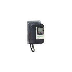
This Altivar Lift variable speed drive can feed 3-phase asynchronous and asynchronous motors (with or without encoder). It is designed with heatsink and it has a built-in EMC filter. It works at a rated supply voltage from 380V to 480V AC. This drive has been specially designed with and for professionals. It features advanced functions like half-floor control, inspection mode, rollback management, direct to floor, evacuation with UPS, load measurement, deferred thermal stop. It is suitable for motors with power rating up to 15 kW / 20 hp. Its dimensions are, 230mm wide, 400mm high, 187mm deep. This drive provides precision and durability for your lift applications. It complies with lift standards EN 12015 and EN 12016 without external filter. Accessories like remote graphic display terminal, simple loader tool and options like encoder interface cards, I/O cards are available with Altivar Lift drives.
Main
| Characteristic | Value(s) |
|---|---|
| Device short name | ATV71 |
| Product destination | Asynchronous motors Synchronous motors |
| Network number of phases | 3 phases |
| Supply voltage limits | 323â¦528 V |
| Supply frequency | 50...60 Hz - 5...5 % |
| Motor power kW | 15 kW, 3 phases at 380...480 V |
| Motor power hp | 20 hp, 3 phases at 380...480 V |
| Line current | 48 A for 380 V 3 phases 15 kW / 20 hp 39 A for 480 V 3 phases 15 kW / 20 hp |
| Range of product | Altivar Lift |
| Product or component type | Variable speed drive |
| Product specific application | Lift |
| Variant | With integrated 7-segment display terminal |
| Communication port protocol | Modbus CANopen |
| [Us] rated supply voltage | 380...480 V - 15...10 % |
| EMC filter | Integrated |
Complementary
| Characteristic | Value(s) |
|---|---|
| Apparent power | 31.6 kVA at 380 V 3 phases 15 kW / 20 hp |
| Prospective line Isc | 22 kA for 3 phases |
| Nominal output current | 33 A at 4 kHz 380 V 3 phases 15 kW / 20 hp 27 A at 4 kHz 460 V 3 phases 15 kW / 20 hp |
| Maximum transient current | 44.9 A for 2 s 3 phases / 15 kW / 20 hp |
| Speed drive output frequency | 0â¦599 Hz |
| Speed range | 1â¦100 for asynchronous motor in open-loop mode, without speed feedback 1â¦50 for synchronous motor in open-loop mode, without speed feedback 1â¦1000 for asynchronous motor in closed-loop mode with encoder feedback |
| Torque accuracy | +/- 5 % in closed-loop mode with encoder feedback +/- 15 % in open-loop mode, without speed feedback |
| Transient overtorque | 170 %, +/- 10 % for 60 s 220 %, +/- 10 % for 2 s |
| Braking torque | 30 % without braking resistor <= 150 % with braking or hoist resistor |
| Local signalling | 1 LED (red) for drive voltage |
| Output voltage | <= power supply voltage |
| Insulation | Electrical between power and control |
| type of cable for external connection | Without mounting kit: 1 wire(s)IEC cable at 45 °C, copper 90 °C / XLPE/EPR Without mounting kit: 1 wire(s)IEC cable at 45 °C, copper 70 °C / PVC With an IP21 or an IP31 kit: 3 wire(s)IEC cable at 40 °C, copper 70 °C / PVC With a NEMA Type1 kit: 3 wire(s)UL 508 cable at 40 °C, copper 75 °C / PVC |
| Electrical connection | Terminal, clamping capacity: 2.5 mm², AWG 14 (AI1-/AI1+, AI2, AO1, R1A, R1B, R1C, R2A, R2B, LI1...LI6, PWR) Terminal, clamping capacity: 35 mm², AWG 2 (L1/R, L2/S, L3/T, U/T1, V/T2, W/T3, PC/-, PO, PA/+, PA, PB) |
| Tightening torque | 5.4 N.m, 47.7 lb.in (L1/R, L2/S, L3/T, U/T1, V/T2, W/T3, PC/-, PO, PA/+, PA, PB) 0.6 N.m (AI1-/AI1+, AI2, AO1, R1A, R1B, R1C, R2A, R2B, LI1...LI6, PWR) |
| Supply | Internal supply for reference potentiometer (1 to 10 kOhm): 10.5 V DC +/- 5 %, <10 A, protection type: overload and short-circuit protection Internal supply: 24 V DC (21â¦27 V), <200 A, protection type: overload and short-circuit protection |
| Sampling duration | 2 ms +/- 0.5 ms (LI6)if configured as logic input - discrete input(s) 2 ms +/- 0.5 ms (LI1...LI5) - discrete input(s) 2 ms +/- 0.5 ms (AI1-/Al1+) - analog input(s) 2 ms +/- 0.5 ms (Al2) - analog input(s) |
| Response time | R1A, R1B, R1C 7 ms, tolerance +/- 0.5 ms for discrete output(s) R2A, R2B 7 ms, tolerance +/- 0.5 ms for discrete output(s) AO1 2 ms, tolerance +/- 0.5 ms for analog output(s) <= 100 ms in STO (Safe Torque Off) |
| Accuracy | +/- 0.6 % (AI1-/Al1+) for a temperature variation 60 °C +/- 0.6 % (AI2) for a temperature variation 60 °C +/- 1 % (AO1) for a temperature variation 60 °C |
| Linearity error | +/- 0.15 % of maximum value (AI1-/Al1+, AI2) +/- 0.2 % (AO1) |
| Analogue output type | AO1 software-configurable voltage: 0...10 V DC, impedance: 470 Ohm, resolution 10 bits AO1 software-configurable current: 0...20 mA, impedance: 500 Ohm, resolution 10 bits AO1 software-configurable logic output 10 V 20 A |
| Discrete output type | Configurable relay logic: (R1A, R1B, R1C) NO/NC - 100000 cycles Configurable relay logic: (R2A, R2B) NO - 100000 cycles |
| Minimum switching current | 3 mA at 24 V DC for configurable relay logic |
| Maximum switching current | 5 A at 250 V AC on resistive load - cos phi = 1 - L/R = 0 ms (R1, R2) 5 A at 30 V DC on resistive load - cos phi = 1 - L/R = 0 ms (R1, R2) 2 A at 250 V AC on inductive load - cos phi = 0.4 - L/R = 7 ms (R1, R2) 2 A at 30 V DC on inductive load - cos phi = 0.4 - L/R = 7 ms (R1, R2) |
| Discrete input type | Programmable (LI1...LI5)24 V DC, with level 1 PLC - 3500 Ohm Switch-configurable (LI6)24 V DC, with level 1 PLC - 3500 Ohm Switch-configurable PTC probe (LI6) - 0â¦6 probes - 1500 Ohm Safety input (PWR)24 V DC - 1500 Ohm |
| Discrete input logic | Positive logic (LI6)if configured as logic input, < 5 V (state 0), > 11 V (state 1) Negative logic (LI6)if configured as logic input, > 16 V (state 0), < 10 V (state 1) Positive logic (LI1...LI5), < 5 V (state 0), > 11 V (state 1) Negative logic (LI1...LI5), > 16 V (state 0), < 10 V (state 1) Positive logic (PWR), < 2 V (state 0), > 17 V (state 1) |
| Dielectric strength | 3535 V DC between earth and power terminals 5092 V DC between control and power terminals |
| Insulation resistance | > 1 mOhm 500 V DC for 1 minute to earth |
| Frequency resolution | Display unit: 0.1 Hz Analog input: 0.024/50 Hz |
| Connector type | 1 RJ45 (on front face) for Modbus 1 RJ45 (on terminal) for Modbus Male SUB-D 9 on RJ45 for CANopen |
| Physical interface | 2-wire RS 485 for Modbus |
| Transmission frame | RTU for Modbus |
| Transmission rate | 9600 bps, 19200 bps for Modbus on front face 4800 bps, 9600 bps, 19200 bps, 38.4 Kbps for Modbus on terminal 20 kbps, 50 kbps, 125 kbps, 250 kbps, 500 kbps, 1 Mbps for CANopen |
| Data format | 8 bits, 1 stop, even parity for Modbus on front face 8 bits, odd even or no configurable parity for Modbus on terminal |
| Type of polarization | No impedance for Modbus |
| Number of addresses | 1â¦247 for Modbus 1â¦127 for CANopen |
| control options | Communication card for Modbus TCP Communication card for Fipio Communication card for Modbus/Uni-Telway Communication card for Modbus Plus Communication card for EtherNet/IP Communication card for DeviceNet Communication card for Profibus DP Communication card for Profibus DP V1 Communication card for Interbus-S Communication card for CC-Link Interface card for encoder I/O extension card Controller inside programmable card Overhead crane card |
| Discrete input number | 7 |
| Discrete output number | 2 |
| Analogue input number | 2 |
| Analogue input type | AI2 software-configurable voltage: 0...10 V DC 24 V max, impedance: 30000 Ohm, resolution 11 bits AI1-/Al1+ bipolar differential voltage: +/- 10 V DC 24 V max, resolution 11 bits + sign AI2 software-configurable current: 0...20 mA, impedance: 242 Ohm, resolution 11 bits |
| Analogue output number | 1 |
| Method of access | Slave CANopen |
| Asynchronous motor control profile | Voltage/frequency ratio - Energy Saving, quadratic U/f Flux vector control without sensor, standard Flux vector control without sensor, ENA (energy Adaptation) system Voltage/frequency ratio, 5 points Flux vector control with sensor, standard Voltage/frequency ratio, 2 points Flux vector control without sensor, 2 points |
| Synchronous motor control profile | Vector control without sensor, standard Vector control with sensor, standard |
| Acceleration and deceleration ramps | S, U or customized Linear adjustable separately from 0.01 to 9000 s Automatic adaptation of ramp if braking capacity exceeded, by using resistor |
| Motor slip compensation | Automatic whatever the load Not available in voltage/frequency ratio (2 or 5 points) Suppressable Adjustable |
| Switching frequency | 1...16 kHz adjustable |
| Nominal switching frequency | 8 kHz |
| Minimum braking resistance | 7 Ohm |
| Network frequency | 47.5...63 Hz |
| Protection type | Overheating protection: drive Thermal protection: drive Short-circuit between motor phases: drive Input phase breaks: drive Overcurrent between output phases and earth: drive Overvoltages on the DC bus: drive Break on the control circuit: drive Against exceeding limit speed: drive Line supply undervoltage: drive Line supply overvoltage: drive Against input phase loss: drive Thermal protection: motor Motor phase break: motor Power removal: motor |
Main
| Characteristic | Value(s) |
|---|---|
| Range of Product | Altivar 61 |
| Product or Component Type | Variable speed drive |
| Product Specific Application | Pumping and ventilation machine |
| Component name | ATV61 |
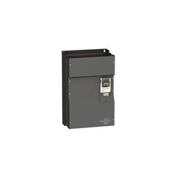
| Motor power kW | 400 kW, 3 phase 500 V 500 kW, 3 phase 690 V |
| Maximum Horse Power Rating | 550 hp, 3 phase 575 V |
| power supply voltage | 500...690 V - 15...10 % |
| supply number of phases | 3 phase |
| Line current | 494 A 600 V 3 phase 400 kW / 550 hp 505 A 690 V 3 phase 400 kW / 550 hp 547 A 500 V 3 phase 400 kW / 550 hp |
| EMC filter | Level 3 EMC filter |
| Assembly style | With heat sink |
| maximum prospective line Isc | 35 kA 3 phase |
| Maximum transient current | 708 A 60 s, 3 phase |
| Nominal switching frequency | 2.5 kHz |
| Switching frequency | 2.5...4.9 kHz adjustable 2.5...4.9 kHz with derating factor |
| asynchronous motor control | Voltage/frequency ratio, 5 points Flux vector control without sensor, standard Voltage/frequency ratio, 2 points Voltage/frequency ratio - Energy Saving, quadratic U/f |
| Synchronous motor control profile | Vector control without sensor, standard |
| Communication Port Protocol | CANopen Modbus |
| Type of polarization | No impedance Modbus |
| Option card | Communication card APOGEE FLN Communication card BACnet Communication card CC-Link Controller inside programmable card Communication card DeviceNet Communication card EtherNet/IP Communication card Fipio I/O extension card Communication card Interbus-S Communication card LonWorks Communication card METASYS N2 Communication card Modbus Plus Communication card Modbus TCP Communication card Modbus/Uni-Telway Multi-pump card Communication card Profibus DP Communication card Profibus DP V1 |
Complementary
| Characteristic | Value(s) |
|---|---|
| Product destination | Synchronous motors Asynchronous motors |
| power supply voltage limits | 425â¦759 V |
| power supply frequency | 50...60 Hz - 5...5 % |
| power supply frequency limits | 47.5...63 Hz |
| Continuous output current | 528 A 2.5 kHz, 575 V - 3 phase 543 A 2.5 kHz, 690 V - 3 phase 590 A 2.5 kHz, 500 V - 3 phase |
| Output frequency | 0.1â¦500 Hz |
| Speed range | 1â¦100 in open-loop mode, without speed feedback |
| Speed accuracy | +/- 10 % of nominal slip 0.2 Tn to Tn without speed feedback |
| Torque accuracy | +/- 15 % in open-loop mode, without speed feedback |
| Transient overtorque | 130 % of nominal motor torque +/- 10 % 60 s |
| Braking torque | <= 125 % with braking resistor 30 % without braking resistor |
| Regulation loop | Frequency PI regulator |
| Motor slip compensation | Adjustable Can be suppressed Not available in voltage/frequency ratio (2 or 5 points) Automatic whatever the load |
| diagnostic | 1 LED (red) for drive voltage |
| Output voltage | <= power supply voltage |
| electrical isolation | Between power and control terminals |
| type of cable for mounting in an enclosure | With an IP21 or an IP31 kit 3 IEC cable 104 °F (40 °C), copper 70 °C / PVC With UL Type 1 kit 3 UL 508 cable 104 °F (40 °C), copper 75 °C / PVC Without mounting kit 1 IEC cable 113 °F (45 °C), copper 70 °C / PVC Without mounting kit 1 IEC cable 113 °F (45 °C), copper 90 °C / XLPE/EPR |
| Electrical connection | Terminal 2.5 mm² / AWG 14 AI1-/AI1+, AI2, AO1, R1A, R1B, R1C, R2A, R2B, LI1...LI6, PWR) Terminal 8 x 185 mm² / 5 x 500 kcmil PC/-, PO, PA/+) Terminal 2 x 4 x 185 mm² / 2 x 3 x 500 kcmil R/L1.1, S/L2.1, T/L3.1, R/L1.2, S/L2.2, T/L3.2) Terminal 6 x 185 mm² / 5 x 500 kcmil U/T1, V/T2, W/T3) |
| Tightening torque | 5.3 lbf.in (0.6 N.m) AI1-/AI1+, AI2, AO1, R1A, R1B, R1C, R2A, R2B, LI1...LI6, PWR) 362.9 lbf.in (41 N.m), 360 lb.in PC/-, PO, PA/+) 362.9 lbf.in (41 N.m), 360 lb.in R/L1.1, S/L2.1, T/L3.1, R/L1.2, S/L2.2, T/L3.2) 362.9 lbf.in (41 N.m), 360 lb.in U/T1, V/T2, W/T3) |
| Supply | Internal supply for reference potentiometer (1 to 10 kOhm) 10.5 V DC, +/- 5 %, <10 mA overload and short-circuit protection Internal supply 24 V DC 21â¦27 V), <200 mA overload and short-circuit protection External supply 24 V DC 19â¦30 V) |
| Analogue input number | 2 |
| Analogue input type | AI1-/Al1+ bipolar differential voltage +/- 10 V DC 24 V max 11 bits + sign AI2 software-configurable current 0...20 mA 242 Ohm 11 bits AI2 software-configurable voltage 0...10 V DC 24 V max 30000 Ohm 11 bits |
| sampling time | 2 ms +/- 0.5 ms AI1-/Al1+) - analog input 2 ms +/- 0.5 ms Al2) - analog input 2 ms +/- 0.5 ms AO1) - analog output 2 ms +/- 0.5 ms LI1...LI5) - discrete input 2 ms +/- 0.5 ms LI6)if configured as logic input - discrete input |
| absolute accuracy precision | +/- 0.6 % AI1-/Al1+) for a temperature variation 60 °C +/- 0.6 % AI2) for a temperature variation 60 °C +/- 1 % AO1) for a temperature variation 60 °C |
| Linearity error | +/- 0.15 % of maximum value AI1-/Al1+) +/- 0.15 % of maximum value AI2) +/- 0.2 % AO1) |
| Analogue output number | 1 |
| Analogue output type | AO1 software-configurable current 0...20 mA 500 Ohm 10 bits AO1 software-configurable voltage 0...10 V DC 470 Ohm 10 bits AO1 software-configurable logic output 10 V, 20 mA |
| Discrete output number | 2 |
| Discrete output type | Configurable relay logic R1A, R1B, R1C) NO/NC - 100000 cycles Configurable relay logic R2A, R2B) NO - 100000 cycles |
| maximum response time | <= 100 ms in STO (Safe Torque Off) R1A, R1B, R1C <= 7 ms +/- 0.5 ms R2A, R2B <= 7 ms +/- 0.5 ms |
| Minimum switching current | 3 mA 24 V DC configurable relay logic |
| Maximum switching current | R1, R2 2 A 250 V AC inductive, cos phi = 0.4 7 ms R1, R2 2 A 30 V DC inductive, cos phi = 0.4 7 ms R1, R2 5 A 250 V AC resistive, cos phi = 1 0 ms R1, R2 5 A 30 V DC resistive, cos phi = 1 0 ms |
| Discrete input number | 7 |
| Discrete input type | Programmable LI1...LI5) 24 V DC <= 30 V)level 1 PLC - 3500 Ohm Switch-configurable LI6) 24 V DC <= 30 V)level 1 PLC - 3500 Ohm Switch-configurable PTC probe LI6)0â¦6 - 1500 Ohm Safety input PWR) 24 V DC <= 30 V) - 1500 Ohm |
| Discrete input logic | Negative logic (sink) LI1...LI5), > 16 V, < 10 V Positive logic (source) LI1...LI5), < 5 V, > 11 V Negative logic (sink) LI6)if configured as logic input, > 16 V, < 10 V Positive logic (source) LI6)if configured as logic input, < 5 V, > 11 V |
| Acceleration and deceleration ramps | S, U or customized Automatic adaptation of ramp if braking capacity exceeded, by using resistor Linear adjustable separately from 0.01 to 9000 s |
| Braking to standstill | By DC injection |
| Protection type | Against exceeding limit speed drive Against input phase loss drive Break on the control circuit drive Input phase breaks drive Line supply overvoltage drive Line supply undervoltage drive Overcurrent between output phases and earth drive Overheating protection drive Overvoltages on the DC bus drive Power removal drive Short-circuit between motor phases drive Thermal protection drive Motor phase break motor Power removal motor Thermal protection motor |
| Insulation resistance | > 1 mOhm 500 V DC for 1 minute to earth |
| Frequency resolution | Analog input 0.024/50 Hz Display unit 0.1 Hz |
| Connector type | 1 RJ45 on front face)Modbus 1 RJ45 on terminal)Modbus Male SUB-D 9 on RJ45CANopen |
| Physical interface | 2-wire RS 485 Modbus |
| Transmission frame | RTU Modbus |
| Transmission rate | 4800 bps, 9600 bps, 19200 bps, 38.4 Kbps Modbus on terminal 9600 bps, 19200 bps Modbus on front face 20 kbps, 50 kbps, 125 kbps, 250 kbps, 500 kbps, 1 Mbps CANopen |
| Data format | 8 bits, 1 stop, even parity Modbus on front face 8 bits, odd even or no configurable parity Modbus on terminal |
| Number of addresses | 1â¦127 CANopen 1â¦247 Modbus |
| Method of access | Slave CANopen |
| Marking | CE |
| Operating position | Vertical +/- 10 degree |
| Product Weight | 844.4 lb(US) (383 kg) |
| Width | 44.09 in (1120 mm) |
| Height | 54.7 in (1390 mm) |
| Depth | 14.8 in (377 mm) |

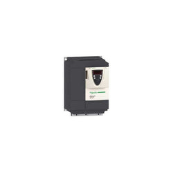
variable speed drive - ATV31 - 2.2kW - 380..500V - 3-phase supply - EMC filter - IP20
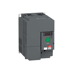
Variable speed drive ATV310 - 11 kW - 15 hp - 380...460 V - 3 phase
Main
| Characteristic | Value(s) |
|---|---|
| Range of Product | Altivar 71 |
| Product or Component Type | Variable speed drive |
| Product Specific Application | Complex, high-power machines |
| Component name | ATV71 |
| Motor power kW | 0.37 kW, 3 phase 200...240 V |
| Maximum Horse Power Rating | 0.5 hp, 3 phase 200...240 V |
| Maximum motor cable length | 164.04 ft (50 m) shielded cable 328.08 ft (100 m) unshielded cable |
| power supply voltage | 200...240 V - 15...10 % |
| Phase | 3 phase |
| Line current | 3.1 A 240 V 3 phase 0.37 kW / 0.5 hp 3.5 A 200 V 3 phase 0.37 kW / 0.5 hp |
| EMC filter | Integrated |
| Assembly style | With heat sink |
| Variant | Without remote graphic terminal |
| Apparent power | 1.3 kVA 240 V 3 phase 0.37 kW / 0.5 hp |
| Prospective line Isc | 5 kA 3 phase |
| Nominal output current | 3 A 4 kHz 230 V 3 phase 0.37 kW / 0.5 hp |
| Maximum transient current | 4.5 A 60 s 3 phase 0.37 kW / 0.5 hp 4.9 A 2 s 3 phase 0.37 kW / 0.5 hp |
| Output frequency | 0.1â¦599 Hz |
| Nominal switching frequency | 4 kHz |
| Switching frequency | 1...16 kHz adjustable 4...16 kHz with derating factor |
| Asynchronous motor control profile | Sensorless flux vector control (SFVC) (voltage or current vector) ENA (Energy adaptation) system for unbalanced loads Voltage/frequency ratio (2 or 5 points) Flux vector control (FVC) with sensor (current vector) |
| Type of polarization | No impedance Modbus |
Complementary
| Characteristic | Value(s) |
|---|---|
| Product destination | Synchronous motors Asynchronous motors |
| power supply voltage limits | 170â¦264 V |
| power supply frequency | 50...60 Hz - 5...5 % |
| power supply frequency limits | 47.5...63 Hz |
| Speed range | 1â¦100 asynchronous motor in open-loop mode, without speed feedback 1â¦1000 asynchronous motor in closed-loop mode with encoder feedback 1â¦50 synchronous motor in open-loop mode, without speed feedback |
| Speed accuracy | +/- 0.01 % of nominal speed in closed-loop mode with encoder feedback 0.2 Tn to Tn +/- 10 % of nominal slip without speed feedback 0.2 Tn to Tn |
| Torque accuracy | +/- 15 % in open-loop mode, without speed feedback +/- 5 % in closed-loop mode with encoder feedback |
| Transient overtorque | 170 % +/- 10 % 60 s every 10 minutes 220 % +/- 10 % 2 s |
| Braking torque | <= 150 % with braking or hoist resistor 30 % without braking resistor |
| Synchronous motor control profile | Vector control without speed feedback |
| Regulation loop | Adjustable PI regulator |
| Motor slip compensation | Adjustable Not available in voltage/frequency ratio (2 or 5 points) Suppressable Automatic whatever the load |
| diagnostic | 1 LED (red) for drive voltage |
| Output voltage | <= power supply voltage |
| Insulation | Electrical between power and control |
| type of cable for mounting in an enclosure | With a NEMA Type1 kit 3 UL 508 cable 104 °F (40 °C), copper 75 °C / PVC With an IP21 or an IP31 kit 3 IEC cable 104 °F (40 °C), copper 70 °C / PVC Without mounting kit 1 IEC cable 113 °F (45 °C), copper 70 °C / PVC Without mounting kit 1 IEC cable 113 °F (45 °C), copper 90 °C / XLPE/EPR |
| Electrical connection | Terminal 2.5 mm², AWG 14 AI1-/AI1+, AI2, AO1, R1A, R1B, R1C, R2A, R2B, LI1...LI6, PWR) Terminal 4 mm², AWG 10 L1/R, L2/S, L3/T, U/T1, V/T2, W/T3, PC/-, PO, PA/+, PA, PB) |
| Tightening torque | 5.3 lbf.in (0.6 N.m) AI1-/AI1+, AI2, AO1, R1A, R1B, R1C, R2A, R2B, LI1...LI6, PWR) 12.4 lbf.in (1.4 N.m), 12.3 lb.in L1/R, L2/S, L3/T, U/T1, V/T2, W/T3, PC/-, PO, PA/+, PA, PB) |
| Supply | Internal supply for reference potentiometer (1 to 10 kOhm) 10.5 V DC +/- 5 %, <10 mA overload and short-circuit protection Internal supply 24 V DC 21â¦27 V), <200 mA overload and short-circuit protection |
| Analogue input number | 2 |
| Analogue input type | AI1-/Al1+ bipolar differential voltage +/- 10 V DC 24 V max 11 bits + sign AI2 software-configurable current 0...20 mA 242 Ohm 11 bits AI2 software-configurable voltage 0...10 V DC 24 V max 30000 Ohm 11 bits |
| input sampling time | 2 ms +/- 0.5 ms AI1-/Al1+) - analog 2 ms +/- 0.5 ms Al2) - analog 2 ms +/- 0.5 ms LI1...LI5) - discrete 2 ms +/- 0.5 ms LI6)if configured as logic input - discrete |
| Response time | <= 100 ms in STO (Safe Torque Off) AO1 2 ms +/- 0.5 ms analog R1A, R1B, R1C 7 ms +/- 0.5 ms discrete R2A, R2B 7 ms +/- 0.5 ms discrete |
| absolute accuracy precision | +/- 0.6 % AI1-/Al1+) for a temperature variation 60 °C +/- 0.6 % AI2) for a temperature variation 60 °C +/- 1 % AO1) for a temperature variation 60 °C |
| Linearity error | +/- 0.15 % of maximum value AI1-/Al1+, AI2) +/- 0.2 % AO1) |
| Analogue output number | 1 |
| Analogue output type | AO1 software-configurable logic output 10 V 20 mA AO1 software-configurable current 0...20 mA 500 Ohm 10 bits AO1 software-configurable voltage 0...10 V DC 470 Ohm 10 bits |
| Discrete output number | 2 |
| Discrete output type | Configurable relay logic R1A, R1B, R1C) NO/NC - 100000 cycles Configurable relay logic R2A, R2B) NO - 100000 cycles |
| Minimum switching current | 3 mA 24 V DC configurable relay logic |
| Maximum switching current | R1, R2 2 A 250 V AC inductive, cos phi = 0.4 R1, R2 2 A 30 V DC inductive, cos phi = 0.4 R1, R2 5 A 250 V AC resistive, cos phi = 1 R1, R2 5 A 30 V DC resistive, cos phi = 1 |
| Discrete input number | 7 |
| Discrete input type | LI1...LI5 programmable 24 V DC level 1 PLC 3500 Ohm LI6 switch-configurable 24 V DC level 1 PLC 3500 Ohm LI6 switch-configurable PTC probe 0â¦6 1500 Ohm PWR safety input 24 V DC 1500 Ohm ISO 13849-1 level d |
| Discrete input logic | Negative logic (sink) LI1...LI5), > 16 V, < 10 V Positive logic (source) LI1...LI5), < 5 V, > 11 V Negative logic (sink) LI6)if configured as logic input, > 16 V, < 10 V Positive logic (source) LI6)if configured as logic input, < 5 V, > 11 V |
| Acceleration and deceleration ramps | Linear adjustable separately from 0.01 to 9000 s S, U or customized Automatic adaptation of ramp if braking capacity exceeded, by using resistor |
| Braking to standstill | By DC injection |
| Protection type | Against exceeding limit speed drive Against input phase loss drive Break on the control circuit drive Input phase breaks drive Line supply overvoltage drive Line supply undervoltage drive Overcurrent between output phases and earth drive Overheating protection drive Overvoltages on the DC bus drive Short-circuit between motor phases drive Thermal protection drive Motor phase break motor Power removal motor Thermal protection motor |
| Insulation resistance | > 1 mOhm 500 V DC for 1 minute to earth |
| Frequency resolution | Analog input 0.024/50 Hz Display unit 0.1 Hz |
| Communication Port Protocol | Modbus CANopen |
| Connector type | 1 RJ45 on front face)Modbus 1 RJ45 on terminal)Modbus Male SUB-D 9 on RJ45CANopen |
| Physical interface | 2-wire RS 485 Modbus |
| Transmission frame | RTU Modbus |
| Transmission rate | 4800 bps, 9600 bps, 19200 bps, 38.4 Kbps Modbus on terminal 9600 bps, 19200 bps Modbus on front face 20 kbps, 50 kbps, 125 kbps, 250 kbps, 500 kbps, 1 Mbps CANopen |
| Data format | 8 bits, 1 stop, even parity Modbus on front face 8 bits, odd even or no configurable parity Modbus on terminal |
| Number of addresses | 1â¦127 CANopen 1â¦247 Modbus |
| Method of access | Slave CANopen |
| Marking | CE |
| Operating position | Vertical +/- 10 degree |
| Height | 9.06 in (230 mm) |
| Depth | 6.9 in (175 mm) |
| Width | 5.1 in (130 mm) |
| Product Weight | 6.6 lb(US) (3 kg) |
| Option card | Communication card CC-Link Controller inside programmable card Communication card DeviceNet Communication card EtherNet/IP Communication card Fipio I/O extension card Communication card Interbus-S Interface card for encoder Communication card Modbus Plus Communication card Modbus TCP Communication card Modbus/Uni-Telway Overhead crane card Communication card Profibus DP Communication card Profibus DP V1 |

Main
| Characteristic | Value(s) |
|---|---|
| Range of Product | Lexium integrated drive |
| Product or Component Type | Motion integrated drive |
| Device short name | ILS |
| Motor Type | 3-phase stepper motor |
| Number of motor poles | 6 |
| Phase | Single phase |
| [Us] rated supply voltage | 24 V 48 V |
| Network type | DC |
| Communication interface | Modbus TCP, Integrated |
| Length | 6.7 in (170.6 mm) |
| Winding type | Medium speed of rotation and medium torque |
| Electrical Connection | Printed circuit board connector |
| Holding brake | Without |
| Gear box type | Without |
| Nominal speed | 180 rpm 24 V 360 rpm 48 V |
| Nominal torque | 35.4 lbf.in (4 N.m) |
| Holding torque | 35.4 lbf.in (4 N.m) |
Complementary
| Characteristic | Value(s) |
|---|---|
| Transmission Rate | 10, 100 Mbits |
| Mounting Support | Flange |
| Motor flange size | 3.3 in (85 mm) |
| Number of motor stacks | 2 |
| Centring collar diameter | 2.4 in (60 mm) |
| centring collar depth | 0.08 in (2 mm) |
| Number of mounting holes | 4 |
| Mounting holes diameter | 0.3 in (6.5 mm) |
| Circle diameter of the mounting holes | 3.9 in (99 mm) |
| Feedback type | Index pulse |
| Shaft end | Untapped |
| Second shaft | Without second shaft end |
| Shaft diameter | 0.5 in (12 mm) |
| Shaft length | 1.2 in (30 mm) |
| Supply voltage limits | 18â¦55 V |
| Current consumption | 5000 mA maximum continuous |
| Associated fuse rating | 16 A |
| Commissioning interface | RS485 Modbus TCP 9.6, 19.2 and 38.4 kbauds) |
| Input/output type | 4 signals (each be used as input or output) |
| Voltage state 0 guaranteed | -3...4.5 V |
| Voltage state 1 guaranteed | 15...30 V |
| Discrete input current | 10 mA at 24 V safety input 2 mA at 24 V 24 V signal interface |
| Discrete output voltage | 23...25 V |
| Maximum switching current | 100 mA per output 200 mA total |
| Protection Type | Overload of output voltage Safe torque off Short circuit of the output voltage |
| Peak stall torque | 35.4 lbf.in (4 N.m) |
| Continuous stall torque | 35.4 lbf.in (4 N.m) |
| Speed feedback resolution | 20000 points/turn |
| Accuracy error | +/- 6 arc min |
| Rotor inertia | 2.2 kg.cm² |
| Maximum mechanical speed | 3000 rpm |
| Maximum radial force Fr | 100 N |
| Maximum axial force Fa | 170 N tensile force) 30 N force pressure) |
| Service life in hours | 20000 h bearing |
| Marking | CE |
| type of cooling | Natural convection |
| Product Weight | 7.9 lb(US) (3.6 kg) |
Variable Speed Drive Altivar 61 - 4kW / 690V - IP20
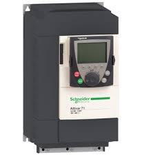
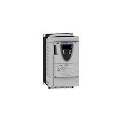
variable speed drive ATV71 - 5.5kW-7.5HP - 480V - EMC filter-graphic terminal
Main
| Characteristic | Value(s) |
|---|---|
| Range of Product | Altivar 71 |
| Product or Component Type | Variable speed drive |
| Product Specific Application | Complex, high-power machines |
| Component name | ATV71 |
| Motor power kW | 11 kW, 3 phase 200...240 V |
| Maximum Horse Power Rating | 15 hp, 3 phase 200...240 V |
| Maximum motor cable length | 164.04 ft (50 m) shielded cable 328.08 ft (100 m) unshielded cable |
| power supply voltage | 200...240 V - 15...10 % |
| Phase | 3 phase |
| Line current | 45.8 A 240 V 3 phase 11 kW / 15 hp 53.3 A 200 V 3 phase 11 kW / 15 hp |
| EMC filter | Without EMC filter |
| Assembly style | With heat sink |
| Variant | Without remote graphic terminal |
| Apparent power | 19 kVA 240 V 3 phase 11 kW / 15 hp |
| Prospective line Isc | 22 kA 3 phase |
| Nominal output current | 54 A 4 kHz 230 V 3 phase 11 kW / 15 hp |
| Maximum transient current | 81 A 60 s 3 phase 11 kW / 15 hp 89.1 A 2 s 3 phase 11 kW / 15 hp |
| Output frequency | 0.1â¦599 Hz |
| Nominal switching frequency | 4 kHz |
| Switching frequency | 1...16 kHz adjustable 4...16 kHz with derating factor |
| Asynchronous motor control profile | Voltage/frequency ratio (2 or 5 points) Sensorless flux vector control (SFVC) (voltage or current vector) ENA (Energy adaptation) system for unbalanced loads Flux vector control (FVC) with sensor (current vector) |
| Type of polarization | No impedance Modbus |
Complementary
| Characteristic | Value(s) |
|---|---|
| Product destination | Synchronous motors Asynchronous motors |
| power supply voltage limits | 170â¦264 V |
| power supply frequency | 50...60 Hz - 5...5 % |
| power supply frequency limits | 47.5...63 Hz |
| Speed range | 1â¦100 asynchronous motor in open-loop mode, without speed feedback 1â¦1000 asynchronous motor in closed-loop mode with encoder feedback 1â¦50 synchronous motor in open-loop mode, without speed feedback |
| Speed accuracy | +/- 0.01 % of nominal speed in closed-loop mode with encoder feedback 0.2 Tn to Tn +/- 10 % of nominal slip without speed feedback 0.2 Tn to Tn |
| Torque accuracy | +/- 15 % in open-loop mode, without speed feedback +/- 5 % in closed-loop mode with encoder feedback |
| Transient overtorque | 170 % +/- 10 % 60 s every 10 minutes 220 % +/- 10 % 2 s |
| Braking torque | <= 150 % with braking or hoist resistor 30 % without braking resistor |
| Synchronous motor control profile | Vector control without speed feedback |
| Regulation loop | Adjustable PI regulator |
| Motor slip compensation | Not available in voltage/frequency ratio (2 or 5 points) Suppressable Adjustable Automatic whatever the load |
| diagnostic | 1 LED (red) for drive voltage |
| Output voltage | <= power supply voltage |
| Insulation | Electrical between power and control |
| type of cable for mounting in an enclosure | With a NEMA Type1 kit 3 UL 508 cable 104 °F (40 °C), copper 75 °C / PVC With an IP21 or an IP31 kit 3 IEC cable 104 °F (40 °C), copper 70 °C / PVC Without mounting kit 1 IEC cable 113 °F (45 °C), copper 70 °C / PVC Without mounting kit 1 IEC cable 113 °F (45 °C), copper 90 °C / XLPE/EPR |
| Electrical connection | Terminal 2.5 mm², AWG 14 AI1-/AI1+, AI2, AO1, R1A, R1B, R1C, R2A, R2B, LI1...LI6, PWR) Terminal 35 mm², AWG 2 L1/R, L2/S, L3/T, U/T1, V/T2, W/T3, PC/-, PO, PA/+, PA, PB) |
| Tightening torque | 5.3 lbf.in (0.6 N.m) AI1-/AI1+, AI2, AO1, R1A, R1B, R1C, R2A, R2B, LI1...LI6, PWR) 47.8 lbf.in (5.4 N.m), 47.7 lb.in L1/R, L2/S, L3/T, U/T1, V/T2, W/T3, PC/-, PO, PA/+, PA, PB) |
| Supply | Internal supply for reference potentiometer (1 to 10 kOhm) 10.5 V DC +/- 5 %, <10 mA overload and short-circuit protection Internal supply 24 V DC 21â¦27 V), <200 mA overload and short-circuit protection |
| Analogue input number | 2 |
| Analogue input type | AI1-/Al1+ bipolar differential voltage +/- 10 V DC 24 V max 11 bits + sign AI2 software-configurable current 0...20 mA 242 Ohm 11 bits AI2 software-configurable voltage 0...10 V DC 24 V max 30000 Ohm 11 bits |
| input sampling time | 2 ms +/- 0.5 ms AI1-/Al1+) - analog 2 ms +/- 0.5 ms Al2) - analog 2 ms +/- 0.5 ms LI1...LI5) - discrete 2 ms +/- 0.5 ms LI6)if configured as logic input - discrete |
| Response time | <= 100 ms in STO (Safe Torque Off) AO1 2 ms +/- 0.5 ms analog R1A, R1B, R1C 7 ms +/- 0.5 ms discrete R2A, R2B 7 ms +/- 0.5 ms discrete |
| absolute accuracy precision | +/- 0.6 % AI1-/Al1+) for a temperature variation 60 °C +/- 0.6 % AI2) for a temperature variation 60 °C +/- 1 % AO1) for a temperature variation 60 °C |
| Linearity error | +/- 0.15 % of maximum value AI1-/Al1+, AI2) +/- 0.2 % AO1) |
| Analogue output number | 1 |
| Analogue output type | AO1 software-configurable logic output 10 V 20 mA AO1 software-configurable current 0...20 mA 500 Ohm 10 bits AO1 software-configurable voltage 0...10 V DC 470 Ohm 10 bits |
| Discrete output number | 2 |
| Discrete output type | Configurable relay logic R1A, R1B, R1C) NO/NC - 100000 cycles Configurable relay logic R2A, R2B) NO - 100000 cycles |
| Minimum switching current | 3 mA 24 V DC configurable relay logic |
| Maximum switching current | R1, R2 2 A 250 V AC inductive, cos phi = 0.4 R1, R2 2 A 30 V DC inductive, cos phi = 0.4 R1, R2 5 A 250 V AC resistive, cos phi = 1 R1, R2 5 A 30 V DC resistive, cos phi = 1 |
| Discrete input number | 7 |
| Discrete input type | LI1...LI5 programmable 24 V DC level 1 PLC 3500 Ohm LI6 switch-configurable 24 V DC level 1 PLC 3500 Ohm LI6 switch-configurable PTC probe 0â¦6 1500 Ohm PWR safety input 24 V DC 1500 Ohm ISO 13849-1 level d |
| Discrete input logic | Negative logic (sink) LI1...LI5), > 16 V, < 10 V Positive logic (source) LI1...LI5), < 5 V, > 11 V Negative logic (sink) LI6)if configured as logic input, > 16 V, < 10 V Positive logic (source) LI6)if configured as logic input, < 5 V, > 11 V |
| Acceleration and deceleration ramps | S, U or customized Automatic adaptation of ramp if braking capacity exceeded, by using resistor Linear adjustable separately from 0.01 to 9000 s |
| Braking to standstill | By DC injection |
| Protection type | Against exceeding limit speed drive Against input phase loss drive Break on the control circuit drive Input phase breaks drive Line supply overvoltage drive Line supply undervoltage drive Overcurrent between output phases and earth drive Overheating protection drive Overvoltages on the DC bus drive Short-circuit between motor phases drive Thermal protection drive Motor phase break motor Power removal motor Thermal protection motor |
| Insulation resistance | > 1 mOhm 500 V DC for 1 minute to earth |
| Frequency resolution | Analog input 0.024/50 Hz Display unit 0.1 Hz |
| Communication Port Protocol | Modbus CANopen |
| Connector type | 1 RJ45 on front face)Modbus 1 RJ45 on terminal)Modbus Male SUB-D 9 on RJ45CANopen |
| Physical interface | 2-wire RS 485 Modbus |
| Transmission frame | RTU Modbus |
| Transmission rate | 4800 bps, 9600 bps, 19200 bps, 38.4 Kbps Modbus on terminal 9600 bps, 19200 bps Modbus on front face 20 kbps, 50 kbps, 125 kbps, 250 kbps, 500 kbps, 1 Mbps CANopen |
| Data format | 8 bits, 1 stop, even parity Modbus on front face 8 bits, odd even or no configurable parity Modbus on terminal |
| Number of addresses | 1â¦127 CANopen 1â¦247 Modbus |
| Method of access | Slave CANopen |
| Marking | CE |
| Operating position | Vertical +/- 10 degree |
| Height | 15.7 in (400 mm) |
| Depth | 8.4 in (213 mm) |
| Width | 9.06 in (230 mm) |
| Product Weight | 48.5 lb(US) (22 kg) |
| Option card | Communication card CC-Link Controller inside programmable card Communication card DeviceNet Communication card EtherNet/IP Communication card Fipio I/O extension card Communication card Interbus-S Interface card for encoder Communication card Modbus Plus Communication card Modbus TCP Communication card Modbus/Uni-Telway Overhead crane card Communication card Profibus DP Communication card Profibus DP V1 |
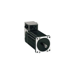
Main
| Characteristic | Value(s) |
|---|---|
| Range of Product | Lexium integrated drive |
| Product or Component Type | Motion integrated drive |
| Device short name | ILS |
| Motor Type | 3-phase stepper motor |
| Number of motor poles | 6 |
| Phase | Single phase |
| [Us] rated supply voltage | 24 V 48 V |
| Network type | DC |
| Communication interface | EtherCAT, Integrated |
| Length | 9.7 in (247.3 mm) |
| Winding type | High speed of rotation and medium torque |
| Electrical Connection | Printed circuit board connector |
| Holding brake | With |
| Gear box type | Without |
| Nominal speed | 200 rpm 24 V 400 rpm 48 V |
| Nominal torque | 39.8 lbf.in (4.5 N.m) |
| Holding torque | 53.1 lbf.in (6 N.m) holding brake 39.8 lbf.in (4.5 N.m) |
Complementary
| Characteristic | Value(s) |
|---|---|
| Transmission Rate | 100 Mbits |
| Mounting Support | Flange |
| Motor flange size | 3.3 in (85 mm) |
| Number of motor stacks | 3 |
| Centring collar diameter | 2.4 in (60 mm) |
| centring collar depth | 0.08 in (2 mm) |
| Number of mounting holes | 4 |
| Mounting holes diameter | 0.3 in (6.5 mm) |
| Circle diameter of the mounting holes | 3.9 in (99 mm) |
| Feedback type | Index pulse |
| Shaft end | Untapped |
| Second shaft | Without second shaft end |
| Shaft diameter | 0.6 in (14 mm) |
| Shaft length | 1.2 in (30 mm) |
| Supply voltage limits | 18â¦55 V |
| Current consumption | 6000 mA maximum continuous |
| Associated fuse rating | 16 A |
| Commissioning interface | RS485 Modbus TCP 9.6, 19.2 and 38.4 kbauds) |
| Input/output type | 4 signals (each be used as input or output) |
| Voltage state 0 guaranteed | -3...4.5 V |
| Voltage state 1 guaranteed | 15...30 V |
| Discrete input current | 10 mA at 24 V safety input 2 mA at 24 V 24 V signal interface |
| Discrete output voltage | 23...25 V |
| Maximum switching current | 100 mA per output 200 mA total |
| Protection Type | Overload of output voltage Short circuit of the output voltage Safe torque off |
| Peak stall torque | 39.8 lbf.in (4.5 N.m) |
| Continuous stall torque | 39.8 lbf.in (4.5 N.m) |
| Speed feedback resolution | 20000 points/turn |
| Accuracy error | +/- 6 arc min |
| Rotor inertia | 3.5 kg.cm² |
| Maximum mechanical speed | 3000 rpm |
| Maximum radial force Fr | 110 N |
| Maximum axial force Fa | 170 N tensile force) 30 N force pressure) |
| Service life in hours | 20000 h bearing |
| Brake pull-in power | 22 W |
| Brake release time | 40 ms |
| Brake application time | 20 ms |
| Marking | CE |
| type of cooling | Natural convection |
| Product Weight | 14.3 lb(US) (6.5 kg) |
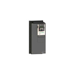
Variable Speed Drive Altivar 71 - 22kW-30hp - 480V - with EMC filter and Graphic Terminal

Main
| Characteristic | Value(s) |
|---|---|
| Range of Product | Altivar |
| Product or Component Type | Variable speed drive |
| Product Specific Application | Simple machine |
| Component name | ATV31 |
| Assembly style | With heat sink |
| Variant | With drive order potentiometer |
| EMC filter | Integrated |
| [Us] rated supply voltage | 380...500 V - 5...5 % |
| Supply frequency | 50...60 Hz - 5...5 % |
| Phase | 3 phase |
| Motor power kW | 3 kW 4 kHz |
| Line current | 10.9 A 380 V, Isc = 1 kA 8.3 A 500 V |
| Apparent power | 7.1 kVA |
| Prospective line Isc | 1 kA |
| Nominal output current | 7.1 A 4 kHz |
| Maximum transient current | 10.7 A 60 s |
| Power dissipation in W | 125 W at nominal load |
| Asynchronous motor control profile | Factory set : constant torque Sensorless flux vector control with PWM type motor control signal |
| Analogue input number | 4 |
Complementary
| Characteristic | Value(s) |
|---|---|
| Product destination | Asynchronous motors |
| Supply voltage limits | 323â¦550 V |
| Network Frequency | 47.5...63 Hz |
| Output frequency | 0.0005â¦0.5 kHz |
| Nominal switching frequency | 4 kHz |
| Switching frequency | 2...16 kHz adjustable |
| Speed range | 1â¦50 |
| Transient overtorque | 150â¦170 % of nominal motor torque |
| Braking torque | <= 150 % 60 s with braking resistor 100 % with braking resistor continuously 150 % without braking resistor |
| Regulation loop | Frequency PI regulator |
| Motor slip compensation | Automatic whatever the load Adjustable Suppressable |
| Output voltage | <= power supply voltage |
| Electrical connection | Al1, Al2, Al3, AOV, AOC, R1A, R1B, R1C, R2A, R2B, LI1...LI6 terminal 0.004 in² (2.5 mm²) AWG 14 L1, L2, L3, U, V, W, PA, PB, PA/+, PC/- terminal 0.004 in² (2.5 mm²) AWG 14 |
| Tightening torque | Al1, Al2, Al3, AOV, AOC, R1A, R1B, R1C, R2A, R2B, LI1...LI6 5.3 lbf.in (0.6 N.m) L1, L2, L3, U, V, W, PA, PB, PA/+, PC/- 7.08 lbf.in (0.8 N.m) |
| Insulation | Electrical between power and control |
| Supply | Internal supply for logic inputs 19...30 V 100 mA overload and short-circuit protection Internal supply for reference potentiometer (2.2 to 10 kOhm) 10...10.8 V 10 mA overload and short-circuit protection |
| Analogue input type | AI3 configurable current 0...20 mA 250 Ohm AI1 configurable voltage 0...10 V 30 V max 30000 Ohm AI2 configurable voltage +/- 10 V 30 V max 30000 Ohm AIP potentiometer reference 8 ms 10 bits +/- 4.3 % +/- 0.2 % |
| Sampling duration | LI1...LI6 4 ms discrete AI1, AI2, AI3 8 ms analog |
| Response time | AOV, AOC 8 ms analog R1A, R1B, R1C, R2A, R2B 8 ms discrete |
| Linearity error | +/- 0.2 % output |
| Analogue output number | 2 |
| Analogue output type | AOC configurable current 0...20 mA 800 Ohm 8 bits AOV configurable voltage 0...10 V 470 Ohm 8 bits |
| Discrete input logic | Positive logic (source) LI1...LI6), < 5 V, > 11 V Logic input not wired LI1...LI4), < 13 V Negative logic (source) LI1...LI6), > 19 V |
| Discrete output number | 2 |
| Discrete output type | Configurable relay logic R1A, R1B, R1C) 1 NO + 1 NC - 100000 cycles Configurable relay logic R2A, R2B) NC - 100000 cycles |
| Minimum switching current | R1-R2 10 mA 5 V DC |
| Maximum switching current | R1-R2 2 A 250 V AC inductive, cos phi = 0.4 7 ms R1-R2 2 A 30 V DC inductive, cos phi = 0.4 7 ms R1-R2 5 A 250 V AC resistive, cos phi = 1 0 ms R1-R2 5 A 30 V DC resistive, cos phi = 1 0 ms |
| Discrete input number | 6 |
| Discrete input type | LI1...LI6) programmable 24 V, 0â¦100 mA PLC 3500 Ohm |
| Acceleration and deceleration ramps | Linear adjustable separately from 0.1 to 999.9 s S, U or customized |
| Braking to standstill | By DC injection |
| Protection type | Input phase breaks drive Line supply overvoltage and undervoltage safety circuits drive Line supply phase loss safety function, for three phases supply drive Motor phase breaks drive Overcurrent between output phases and earth (on power up only) drive Overheating protection drive Short-circuit between motor phases drive Thermal protection motor |
| Insulation resistance | >= 500 mOhm 500 V DC for 1 minute |
| Display type | 1 LED Red)drive voltage Four 7-segment display unitsCANopen bus status |
| Time constant | 5 ms for reference change |
| Frequency resolution | Display unit 0.1 Hz Analog input 0.1...100 Hz |
| Connector type | 1 RJ45 CANopen via VW3 CANTAP2 adaptor 1 RJ45 Modbus |
| Physical interface | RS485 multidrop serial link CANopen via VW3 CANTAP2 adaptor RS485 multidrop serial link Modbus |
| Transmission frame | RTU CANopen via VW3 CANTAP2 adaptor RTU Modbus |
| Transmission Rate | 10, 20, 50, 125, 250, 500 kbps or 1 Mbps CANopen via VW3 CANTAP2 adaptor 4800, 9600 or 19200 bps Modbus |
| Number of addresses | 1â¦127 CANopen via VW3 CANTAP2 adaptor 1â¦247 Modbus |
| Number of drive | 127 CANopen via VW3 CANTAP2 adaptor 31 Modbus |
| Marking | CE |
| Operating position | Vertical +/- 10 degree |
| Product Weight | 6.8 lb(US) (3.1 kg) |
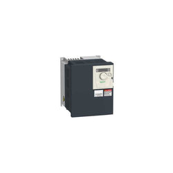
Main
| Characteristic | Value(s) |
|---|---|
| Range of Product | Altivar 312 |
| Product or Component Type | Variable speed drive |
| Product destination | Asynchronous motors |
| Product Specific Application | Simple machine |
| Assembly style | With heat sink |
| Component name | ATV312 |
| Motor power kW | 2.2 kW |
| Maximum Horse Power Rating | 3 hp |
| [Us] rated supply voltage | 380...500 V - 15...10 % |
| Supply frequency | 50...60 Hz - 5...5 % |
| Phase | 3 phase |
| Line current | 8.9 A 380 V, Isc = 5 kA 6.7 A 500 V |
| EMC filter | Integrated |
| Apparent power | 5.9 kVA |
| Maximum transient current | 8.3 A 60 s |
| Power dissipation in W | 79 W at nominal load |
| Speed range | 1â¦50 |
| Asynchronous motor control profile | Sensorless flux vector control with PWM type motor control signal Factory set : constant torque |
| Electrical connection | L1, L2, L3, U, V, W, PA, PB, PA/+, PC/- terminal 0.008 in² (5 mm²) AWG 10 |
| Supply | Internal supply for logic inputs 19...30 V 100 mA overload and short-circuit protection Internal supply for reference potentiometer (2.2 to 10 kOhm) 10...10.8 V 10 mA overload and short-circuit protection |
| Communication Port Protocol | CANopen Modbus |
| IP degree of protection | IP20 on upper part without cover plate IP21 on connection terminals IP31 on upper part IP41 on upper part |
| Option card | Communication card CANopen daisy chain Communication card DeviceNet Communication card Fipio Communication card Modbus TCP Communication card Profibus DP |
Complementary
| Characteristic | Value(s) |
|---|---|
| Supply voltage limits | 323â¦550 V |
| Prospective line Isc | 5 kA |
| Continuous output current | 5.5 A 4 kHz |
| Output frequency | 0â¦500 Hz |
| Nominal switching frequency | 4 kHz |
| Switching frequency | 2...16 kHz adjustable |
| Transient overtorque | 170â¦200 % of nominal motor torque |
| Braking torque | 150 % 60 s with braking resistor 100 % with braking resistor continuously 150 % without braking resistor |
| Regulation loop | Frequency PI regulator |
| Motor slip compensation | Suppressable Adjustable Automatic whatever the load |
| Output voltage | <= power supply voltage |
| Tightening torque | L1, L2, L3, U, V, W, PA, PB, PA/+, PC/- 10.6 lbf.in (1.2 N.m) |
| Insulation | Electrical between power and control |
| Acceleration and deceleration ramps | Linear adjustable separately from 0.1 to 999.9 s S, U or customized |
| Braking to standstill | By DC injection |
| Protection type | Input phase breaks drive Line supply overvoltage and undervoltage safety circuits drive Line supply phase loss safety function, for three phases supply drive Motor phase breaks drive Overcurrent between output phases and earth (on power up only) drive Overheating protection drive Short-circuit between motor phases drive Thermal protection motor |
| Insulation resistance | >= 500 mOhm 500 V DC for 1 minute |
| Local signalling | 1 LED (red) for drive voltage Four 7-segment display units for CANopen bus status |
| Time constant | 5 ms for reference change |
| Frequency resolution | Analog input 0.1...100 Hz Display unit 0.1 Hz |
| Connector type | 1 RJ45 Modbus/CANopen |
| Physical interface | RS485 multidrop serial link |
| Transmission frame | RTU |
| Transmission Rate | 10, 20, 50, 125, 250, 500 kbps or 1 Mbps CANopen 4800, 9600 or 19200 bps Modbus |
| Number of addresses | 1â¦127 CANopen 1â¦247 Modbus |
| Number of drive | 127 CANopen 31 Modbus |
| Marking | CE |
| Operating position | Vertical +/- 10 degree |
| Outer dimension | 215 x 185 x 158 mm 184 x 140 x 150 mm 402 x 239 x 192 mm |
| Height | 7.2 in (184 mm) |
| Width | 5.6 in (142 mm) |
| Depth | 6.0 in (152 mm) |
| Product Weight | 6.8 lb(US) (3.1 kg) |
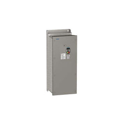
Main
| Characteristic | Value(s) |
|---|---|
| Range of Product | Altivar 21 |
| Product or Component Type | Variable speed drive |
| Product destination | Asynchronous motors |
| Product Specific Application | Pumps and fans in HVAC |
| Assembly style | With heat sink |
| Component name | ATV21 |
| EMC filter | Class A EMC filter integrated |
| power supply voltage | 380...480 V - 15...10 % |
| Phase | 3 phase |
| Motor power kW | 18.5 kW |
| Maximum Horse Power Rating | 25 hp |
| Line current | 27.8 A 480 V 34.9 A 380 V |
| Speed range | 1â¦10 |
| Transient overtorque | 120 % of nominal motor torque +/- 10 % 60 s |
| Asynchronous motor control profile | Constant voltage/frequency ratio Current flux vector control (FVC) without speed feedback Energy saving ratio Constant voltage/frequency ratio with automatic IR compensation Quadratic voltage/frequency ratio |
| Communication Port Protocol | Modbus |
| Type of polarization | No impedance |
| IP degree of protection | IP54 EN 60530 IP54 EN 61800-5-2 IP54 IEC 60529 IP54 IEC 61800-5-1 |
| Option card | Communication card APOGEE FLN Communication card BACnet Communication card LonWorks Communication card METASYS N2 |
Complementary
| Characteristic | Value(s) |
|---|---|
| power supply voltage limits | 323â¦528 V |
| power supply frequency | 50...60 Hz - 5...5 % |
| power supply frequency limits | 47.5â¦63 Hz |
| Apparent power | 28.2 kVA 380 V |
| maximum prospective line Isc | 22 kA |
| maximum continuous output current | 37 A 380 V 37 A 460 V |
| Maximum transient current | 40.7 A 60 s |
| Speed drive output frequency | 0.5â¦200 Hz |
| Nominal switching frequency | 8 kHz |
| Switching frequency | 6...16 kHz adjustable 8...16 kHz with derating factor |
| Speed accuracy | +/- 10 % of nominal slip 0.2 Tn to Tn |
| Torque accuracy | +/- 15 % |
| Regulation loop | Adjustable PI regulator |
| Motor slip compensation | Not available in voltage/frequency ratio motor control Automatic whatever the load Adjustable |
| diagnostic | 1 LED (red) for DC bus energized |
| Output voltage | <= power supply voltage |
| Insulation | Electrical between power and control |
| recommended type of cable for mounting in an enclosure | With UL Type 1 kit 3 UL 508 cable 104 °F (40 °C), copper 75 °C / PVC Without mounting kit 1 IEC cable 113 °F (45 °C), copper 70 °C / PVC Without mounting kit 1 IEC cable 113 °F (45 °C), copper 90 °C / XLPE/EPR |
| Electrical connection | VIA, VIB, FM, FLA, FLB, FLC, RY, RC, F, R, RES terminal 0.004 in² (2.5 mm²) / AWG 14 L1/R, L2/S, L3/T terminal 0.04 in² (25 mm²) / AWG 3 |
| Tightening torque | 5.3 lbf.in (0.6 N.m) VIA, VIB, FM, FLA, FLB, FLC, RY, RC, F, R, RES) 47.8 lbf.in (5.4 N.m), 48 lb.in L1/R, L2/S, L3/T) |
| Supply | Internal supply 24 V DC 21â¦27 V), <200 mA overload and short-circuit protection Internal supply for reference potentiometer (1 to 10 kOhm) 10.5 V DC +/- 5 %, <10 mA overload and short-circuit protection |
| Analogue input number | 2 |
| Analogue input type | VIA switch-configurable current 0...20 mA 242 Ohm 11 bits VIA switch-configurable voltage 0...10 V DC 24 V max 30000 Ohm 11 bits VIB configurable PTC probe 0...6 probes 1500 Ohm VIB configurable voltage 0...10 V DC 24 V max 30000 Ohm 11 bits |
| Sampling duration | F 2 ms +/- 0.5 ms discrete R 2 ms +/- 0.5 ms discrete RES 2 ms +/- 0.5 ms discrete VIA 2 ms +/- 0.5 ms analog VIB 2 ms +/- 0.5 ms analog |
| Response time | FLA, FLC 7 ms +/- 0.5 ms discrete FLB, FLC 7 ms +/- 0.5 ms discrete FM 2 ms +/- 0.5 ms analog RY, RC 7 ms +/- 0.5 ms discrete |
| Accuracy | +/- 1 % FM) for a temperature variation 60 °C +/- 0.6 % VIA) for a temperature variation 60 °C +/- 0.6 % VIB) for a temperature variation 60 °C |
| Linearity error | FM +/- 0.2 % output VIA +/- 0.15 % of maximum value input VIB +/- 0.15 % of maximum value input |
| Analogue output number | 1 |
| Analogue output type | FM switch-configurable current 0...20 mA 500 Ohm 10 bits FM switch-configurable voltage 0...10 V DC 470 Ohm 10 bits |
| Discrete output number | 2 |
| Discrete output type | Configurable relay logic FLA, FLC) NO - 100000 cycles Configurable relay logic FLB, FLC) NC - 100000 cycles Configurable relay logic RY, RC) NO - 100000 cycles |
| Minimum switching current | 3 mA 24 V DC configurable relay logic |
| Maximum switching current | 2 A 250 V AC inductive cos phi = 0.4 L/R = 7 ms FL, R) 2 A 30 V DC inductive cos phi = 0.4 L/R = 7 ms FL, R) 5 A 250 V AC resistive cos phi = 1 L/R = 0 ms FL, R) 5 A 30 V DC resistive cos phi = 1 L/R = 0 ms FL, R) |
| Discrete input type | F programmable 24 V DC level 1 PLC 3500 Ohm R programmable 24 V DC level 1 PLC 3500 Ohm RES programmable 24 V DC level 1 PLC 3500 Ohm |
| Discrete input logic | Negative logic (sink) F, R, RES), >= 16 V, <= 10 V Positive logic (source) F, R, RES), <= 5 V, >= 11 V |
| Acceleration and deceleration ramps | Automatic based on the load Linear adjustable separately from 0.01 to 3200 s |
| Braking to standstill | By DC injection |
| Protection type | Against input phase loss drive Break on the control circuit drive Input phase breaks drive Line supply overvoltage and undervoltage drive Line supply undervoltage drive Overcurrent between output phases and earth drive Overheating protection drive Overvoltages on the DC bus drive Short-circuit between motor phases drive Thermal power stage drive Motor phase break motor Thermal protection motor With PTC probes motor Against exceeding limit speed drive |
| Insulation resistance | >= 1 mOhm 500 V DC for 1 minute |
| Frequency resolution | Analog input 0.024/50 Hz Display unit 0.1 Hz |
| Connector Type | 1 RJ45 |
| Physical interface | 2-wire RS 485 |
| Transmission frame | RTU |
| Transmission Rate | 9600 bps or 19200 bps |
| Data format | 8 bits, 1 stop, odd even or no configurable parity |
| Number of addresses | 1â¦247 |
| Communication Service | Write single register (06) Monitoring inhibitable Write multiple registers (16) 2 words maximum Read device identification (43) Read holding registers (03) 2 words maximum Time out setting from 0.1 to 100 s |
| Marking | CE |
| Operating position | Vertical +/- 10 degree |
| Height | 26.2 in (665 mm) |
| Width | 12.2 in (310 mm) |
| Depth | 12.4 in (315 mm) |
| Product Weight | 82.5 lb(US) (37.4 kg) |
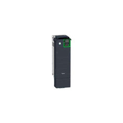
Variable Speed Drive ATV630 - 37kW/50hp - 200...240V - IP21/UL type 1
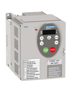
Main
| Characteristic | Value(s) |
|---|---|
| Range of Product | Altivar 21 |
| Product or Component Type | Variable speed drive |
| Product destination | Asynchronous motors |
| Product Specific Application | Pumps and fans in HVAC |
| Assembly style | With heat sink |
| Component name | ATV21 |
| EMC filter | Class A EMC filter integrated |
| power supply voltage | 380...480 V - 15...10 % |
| Phase | 3 phase |
| Motor power kW | 7.5 kW |
| Maximum Horse Power Rating | 10 hp |
| Line current | 11.7 A 480 V 14.7 A 380 V |
| Speed range | 1â¦10 |
| Transient overtorque | 120 % of nominal motor torque +/- 10 % 60 s |
| Asynchronous motor control profile | Quadratic voltage/frequency ratio Energy saving ratio Constant voltage/frequency ratio Constant voltage/frequency ratio with automatic IR compensation Current flux vector control (FVC) without speed feedback |
| Communication Port Protocol | Modbus |
| Type of polarization | No impedance |
| IP degree of protection | IP54 EN 60530 IP54 EN 61800-5-2 IP54 IEC 60529 IP54 IEC 61800-5-1 |
| Option card | Communication card APOGEE FLN Communication card BACnet Communication card LonWorks Communication card METASYS N2 |
Complementary
| Characteristic | Value(s) |
|---|---|
| power supply voltage limits | 323â¦528 V |
| power supply frequency | 50...60 Hz - 5...5 % |
| power supply frequency limits | 47.5â¦63 Hz |
| Apparent power | 12.2 kVA 380 V |
| maximum prospective line Isc | 22 kA |
| maximum continuous output current | 16 A 380 V 16 A 460 V |
| Maximum transient current | 17.6 A 60 s |
| Speed drive output frequency | 0.5â¦200 Hz |
| Nominal switching frequency | 12 kHz |
| Switching frequency | 12...16 kHz with derating factor 6...16 kHz adjustable |
| Speed accuracy | +/- 10 % of nominal slip 0.2 Tn to Tn |
| Torque accuracy | +/- 15 % |
| Regulation loop | Adjustable PI regulator |
| Motor slip compensation | Automatic whatever the load Not available in voltage/frequency ratio motor control Adjustable |
| diagnostic | 1 LED (red) for DC bus energized |
| Output voltage | <= power supply voltage |
| Insulation | Electrical between power and control |
| recommended type of cable for mounting in an enclosure | With UL Type 1 kit 3 UL 508 cable 104 °F (40 °C), copper 75 °C / PVC Without mounting kit 1 IEC cable 113 °F (45 °C), copper 70 °C / PVC Without mounting kit 1 IEC cable 113 °F (45 °C), copper 90 °C / XLPE/EPR |
| Electrical connection | VIA, VIB, FM, FLA, FLB, FLC, RY, RC, F, R, RES terminal 0.004 in² (2.5 mm²) / AWG 14 L1/R, L2/S, L3/T terminal 0.02 in² (16 mm²) / AWG 6 |
| Tightening torque | 5.3 lbf.in (0.6 N.m) VIA, VIB, FM, FLA, FLB, FLC, RY, RC, F, R, RES) 22.1 lbf.in (2.5 N.m), 22 lb.in L1/R, L2/S, L3/T) |
| Supply | Internal supply 24 V DC 21â¦27 V), <200 mA overload and short-circuit protection Internal supply for reference potentiometer (1 to 10 kOhm) 10.5 V DC +/- 5 %, <10 mA overload and short-circuit protection |
| Analogue input number | 2 |
| Analogue input type | VIA switch-configurable current 0...20 mA 242 Ohm 11 bits VIA switch-configurable voltage 0...10 V DC 24 V max 30000 Ohm 11 bits VIB configurable PTC probe 0...6 probes 1500 Ohm VIB configurable voltage 0...10 V DC 24 V max 30000 Ohm 11 bits |
| Sampling duration | F 2 ms +/- 0.5 ms discrete R 2 ms +/- 0.5 ms discrete RES 2 ms +/- 0.5 ms discrete VIA 2 ms +/- 0.5 ms analog VIB 2 ms +/- 0.5 ms analog |
| Response time | FLA, FLC 7 ms +/- 0.5 ms discrete FLB, FLC 7 ms +/- 0.5 ms discrete FM 2 ms +/- 0.5 ms analog RY, RC 7 ms +/- 0.5 ms discrete |
| Accuracy | +/- 1 % FM) for a temperature variation 60 °C +/- 0.6 % VIA) for a temperature variation 60 °C +/- 0.6 % VIB) for a temperature variation 60 °C |
| Linearity error | FM +/- 0.2 % output VIA +/- 0.15 % of maximum value input VIB +/- 0.15 % of maximum value input |
| Analogue output number | 1 |
| Analogue output type | FM switch-configurable current 0...20 mA 500 Ohm 10 bits FM switch-configurable voltage 0...10 V DC 470 Ohm 10 bits |
| Discrete output number | 2 |
| Discrete output type | Configurable relay logic FLA, FLC) NO - 100000 cycles Configurable relay logic FLB, FLC) NC - 100000 cycles Configurable relay logic RY, RC) NO - 100000 cycles |
| Minimum switching current | 3 mA 24 V DC configurable relay logic |
| Maximum switching current | 2 A 250 V AC inductive cos phi = 0.4 L/R = 7 ms FL, R) 2 A 30 V DC inductive cos phi = 0.4 L/R = 7 ms FL, R) 5 A 250 V AC resistive cos phi = 1 L/R = 0 ms FL, R) 5 A 30 V DC resistive cos phi = 1 L/R = 0 ms FL, R) |
| Discrete input type | F programmable 24 V DC level 1 PLC 3500 Ohm R programmable 24 V DC level 1 PLC 3500 Ohm RES programmable 24 V DC level 1 PLC 3500 Ohm |
| Discrete input logic | Negative logic (sink) F, R, RES), >= 16 V, <= 10 V Positive logic (source) F, R, RES), <= 5 V, >= 11 V |
| Acceleration and deceleration ramps | Automatic based on the load Linear adjustable separately from 0.01 to 3200 s |
| Braking to standstill | By DC injection |
| Protection type | Against input phase loss drive Break on the control circuit drive Input phase breaks drive Line supply overvoltage and undervoltage drive Line supply undervoltage drive Overcurrent between output phases and earth drive Overheating protection drive Overvoltages on the DC bus drive Short-circuit between motor phases drive Thermal power stage drive Motor phase break motor Thermal protection motor With PTC probes motor Against exceeding limit speed drive |
| Insulation resistance | >= 1 mOhm 500 V DC for 1 minute |
| Frequency resolution | Analog input 0.024/50 Hz Display unit 0.1 Hz |
| Connector Type | 1 RJ45 |
| Physical interface | 2-wire RS 485 |
| Transmission frame | RTU |
| Transmission Rate | 9600 bps or 19200 bps |
| Data format | 8 bits, 1 stop, odd even or no configurable parity |
| Number of addresses | 1â¦247 |
| Communication Service | Monitoring inhibitable Write single register (06) Read holding registers (03) 2 words maximum Write multiple registers (16) 2 words maximum Time out setting from 0.1 to 100 s Read device identification (43) |
| Marking | CE |
| Operating position | Vertical +/- 10 degree |
| Height | 13.4 in (340 mm) |
| Width | 9.06 in (230 mm) |
| Depth | 8.2 in (208 mm) |
| Product Weight | 24.14 lb(US) (10.95 kg) |