
 1 year warranty


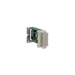
Altivar Soft Starter ATS480 is intended to start and stop asynchronous motors supplied from 208V to 690V. It meets the requirements of the most demanding applications in normal and heavy duty. With an operational rated current of 170A in normal duty, it supplies motor from 45kW to 160kW according to mains voltage. Designed for digitization, connected, optimized to meet cybersecurity standard, it simplifies project execution and maximizes the availability of applications. Its torque control (TCS) masters acceleration and deceleration. It efficiently stops high inertia application thanks to the dynamic braking and DC injection. It could be connected in-line or inside the delta to reduce its operational current. The embedded test routine simplifies the commissioning inside the delta. Its dimensions are 200mm (width) x 272mm (depth) x 340mm (height) and it weighs 12,4kg. Altivar Soft Starter ATS480 is designed to address process, infrastructures and industrial machines. It conforms to IEC/EN60947-4-1. It is certified CE, cULus, UKCA, CCC, RCM, EAC, and Marine certified DNV, ABS, BV and CCS. Display terminals, remote mounting kit, communication modules are common with Altivar Drives. Line chokes, DNV kits are common with ATS48. ATS480 is compatible with ATS48, it has same footprint, fixing, torque control algorithm, I/O, menus⦠The integration of Altivar Soft Starter ATS480 in EcoStruxure drastically simplifies architecture selection, detailed design and execution in automation and electrical systems.
Main
| Characteristic | Value(s) |
|---|---|
| Range of Product | Altivar Soft Starter ATS480 |
| Product or Component Type | Soft starter |
| Product destination | Asynchronous motors |
| Product Specific Application | Process and infrastructures |
| Device short name | ATS480 |
| Phase | 3 phase |
| Utilisation category | AC-3A AC-53A |
| Ue power supply voltage | 208...690 V - 15...10 % |
| power supply frequency | 50...60 Hz - 20...20 % |
| [Ie] rated operational current | Normal duty 170.0 A 104 °F (40 °C)) |
| rated current in heavy duty | 140.0 A at 104 °F (40 °C) heavy duty |
| Torque control | True |
| IP Degree of Protection | IP00 |
| Motor power kW | 45.0 kW 230 V in the motor supply line normal duty 37.0 kW 230 V in the motor supply line heavy duty 90.0 kW 400 V in the motor supply line normal duty 75.0 kW 400 V in the motor supply line heavy duty 90.0 kW 440 V in the motor supply line normal duty 75.0 kW 440 V in the motor supply line heavy duty 110.0 kW 500 V in the motor supply line normal duty 90.0 kW 500 V in the motor supply line heavy duty 110.0 kW 525 V in the motor supply line normal duty 90.0 kW 525 V in the motor supply line heavy duty 132.0 kW 660 V in the motor supply line normal duty 110.0 kW 660 V in the motor supply line heavy duty 160.0 kW 690 V in the motor supply line normal duty 110.0 kW 690 V in the motor supply line heavy duty 90.0 kW 230 V to the motor delta terminals normal duty 75.0 kW 230 V to the motor delta terminals heavy duty 132.0 kW 400 V to the motor delta terminals normal duty 110.0 kW 400 V to the motor delta terminals heavy duty |
| Maximum Horse Power Rating | 50.0 hp 208 V normal duty 40.0 hp 208 V heavy duty 60.0 hp 230 V normal duty 50.0 hp 230 V heavy duty 125.0 hp 460 V normal duty 100.0 hp 460 V heavy duty 150.0 hp 575 V normal duty 125.0 hp 575 V heavy duty |
| Option card | Communication module Profibus DP V1 Communication module Modbus TCP/EtherNet/IP Communication module CANopen daisy chain Communication module CANopen Sub-D Communication module CANopen open style Communication module PROFINET |
Complementary
| Characteristic | Value(s) |
|---|---|
| Device connection | In the motor supply line To the motor delta terminals |
| [Us] control circuit voltage | 110...230 V AC 50/60 Hz - 15...10 % |
| Apparent power | 0.09 kVA |
| Integrated motor overload protection | True |
| motor thermal protection class | Class 10E |
| Protection type | Phase failure line Integrated thermal protection motor Thermal protection starter Current overload motor Underload motor Excessive starting time, locked rotor motor Motor phase loss motor Line supply phase loss line Line supply phase loss motor Thermal protection motor |
| current limiting %In (5 x Ie maximum) | 150â¦700 % |
| [In] Rated current pwr loss specifctn | 170.0 A |
| Power loss static current independent | 25.0 W |
| Power loss per device current dependent | 459.0 W |
| Standards | IEC 60947-4-2 UL 60947-4-2 IEC 60664-1 |
| Product Certifications | CE cULus CCC UKCA RCM EAC DNV ABS BV CCS |
| Marking | CE CCC UKCA EAC RCM CULus |
| [Uc] control circuit voltage | 24 V DC |
| Discrete input number | 4 |
| Discrete input type | STOP) logic inputs, 3500 Ohm RUN) logic inputs, 3500 Ohm DI3) programmable as logic input, 3500 Ohm DI4) programmable as logic input, 3500 Ohm |
| Input compatibility | STOP discrete input level 1 PLC IEC 61131-2 RUN discrete input level 1 PLC IEC 61131-2 DI3 discrete input level 1 PLC IEC 61131-2 DI4 discrete input level 1 PLC IEC 61131-2 |
| Discrete input logic | Programmable digital input < 5 V |
| Relay output number | 3 |
| Relay output type | Relay outputs R1A 1 NO Relay outputs R1B 1 NO Relay outputs RIC NO/NC programmable |
| Minimum switching current | 100 mA 12 V DC relay outputs |
| Maximum switching current | Relay outputs 2 A 250 V AC Relay outputs 2 A 30 V DC Relay outputs |
| Discrete output number | 2 |
| Discrete output type | DQ1) programmable digital output <= 30 V DQ2) programmable digital output <= 30 V |
| Output compatibility | Open collector level 1 PLC IEC 65A-68 |
| Analogue input number | 1 |
| Analogue input type | AI1/PTC PTC/Pt 100 temperature probe PTC2 PTC/Pt 100 temperature probe PTC3 PTC/Pt 100 temperature probe |
| Analogue output number | 1 |
| Analogue output type | Current output AQ1 0...20 mA or 0...10 V 500 Ohm |
| Communication Port Protocol | Modbus serial |
| Connector Type | 1 RJ45 |
| Communication data link | Serial |
| Physical interface | 2-wire RS 485 |
| Transmission Rate | 1200...256000 bit/s |
| Transmission frame | RTU |
| Data format | 8 bits, configurable odd, even or no parity |
| Type of polarization | No impedance Modbus serial |
| Number of addresses | 0â¦227 Modbus serial |
| Method of access | Slave Modbus serial |
| Function Available | External bypass control Pre-heating Smoke extraction Multi-motor cascade Second motor set User management Ports and services hardening Security event logging Cybersecure firmware update Single direction |
| Display screen available | True |
| Operating position | Vertical +/- 10 degree |
| Height | 13.4 in (340.0 mm) |
| Width | 7.9 in (200.0 mm) |
| Depth | 10.7 in (272.0 mm) |
| Product Weight | 27.3 lb(US) (12.4 kg) |
Advanced open touchscreen panel - 8"4 Open

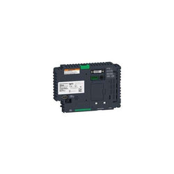
This product is part of the PacDrive 3 range, an offer of motion controllers for automating machines/lines. This motion controller offers 130 axis, 20 discrete inputs, 4 for interrupt input and 16 for touch probe input conforming to IEC 61131-2 type 1. It is a motion controller with a rated supply voltage of 24VDC, a discrete output current of 250mA and a power consumption of 36W. It is an IP20 rated product. Its dimensions are 100mm (width) x 243mm (depth) x 310mm (height). It weighs 3.5kg. This product is certified by CULus, CSA, CE, EAC. It meets CSA C22.2 No 14, CSA C22.2 No 274, EN/IEC 61131-2, UL 508C standards. Motion controllers for automating machines/lines with 0 - 130 servo or robot axes. PacDrive 3 LMC controllers provide scalable performance for synchronizing up to 130 servo axes at 1msnetwork update rate and for up to 255 virtual axes.
Main
| Characteristic | Value(s) |
|---|---|
| Range of Product | PacDrive 3 |
| Product or Component Type | Motion controller |
Complementary
| Characteristic | Value(s) |
|---|---|
| Product Compatibility | LMC802 |
| Number of axis | 130 |
| Discrete input number | 20 digital input IEC 61131-2 Type 1 4 interrupt input IEC 61131-2 Type 1 16 touch probe input IEC 61131-2 Type 1 |
| Discrete input voltage | 0...6 V 20...33 V |
| Discrete input voltage type | DC |
| Analogue input number | 2 |
| Analogue input type | Voltage analog input - 10...10 V Current analog input - 20...20 mA |
| Analogue input resolution | 12 bits |
| Discrete input current | 5 mA digital input 5 mA interrupt input 5 mA touch probe input |
| Input impedance | 100000 Ohm analog input 500 Ohm |
| Anti bounce filtering | 1 ms or 5 ms configurable digital input 100 µs touch probe input 0.1 ms or 1 ms configurable interrupt input |
| Discrete output number | 16 digital output 2 analog output |
| Discrete output current | 250 mA digital output |
| Maximum leakage current | 0.4 mA |
| Maximum Number of I/O Expansion Module | 2 |
| [Us] rated supply voltage | 24 V DC |
| Power Consumption in W | 36 W |
| Memory Type | 256 kB NVRAM 1 GB RAM DDR3L |
| Programming language | SFC (sequential function chart) FBD (function block diagram) IL (instruction list) CFC (continuous function chart) ST (structured text) LD (ladder) |
| Integrated connection type | 2 Ethernet port RJ45 Sercos 1 CAN port SUB-D 9 CANopen 1 USB port USB type A 2 Ethernet port RJ45 RT-Ethernet (real-time) 1 Ethernet port RJ45 PacNet 1 port SUB-D 9 Profibus DP 1 COM1 serial link SUB-D 9 RS232 1 COM2 serial link SUB-D 9 RS422/RS485 1 port SUB-D 9 master encoder 1 Ethernet port RJ45 Ethernet 10/100/1000BASE-T, FTP/HTTP |
| Supply | Power supply 24 VDC, <1 A |
| Width | 3.9 in (100 mm) |
| Height | 12.2 in (310 mm) |
| Depth | 9.6 in (243 mm) |
| Product Weight | 7.7 lb(US) (3.5 kg) |
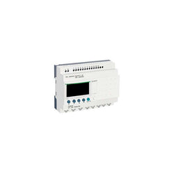
This Schneider Electric Zelio Logic SR2 compact smart relay / programmable controller uses a supply voltage of 100 to 240 volts alternating current, has 20 inputs / outputs. It also comes with screw-clamp terminals, has an integrated clock and LCD display. This compact programmable relay is ideal for management, remote control or monitoring of simple automation systems. It is suitable for both industrial and commercial applications. It has compact form-factor, allowing installation on DIN rail. It also offers simple programming, display and diagnosing of malfunctions display and navigation buttons. Simple ladder programming, adapted for non-specialists. Discovery package, coming with Zelio Soft programming software, the simplest way to learn and use this relay. Built-in EEPROM flash memory for data backup up to 10 years, easy-to-recover after a power shortage or incident. This product meets EN/IEC 61000-4-6 level 3, EN/IEC 61000-4-11, EN/IEC 60068-2-27 Ea, EN/IEC 61000-4-5, EN/IEC 60068-2-6 Fc, EN/IEC 61000-4-12, EN/IEC 61000-4-2 level 3, EN/IEC 61000-4-3 and EN/IEC 61000-4-4 level 3 standards. Simple to select, install and program, Zelio Logic is suitable for all your applications. Flexible, it offers you the choice of 2 ranges, compact or modular, extendable and 2 programming languages (FBD or LADDER). Easy to use, Zelio Logic provides a real alternative to solutions based on cabled logic or specific cards.
Main
| Characteristic | Value(s) |
|---|---|
| Range of Product | Zelio Logic |
| Product or Component Type | Compact smart relay |
Complementary
| Characteristic | Value(s) |
|---|---|
| Local display | With |
| Number or control scheme lines | 0â¦240 ladder 0â¦500 FBD |
| Cycle time | 6â¦90 ms |
| Backup time | 10 years 77 °F (25 °C) |
| Clock drift | 12 min/year 32â¦131 °F (0â¦55 °C) 6 s/month 77 °F (25 °C) |
| Checks | Program memory on each power up |
| [Us] rated supply voltage | 100...240 V AC |
| Supply voltage limits | 85â¦264 V |
| Supply frequency | 50/60 Hz |
| Maximum supply current | 100 mA 100 V without extension) 50 mA 240 V without extension) |
| Power consumption in VA | 11 VA without extension |
| Isolation voltage | 1780 V |
| Protection Type | Against inversion of terminals (control instructions not executed) |
| Discrete input number | 12 |
| Discrete input voltage | 100...240 V AC |
| Discrete input current | 0.6 mA |
| Discrete input frequency | 57...63 Hz 47...53 Hz |
| Voltage state 1 guaranteed | >= 79 V discrete input |
| Voltage state 0 guaranteed | <= 40 V discrete input |
| Current state 1 guaranteed | >= 0.17 mA discrete input) |
| Current state 0 guaranteed | <= 0.5 mA discrete input) |
| Analogue input number | 0 |
| Input impedance | 350 kOhm discrete input |
| Number of Outputs | 8 relay |
| Output voltage limits | 5...30 V DC relay output) 24...250 V AC |
| Contacts type and composition | NO relay output |
| Output thermal current | 8 A for all 8 outputs relay output |
| Electrical durability | AC-12 500000 cycles 230 V, 1.5 A relay output IEC 60947-5-1 AC-15 500000 cycles 230 V, 0.9 A relay output IEC 60947-5-1 DC-12 500000 cycles 24 V, 1.5 A relay output IEC 60947-5-1 DC-13 500000 cycles 24 V, 0.6 A relay output IEC 60947-5-1 |
| Switching capacity in mA | >= 10 mA 12 V relay output) |
| Operating rate in Hz | 0.1 Hz at Ie)relay output 10 Hz no load)relay output |
| Mechanical durability | 10000000 cycles relay output |
| [Uimp] rated impulse withstand voltage | 4 kV EN/IEC 60947-1 and EN/IEC 60664-1 |
| Clock | With |
| Response time | 50 ms ladder from state 0 to state 1)discrete input 50 ms ladder from state 1 to state 0)discrete input 50...255 ms FBD from state 0 to state 1)discrete input 50...255 ms FBD from state 1 to state 0)discrete input 10 ms from state 0 to state 1)relay output 5 ms from state 1 to state 0)relay output |
| Connections - terminals | Screw terminals, 1 x 0.2...1 x 2.5 mm² AWG 25...AWG 14) semi-solid Screw terminals, 1 x 0.2...1 x 2.5 mm² AWG 25...AWG 14) solid Screw terminals, 1 x 0.25...1 x 2.5 mm² AWG 24...AWG 14) flexible with cable end Screw terminals, 2 x 0.2...2 x 1.5 mm² AWG 24...AWG 16) solid Screw terminals, 2 x 0.25...2 x 0.75 mm² AWG 24...AWG 18) flexible with cable end |
| Tightening torque | 4.4 lbf.in (0.5 N.m) |
| Overvoltage category | III conforming to IEC 60664-1 |
| Product Weight | 0.84 lb(US) (0.38 kg) |

Main
| Characteristic | Value(s) |
|---|---|
| Range of Product | Harmony XB4 |
| Product or Component Type | Complete emergency switching off push-button |
| Device short name | XB4 |
| Bezel material | Chromium plated metal |
| Fixing collar material | Zamak |
| Mounting diameter | 0.9 in (22 mm) |
| Sale per indivisible quantity | 1 |
| Shape of signaling unit head | Round |
| Type of operator | mechanical latching |
| Head type | Standard |
| Reset | Turn to release |
| Operator profile | Red mushroom à 40 mm, unmarked |
| Contact operation | Slow-break |
| Connections - terminals | Screw clamp terminals, <= 2 x 1.5 mm² with cable end EN 60947-1 Screw clamp terminals, >= 1 x 0.22 mm² without cable end EN 60947-1 |
Complementary
| Characteristic | Value(s) |
|---|---|
| Height | 1.9 in (47 mm) |
| Width | 1.6 in (40 mm) |
| Depth | 3.2 in (82 mm) |
| Terminals description ISO n°1 | (21-22)NC |
| Product Weight | 0.260 lb(US) (0.118 kg) |
| Resistance to high pressure washer | 1015.3 psi (7000000 Pa) 131 °F (55 °C) 0.1 m |
| Contacts usage | Standard contacts |
| Positive opening | With EN/IEC 60947-5-1 appendix K |
| Operating travel | 0.06 in (1.5 mm) NC changing electrical state) 0.2 in (4.3 mm) total travel) |
| Mechanical durability | 3000000 cycles |
| Tightening torque | 7.08â¦10.6 lbf.in (0.8â¦1.2 N.m) EN 60947-1 |
| Shape of screw head | Cross Philips no 1 Cross pozidriv No 1 Slotted flat à 4 mm Slotted flat à 5.5 mm |
| Contacts material | Silver alloy (Ag/Ni) |
| Short-circuit protection | 10 A cartridge fuse gG EN/IEC 60947-5-1 |
| [Ith] conventional free air thermal current | 10 A EN/IEC 60947-5-1 |
| [Ui] rated insulation voltage | 600 V 3)EN 60947-1 |
| [Uimp] rated impulse withstand voltage | 6 kV EN 60947-1 |
| [Ie] rated operational current | 3 A 240 V, AC-15, A600 EN/IEC 60947-5-1 6 A 120 V, AC-15, A600 EN/IEC 60947-5-1 0.1 A 600 V, DC-13, Q600 EN/IEC 60947-5-1 0.27 A 250 V, DC-13, Q600 EN/IEC 60947-5-1 0.55 A 125 V, DC-13, Q600 EN/IEC 60947-5-1 1.2 A 600 V, AC-15, A600 EN/IEC 60947-5-1 |
| Electrical durability | 1000000 cycles, AC-15, 2 A 230 V 3600 cyc/h 0.5 EN/IEC 60947-5-1 appendix C 1000000 cycles, AC-15, 3 A 120 V 3600 cyc/h 0.5 EN/IEC 60947-5-1 appendix C 1000000 cycles, AC-15, 4 A 24 V 3600 cyc/h 0.5 EN/IEC 60947-5-1 appendix C 1000000 cycles, DC-13, 0.2 A 110 V 3600 cyc/h 0.5 EN/IEC 60947-5-1 appendix C 1000000 cycles, DC-13, 0.5 A 24 V 3600 cyc/h 0.5 EN/IEC 60947-5-1 appendix C |
| Electrical reliability | Î < 10exp(-6) 5 V 1 mA in clean environment EN/IEC 60947-5-4 Î < 10exp(-8) 17 V 5 mA in clean environment EN/IEC 60947-5-4 |
| Device presentation | Complete product |

This input base is part of the Modicon Momentum range, an offer of controller and IP20 monoblock I/Os for distributed control architecture. This analog input base offers 4 inputs with a full 16bit signed resolution. It offers differential analog input ranges from ±100mV, ±25mV. There is an isolation between channels and bus, channels and ground at 500V AC. It is furnished with 2 removable terminal blocks for electrical connection. It features 4 LEDs for channel status signaling. Its dimensions are 141.5mm (width) x 47.5mm (depth) x 125mm (height). It weighs 0.215kg. The main application of this module is infrastructures and energy, material handling, simple machine control. This product is certified by CE, FM Class 1 Division 2, CSA and UL. It is suitable for wall mount. Momentum is a flexible, modular family of components that easily snaps together and can be configured for a wide range of distributed I/O and control applications. System with 4 fundamental components that easily snap together in various combinations to form versatile control systems or sub-systems.
Main
| Characteristic | Value(s) |
|---|---|
| Range of Product | Modicon Momentum automation platform |
| Product or Component Type | Analogue input base |
| Analogue input number | 4 |
| Analogue Input Type | Differential |
| Analogue Input Range | +/- 100 mV 15 bits + sign > 10000 kOhm +/- 25 mV 15 bits + sign > 10000 kOhm |
| Thermocouple type | Thermocouple E Thermocouple S Thermocouple K Thermocouple N Thermocouple B Thermocouple R Thermocouple J Thermocouple T |
Complementary
| Characteristic | Value(s) |
|---|---|
| Data format | Full 16 bits signed |
| Absolute accuracy error | +/- 21 µV 77 °F (25 °C) +/- 25 mV +/- 27 µV 77 °F (25 °C) +/- 100 mV +/- 46 µV 140 °F (60 °C) +/- 25 mV +/- 94 µV 140 °F (60 °C) +/- 100 mV |
| Temperature probe type | Ni 100 0.125 mA +/- 25 mV Ni 1000 0.125 mA +/- 100 mV Pt 100 0.125 mA +/- 25 mV Pt 1000 0.125 mA +/- 100 mV |
| Update time | 500 ms |
| Isolation between channels | 400 V DC |
| Isolation between channels and ground | 500 V AC for 1 minute |
| Isolation between supply and ground | 500 V for 1 minute |
| Permissible common mode voltage | 100 V DC between channels to ground 115 V AC single or three phases between channels 200 V DC between channels 250 V AC between channels to ground 250 V AC single phase between channels |
| Common mode rejection | 120 dB DC between channels 130 dB 50 Hz AC between channels 135 dB DC between channels to ground 140 dB 60 Hz AC between channels 145 dB 50 Hz AC between channels to ground 155 dB 60 Hz AC between channels to ground |
| Serial mode rejection | 35 dB 50 Hz AC 45 dB 60 Hz AC |
| External power requirement | +/- 30 V DC |
| Maximum power dissipation in W | 5.5 W |
| Reverse polarity protection | Internal |
| Protection type | Internal 2 A slow-blow |
| Associated fuse rating | 500 mA, fast blow |
| Marking | CE |
| Local signalling | 4 LEDs for channel status |
| Electrical connection | 2 connectors for removable terminal blocks |
| Current consumption | 305 mA 24 V DC |
| Depth | 1.9 in (47.5 mm) |
| Height | 4.9 in (125 mm) |
| Width | 5.6 in (141.5 mm) |
| Product Weight | 0.474 lb(US) (0.215 kg) |

remote transmitter module TM3 - bus
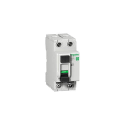
Multi 9 - GFP - RCCB - 2P - 40A - class A SI - 480Y/277 V - 26 mA instantaneous

module TM3 - 8 inputs
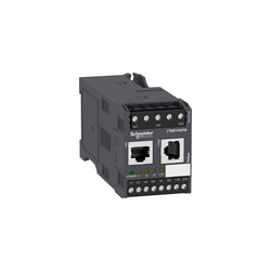
TeSys T is a motor management system that provides full motor monitoring, control, and protection when used with short circuit protection and a contactor. TeSys T manages most critical processes while reducing downtime and increasing productivity. TeSys T is a flexible system that integrates seamlessly into your automation system through five major communication protocols. TeSys T predicts what will happen in the process, as it accurately monitors current, voltage, and power over a wide range. TeSys T has a number of components that increase the flexibility of the system. This expansion module adds functionalities to the TeSys T controller. It adds voltage mesurement between phases up to 690 V nominal and 4 additional inputs. Module has 4 discrete logic inputs. 120 to 240 VAC is used to power the module. Module has the following certifications: UL, CSA NOM, ATEX, BV, EAC, RINA, LROS, DNV, ABS, GL, KERI, RMRoS, C-Tick and CCC.
Main
| Characteristic | Value(s) |
|---|---|
| Range | TeSys |
| product name | TeSys T |
| Device short name | LTME |
| Product or Component Type | Extension module |
| Device Application | Equipment monitoring and control |
| Range compatibility | TeSys TeSys T LTMR motor controller |
| Supply | Via the controller |
Complementary
| Characteristic | Value(s) |
|---|---|
| [Ui] rated insulation voltage | 690 V EN/IEC 60947-1 690 V CSA C22.2 No 14 690 V UL 508 |
| [Uimp] rated impulse withstand voltage | 4 kV supply, inputs and outputs EN/IEC 60947-4-1 6 kV current or voltage measurement circuit EN/IEC 60947-4-1 |
| Logic input number | 4 |
| Input current | 3.1 mA 100 V 7.5 mA 240 V |
| Current state 0 guaranteed | Logic input 0...40 V 2...15 mA 25 ms |
| Current state 1 guaranteed | Logic input 79...264 V <= 15 mA 25 ms |
| maximum output switching frequency | 2 Hz |
| Maximum operating rate | 1800 cyc/h |
| Contacts type and composition | Without |
| Metering type | Imbalance voltage Active power P, P1, P2, P3 Calculated active and reactive energy (+/- W.h, +/- VAR.h) Voltage U21, U32, U13, V1, V2, V3 Reactive power Q, Q1, Q2, Q3 Frequency Power factor |
| Measurement accuracy | 1 % voltage 100...830 V) 3 % power factor 5 % active and reactive power |
| Overvoltage category | III |
| Connection pitch | 0.20 in (5.08 mm) |
| Connections - terminals | Control circuit connector 1 0.0004â¦0.004 in² (0.25â¦2.5 mm²) AWG 24...AWG 14)flexible with cable end Control circuit connector 1 0.0003â¦0.004 in² (0.2â¦2.5 mm²) AWG 24...AWG 14)flexible without cable end Control circuit connector 1 0.0004â¦0.004 in² (0.25â¦2.5 mm²) AWG 24...AWG 14)flexible without cable end Control circuit connector 1 0.0003â¦0.004 in² (0.2â¦2.5 mm²) AWG 24...AWG 14)solid without cable end Control circuit connector 2 0.0003â¦0.002 in² (0.2â¦1 mm²) AWG 24...AWG 14)flexible with cable end Control circuit connector 2 0.0003â¦0.002 in² (0.2â¦1.5 mm²) AWG 24...AWG 14)flexible without cable end Control circuit connector 2 0.0008â¦0.002 in² (0.5â¦1.5 mm²) AWG 24...AWG 14)flexible without cable end Control circuit connector 2 0.0003â¦0.002 in² (0.2â¦1 mm²) AWG 24...AWG 14)solid without cable end |
| Tightening torque | Control circuit: 4.4â¦5.3 lbf.in (0.5â¦0.6 N.m) flat screwdriver 0.1 in (3 mm) |
| pollution degree | 3 |
| Electromagnetic compatibility | Electrostatic discharge, 3, 8 kV air, 6 kV contact, conforming to EN/IEC 61000-4-2 Fast transients immunity test (other circuits), level 3, 2 kV, conforming to EN/IEC 61000-4-4 Fast transients immunity test (on supply and relay outputs), level 4, 4 kV, conforming to EN/IEC 61000-4-4 Conducted RF disturbances, 10 V, conforming to EN/IEC 61000-4-6 Control circuit: surges (serial mode), 1 kV, conforming to EN/IEC 61000-4-5 Communication: surges (common mode), 2 kV, conforming to EN/IEC 61000-4-5 Voltage inputs: surges (serial mode), 2 kV, conforming to EN/IEC 61000-4-5 Voltage inputs: surges (common mode), 4 kV, conforming to EN/IEC 61000-4-5 Control circuit: surges (common mode), 2 kV, conforming to EN/IEC 61000-4-5 |
| Width | 1.8 in (45 mm) |
| Height | 2.4 in (61 mm) |
| Depth | 4.8 in (120.7 mm) |
| Product Weight | 0.46 lb(US) (0.21 kg) |
| Compatibility code | LTME |

Extendable PLC base Twido 24 V - 12 I 24 V DC - 8 O solid state
Push-button 4-gang plus with room temp. ctrl unit, stainless steel, Artec
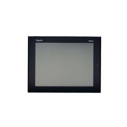
Open BOX for Universal Panel
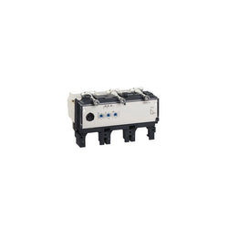
This Micrologic 2.3 is a 3 poles 3d electronic trip unit used on Compact NSX 400/630 circuit breakers. This 400A rating electronic trip unit is an optimum choice for all standard and specific applications. It embeds an adjustable long time protection against overloads. It provides also an adjustable short-time protection and a fixed instantaneous protection against short-circuits. Micrologic 2.3 indicates overloads with Alarm LEDs. The green Ready LED flashes if the circuit breaker is ready to trip. This product is part of our EcoStruxure Power architecture if associated with PowerTag NSX and Compact NSX basic frame.
Main
| Characteristic | Value(s) |
|---|---|
| Range | ComPact |
| Range of Product | ComPact NSX400...630 |
| Product or Component Type | Trip unit |
| Trip unit name | MicroLogic 2.3 |
| Trip unit technology | Electronic |
| Range Compatibility | ComPact NSX400 ComPact NSX630 |
| Device Application | Distribution |
| Number of poles | 3P |
| Protected poles description | 3t |
| Trip unit protection functions | LSoI |
| Protection type | L : for overload protection (long time) So : for short time short-circuit protection with fixed delay I : for instantaneous short-circuit protection |
| Trip unit rated current | 400 A 104 °F (40 °C) |
| [Ue] rated operational voltage | 690 V AC 50/60 Hz |
| Network type | AC |
| Network Frequency | 50/60 Hz |
Complementary
| Characteristic | Value(s) |
|---|---|
| Long-time pick-up adjustment type Ir (thermal protection) | Adjustable 9 settings |
| [Ir] long-time protection pick-up adjustment range | 160...400 A |
| Long-time protection delay adjustment type tr | Fixed |
| [tr] long-time protection delay adjustment range | 11 s 7.2 x Ir 16 s 6 x Ir 400 s 1.5 x Ir |
| Thermal memory | 20 minutes before and after tripping |
| Short-time protection pick-up adjustment type Isd | Adjustable 9 settings |
| [Isd] Short-time protection pick-up adjustment range | 1.5...10 x Ir |
| Short-time protection delay adjustment type tsd | Fixed |
| [tsd] Short-time protection delay adjustment range | 0.02 s |
| Instantaneous protection pick-up adjustment type Ii | Fixed |
| [Ii] instantaneous protection pick-up adjustment range | 4800 A |
| Earth-leakage protection | Without |
| Zone selective interlocking ZSI | Without |
| Local signalling | Flashing LED (green) for ready to operate LED 105 % Ir (red) for overload LED 90 % Ir (orange) for overload |
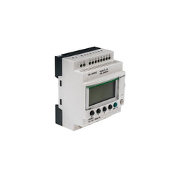
compact smart relay Zelio Logic - 12 I O - 100..240 V AC - clock - display

This Harmony RM22-UA relay allows monitoring of voltage control in single phase networks. This modular multi function single phase voltage control relay is ideal for monitoring of electrical values in industrial and building control panels. It applies to a wide type of industrial automation applications such as hoisting, packaging, lifts, textile, water. It has one of market slim form-factors with 22.5mm width, allowing for a flexible and easy installation on DIN rail, using the same space as any modular 1-pole DIN device. It also offers a diagnostic button, sealable cover, simple and precise settings with screw trimmers. It provides automatic shutdown management and fault information to user for a quick fault identification and troubleshooting. multi function controller for wide choice selected in hard-wired logic automated systems, ideal for refurbishment of old installations without using a PLC.
Main
| Characteristic | Value(s) |
|---|---|
| Range of Product | Harmony Control Relays |
| Relay Type | Voltage control relay |
| Product or Component Type | Voltage control relay |
| Phase | 1 phase |
| Supply circuit type | DC |
| Relay name | RM22UA |
| Relay monitored parameters | Undervoltage and overvoltage in window mode Overvoltage or undervoltage detection |
| time delay | Adjustable 0.1...30 s, +/- 10 % of the full scale value Tt- time delay upon fault |
| Switching capacity in VA | 2000 VA |
| Measurement range | 15...500 V AC/DC |
| Contacts type and composition | 2 C/O |
Complementary
| Characteristic | Value(s) |
|---|---|
| Reset time | 1500 ms at maximum voltage |
| Maximum switching voltage | 250 V AC |
| Minimum switching current | 10 mA 5 V DC |
| Maximum switching current | 8 A AC |
| Supply voltage limits | 20.4â¦264 V AC/DC |
| Power consumption in VA | 3.5 VA AC |
| Maximum power consumption in W | 1.5 W DC |
| Immunity to microbreaks | 10 ms |
| Resistance across terminals | 150 kOhm E2-M terminals 300 kOhm E1-M terminals 500 kOhm E3-M terminals |
| Output contacts | 2 C/O |
| nominal output current | 8 A |
| Hysteresis | 3 % fixed full scale for window mode 5â¦50 % adjustable threshold setting |
| delay at power up | 600 ms |
| Maximum measuring cycle | 100 ms measurement cycle as true rms value |
| Repeat accuracy | +/- 0.5 % input and measurement circuit +/- 2 % time delay |
| Measurement error | < 1 % over the whole range with voltage variation 0.05 %/°C with temperature variation |
| Response time | <= 500 ms |
| Insulation resistance | > 100 MOhm 500 V DC |
| Overvoltage category | III conforming to IEC 60664-1 |
| Insulation | Between supply and measurement |
| Connections - terminals | Screw terminals, 2 x 0.5...2 x 2.5 mm² AWG 20...AWG 14) solid without cable end Screw terminals, 2 x 0.2...2 x 1.5 mm² AWG 24...AWG 16) flexible with cable end Screw terminals, 1 x 0.5...1 x 3.3 mm² AWG 20...AWG 12) solid without cable end Screw terminals, 1 x 0.2...1 x 2.5 mm² AWG 24...AWG 14) flexible with cable end |
| Tightening torque | 5.3â¦8.9 lbf.in (0.6â¦1 N.m) IEC 60947-1 |
| Housing material | Self-extinguishing plastic |
| Mounting support | 35 mm DIN rail conforming to IEC 60715 |
| Electrical durability | 100000 cycles |
| Mechanical durability | 10000000 cycles |
| Utilisation category | AC-15 IEC 60947-5-1 DC-13 IEC 60947-5-1 AC-1 IEC 60947-4-1 DC-1 IEC 60947-4-1 |
| [Un] rated nominal voltage | 24...240 V AC/DC 50/60 Hz, non self-powered |
| Safety reliability data | MTTFd = 308.2 years B10d = 290000 |
| Contacts material | Cadmium free |
| Control Type | With test button |
| Width | 0.9 in (22.5 mm) |
| Product Weight | 0.24 lb(US) (0.11 kg) |
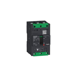
circuit breaker Compact NSXm F (36 kA at 415 VAC), 3P, 80 A rating TMD trip unit, compression lugs and busbar connectors
Modicon - processor PL7 double format - 1000mA
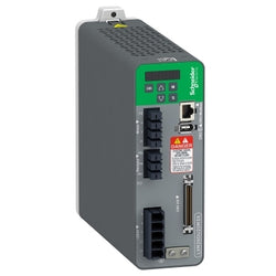
Motion Servo Drive - Lexium 26 - Three Phase 200...230 V - 2 Kw
Main
| Characteristic | Value(s) |
|---|---|
| Range of product | Modicon TSX Micro automation platform |
| Product or component type | Analog output module |
| Number of channels | 4 |
| Analogue output type | +/- 10 V 0...10 V |
Complementary
| Characteristic | Value(s) |
|---|---|
| Analog/digital conversion | 11 bits 0...10 V 11 bits + sign +/- 10 V |
| Response time | 400 µs |
| Output load | >= 2 Ohm |
| Protection type | Short-circuit |
| Temperature drift | 0.096 %/10 °C |
| Current consumption | 90 mA |
| Isolation voltage | 1000 V AC |
| Product weight | 0.2 kg |
TeSys Deca instantaneous auxiliary contact block, for LC.D contactors and CAD control relays with AC coils only. It provides 1NO+1NC contacts (NC mirror certified) rated up to 10A 690V AC, connection by screw clamp terminals. Clip-on side mounting, it procures high reliability and durability. TeSys Deca contactors have been designed for perfect integration into control systems. Multi standards certified (IEC, UL, CSA, CCC, EAC). TeSys Deca contactors offer quick simple setup, while maintaining a compact size. Contactors have both horsepower and Kw motor rating for international acceptance. An extennsive line of accessories makes it easy to meet the requirements of most applications. These contactors have UL, CSA, GOST, RINA, BV, CCC, DNV, GL, LROS certifications.
Main
| Characteristic | Value(s) |
|---|---|
| Range | TeSys |
| product name | TeSys Deca |
| Product or Component Type | Auxiliary contact block |
| Range compatibility | TeSys Deca LC1D09â¦95 AC coil TeSys Deca LC1D115/150 TeSys Deca LC1D40Aâ¦80A AC Coil TeSys Deca CAD AC coil TeSys F LC1F |
| Mounting Location | Side |
| Pole contact composition | 1 NO + 1 NC |
| Contacts operation | Instantaneous |
| [Ue] rated operational voltage | 690 V AC 25...400 Hz |
| [Ie] rated operational current | 6 A at 120 V AC-15 1.04 A at 690 V AC-15 0.55 A at 125 V DC-13 0.1 A at 600 V DC-13 |
| [Ui] rated insulation voltage | 690 V IEC 60947-5-1 600 V UL 600 V CSA |
| [Ith] conventional free air thermal current | 10 A (at 140 °F (60 °C)) |
| Standards | EN/IEC 60947-5-1 UL 60947-5-1 CSA C22.2 No 60947-5-1 IEC 60335-1:Clause 30.2 IEC 60335-2-40:Annex JJ UL 60335-2-40:Annex JJ |
| Product Certifications | CB Scheme UL CSA CCC EAC UKCA |
Complementary
| Characteristic | Value(s) |
|---|---|
| Irms rated making capacity | 140 A AC conforming to IEC 60947-5-1 250 A DC conforming to IEC 60947-5-1 |
| Permissible short-time rating | 100 A 1 s 120 A 500 ms 140 A 100 ms |
| Protection type | GG fuse 10 A |
| Mechanical durability | 30 Mcycles |
| Minimum switching current | 5 mA |
| Minimum switching voltage | 17 V |
| Non-overlap time | 1.5 ms on de-energisation no overlap between NC and NO contact 1.5 ms on energisation no overlap between NC and NO contact |
| Insulation resistance | > 10 MOhm |
| Connections - terminals | screw clamp terminals 1 0.002â¦0.006 in² (1â¦4 mm²)flexible with cable end screw clamp terminals 1 0.002â¦0.006 in² (1â¦4 mm²)flexible without cable end screw clamp terminals 2 0.002â¦0.004 in² (1â¦2.5 mm²)flexible with cable end screw clamp terminals 2 0.002â¦0.006 in² (1â¦4 mm²)flexible without cable end screw clamp terminals 1 0.002â¦0.006 in² (1â¦4 mm²)rigid without cable end screw clamp terminals 2 0.002â¦0.006 in² (1â¦4 mm²)rigid without cable end |
| Tightening torque | 15.05 lbf.in (1.7 N.m) flat à 6 mm 15.05 lbf.in (1.7 N.m) Philips No 2 15.05 lbf.in (1.7 N.m) pozidriv No 2 |
| Height | 3.0 in (76 mm) |
| Width | 0.5 in (12.5 mm) |
| Depth | 3.0 in (76 mm) |

- OPERATOR INTERFACE
- GP3000 SERIES
- 7.5" DISPLAY
- TFT COLOR LCD
- 2 SERIAL
- 1 USB
- ETHERNET
- 0.9 AMP
- 24 VDC
- RESOLUTION
- 640 X 480 PIXELS (VGA)
- CONFORMAL COATING
