
 1 year warranty


Ordering
1 piece
85364900
Popular Downloads
Dimensions
45 mm
110.5 mm
86 mm
0.36 kg
Technical
3
0
2
2
3P
IEC/EN 60947-1, IEC/EN 60947-4-1, UL 60335-2-40 LZGH2 A2L, UL 60947-4-1, CSA C22.2 No. 60335-2-40 LZGH2 A2L, CSA C22.2 No. 60947-4-1
Auxiliary Circuit 690 V
Main Circuit 690 V
Auxiliary Circuit 690 V
Main Circuit 690 V
Auxiliary Circuit 50 / 60 Hz
Control Circuit 50 / 60 Hz
Main Circuit 50 / 60 Hz
Auxiliary Circuit 50 / 60 Hz
Control Circuit 50 / 60 Hz
Main Circuit 50 / 60 Hz
acc. to IEC 60947-4-1, Open Contactors Θ = 40 °C 35 A
acc. to IEC 60947-5-1, Θ = 40 °C 16 A
acc. to IEC 60947-4-1, Open Contactors Θ = 40 °C 35 A
acc. to IEC 60947-5-1, Θ = 40 °C 16 A
(690 V) 40 °C 28 A
(690 V) 60 °C 28 A
(690 V) 70 °C 24 A
(690 V) 40 °C 28 A
(690 V) 60 °C 28 A
(690 V) 70 °C 24 A
(415 V) 60 °C 12 A
(440 V) 60 °C 12 A
(500 V) 60 °C 12.5 A
(690 V) 60 °C 9 A
(380 / 400 V) 60 °C 12 A
(220 / 230 / 240 V) 60 °C 12 A
(415 V) 60 °C 12 A
(440 V) 60 °C 12 A
(500 V) 60 °C 12.5 A
(690 V) 60 °C 9 A
(380 / 400 V) 60 °C 12 A
(220 / 230 / 240 V) 60 °C 12 A
(415 V) 60 °C 12 A
(440 V) 60 °C 12 A
(500 V) 60 °C 12.5 A
(690 V) 60 °C 9 A
(380 / 400 V) 60 °C 12 A
(220 / 230 / 240 V) 60 °C 12 A
(415 V) 60 °C 12 A
(440 V) 60 °C 12 A
(500 V) 60 °C 12.5 A
(690 V) 60 °C 9 A
(380 / 400 V) 60 °C 12 A
(220 / 230 / 240 V) 60 °C 12 A
(500 V) 2 A
(690 V) 2 A
(24 / 127 V) 6 A
(220 / 240 V) 4 A
(400 / 440 V) 3 A
(500 V) 2 A
(690 V) 2 A
(24 / 127 V) 6 A
(220 / 240 V) 4 A
(400 / 440 V) 3 A
(110 V) 1-Pole, 40 °C 15 A
(110 V) 1-Pole, 60 °C 15 A
(110 V) 1-Pole, 70 °C 15 A
(110 V) 2 Poles in Series, 40 °C 27 A
(110 V) 2 Poles in Series, 60 °C 27 A
(110 V) 2 Poles in Series, 70 °C 24 A
(110 V) 3 Poles in Series, 40 °C 27 A
(110 V) 3 Poles in Series, 60 °C 27 A
(110 V) 3 Poles in Series, 70 °C 24 A
(220 V) 2 Poles in Series, 40 °C 15 A
(220 V) 2 Poles in Series, 60 °C 15 A
(220 V) 2 Poles in Series, 70 °C 15 A
(220 V) 3 Poles in Series, 40 °C 27 A
(220 V) 3 Poles in Series, 60 °C 27 A
(220 V) 3 Poles in Series, 70 °C 24 A
(72 V) 1-Pole, 40 °C 27 A
(72 V) 1-Pole, 60 °C 27 A
(72 V) 1-Pole, 70 °C 24 A
(72 V) 2 Poles in Series, 40 °C 27 A
(72 V) 2 Poles in Series, 60 °C 27 A
(72 V) 2 Poles in Series, 70 °C 24 A
(72 V) 3 Poles in Series, 40 °C 27 A
(72 V) 3 Poles in Series, 60 °C 27 A
(72 V) 3 Poles in Series, 70 °C 24 A
(110 V) 1-Pole, 40 °C 15 A
(110 V) 1-Pole, 60 °C 15 A
(110 V) 1-Pole, 70 °C 15 A
(110 V) 2 Poles in Series, 40 °C 27 A
(110 V) 2 Poles in Series, 60 °C 27 A
(110 V) 2 Poles in Series, 70 °C 24 A
(110 V) 3 Poles in Series, 40 °C 27 A
(110 V) 3 Poles in Series, 60 °C 27 A
(110 V) 3 Poles in Series, 70 °C 24 A
(220 V) 2 Poles in Series, 40 °C 15 A
(110 V) 1-Pole, 40 °C 7 A
(110 V) 1-Pole, 60 °C 7 A
(110 V) 1-Pole, 70 °C 7 A
(110 V) 2 Poles in Series, 40 °C 27 A
(110 V) 2 Poles in Series, 60 °C 27 A
(110 V) 2 Poles in Series, 70 °C 24 A
(110 V) 3 Poles in Series, 40 °C 27 A
(110 V) 3 Poles in Series, 60 °C 27 A
(110 V) 3 Poles in Series, 70 °C 24 A
(220 V) 2 Poles in Series, 40 °C 7 A
(220 V) 2 Poles in Series, 60 °C 7 A
(220 V) 2 Poles in Series, 70 °C 7 A
(220 V) 3 Poles in Series, 40 °C 27 A
(220 V) 3 Poles in Series, 60 °C 27 A
(220 V) 3 Poles in Series, 70 °C 24 A
(72 V) 1-Pole, 40 °C 27 A
(72 V) 1-Pole, 60 °C 27 A
(72 V) 1-Pole, 70 °C 24 A
(72 V) 2 Poles in Series, 40 °C 27 A
(72 V) 2 Poles in Series, 60 °C 27 A
(72 V) 2 Poles in Series, 70 °C 24 A
(72 V) 3 Poles in Series, 40 °C 27 A
(72 V) 3 Poles in Series, 60 °C 27 A
(72 V) 3 Poles in Series, 70 °C 24 A
(110 V) 1-Pole, 40 °C 7 A
(110 V) 1-Pole, 60 °C 7 A
(110 V) 1-Pole, 70 °C 7 A
(110 V) 2 Poles in Series, 40 °C 27 A
(110 V) 2 Poles in Series, 60 °C 27 A
(110 V) 2 Poles in Series, 70 °C 24 A
(110 V) 3 Poles in Series, 40 °C 27 A
(110 V) 3 Poles in Series, 60 °C 27 A
(110 V) 3 Poles in Series, 70 °C 24 A
(220 V) 2 Poles in Series, 40 °C 7 A
(110 V) 1-Pole, 40 °C 4 A
(110 V) 1-Pole, 60 °C 4 A
(110 V) 1-Pole, 70 °C 4 A
(110 V) 2 Poles in Series, 40 °C 15 A
(110 V) 2 Poles in Series, 60 °C 15 A
(110 V) 2 Poles in Series, 70 °C 15 A
(110 V) 3 Poles in Series, 40 °C 27 A
(110 V) 3 Poles in Series, 60 °C 27 A
(110 V) 3 Poles in Series, 70 °C 24 A
(220 V) 2 Poles in Series, 40 °C 4 A
(220 V) 2 Poles in Series, 60 °C 4 A
(220 V) 2 Poles in Series, 70 °C 4 A
(220 V) 3 Poles in Series, 40 °C 12 A
(220 V) 3 Poles in Series, 60 °C 12 A
(220 V) 3 Poles in Series, 70 °C 12 A
(72 V) 1-Pole, 40 °C 12 A
(72 V) 1-Pole, 60 °C 12 A
(72 V) 1-Pole, 70 °C 12 A
(72 V) 2 Poles in Series, 40 °C 27 A
(72 V) 2 Poles in Series, 60 °C 27 A
(72 V) 2 Poles in Series, 70 °C 24 A
(72 V) 3 Poles in Series, 40 °C 27 A
(72 V) 3 Poles in Series, 60 °C 27 A
(72 V) 3 Poles in Series, 70 °C 24 A
(110 V) 1-Pole, 40 °C 4 A
(110 V) 1-Pole, 60 °C 4 A
(110 V) 1-Pole, 70 °C 4 A
(110 V) 2 Poles in Series, 40 °C 15 A
(110 V) 2 Poles in Series, 60 °C 15 A
(110 V) 2 Poles in Series, 70 °C 15 A
(110 V) 3 Poles in Series, 40 °C 27 A
(110 V) 3 Poles in Series, 60 °C 27 A
(110 V) 3 Poles in Series, 70 °C 24 A
(220 V) 2 Poles in Series, 40 °C 4 A
(24 V) 6 A / 144 W
(48 V) 2.8 A / 134 W
(72 V) 1 A / 72 W
(110 V) 0.55 A / 60 W
(125 V) 0.55 A / 69 W
(220 V) 0.27 A / 60 W
(250 V) 0.27 A / 68 W
(400 V) 0.15 A / 60 W
(500 V) 0.13 A / 65 W
(600 V) 0.1 A / 60 W
(24 V) 6 A / 144 W
(48 V) 2.8 A / 134 W
(72 V) 1 A / 72 W
(110 V) 0.55 A / 60 W
(125 V) 0.55 A / 69 W
(220 V) 0.27 A / 60 W
(250 V) 0.27 A / 68 W
(400 V) 0.15 A / 60 W
(500 V) 0.13 A / 65 W
(600 V) 0.1 A / 60 W
(400 V) 5.5 kW
(415 V) 5.5 kW
(440 V) 5.5 kW
(500 V) 7.5 kW
(690 V) 7.5 kW
(380 / 400 V) 5.5 kW
(220 / 230 / 240 V) 3 kW
(400 V) 5.5 kW
(415 V) 5.5 kW
(440 V) 5.5 kW
(500 V) 7.5 kW
(690 V) 7.5 kW
(380 / 400 V) 5.5 kW
(220 / 230 / 240 V) 3 kW
(415 V) 5.5 kW
(440 V) 5.5 kW
(500 V) 7.5 kW
(690 V) 7.5 kW
(380 / 400 V) 5.5 kW
(220 / 230 / 240 V) 3 kW
(415 V) 5.5 kW
(440 V) 5.5 kW
(500 V) 7.5 kW
(690 V) 7.5 kW
(380 / 400 V) 5.5 kW
(220 / 230 / 240 V) 3 kW
at 40 °C Ambient Temp, in Free Air, from a Cold State 10 s 150 A
at 40 °C Ambient Temp, in Free Air, from a Cold State 15 min 35 A
at 40 °C Ambient Temp, in Free Air, from a Cold State 1 min 60 A
at 40 °C Ambient Temp, in Free Air, from a Cold State 1 s 300 A
at 40 °C Ambient Temp, in Free Air, from a Cold State 30 s 80 A
for 0.1 s 140 A
for 1 s 100 A
cos phi=0.45 (cos phi=0.35 for Ie > 100 A) at 440 V 250 A
cos phi=0.45 (cos phi=0.35 for Ie > 100 A) at 690 V 106 A
cos phi=0.45 (cos phi=0.35 for Ie > 100 A) at 440 V 250 A
cos phi=0.45 (cos phi=0.35 for Ie > 100 A) at 690 V 106 A
acc. to IEC 60947-4-1 690 V
acc. to IEC 60947-5-1 690 V
acc. to UL/CSA 600 V
acc. to IEC 60947-4-1 690 V
acc. to IEC 60947-5-1 690 V
acc. to UL/CSA 600 V
6 kV
(AC-1) 600 cycles per hour
(AC-15) 1200 cycles per hour
(AC-2 / AC-4) 300 cycles per hour
(AC-3) 1200 cycles per hour
(DC-13) 900 cycles per hour
(AC-1) 600 cycles per hour
(AC-15) 1200 cycles per hour
(AC-2 / AC-4) 300 cycles per hour
(AC-3) 1200 cycles per hour
(DC-13) 900 cycles per hour
3600 cycles per hour
50 Hz 24 ... 60 V
60 Hz 24 ... 60 V
DC Operation 20 ... 60 V
50 Hz 24 ... 60 V
60 Hz 24 ... 60 V
DC Operation 20 ... 60 V
at 6 A per Pole 0.1 W
at Rated Operating Conditions AC-1 per Pole 1 W
at Rated Operating Conditions AC-3 per Pole 0.2 W
at 6 A per Pole 0.1 W
at Rated Operating Conditions AC-1 per Pole 1 W
at Rated Operating Conditions AC-3 per Pole 0.2 W
Between Coil De-energization and NC Contact Closing 13 ... 98 ms
Between Coil De-energization and NO Contact Opening 11 ... 95 ms
Between Coil Energization and NC Contact Opening 38 ... 90 ms
Between Coil Energization and NO Contact Closing 40 ... 95 ms
Between Coil De-energization and NC Contact Closing 13 ... 98 ms
Between Coil De-energization and NO Contact Opening 11 ... 95 ms
Between Coil Energization and NC Contact Opening 38 ... 90 ms
Between Coil Energization and NO Contact Closing 40 ... 95 ms
TH35-15 (35 x 15 mm Mounting Rail) acc. to IEC 60715
TH35-7.5 (35 x 7.5 mm Mounting Rail) acc. to IEC 60715
TH35-15 (35 x 15 mm Mounting Rail) acc. to IEC 60715
TH35-7.5 (35 x 7.5 mm Mounting Rail) acc. to IEC 60715
2 x M4 Screws Placed Diagonally
Flexible with Ferrule 1/2x 0.75 ... 6 mm²
Flexible with Insulated Ferrule 1x 0.75 ... 4 mm²
Flexible with Insulated Ferrule 2x 0.75 ... 2.5 mm²
Rigid Solid 1/2x 1 ... 4 mm²
Rigid Stranded 1/2x 1 ... 6 mm²
Flexible with Ferrule 1/2x 0.75 ... 6 mm²
Flexible with Insulated Ferrule 1x 0.75 ... 4 mm²
Flexible with Insulated Ferrule 2x 0.75 ... 2.5 mm²
Rigid Solid 1/2x 1 ... 4 mm²
Rigid Stranded 1/2x 1 ... 6 mm²
Flexible with Ferrule 1/2x 0.75 ... 2.5 mm²
Flexible with Insulated Ferrule 2x 0.75 ... 1.5 mm²
Flexible with Insulated Ferrule 1x 0.75 ... 2.5 mm²
Rigid Solid 1/2x 1 ... 2.5 mm²
Rigid Stranded 1/2x 1 ... 2.5 mm²
Flexible with Ferrule 1/2x 0.75 ... 2.5 mm²
Flexible with Insulated Ferrule 2x 0.75 ... 1.5 mm²
Flexible with Insulated Ferrule 1x 0.75 ... 2.5 mm²
Rigid Solid 1/2x 1 ... 2.5 mm²
Rigid Stranded 1/2x 1 ... 2.5 mm²
Flexible with Ferrule 1/2x 0.75 ... 2.5 mm²
Flexible with Insulated Ferrule 1x 0.75 ... 2.5 mm²
Flexible with Insulated Ferrule 2x 0.75 ... 1.5 mm²
Rigid Solid 1/2x 1 ... 2.5 mm²
Rigid Stranded 1/2x 1 ... 2.5 mm²
Flexible with Ferrule 1/2x 0.75 ... 2.5 mm²
Flexible with Insulated Ferrule 1x 0.75 ... 2.5 mm²
Flexible with Insulated Ferrule 2x 0.75 ... 1.5 mm²
Rigid Solid 1/2x 1 ... 2.5 mm²
Rigid Stranded 1/2x 1 ... 2.5 mm²
Auxiliary Circuit 10 mm
Control Circuit 10 mm
Main Circuit 10 mm
Auxiliary Circuit 10 mm
Control Circuit 10 mm
Main Circuit 10 mm
acc. to IEC 60529, IEC 60947-1, EN 60529 Auxiliary Terminals IP20
acc. to IEC 60529, IEC 60947-1, EN 60529 Coil Terminals IP20
acc. to IEC 60529, IEC 60947-1, EN 60529 Main Terminals IP20
acc. to IEC 60529, IEC 60947-1, EN 60529 Auxiliary Terminals IP20
acc. to IEC 60529, IEC 60947-1, EN 60529 Coil Terminals IP20
acc. to IEC 60529, IEC 60947-1, EN 60529 Main Terminals IP20
Auxiliary Circuit 1.2 N·m
Control Circuit 1.2 N·m
Main Circuit 1.5 N·m
Auxiliary Circuit 1.2 N·m
Control Circuit 1.2 N·m
Main Circuit 1.5 N·m
Screw Terminals
Block Contactor
Technical UL/CSA
0
18 A
(115 V AC) Single Phase 1 Hp
(200 V AC) Three Phase 3 Hp
(230 V AC) Single Phase 2 Hp
(230 V AC) Three Phase 3 Hp
(460 V AC) Three Phase 5 Hp
(575 V AC) Three Phase 5 Hp
(115 V AC) Single Phase 1 Hp
(200 V AC) Three Phase 3 Hp
(230 V AC) Single Phase 2 Hp
(230 V AC) Three Phase 3 Hp
(460 V AC) Three Phase 5 Hp
(575 V AC) Three Phase 5 Hp
Main Circuit 600 V
(600 V AC) 28 A
(120 V AC) Single Phase 1 hp
(200 ... 208 V AC) Three Phase 3 hp
(220 ... 240 V AC) Three Phase 3 hp
(240 V AC) Single Phase 2 hp
(440 ... 480 V AC) Three Phase 7-1/2 hp
(550 ... 600 V AC) Three Phase 10 hp
(120 V AC) Single Phase 1 hp
(200 ... 208 V AC) Three Phase 3 hp
(220 ... 240 V AC) Three Phase 3 hp
(240 V AC) Single Phase 2 hp
(440 ... 480 V AC) Three Phase 7-1/2 hp
(550 ... 600 V AC) Three Phase 10 hp
Rigid Solid 1/2x 16-10 AWG
Rigid Stranded 1/2x 16-10 AWG
Rigid Solid 1/2x 16-10 AWG
Rigid Stranded 1/2x 16-10 AWG
Rigid Solid 1/2x 18-14 AWG
Rigid Stranded 1/2x 18-14 AWG
Rigid Solid 1/2x 18-14 AWG
Rigid Stranded 1/2x 18-14 AWG
Rigid Solid 1/2x 18-14 AWG
Rigid Stranded 1/2x 18-14 AWG
Rigid Solid 1/2x 18-14 AWG
Rigid Stranded 1/2x 18-14 AWG
Auxiliary Circuit 11 in·lb
Control Circuit 11 in·lb
Main Circuit 13 in·lb
Auxiliary Circuit 11 in·lb
Control Circuit 11 in·lb
Main Circuit 13 in·lb
(120 V AC) Single Phase 16 A
(200 ... 208 V AC) Three Phase 11 A
(220 ... 240 V AC) Three Phase 9.6 A
(240 V AC) Single Phase 12 A
(440 ... 480 V AC) Three Phase 11 A
(550 ... 600 V AC) Three Phase 11 A
(120 V AC) Single Phase 16 A
(200 ... 208 V AC) Three Phase 11 A
(220 ... 240 V AC) Three Phase 9.6 A
(240 V AC) Single Phase 12 A
(440 ... 480 V AC) Three Phase 11 A
(550 ... 600 V AC) Three Phase 11 A
Environmental
Close to Contactor Fitted with Thermal O/L Relay -25 ... 60 °C
Close to Contactor without Thermal O/L Relay -40 ... 70 °C
Close to Contactor for Storage -60 ... +80 °C
Close to Contactor Fitted with Thermal O/L Relay -25 ... 60 °C
Close to Contactor without Thermal O/L Relay -40 ... 70 °C
Close to Contactor for Storage -60 ... +80 °C
Category B according to IEC 60947-1 Annex Q
Without Derating 3000 m
Closed, Shock Direction: B1 25 g
Open, Shock Direction: B1 5 g
Shock Direction: A 30 g
Shock Direction: B2 15 g
Shock Direction: C1 25 g
Shock Direction: C2 25 g
Closed, Shock Direction: B1 25 g
Open, Shock Direction: B1 5 g
Shock Direction: A 30 g
Shock Direction: B2 15 g
Shock Direction: C1 25 g
Shock Direction: C2 25 g
4g Closed Position & 2g Open position 5 ... 300 Hz
3
Material Compliance
Following EU Directive 2011/65/EU and Amendment 2015/863 July 22, 2019
Business To Business
5. Small Equipment (No External Dimension More Than 50 cm)
ABB EcoSolutions
Recycled Cardboard - 86 %
Recycled Metal - 28 %
Certificates and Declarations
Container Information
box 1 piece
87 mm
113 mm
47 mm
0.36 kg
3471523113718
box 18 piece
250 mm
300 mm
315 mm
6.48 kg
External Classifications and Standards
Q
EC000066 - Power contactor, AC switching
EC000066 - Power contactor, AC switching
EC000066 - Power contactor, AC switching
V11.0 : 27371003
39121529
4758 >> Iec Contactors

Ordering
1 piece
85364900
Popular Downloads
Dimensions
45 mm
77 mm
86 mm
0.27 kg
Technical
3
0
1
0
3P
IEC/EN 60947-1, IEC/EN 60947-4-1, UL 60335-2-40 LZGH2 A2L, UL 60947-4-1, CSA C22.2 No. 60335-2-40 LZGH2 A2L, CSA C22.2 No. 60947-4-1
Auxiliary Circuit 690 V
Main Circuit 690 V
Auxiliary Circuit 690 V
Main Circuit 690 V
Auxiliary Circuit 50 / 60 Hz
Control Circuit 50 / 60 Hz
Main Circuit 50 / 60 Hz
Auxiliary Circuit 50 / 60 Hz
Control Circuit 50 / 60 Hz
Main Circuit 50 / 60 Hz
acc. to IEC 60947-4-1, Open Contactors Θ = 40 °C 35 A
acc. to IEC 60947-5-1, Θ = 40 °C 16 A
acc. to IEC 60947-4-1, Open Contactors Θ = 40 °C 35 A
acc. to IEC 60947-5-1, Θ = 40 °C 16 A
(690 V) 40 °C 25 A
(690 V) 60 °C 25 A
(690 V) 70 °C 22 A
(690 V) 40 °C 25 A
(690 V) 60 °C 25 A
(690 V) 70 °C 22 A
(415 V) 60 °C 9 A
(440 V) 60 °C 9 A
(500 V) 60 °C 9.5 A
(690 V) 60 °C 7 A
(380 / 400 V) 60 °C 9 A
(220 / 230 / 240 V) 60 °C 9 A
(415 V) 60 °C 9 A
(440 V) 60 °C 9 A
(500 V) 60 °C 9.5 A
(690 V) 60 °C 7 A
(380 / 400 V) 60 °C 9 A
(220 / 230 / 240 V) 60 °C 9 A
(415 V) 60 °C 9 A
(440 V) 60 °C 9 A
(500 V) 60 °C 9.5 A
(690 V) 60 °C 7 A
(380 / 400 V) 60 °C 9 A
(220 / 230 / 240 V) 60 °C 9 A
(415 V) 60 °C 9 A
(440 V) 60 °C 9 A
(500 V) 60 °C 9.5 A
(690 V) 60 °C 7 A
(380 / 400 V) 60 °C 9 A
(220 / 230 / 240 V) 60 °C 9 A
(500 V) 2 A
(690 V) 2 A
(24 / 127 V) 6 A
(220 / 240 V) 4 A
(400 / 440 V) 3 A
(500 V) 2 A
(690 V) 2 A
(24 / 127 V) 6 A
(220 / 240 V) 4 A
(400 / 440 V) 3 A
(110 V) 1-Pole, 40 °C 10 A
(110 V) 1-Pole, 60 °C 10 A
(110 V) 1-Pole, 70 °C 10 A
(110 V) 2 Poles in Series, 40 °C 25 A
(110 V) 2 Poles in Series, 60 °C 25 A
(110 V) 2 Poles in Series, 70 °C 22 A
(110 V) 3 Poles in Series, 40 °C 25 A
(110 V) 3 Poles in Series, 60 °C 25 A
(110 V) 3 Poles in Series, 70 °C 22 A
(220 V) 2 Poles in Series, 40 °C 10 A
(220 V) 2 Poles in Series, 60 °C 10 A
(220 V) 2 Poles in Series, 70 °C 10 A
(220 V) 3 Poles in Series, 40 °C 25 A
(220 V) 3 Poles in Series, 60 °C 25 A
(220 V) 3 Poles in Series, 70 °C 22 A
(72 V) 1-Pole, 40 °C 25 A
(72 V) 1-Pole, 60 °C 25 A
(72 V) 1-Pole, 70 °C 22 A
(72 V) 2 Poles in Series, 40 °C 25 A
(72 V) 2 Poles in Series, 60 °C 25 A
(72 V) 2 Poles in Series, 70 °C 22 A
(72 V) 3 Poles in Series, 40 °C 25 A
(72 V) 3 Poles in Series, 60 °C 25 A
(72 V) 3 Poles in Series, 70 °C 22 A
(110 V) 1-Pole, 40 °C 10 A
(110 V) 1-Pole, 60 °C 10 A
(110 V) 1-Pole, 70 °C 10 A
(110 V) 2 Poles in Series, 40 °C 25 A
(110 V) 2 Poles in Series, 60 °C 25 A
(110 V) 2 Poles in Series, 70 °C 22 A
(110 V) 3 Poles in Series, 40 °C 25 A
(110 V) 3 Poles in Series, 60 °C 25 A
(110 V) 3 Poles in Series, 70 °C 22 A
(220 V) 2 Poles in Series, 40 °C 10 A
(110 V) 1-Pole, 40 °C 6 A
(110 V) 1-Pole, 60 °C 6 A
(110 V) 1-Pole, 70 °C 6 A
(110 V) 2 Poles in Series, 40 °C 25 A
(110 V) 2 Poles in Series, 60 °C 25 A
(110 V) 2 Poles in Series, 70 °C 22 A
(110 V) 3 Poles in Series, 40 °C 25 A
(110 V) 3 Poles in Series, 60 °C 25 A
(110 V) 3 Poles in Series, 70 °C 22 A
(220 V) 2 Poles in Series, 40 °C 6 A
(220 V) 2 Poles in Series, 60 °C 6 A
(220 V) 2 Poles in Series, 70 °C 6 A
(220 V) 3 Poles in Series, 40 °C 25 A
(220 V) 3 Poles in Series, 60 °C 25 A
(220 V) 3 Poles in Series, 70 °C 22 A
(72 V) 1-Pole, 40 °C 25 A
(72 V) 1-Pole, 60 °C 25 A
(72 V) 1-Pole, 70 °C 22 A
(72 V) 2 Poles in Series, 40 °C 25 A
(72 V) 2 Poles in Series, 60 °C 25 A
(72 V) 2 Poles in Series, 70 °C 22 A
(72 V) 3 Poles in Series, 40 °C 25 A
(72 V) 3 Poles in Series, 60 °C 25 A
(72 V) 3 Poles in Series, 70 °C 22 A
(110 V) 1-Pole, 40 °C 6 A
(110 V) 1-Pole, 60 °C 6 A
(110 V) 1-Pole, 70 °C 6 A
(110 V) 2 Poles in Series, 40 °C 25 A
(110 V) 2 Poles in Series, 60 °C 25 A
(110 V) 2 Poles in Series, 70 °C 22 A
(110 V) 3 Poles in Series, 40 °C 25 A
(110 V) 3 Poles in Series, 60 °C 25 A
(110 V) 3 Poles in Series, 70 °C 22 A
(220 V) 2 Poles in Series, 40 °C 6 A
(110 V) 1-Pole, 40 °C 4 A
(110 V) 1-Pole, 60 °C 4 A
(110 V) 1-Pole, 70 °C 4 A
(110 V) 2 Poles in Series, 40 °C 10 A
(110 V) 2 Poles in Series, 60 °C 10 A
(110 V) 2 Poles in Series, 70 °C 10 A
(110 V) 3 Poles in Series, 40 °C 25 A
(110 V) 3 Poles in Series, 60 °C 25 A
(110 V) 3 Poles in Series, 70 °C 22 A
(220 V) 2 Poles in Series, 40 °C 4 A
(220 V) 2 Poles in Series, 60 °C 4 A
(220 V) 2 Poles in Series, 70 °C 4 A
(220 V) 3 Poles in Series, 40 °C 9 A
(220 V) 3 Poles in Series, 60 °C 9 A
(220 V) 3 Poles in Series, 70 °C 9 A
(72 V) 1-Pole, 40 °C 9 A
(72 V) 1-Pole, 60 °C 9 A
(72 V) 1-Pole, 70 °C 9 A
(72 V) 2 Poles in Series, 40 °C 25 A
(72 V) 2 Poles in Series, 60 °C 25 A
(72 V) 2 Poles in Series, 70 °C 22 A
(72 V) 3 Poles in Series, 40 °C 25 A
(72 V) 3 Poles in Series, 60 °C 25 A
(72 V) 3 Poles in Series, 70 °C 22 A
(110 V) 1-Pole, 40 °C 4 A
(110 V) 1-Pole, 60 °C 4 A
(110 V) 1-Pole, 70 °C 4 A
(110 V) 2 Poles in Series, 40 °C 10 A
(110 V) 2 Poles in Series, 60 °C 10 A
(110 V) 2 Poles in Series, 70 °C 10 A
(110 V) 3 Poles in Series, 40 °C 25 A
(110 V) 3 Poles in Series, 60 °C 25 A
(110 V) 3 Poles in Series, 70 °C 22 A
(220 V) 2 Poles in Series, 40 °C 4 A
(24 V) 6 A / 144 W
(48 V) 2.8 A / 134 W
(72 V) 1 A / 72 W
(110 V) 0.55 A / 60 W
(125 V) 0.55 A / 69 W
(220 V) 0.27 A / 60 W
(250 V) 0.27 A / 68 W
(400 V) 0.15 A / 60 W
(500 V) 0.13 A / 65 W
(600 V) 0.1 A / 60 W
(24 V) 6 A / 144 W
(48 V) 2.8 A / 134 W
(72 V) 1 A / 72 W
(110 V) 0.55 A / 60 W
(125 V) 0.55 A / 69 W
(220 V) 0.27 A / 60 W
(250 V) 0.27 A / 68 W
(400 V) 0.15 A / 60 W
(500 V) 0.13 A / 65 W
(600 V) 0.1 A / 60 W
(400 V) 4 kW
(415 V) 4 kW
(440 V) 4 kW
(500 V) 5.5 kW
(690 V) 5.5 kW
(380 / 400 V) 4 kW
(220 / 230 / 240 V) 2.2 kW
(400 V) 4 kW
(415 V) 4 kW
(440 V) 4 kW
(500 V) 5.5 kW
(690 V) 5.5 kW
(380 / 400 V) 4 kW
(220 / 230 / 240 V) 2.2 kW
(415 V) 4 kW
(440 V) 4 kW
(500 V) 5.5 kW
(690 V) 5.5 kW
(380 / 400 V) 4 kW
(220 / 230 / 240 V) 2.2 kW
(415 V) 4 kW
(440 V) 4 kW
(500 V) 5.5 kW
(690 V) 5.5 kW
(380 / 400 V) 4 kW
(220 / 230 / 240 V) 2.2 kW
at 40 °C Ambient Temp, in Free Air, from a Cold State 10 s 150 A
at 40 °C Ambient Temp, in Free Air, from a Cold State 15 min 35 A
at 40 °C Ambient Temp, in Free Air, from a Cold State 1 min 60 A
at 40 °C Ambient Temp, in Free Air, from a Cold State 1 s 300 A
at 40 °C Ambient Temp, in Free Air, from a Cold State 30 s 80 A
for 0.1 s 140 A
for 1 s 100 A
cos phi=0.45 (cos phi=0.35 for Ie > 100 A) at 440 V 250 A
cos phi=0.45 (cos phi=0.35 for Ie > 100 A) at 690 V 106 A
cos phi=0.45 (cos phi=0.35 for Ie > 100 A) at 440 V 250 A
cos phi=0.45 (cos phi=0.35 for Ie > 100 A) at 690 V 106 A
acc. to IEC 60947-4-1 690 V
acc. to IEC 60947-5-1 690 V
acc. to UL/CSA 600 V
acc. to IEC 60947-4-1 690 V
acc. to IEC 60947-5-1 690 V
acc. to UL/CSA 600 V
6 kV
(AC-1) 600 cycles per hour
(AC-15) 1200 cycles per hour
(AC-2 / AC-4) 300 cycles per hour
(AC-3) 1200 cycles per hour
(DC-13) 900 cycles per hour
(AC-1) 600 cycles per hour
(AC-15) 1200 cycles per hour
(AC-2 / AC-4) 300 cycles per hour
(AC-3) 1200 cycles per hour
(DC-13) 900 cycles per hour
3600 cycles per hour
50 Hz 48 ... 130 V
60 Hz 48 ... 130 V
DC Operation 48 ... 130 V
50 Hz 48 ... 130 V
60 Hz 48 ... 130 V
DC Operation 48 ... 130 V
at 6 A per Pole 0.1 W
at Rated Operating Conditions AC-1 per Pole 0.8 W
at Rated Operating Conditions AC-3 per Pole 0.1 W
at 6 A per Pole 0.1 W
at Rated Operating Conditions AC-1 per Pole 0.8 W
at Rated Operating Conditions AC-3 per Pole 0.1 W
Between Coil De-energization and NC Contact Closing 13 ... 98 ms
Between Coil De-energization and NO Contact Opening 11 ... 95 ms
Between Coil Energization and NC Contact Opening 38 ... 90 ms
Between Coil Energization and NO Contact Closing 40 ... 95 ms
Between Coil De-energization and NC Contact Closing 13 ... 98 ms
Between Coil De-energization and NO Contact Opening 11 ... 95 ms
Between Coil Energization and NC Contact Opening 38 ... 90 ms
Between Coil Energization and NO Contact Closing 40 ... 95 ms
TH35-15 (35 x 15 mm Mounting Rail) acc. to IEC 60715
TH35-7.5 (35 x 7.5 mm Mounting Rail) acc. to IEC 60715
TH35-15 (35 x 15 mm Mounting Rail) acc. to IEC 60715
TH35-7.5 (35 x 7.5 mm Mounting Rail) acc. to IEC 60715
2 x M4 Screws Placed Diagonally
Flexible with Ferrule 1/2x 0.75 ... 6 mm²
Flexible with Insulated Ferrule 1x 0.75 ... 4 mm²
Flexible with Insulated Ferrule 2x 0.75 ... 2.5 mm²
Rigid Solid 1/2x 1 ... 4 mm²
Rigid Stranded 1/2x 1 ... 6 mm²
Flexible with Ferrule 1/2x 0.75 ... 6 mm²
Flexible with Insulated Ferrule 1x 0.75 ... 4 mm²
Flexible with Insulated Ferrule 2x 0.75 ... 2.5 mm²
Rigid Solid 1/2x 1 ... 4 mm²
Rigid Stranded 1/2x 1 ... 6 mm²
Flexible with Ferrule 1/2x 0.75 ... 2.5 mm²
Flexible with Insulated Ferrule 2x 0.75 ... 1.5 mm²
Flexible with Insulated Ferrule 1x 0.75 ... 2.5 mm²
Rigid Solid 1/2x 1 ... 2.5 mm²
Rigid Stranded 1/2x 1 ... 2.5 mm²
Flexible with Ferrule 1/2x 0.75 ... 2.5 mm²
Flexible with Insulated Ferrule 2x 0.75 ... 1.5 mm²
Flexible with Insulated Ferrule 1x 0.75 ... 2.5 mm²
Rigid Solid 1/2x 1 ... 2.5 mm²
Rigid Stranded 1/2x 1 ... 2.5 mm²
Flexible with Ferrule 1/2x 0.75 ... 2.5 mm²
Flexible with Insulated Ferrule 1x 0.75 ... 2.5 mm²
Flexible with Insulated Ferrule 2x 0.75 ... 1.5 mm²
Rigid Solid 1/2x 1 ... 2.5 mm²
Rigid Stranded 1/2x 1 ... 2.5 mm²
Flexible with Ferrule 1/2x 0.75 ... 2.5 mm²
Flexible with Insulated Ferrule 1x 0.75 ... 2.5 mm²
Flexible with Insulated Ferrule 2x 0.75 ... 1.5 mm²
Rigid Solid 1/2x 1 ... 2.5 mm²
Rigid Stranded 1/2x 1 ... 2.5 mm²
Auxiliary Circuit 10 mm
Control Circuit 10 mm
Main Circuit 10 mm
Auxiliary Circuit 10 mm
Control Circuit 10 mm
Main Circuit 10 mm
acc. to IEC 60529, IEC 60947-1, EN 60529 Auxiliary Terminals IP20
acc. to IEC 60529, IEC 60947-1, EN 60529 Coil Terminals IP20
acc. to IEC 60529, IEC 60947-1, EN 60529 Main Terminals IP20
acc. to IEC 60529, IEC 60947-1, EN 60529 Auxiliary Terminals IP20
acc. to IEC 60529, IEC 60947-1, EN 60529 Coil Terminals IP20
acc. to IEC 60529, IEC 60947-1, EN 60529 Main Terminals IP20
Auxiliary Circuit 1.2 N·m
Control Circuit 1.2 N·m
Main Circuit 1.5 N·m
Auxiliary Circuit 1.2 N·m
Control Circuit 1.2 N·m
Main Circuit 1.5 N·m
Screw Terminals
Block Contactor
Technical UL/CSA
00
9 A
(115 V AC) Single Phase 1/3 Hp
(200 V AC) Three Phase 1-1/2 Hp
(230 V AC) Single Phase 1 Hp
(230 V AC) Three Phase 1-1/2 Hp
(460 V AC) Three Phase 2 Hp
(575 V AC) Three Phase 2 Hp
(115 V AC) Single Phase 1/3 Hp
(200 V AC) Three Phase 1-1/2 Hp
(230 V AC) Single Phase 1 Hp
(230 V AC) Three Phase 1-1/2 Hp
(460 V AC) Three Phase 2 Hp
(575 V AC) Three Phase 2 Hp
Main Circuit 600 V
(600 V AC) 25 A
(120 V AC) Single Phase 3/4 hp
(200 ... 208 V AC) Three Phase 2 hp
(220 ... 240 V AC) Three Phase 2 hp
(240 V AC) Single Phase 1-1/2 hp
(440 ... 480 V AC) Three Phase 5 hp
(550 ... 600 V AC) Three Phase 7-1/2 hp
(120 V AC) Single Phase 3/4 hp
(200 ... 208 V AC) Three Phase 2 hp
(220 ... 240 V AC) Three Phase 2 hp
(240 V AC) Single Phase 1-1/2 hp
(440 ... 480 V AC) Three Phase 5 hp
(550 ... 600 V AC) Three Phase 7-1/2 hp
Rigid Solid 1/2x 16-10 AWG
Rigid Stranded 1/2x 16-10 AWG
Rigid Solid 1/2x 16-10 AWG
Rigid Stranded 1/2x 16-10 AWG
Rigid Solid 1/2x 18-14 AWG
Rigid Stranded 1/2x 18-14 AWG
Rigid Solid 1/2x 18-14 AWG
Rigid Stranded 1/2x 18-14 AWG
Rigid Solid 1/2x 18-14 AWG
Rigid Stranded 1/2x 18-14 AWG
Rigid Solid 1/2x 18-14 AWG
Rigid Stranded 1/2x 18-14 AWG
Auxiliary Circuit 11 in·lb
Control Circuit 11 in·lb
Main Circuit 13 in·lb
Auxiliary Circuit 11 in·lb
Control Circuit 11 in·lb
Main Circuit 13 in·lb
(120 V AC) Single Phase 13.8 A
(200 ... 208 V AC) Three Phase 7.8 A
(220 ... 240 V AC) Three Phase 6.8 A
(240 V AC) Single Phase 10 A
(440 ... 480 V AC) Three Phase 7.6 A
(550 ... 600 V AC) Three Phase 9 A
(120 V AC) Single Phase 13.8 A
(200 ... 208 V AC) Three Phase 7.8 A
(220 ... 240 V AC) Three Phase 6.8 A
(240 V AC) Single Phase 10 A
(440 ... 480 V AC) Three Phase 7.6 A
(550 ... 600 V AC) Three Phase 9 A
Environmental
Close to Contactor Fitted with Thermal O/L Relay -25 ... 60 °C
Close to Contactor without Thermal O/L Relay -40 ... 70 °C
Close to Contactor for Storage -60 ... +80 °C
Close to Contactor Fitted with Thermal O/L Relay -25 ... 60 °C
Close to Contactor without Thermal O/L Relay -40 ... 70 °C
Close to Contactor for Storage -60 ... +80 °C
Category B according to IEC 60947-1 Annex Q
Without Derating 3000 m
Closed, Shock Direction: B1 25 g
Open, Shock Direction: B1 5 g
Shock Direction: A 30 g
Shock Direction: B2 15 g
Shock Direction: C1 25 g
Shock Direction: C2 25 g
Closed, Shock Direction: B1 25 g
Open, Shock Direction: B1 5 g
Shock Direction: A 30 g
Shock Direction: B2 15 g
Shock Direction: C1 25 g
Shock Direction: C2 25 g
4g Closed Position & 2g Open position 5 ... 300 Hz
3
Material Compliance
Following EU Directive 2011/65/EU and Amendment 2015/863 July 22, 2019
d0c65d1e-d7d0-420d-8e45-771257ec526d China
fd1a2df4-f221-4d9c-8164-1d194b6cf6b8 Hungary
d78367bf-0afd-400c-967f-92e248ea08d0 Germany
c8f567fb-af6b-4f4f-8fe7-6ad581e8d49f Spain
daac70af-30ca-473a-84ba-85813cf16e32 Norway
2b71d43d-ea66-406e-8655-675cf8eec7f0 France
87db704f-648f-426b-809c-13236e7ca69f Poland
c8cdc91e-cdc5-4576-a9e1-faf9234514d8 Czech Republic
1b10b195-bd98-4350-ab72-9f78affd7080 Germany
a39fc712-3a6d-4348-9345-03b79a2afd00 Finland
953c9caa-eeea-4c01-b0a2-8d35639b1778 Germany
d23b5d6e-4aa2-4efa-83f6-b2c43031cb71 Croatia
0e4a941a-e783-436e-9c20-dd41a25cb2a0 Germany
dd1666a0-7702-4908-9b7f-6c4e7f0a3494 Denmark
b2334333-4e4c-4d82-b7a2-5b9cf5bd41f7 Belgium
6933958c-f8ea-40e5-9e29-2d98acf25323 Estonia
2374fb2d-8b67-4232-a655-1032045e99ee Greece
8f4bebc0-15e0-4435-8497-809b2e75ec8c Poland
b8215ebc-71ba-42a1-b673-dedc81e9bccc Netherlands
27882399-df09-4420-8b25-450d173024ef Hungary
6a862421-f312-4f48-8ae1-27fddc163b2f Portugal
1abaf4c6-73ed-4460-b44f-f1c17db34d3b Sweden
cac965d8-297e-45da-a498-d591e9aaf7e0 France
d981d7d1-afd5-442f-ab56-51838ce5e861 Bulgaria
a1ec9252-a843-4537-b366-b521cafd98a2 Sweden
5f88c341-97d7-4520-8f26-9f7353c7dec4 Poland
ebeada7f-3c96-4466-916d-3ab701dbc238 Germany
f4830e00-6944-483e-8c5f-9992774773a8 Belgium
fd1a2df4-f221-4d9c-8164-1d194b6cf6b8 Hungary
d78367bf-0afd-400c-967f-92e248ea08d0 Germany
c8f567fb-af6b-4f4f-8fe7-6ad581e8d49f Spain
daac70af-30ca-473a-84ba-85813cf16e32 Norway
2b71d43d-ea66-406e-8655-675cf8eec7f0 France
87db704f-648f-426b-809c-13236e7ca69f Poland
c8cdc91e-cdc5-4576-a9e1-faf9234514d8 Czech Republic
1b10b195-bd98-4350-ab72-9f78affd7080 Germany
a39fc712-3a6d-4348-9345-03b79a2afd00 Finland
953c9caa-eeea-4c01-b0a2-8d35639b1778 Germany
Business To Business
5. Small Equipment (No External Dimension More Than 50 cm)
ABB EcoSolutions
Recycled Cardboard - 86 %
Recycled Metal - 28 %
Certificates and Declarations
Container Information
box 1 piece
87 mm
79 mm
47 mm
0.27 kg
3471523110021
box 27 piece
250 mm
300 mm
315 mm
7.29 kg
External Classifications and Standards
Q
EC000066 - Power contactor, AC switching
EC000066 - Power contactor, AC switching
EC000066 - Power contactor, AC switching
V11.0 : 27371003
39121529
4758 >> Iec Contactors
3706200
3210007
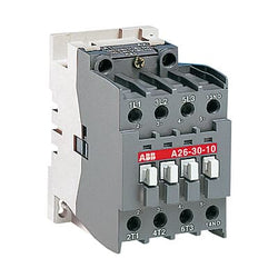
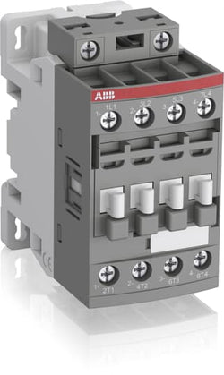
A26-30-01 220-230V 50Hz / 230-240V 60Hz Contactor.A26 contactors are mainly used for controlling 3-phase motors and generally for controlling power circuits up to 690 V AC or 220 V DC. The contactors can also be used for many other applications such as isolation, capacitor switching, lighting.

Ordering
1 piece
85364900
Popular Downloads
Dimensions
70 mm
113.5 mm
125.5 mm
1.16 kg
Technical
2
2
0
0
4P
IEC/EN 60947-1, IEC/EN 60947-4-1, UL 60335-2-40 LZGH2 A2L, UL 60947-1, UL 60947-4-1, CSA C22.2 No. 60335-2-40 LZGH2 A2L, CSA C22.2 No. 60947-1:22, CSA C22.2 No. 60947-4-1:22
Main Circuit 690 V
Control Circuit 50 / 60 Hz
Main Circuit 50 / 60 Hz
Control Circuit 50 / 60 Hz
Main Circuit 50 / 60 Hz
acc. to IEC 60947-4-1, Open Contactors Θ = 40 °C 105 A
(690 V) 40 °C 70 A
(690 V) 60 °C 60 A
(690 V) 70 °C 50 A
(690 V) 40 °C 70 A
(690 V) 60 °C 60 A
(690 V) 70 °C 50 A
(415 V) 60 °C 40 A
(440 V) 60 °C 40 A
(500 V) 60 °C 35 A
(690 V) 60 °C 25 A
(380 / 400 V) 60 °C 40 A
(220 / 230 / 240 V) 60 °C 40 A
(415 V) 60 °C 40 A
(440 V) 60 °C 40 A
(500 V) 60 °C 35 A
(690 V) 60 °C 25 A
(380 / 400 V) 60 °C 40 A
(220 / 230 / 240 V) 60 °C 40 A
(415 V) 22 kW
(440 V) 22 kW
(500 V) 22 kW
(690 V) 22 kW
(380 / 400 V) 18.5 kW
(220 / 230 / 240 V) 11 kW
(415 V) 22 kW
(440 V) 22 kW
(500 V) 22 kW
(690 V) 22 kW
(380 / 400 V) 18.5 kW
(220 / 230 / 240 V) 11 kW
at 40 °C Ambient Temp, in Free Air, from a Cold State 10 s 600 A
at 40 °C Ambient Temp, in Free Air, from a Cold State 15 min 110 A
at 40 °C Ambient Temp, in Free Air, from a Cold State 1 min 250 A
at 40 °C Ambient Temp, in Free Air, from a Cold State 1 s 1000 A
at 40 °C Ambient Temp, in Free Air, from a Cold State 30 s 350 A
cos phi=0.45 (cos phi=0.35 for Ie > 100 A) at 440 V 950 A
cos phi=0.45 (cos phi=0.35 for Ie > 100 A) at 690 V 600 A
cos phi=0.45 (cos phi=0.35 for Ie > 100 A) at 440 V 950 A
cos phi=0.45 (cos phi=0.35 for Ie > 100 A) at 690 V 600 A
acc. to IEC 60947-4-1 690 V
acc. to UL/CSA 600 V
acc. to IEC 60947-4-1 690 V
acc. to UL/CSA 600 V
6 kV
(AC-1) 600 cycles per hour
3600 cycles per hour
50 Hz 100 ... 250 V
60 Hz 100 ... 250 V
DC Operation 100 ... 250 V
50 Hz 100 ... 250 V
60 Hz 100 ... 250 V
DC Operation 100 ... 250 V
Average Holding Value 50 / 60 Hz 4 V·A
Average Holding Value 50 Hz 4 V·A
Average Holding Value 60 Hz 4 V·A
Average Holding Value DC 2 W
Average Holding Value, from Warm State 2 W
Average Holding Value 50 / 60 Hz 4 V·A
Average Holding Value 50 Hz 4 V·A
Average Holding Value 60 Hz 4 V·A
Average Holding Value DC 2 W
Average Holding Value, from Warm State 2 W
at Rated Operating Conditions AC-1 per Pole 3 W
at Rated Operating Conditions AC-3 per Pole 1 W
at Rated Operating Conditions AC-1 per Pole 3 W
at Rated Operating Conditions AC-3 per Pole 1 W
TH35-15 (35 x 15 mm Mounting Rail) acc. to IEC 60715
2 x M4 or 2 x M6 Screws Placed Diagonally
Flexible with Ferrule 1/2x 4 ... 35 mm²
Flexible with Insulated Ferrule 1/2x 4 ... 35 mm²
Rigid Stranded 1/2x 6 ... 35 mm²
Flexible with Ferrule 1/2x 4 ... 35 mm²
Flexible with Insulated Ferrule 1/2x 4 ... 35 mm²
Rigid Stranded 1/2x 6 ... 35 mm²
Flexible with Ferrule 1/2x 0.75 ... 2.5 mm²
Flexible with Insulated Ferrule 1x 0.75 ... 2.5 mm²
Flexible with Insulated Ferrule 2x 0.75 ... 1.5 mm²
Rigid Solid 1/2x 1 ... 2.5 mm²
Rigid Stranded 1/2x 1 ... 2.5 mm²
Flexible with Ferrule 1/2x 0.75 ... 2.5 mm²
Flexible with Insulated Ferrule 1x 0.75 ... 2.5 mm²
Flexible with Insulated Ferrule 2x 0.75 ... 1.5 mm²
Rigid Solid 1/2x 1 ... 2.5 mm²
Rigid Stranded 1/2x 1 ... 2.5 mm²
Control Circuit 10 mm
Main Circuit 16 mm
Control Circuit 10 mm
Main Circuit 16 mm
acc. to IEC 60529, IEC 60947-1, EN 60529 Coil Terminals IP20
acc. to IEC 60529, IEC 60947-1, EN 60529 Main Terminals IP10
acc. to IEC 60529, IEC 60947-1, EN 60529 Coil Terminals IP20
acc. to IEC 60529, IEC 60947-1, EN 60529 Main Terminals IP10
Pozidriv PZ
Control Circuit 1.2 N·m
Main Circuit 4 N·m
Control Circuit 1.2 N·m
Main Circuit 4 N·m
Screw Terminals
Block Contactor
Technical UL/CSA
Main Circuit 600 V
(600 V AC) 60 A
Rigid Stranded 1/2x 10-2 AWG
Rigid Solid 1/2x 18-14 AWG
Rigid Stranded 1/2x 18-14 AWG
Rigid Solid 1/2x 18-14 AWG
Rigid Stranded 1/2x 18-14 AWG
Control Circuit 11 in·lb
Main Circuit 35 in·lb
Control Circuit 11 in·lb
Main Circuit 35 in·lb
(120 V AC) Single Phase 3 A
(200 ... 208 V AC) Three Phase 10 A
(220 ... 240 V AC) Three Phase 15 A
(240 V AC) Single Phase 7-1/2 A
(440 ... 480 V AC) Three Phase 30 A
(550 ... 600 V AC) Three Phase 40 A
(120 V AC) Single Phase 3 A
(200 ... 208 V AC) Three Phase 10 A
(220 ... 240 V AC) Three Phase 15 A
(240 V AC) Single Phase 7-1/2 A
(440 ... 480 V AC) Three Phase 30 A
(550 ... 600 V AC) Three Phase 40 A
Environmental
Close to Contactor for Storage -60 ... +80 °C
Near Contactor for Operation in Free Air -40 ... 70 °C
Close to Contactor for Storage -60 ... +80 °C
Near Contactor for Operation in Free Air -40 ... 70 °C
Category B according to IEC 60947-1 Annex Q
Without Derating 3000 m
3g Closed Position & 2g Open Position 5 ... 300 Hz
3
Material Compliance
Following EU Directive 2011/65/EU and Amendment 2015/863 July 22, 2019
99ad8fdc-c554-4c9c-a0d9-8dbed5bad1b6 France
5dcd19ad-9fcc-445d-8f3a-f2d82860b25d Belgium
ca97187b-0d06-4656-83bb-385f9f963263 France
2d4b6723-dc39-45fc-9df8-5992e1d48cc1 Sweden
b89d5c27-b692-43a6-86a5-541bd12d966e Germany
68dbe8ea-1eea-484b-a4ef-f61273884248 Denmark
c4d706a0-4ce0-4fb3-b5e5-b3343ec72386 Germany
25a8842c-ac85-40ac-8167-165bfec13516 Croatia
48a4875a-ca87-4554-8082-cb714198b315 Czech Republic
6b97371c-f51b-4065-91a1-5040a08c81c8 Poland
b2579274-c0be-47b8-9c5f-4f3e7a1b5735 Netherlands
1b8fe42a-586e-4d23-b728-022b3a1f2852 Sweden
266f62cd-add5-4ec4-8418-019de1aa26f5 Poland
ef7d119d-3f41-452a-a51b-ae5aea250d74 Italy
efb6b6df-005c-4681-b94c-7f2b2713687e Germany
15f1d7c9-3299-4765-88fe-0f63b464c5a1 Estonia
7eaac2e9-553f-4390-92e1-509f0e37af45 Greece
36adada1-b755-413a-b9be-15fbbb224135 Portugal
0ac964e7-e14e-4f89-ad9f-cd0b99e773ba Bulgaria
78644ae4-d64c-43dc-8a85-372341704998 Poland
8c31cdea-4ce8-4ea6-8a6f-71350a0d5e79 Finland
a65d5501-7964-47cc-82c6-f4a96f3f369a Hungary
ccec6a62-82f1-4cf8-b98d-143022e3fc49 Norway
9d90c850-74e9-4bdc-bf6e-9927b3c7b430 Germany
dbe08d85-6d2d-438d-82e6-c8b8a0276292 Germany
fa56a79c-a791-4883-908b-114b3e89bf7b Hungary
64c43858-445d-4bf8-a7ba-964d89c965f4 Spain
df69f366-0123-4b21-b7e6-4fca983d99c2 Belgium
5dcd19ad-9fcc-445d-8f3a-f2d82860b25d Belgium
ca97187b-0d06-4656-83bb-385f9f963263 France
2d4b6723-dc39-45fc-9df8-5992e1d48cc1 Sweden
b89d5c27-b692-43a6-86a5-541bd12d966e Germany
68dbe8ea-1eea-484b-a4ef-f61273884248 Denmark
c4d706a0-4ce0-4fb3-b5e5-b3343ec72386 Germany
25a8842c-ac85-40ac-8167-165bfec13516 Croatia
48a4875a-ca87-4554-8082-cb714198b315 Czech Republic
6b97371c-f51b-4065-91a1-5040a08c81c8 Poland
b2579274-c0be-47b8-9c5f-4f3e7a1b5735 Netherlands
Business To Business
5. Small Equipment (No External Dimension More Than 50 cm)
ABB EcoSolutions
Yes
FSC Recycled Paper - 94.6 %
Recycled Metal - 28.2 %
Certificates and Declarations
Container Information
box 1 piece
150 mm
150 mm
103 mm
1.27 kg
3471523133839
box 8 piece
250 mm
300 mm
300 mm
10.16 kg
External Classifications and Standards
Q
EC000066 - Power contactor, AC switching
EC000066 - Power contactor, AC switching
EC000066 - Power contactor, AC switching
V11.0 : 27371003
39121529
4758 >> Iec Contactors
3707555
3210307

AL26-40-00 12V DC Contactor
Ordering
1 piece
85364900
Popular Downloads
Dimensions
45 mm
119.5 mm
86 mm
0.36 kg
Technical
3
0
2
2
3P
IEC/EN 60947-1, IEC/EN 60947-4-1, UL 60335-2-40 LZGH2 A2L, UL 60947-4-1, CSA C22.2 No. 60335-2-40 LZGH2 A2L, CSA C22.2 No. 60947-4-1
Auxiliary Circuit 690 V
Main Circuit 690 V
Auxiliary Circuit 690 V
Main Circuit 690 V
Auxiliary Circuit 50 / 60 Hz
Control Circuit 50 / 60 Hz
Main Circuit 50 / 60 Hz
Auxiliary Circuit 50 / 60 Hz
Control Circuit 50 / 60 Hz
Main Circuit 50 / 60 Hz
acc. to IEC 60947-4-1, Open Contactors Θ = 40 °C 50 A
acc. to IEC 60947-5-1, Θ = 40 °C 16 A
acc. to IEC 60947-4-1, Open Contactors Θ = 40 °C 50 A
acc. to IEC 60947-5-1, Θ = 40 °C 16 A
(690 V) 40 °C 50 A
(690 V) 60 °C 42 A
(690 V) 70 °C 37 A
(690 V) 40 °C 50 A
(690 V) 60 °C 42 A
(690 V) 70 °C 37 A
(415 V) 60 °C 32 A
(440 V) 60 °C 32 A
(500 V) 60 °C 28 A
(690 V) 60 °C 21 A
(380 / 400 V) 60 °C 32 A
(220 / 230 / 240 V) 60 °C 33 A
(415 V) 60 °C 32 A
(440 V) 60 °C 32 A
(500 V) 60 °C 28 A
(690 V) 60 °C 21 A
(380 / 400 V) 60 °C 32 A
(220 / 230 / 240 V) 60 °C 33 A
(415 V) 60 °C 32 A
(440 V) 60 °C 32 A
(500 V) 60 °C 28 A
(690 V) 60 °C 21 A
(380 / 400 V) 60 °C 32 A
(220 / 230 / 240 V) 60 °C 33 A
(415 V) 60 °C 32 A
(440 V) 60 °C 32 A
(500 V) 60 °C 28 A
(690 V) 60 °C 21 A
(380 / 400 V) 60 °C 32 A
(220 / 230 / 240 V) 60 °C 33 A
(500 V) 2 A
(690 V) 2 A
(24 / 127 V) 6 A
(220 / 240 V) 4 A
(400 / 440 V) 3 A
(500 V) 2 A
(690 V) 2 A
(24 / 127 V) 6 A
(220 / 240 V) 4 A
(400 / 440 V) 3 A
(110 V) 2 Poles in Series, 40 °C 50 A
(110 V) 2 Poles in Series, 60 °C 42 A
(110 V) 2 Poles in Series, 70 °C 37 A
(110 V) 3 Poles in Series, 40 °C 50 A
(110 V) 3 Poles in Series, 60 °C 42 A
(110 V) 3 Poles in Series, 70 °C 37 A
(220 V) 3 Poles in Series, 40 °C 50 A
(220 V) 3 Poles in Series, 60 °C 42 A
(220 V) 3 Poles in Series, 70 °C 37 A
(72 V) 1-Pole, 40 °C 50 A
(72 V) 1-Pole, 60 °C 42 A
(72 V) 1-Pole, 70 °C 37 A
(72 V) 2 Poles in Series, 40 °C 50 A
(72 V) 2 Poles in Series, 60 °C 42 A
(72 V) 2 Poles in Series, 70 °C 37 A
(72 V) 3 Poles in Series, 40 °C 50 A
(72 V) 3 Poles in Series, 60 °C 42 A
(72 V) 3 Poles in Series, 70 °C 37 A
(110 V) 2 Poles in Series, 40 °C 50 A
(110 V) 2 Poles in Series, 60 °C 42 A
(110 V) 2 Poles in Series, 70 °C 37 A
(110 V) 3 Poles in Series, 40 °C 50 A
(110 V) 3 Poles in Series, 60 °C 42 A
(110 V) 3 Poles in Series, 70 °C 37 A
(220 V) 3 Poles in Series, 40 °C 50 A
(220 V) 3 Poles in Series, 60 °C 42 A
(220 V) 3 Poles in Series, 70 °C 37 A
(72 V) 1-Pole, 40 °C 50 A
(72 V) 1-Pole, 60 °C 42 A
(72 V) 1-Pole, 70 °C 37 A
(72 V) 2 Poles in Series, 40 °C 50 A
(72 V) 2 Poles in Series, 60 °C 42 A
(72 V) 2 Poles in Series, 70 °C 37 A
(72 V) 3 Poles in Series, 40 °C 50 A
(72 V) 3 Poles in Series, 60 °C 42 A
(72 V) 3 Poles in Series, 70 °C 37 A
(110 V) 2 Poles in Series, 40 °C 50 A
(110 V) 2 Poles in Series, 60 °C 42 A
(110 V) 2 Poles in Series, 70 °C 37 A
(110 V) 3 Poles in Series, 40 °C 50 A
(110 V) 3 Poles in Series, 60 °C 42 A
(110 V) 3 Poles in Series, 70 °C 37 A
(220 V) 3 Poles in Series, 40 °C 50 A
(220 V) 3 Poles in Series, 60 °C 42 A
(220 V) 3 Poles in Series, 70 °C 37 A
(72 V) 1-Pole, 40 °C 50 A
(110 V) 2 Poles in Series, 40 °C 50 A
(110 V) 2 Poles in Series, 60 °C 42 A
(110 V) 2 Poles in Series, 70 °C 37 A
(110 V) 3 Poles in Series, 40 °C 50 A
(110 V) 3 Poles in Series, 60 °C 42 A
(110 V) 3 Poles in Series, 70 °C 37 A
(220 V) 3 Poles in Series, 40 °C 25 A
(220 V) 3 Poles in Series, 60 °C 25 A
(220 V) 3 Poles in Series, 70 °C 25 A
(72 V) 1-Pole, 40 °C 25 A
(72 V) 1-Pole, 60 °C 25 A
(72 V) 1-Pole, 70 °C 25 A
(72 V) 2 Poles in Series, 40 °C 50 A
(72 V) 2 Poles in Series, 60 °C 42 A
(72 V) 2 Poles in Series, 70 °C 37 A
(72 V) 3 Poles in Series, 40 °C 50 A
(72 V) 3 Poles in Series, 60 °C 42 A
(72 V) 3 Poles in Series, 70 °C 37 A
(110 V) 2 Poles in Series, 40 °C 50 A
(110 V) 2 Poles in Series, 60 °C 42 A
(110 V) 2 Poles in Series, 70 °C 37 A
(110 V) 3 Poles in Series, 40 °C 50 A
(110 V) 3 Poles in Series, 60 °C 42 A
(110 V) 3 Poles in Series, 70 °C 37 A
(220 V) 3 Poles in Series, 40 °C 25 A
(220 V) 3 Poles in Series, 60 °C 25 A
(220 V) 3 Poles in Series, 70 °C 25 A
(72 V) 1-Pole, 40 °C 25 A
(24 V) 6 A / 144 W
(48 V) 2.8 A / 134 W
(72 V) 1 A / 72 W
(110 V) 0.55 A / 60 W
(125 V) 0.55 A / 69 W
(220 V) 0.27 A / 60 W
(250 V) 0.27 A / 68 W
(400 V) 0.15 A / 60 W
(500 V) 0.13 A / 65 W
(600 V) 0.1 A / 60 W
(24 V) 6 A / 144 W
(48 V) 2.8 A / 134 W
(72 V) 1 A / 72 W
(110 V) 0.55 A / 60 W
(125 V) 0.55 A / 69 W
(220 V) 0.27 A / 60 W
(250 V) 0.27 A / 68 W
(400 V) 0.15 A / 60 W
(500 V) 0.13 A / 65 W
(600 V) 0.1 A / 60 W
(400 V) 15 kW
(415 V) 15 kW
(440 V) 18.5 kW
(500 V) 18.5 kW
(690 V) 18.5 kW
(380 / 400 V) 15 kW
(220 / 230 / 240 V) 9 kW
(400 V) 15 kW
(415 V) 15 kW
(440 V) 18.5 kW
(500 V) 18.5 kW
(690 V) 18.5 kW
(380 / 400 V) 15 kW
(220 / 230 / 240 V) 9 kW
(415 V) 15 kW
(440 V) 18.5 kW
(500 V) 18.5 kW
(690 V) 18.5 kW
(380 / 400 V) 15 kW
(220 / 230 / 240 V) 9 kW
(415 V) 15 kW
(440 V) 18.5 kW
(500 V) 18.5 kW
(690 V) 18.5 kW
(380 / 400 V) 15 kW
(220 / 230 / 240 V) 9 kW
at 40 °C Ambient Temp, in Free Air, from a Cold State 10 s 350 A
at 40 °C Ambient Temp, in Free Air, from a Cold State 15 min 50 A
at 40 °C Ambient Temp, in Free Air, from a Cold State 1 min 150 A
at 40 °C Ambient Temp, in Free Air, from a Cold State 1 s 700 A
at 40 °C Ambient Temp, in Free Air, from a Cold State 30 s 225 A
for 0.1 s 140 A
for 1 s 100 A
cos phi=0.45 (cos phi=0.35 for Ie > 100 A) at 440 V 500 A
cos phi=0.45 (cos phi=0.35 for Ie > 100 A) at 690 V 200 A
cos phi=0.45 (cos phi=0.35 for Ie > 100 A) at 440 V 500 A
cos phi=0.45 (cos phi=0.35 for Ie > 100 A) at 690 V 200 A
acc. to IEC 60947-4-1 690 V
acc. to IEC 60947-5-1 690 V
acc. to UL/CSA 600 V
acc. to IEC 60947-4-1 690 V
acc. to IEC 60947-5-1 690 V
acc. to UL/CSA 600 V
6 kV
(AC-1) 600 cycles per hour
(AC-15) 1200 cycles per hour
(AC-2 / AC-4) 150 cycles per hour
(AC-3) 1200 cycles per hour
(DC-13) 900 cycles per hour
(AC-1) 600 cycles per hour
(AC-15) 1200 cycles per hour
(AC-2 / AC-4) 150 cycles per hour
(AC-3) 1200 cycles per hour
(DC-13) 900 cycles per hour
3600 cycles per hour
50 Hz 24 ... 60 V
60 Hz 24 ... 60 V
DC Operation 20 ... 60 V
50 Hz 24 ... 60 V
60 Hz 24 ... 60 V
DC Operation 20 ... 60 V
at 6 A per Pole 0.1 W
at Rated Operating Conditions AC-1 per Pole 2.4 W
at Rated Operating Conditions AC-3 per Pole 0.9 W
at 6 A per Pole 0.1 W
at Rated Operating Conditions AC-1 per Pole 2.4 W
at Rated Operating Conditions AC-3 per Pole 0.9 W
Between Coil De-energization and NC Contact Closing 13 ... 98 ms
Between Coil De-energization and NO Contact Opening 11 ... 95 ms
Between Coil Energization and NC Contact Opening 38 ... 90 ms
Between Coil Energization and NO Contact Closing 40 ... 95 ms
Between Coil De-energization and NC Contact Closing 13 ... 98 ms
Between Coil De-energization and NO Contact Opening 11 ... 95 ms
Between Coil Energization and NC Contact Opening 38 ... 90 ms
Between Coil Energization and NO Contact Closing 40 ... 95 ms
TH35-15 (35 x 15 mm Mounting Rail) acc. to IEC 60715
TH35-7.5 (35 x 7.5 mm Mounting Rail) acc. to IEC 60715
TH35-15 (35 x 15 mm Mounting Rail) acc. to IEC 60715
TH35-7.5 (35 x 7.5 mm Mounting Rail) acc. to IEC 60715
2 x M4 Screws Placed Diagonally
Flexible with Ferrule 1/2x 1.5 ... 10 mm²
Flexible with Insulated Ferrule 1x 1.5 ... 10 mm²
Flexible with Insulated Ferrule 2x 1.5 ... 4 mm²
Rigid Solid 1/2x 2.5 ... 4 mm²
Rigid Stranded 1/2x 2.5 ... 10 mm²
Flexible with Ferrule 1/2x 1.5 ... 10 mm²
Flexible with Insulated Ferrule 1x 1.5 ... 10 mm²
Flexible with Insulated Ferrule 2x 1.5 ... 4 mm²
Rigid Solid 1/2x 2.5 ... 4 mm²
Rigid Stranded 1/2x 2.5 ... 10 mm²
Flexible with Ferrule 1/2x 0.75 ... 2.5 mm²
Flexible with Insulated Ferrule 1x 0.75 ... 2.5 mm²
Flexible with Insulated Ferrule 2x 0.75 ... 1.5 mm²
Rigid Solid 1/2x 1 ... 2.5 mm²
Rigid Stranded 1/2x 1 ... 2.5 mm²
Flexible with Ferrule 1/2x 0.75 ... 2.5 mm²
Flexible with Insulated Ferrule 1x 0.75 ... 2.5 mm²
Flexible with Insulated Ferrule 2x 0.75 ... 1.5 mm²
Rigid Solid 1/2x 1 ... 2.5 mm²
Rigid Stranded 1/2x 1 ... 2.5 mm²
Flexible with Ferrule 1/2x 0.75 ... 2.5 mm²
Flexible with Insulated Ferrule 1x 0.75 ... 2.5 mm²
Flexible with Insulated Ferrule 2x 0.75 ... 1.5 mm²
Rigid Solid 1/2x 1 ... 2.5 mm²
Rigid Stranded 1/2x 1 ... 2.5 mm²
Flexible with Ferrule 1/2x 0.75 ... 2.5 mm²
Flexible with Insulated Ferrule 1x 0.75 ... 2.5 mm²
Flexible with Insulated Ferrule 2x 0.75 ... 1.5 mm²
Rigid Solid 1/2x 1 ... 2.5 mm²
Rigid Stranded 1/2x 1 ... 2.5 mm²
Auxiliary Circuit 10 mm
Control Circuit 10 mm
Main Circuit 14 mm
Auxiliary Circuit 10 mm
Control Circuit 10 mm
Main Circuit 14 mm
acc. to IEC 60529, IEC 60947-1, EN 60529 Auxiliary Terminals IP20
acc. to IEC 60529, IEC 60947-1, EN 60529 Coil Terminals IP20
acc. to IEC 60529, IEC 60947-1, EN 60529 Main Terminals IP20
acc. to IEC 60529, IEC 60947-1, EN 60529 Auxiliary Terminals IP20
acc. to IEC 60529, IEC 60947-1, EN 60529 Coil Terminals IP20
acc. to IEC 60529, IEC 60947-1, EN 60529 Main Terminals IP20
Auxiliary Circuit 1.2 N·m
Control Circuit 1.2 N·m
Main Circuit 2.5 N·m
Auxiliary Circuit 1.2 N·m
Control Circuit 1.2 N·m
Main Circuit 2.5 N·m
Screw Terminals
Block Contactor
Technical UL/CSA
Main Circuit 600 V
(600 V AC) 50 A
(120 V AC) Single Phase 2 hp
(200 ... 208 V AC) Three Phase 10 hp
(220 ... 240 V AC) Three Phase 10 hp
(240 V AC) Single Phase 5 hp
(440 ... 480 V AC) Three Phase 20 hp
(550 ... 600 V AC) Three Phase 25 hp
(120 V AC) Single Phase 2 hp
(200 ... 208 V AC) Three Phase 10 hp
(220 ... 240 V AC) Three Phase 10 hp
(240 V AC) Single Phase 5 hp
(440 ... 480 V AC) Three Phase 20 hp
(550 ... 600 V AC) Three Phase 25 hp
Rigid Solid 1/2x 14-10 AWG
Rigid Stranded 1/2x 14-8 AWG
Rigid Solid 1/2x 14-10 AWG
Rigid Stranded 1/2x 14-8 AWG
Rigid Solid 1/2x 18-14 AWG
Rigid Stranded 1/2x 18-14 AWG
Rigid Solid 1/2x 18-14 AWG
Rigid Stranded 1/2x 18-14 AWG
Rigid Solid 1/2x 18-14 AWG
Rigid Stranded 1/2x 18-14 AWG
Rigid Solid 1/2x 18-14 AWG
Rigid Stranded 1/2x 18-14 AWG
Auxiliary Circuit 11 in·lb
Control Circuit 11 in·lb
Main Circuit 22 in·lb
Auxiliary Circuit 11 in·lb
Control Circuit 11 in·lb
Main Circuit 22 in·lb
(120 V AC) Single Phase 24 A
(200 ... 208 V AC) Three Phase 32.2 A
(220 ... 240 V AC) Three Phase 28 A
(240 V AC) Single Phase 28 A
(440 ... 480 V AC) Three Phase 27 A
(550 ... 600 V AC) Three Phase 27 A
(120 V AC) Single Phase 24 A
(200 ... 208 V AC) Three Phase 32.2 A
(220 ... 240 V AC) Three Phase 28 A
(240 V AC) Single Phase 28 A
(440 ... 480 V AC) Three Phase 27 A
(550 ... 600 V AC) Three Phase 27 A
Environmental
Close to Contactor Fitted with Thermal O/L Relay -25 ... 60 °C
Close to Contactor without Thermal O/L Relay -40 ... 70 °C
Close to Contactor for Storage -60 ... +80 °C
Close to Contactor Fitted with Thermal O/L Relay -25 ... 60 °C
Close to Contactor without Thermal O/L Relay -40 ... 70 °C
Close to Contactor for Storage -60 ... +80 °C
acc. to IEC 60068-2-30 and 60068-2-11 - UTE C 63-100 specification II
Without Derating 3000 m
Closed, Shock Direction: A 30 g
Closed, Shock Direction: B1 25 g
Closed, Shock Direction: B2 15 g
Closed, Shock Direction: C1 25 g
Closed, Shock Direction: C2 25 g
Closed, Shock Direction: A 30 g
Closed, Shock Direction: B1 25 g
Closed, Shock Direction: B2 15 g
Closed, Shock Direction: C1 25 g
Closed, Shock Direction: C2 25 g
4g Closed Position & 2g Open position 5 ... 300 Hz
3
Material Compliance
Business To Business
5. Small Equipment (No External Dimension More Than 50 cm)
ABB EcoSolutions
Recycled Cardboard - 86 %
Recycled Metal - 28 %
Certificates and Declarations
Container Information
box 1 piece
87 mm
121 mm
47 mm
0.36 kg
3471523005488
box 18 piece
250 mm
300 mm
315 mm
12.96 kg
External Classifications and Standards
Q
EC000066 - Power contactor, AC switching
EC000066 - Power contactor, AC switching
EC000066 - Power contactor, AC switching
V11.0 : 27371003
39121529
4758 >> Iec Contactors
3708055
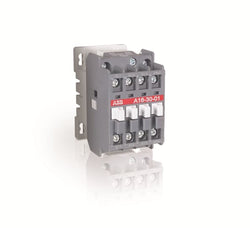
A16-30-01 400-415V 50Hz / 415-440V 60Hz Contactor

Ordering
2 piece
85363030
Popular Downloads
Dimensions
30.25 mm
32.4 mm
10.5 mm
0.015 kg
Technical
Control Circuit 50 / 60 Hz
50 Hz / 60 Hz 250 ... 440 V AC
A45
A50
A63
A75
A95
A110
GA75
UA50
UA63
UA75
UA95
UA110
UA50RA
UA63RA
UA75RA
UA95RA
UA110RA
AX50
AX65
AX80
AX95
AX115
AX150
Surge Suppressor
Environmental
Operation -20 ... +70 °C
Material Compliance
Following EU Directive 2011/65/EU and Amendment 2015/863 July 22, 2019
Business To Business
5. Small Equipment (No External Dimension More Than 50 cm)
Certificates and Declarations
Container Information
blister 2 piece
65 mm
96 mm
12 mm
0.03 kg
3471522121318
External Classifications and Standards
EC002498 - Accessories for low-voltage switch technology
EC002498 - Accessories/spare parts for low-voltage switch technology
EC002498 - Accessories/spare parts for low-voltage switch technology
V11.0 : 27371392
39121610
4906 >> Surge suppressers
Ordering
1 piece
85364900
Popular Downloads
Dimensions
45 mm
77 mm
86 mm
0.27 kg
Technical
4
0
0
0
4P
IEC/EN 60947-1, IEC/EN 60947-4-1, UL 60335-2-40 LZGH2 A2L, UL 60947-1, UL 60947-4-1, CSA C22.2 No. 60335-2-40 LZGH2 A2L, CAN/CSA C22.2 No.60947-1, CAN/CSA C22.2 No.60947-4-1
Main Circuit 690 V
Control Circuit 50 / 60 Hz
Main Circuit 50 / 60 Hz
Control Circuit 50 / 60 Hz
Main Circuit 50 / 60 Hz
acc. to IEC 60947-4-1, Open Contactors Θ = 40 °C 35 A
(690 V) 40 °C 30 A
(690 V) 60 °C 30 A
(690 V) 70 °C 26 A
(690 V) 40 °C 30 A
(690 V) 60 °C 30 A
(690 V) 70 °C 26 A
(415 V) 60 °C 18 A
(440 V) 60 °C 18 A
(500 V) 60 °C 15 A
(690 V) 60 °C 10.5 A
(380 / 400 V) 60 °C 18 A
(220 / 230 / 240 V) 60 °C 18 A
(415 V) 60 °C 18 A
(440 V) 60 °C 18 A
(500 V) 60 °C 15 A
(690 V) 60 °C 10.5 A
(380 / 400 V) 60 °C 18 A
(220 / 230 / 240 V) 60 °C 18 A
(110 V) 1-Pole, 40 °C 20 A
(110 V) 1-Pole, 60 °C 20 A
(110 V) 1-Pole, 70 °C 20 A
(110 V) 2 Poles in Series, 40 °C 30 A
(110 V) 2 Poles in Series, 60 °C 30 A
(110 V) 2 Poles in Series, 70 °C 26 A
(110 V) 3 Poles in Series, 40 °C 30 A
(110 V) 3 Poles in Series, 60 °C 30 A
(110 V) 3 Poles in Series, 70 °C 26 A
(110 V) 4 Poles in Series, 40 °C 30 A
(110 V) 4 Poles in Series, 60 °C 30 A
(110 V) 4 Poles in Series, 70 °C 26 A
(220 V) 2 Poles in Series, 40 °C 20 A
(220 V) 2 Poles in Series, 60 °C 20 A
(220 V) 2 Poles in Series, 70 °C 20 A
(220 V) 3 Poles in Series, 40 °C 30 A
(220 V) 3 Poles in Series, 60 °C 30 A
(220 V) 3 Poles in Series, 70 °C 26 A
(220 V) 4 Poles in Series, 40 °C 30 A
(220 V) 4 Poles in Series, 60 °C 30 A
(220 V) 4 Poles in Series, 70 °C 26 A
(440 V) 4 Poles in Series, 40 °C 20 A
(440 V) 4 Poles in Series, 60 °C 20 A
(440 V) 4 Poles in Series, 70 °C 20 A
(72 V) 1-Pole, 40 °C 30 A
(72 V) 1-Pole, 60 °C 30 A
(72 V) 1-Pole, 70 °C 26 A
(72 V) 2 Poles in Series, 40 °C 30 A
(72 V) 2 Poles in Series, 60 °C 30 A
(72 V) 2 Poles in Series, 70 °C 26 A
(72 V) 3 Poles in Series, 40 °C 30 A
(72 V) 3 Poles in Series, 60 °C 30 A
(72 V) 3 Poles in Series, 70 °C 26 A
(72 V) 4 Poles in Series, 40 °C 30 A
(72 V) 4 Poles in Series, 60 °C 30 A
(72 V) 4 Poles in Series, 70 °C 26 A
(110 V) 1-Pole, 40 °C 20 A
(110 V) 1-Pole, 60 °C 20 A
(110 V) 1-Pole, 70 °C 20 A
(110 V) 2 Poles in Series, 40 °C 30 A
(110 V) 2 Poles in Series, 60 °C 30 A
(110 V) 2 Poles in Series, 70 °C 26 A
(110 V) 3 Poles in Series, 40 °C 30 A
(110 V) 3 Poles in Series, 60 °C 30 A
(110 V) 3 Poles in Series, 70 °C 26 A
(110 V) 4 Poles in Series, 40 °C 30 A
(110 V) 1-Pole, 40 °C 8 A
(110 V) 1-Pole, 60 °C 8 A
(110 V) 1-Pole, 70 °C 8 A
(110 V) 2 Poles in Series, 40 °C 30 A
(110 V) 2 Poles in Series, 60 °C 30 A
(110 V) 2 Poles in Series, 70 °C 26 A
(110 V) 3 Poles in Series, 40 °C 30 A
(110 V) 3 Poles in Series, 60 °C 30 A
(110 V) 3 Poles in Series, 70 °C 26 A
(110 V) 4 Poles in Series, 40 °C 30 A
(110 V) 4 Poles in Series, 60 °C 30 A
(110 V) 4 Poles in Series, 70 °C 26 A
(220 V) 2 Poles in Series, 40 °C 8 A
(220 V) 2 Poles in Series, 60 °C 8 A
(220 V) 2 Poles in Series, 70 °C 8 A
(220 V) 3 Poles in Series, 40 °C 30 A
(220 V) 3 Poles in Series, 60 °C 30 A
(220 V) 3 Poles in Series, 70 °C 26 A
(220 V) 4 Poles in Series, 40 °C 30 A
(220 V) 4 Poles in Series, 60 °C 30 A
(220 V) 4 Poles in Series, 70 °C 26 A
(440 V) 4 Poles in Series, 40 °C 8 A
(440 V) 4 Poles in Series, 60 °C 8 A
(440 V) 4 Poles in Series, 70 °C 8 A
(72 V) 1-Pole, 40 °C 30 A
(72 V) 1-Pole, 60 °C 30 A
(72 V) 1-Pole, 70 °C 26 A
(72 V) 2 Poles in Series, 40 °C 30 A
(72 V) 2 Poles in Series, 60 °C 30 A
(72 V) 2 Poles in Series, 70 °C 26 A
(72 V) 3 Poles in Series, 40 °C 30 A
(72 V) 3 Poles in Series, 60 °C 30 A
(72 V) 3 Poles in Series, 70 °C 26 A
(72 V) 4 Poles in Series, 40 °C 30 A
(72 V) 4 Poles in Series, 60 °C 30 A
(72 V) 4 Poles in Series, 70 °C 26 A
(110 V) 1-Pole, 40 °C 8 A
(110 V) 1-Pole, 60 °C 8 A
(110 V) 1-Pole, 70 °C 8 A
(110 V) 2 Poles in Series, 40 °C 30 A
(110 V) 2 Poles in Series, 60 °C 30 A
(110 V) 2 Poles in Series, 70 °C 26 A
(110 V) 3 Poles in Series, 40 °C 30 A
(110 V) 3 Poles in Series, 60 °C 30 A
(110 V) 3 Poles in Series, 70 °C 26 A
(110 V) 4 Poles in Series, 40 °C 30 A
(110 V) 1-Pole, 40 °C 4 A
(110 V) 1-Pole, 60 °C 4 A
(110 V) 1-Pole, 70 °C 4 A
(110 V) 2 Poles in Series, 40 °C 20 A
(110 V) 2 Poles in Series, 60 °C 20 A
(110 V) 2 Poles in Series, 70 °C 20 A
(110 V) 3 Poles in Series, 40 °C 30 A
(110 V) 3 Poles in Series, 60 °C 30 A
(110 V) 3 Poles in Series, 70 °C 26 A
(110 V) 4 Poles in Series, 40 °C 30 A
(110 V) 4 Poles in Series, 60 °C 30 A
(110 V) 4 Poles in Series, 70 °C 26 A
(220 V) 2 Poles in Series, 40 °C 4 A
(220 V) 2 Poles in Series, 60 °C 4 A
(220 V) 2 Poles in Series, 70 °C 4 A
(220 V) 3 Poles in Series, 40 °C 16 A
(220 V) 3 Poles in Series, 60 °C 16 A
(220 V) 3 Poles in Series, 70 °C 16 A
(220 V) 4 Poles in Series, 40 °C 20 A
(220 V) 4 Poles in Series, 60 °C 20 A
(220 V) 4 Poles in Series, 70 °C 20 A
(440 V) 4 Poles in Series, 40 °C 4 A
(440 V) 4 Poles in Series, 60 °C 4 A
(440 V) 4 Poles in Series, 70 °C 4 A
(72 V) 1-Pole, 40 °C 16 A
(72 V) 1-Pole, 60 °C 16 A
(72 V) 1-Pole, 70 °C 16 A
(72 V) 2 Poles in Series, 40 °C 30 A
(72 V) 2 Poles in Series, 60 °C 30 A
(72 V) 2 Poles in Series, 70 °C 26 A
(72 V) 3 Poles in Series, 40 °C 30 A
(72 V) 3 Poles in Series, 60 °C 30 A
(72 V) 3 Poles in Series, 70 °C 26 A
(72 V) 4 Poles in Series, 40 °C 30 A
(72 V) 4 Poles in Series, 60 °C 30 A
(72 V) 4 Poles in Series, 70 °C 26 A
(110 V) 1-Pole, 40 °C 4 A
(110 V) 1-Pole, 60 °C 4 A
(110 V) 1-Pole, 70 °C 4 A
(110 V) 2 Poles in Series, 40 °C 20 A
(110 V) 2 Poles in Series, 60 °C 20 A
(110 V) 2 Poles in Series, 70 °C 20 A
(110 V) 3 Poles in Series, 40 °C 30 A
(110 V) 3 Poles in Series, 60 °C 30 A
(110 V) 3 Poles in Series, 70 °C 26 A
(110 V) 4 Poles in Series, 40 °C 30 A
(400 V) 7.5 kW
(415 V) 9 kW
(440 V) 9 kW
(500 V) 9 kW
(690 V) 9 kW
(380 / 400 V) 7.5 kW
(220 / 230 / 240 V) 4 kW
(400 V) 7.5 kW
(415 V) 9 kW
(440 V) 9 kW
(500 V) 9 kW
(690 V) 9 kW
(380 / 400 V) 7.5 kW
(220 / 230 / 240 V) 4 kW
at 40 °C Ambient Temp, in Free Air, from a Cold State 10 s 150 A
at 40 °C Ambient Temp, in Free Air, from a Cold State 15 min 35 A
at 40 °C Ambient Temp, in Free Air, from a Cold State 1 min 60 A
at 40 °C Ambient Temp, in Free Air, from a Cold State 1 s 300 A
at 40 °C Ambient Temp, in Free Air, from a Cold State 30 s 80 A
cos phi=0.45 (cos phi=0.35 for Ie > 100 A) at 440 V 250 A
cos phi=0.45 (cos phi=0.35 for Ie > 100 A) at 690 V 106 A
cos phi=0.45 (cos phi=0.35 for Ie > 100 A) at 440 V 250 A
cos phi=0.45 (cos phi=0.35 for Ie > 100 A) at 690 V 106 A
acc. to IEC 60947-4-1 690 V
acc. to UL/CSA 600 V
acc. to IEC 60947-4-1 690 V
acc. to UL/CSA 600 V
6 kV
(AC-1) 600 cycles per hour
3600 cycles per hour
50 Hz 100 ... 250 V
60 Hz 100 ... 250 V
DC Operation 100 ... 250 V
50 Hz 100 ... 250 V
60 Hz 100 ... 250 V
DC Operation 100 ... 250 V
at Rated Operating Conditions AC-1 per Pole 1.2 W
at Rated Operating Conditions AC-3 per Pole 0.35 W
at Rated Operating Conditions AC-1 per Pole 1.2 W
at Rated Operating Conditions AC-3 per Pole 0.35 W
Between Coil De-energization and NC Contact Closing 13 ... 98 ms
Between Coil De-energization and NO Contact Opening 11 ... 95 ms
Between Coil Energization and NC Contact Opening 38 ... 90 ms
Between Coil Energization and NO Contact Closing 40 ... 95 ms
Between Coil De-energization and NC Contact Closing 13 ... 98 ms
Between Coil De-energization and NO Contact Opening 11 ... 95 ms
Between Coil Energization and NC Contact Opening 38 ... 90 ms
Between Coil Energization and NO Contact Closing 40 ... 95 ms
TH35-15 (35 x 15 mm Mounting Rail) acc. to IEC 60715
TH35-7.5 (35 x 7.5 mm Mounting Rail) acc. to IEC 60715
TH35-15 (35 x 15 mm Mounting Rail) acc. to IEC 60715
TH35-7.5 (35 x 7.5 mm Mounting Rail) acc. to IEC 60715
2 x M4 Screws Placed Diagonally
Flexible with Ferrule 1/2x 0.75 ... 6 mm²
Flexible with Insulated Ferrule 1x 0.75 ... 4 mm²
Flexible with Insulated Ferrule 2x 0.75 ... 2.5 mm²
Rigid Solid 1/2x 1 ... 4 mm²
Rigid Stranded 1/2x 1 ... 6 mm²
Flexible with Ferrule 1/2x 0.75 ... 6 mm²
Flexible with Insulated Ferrule 1x 0.75 ... 4 mm²
Flexible with Insulated Ferrule 2x 0.75 ... 2.5 mm²
Rigid Solid 1/2x 1 ... 4 mm²
Rigid Stranded 1/2x 1 ... 6 mm²
Rigid Solid 1/2x 1 ... 2.5 mm²
Rigid Stranded 1/2x 1 ... 2.5 mm²
Rigid Solid 1/2x 1 ... 2.5 mm²
Rigid Stranded 1/2x 1 ... 2.5 mm²
Flexible with Ferrule 1/2x 0.75 ... 2.5 mm²
Flexible with Insulated Ferrule 1x 0.75 ... 2.5 mm²
Flexible with Insulated Ferrule 2x 0.75 ... 1.5 mm²
Rigid Solid 1/2x 1 ... 2.5 mm²
Rigid Stranded 1/2x 1 ... 2.5 mm²
Flexible with Ferrule 1/2x 0.75 ... 2.5 mm²
Flexible with Insulated Ferrule 1x 0.75 ... 2.5 mm²
Flexible with Insulated Ferrule 2x 0.75 ... 1.5 mm²
Rigid Solid 1/2x 1 ... 2.5 mm²
Rigid Stranded 1/2x 1 ... 2.5 mm²
Control Circuit 10 mm
Main Circuit 10 mm
Control Circuit 10 mm
Main Circuit 10 mm
acc. to IEC 60529, IEC 60947-1, EN 60529 Coil Terminals IP20
acc. to IEC 60529, IEC 60947-1, EN 60529 Main Terminals IP20
acc. to IEC 60529, IEC 60947-1, EN 60529 Coil Terminals IP20
acc. to IEC 60529, IEC 60947-1, EN 60529 Main Terminals IP20
Control Circuit 1.2 N·m
Main Circuit 1.5 N·m
Control Circuit 1.2 N·m
Main Circuit 1.5 N·m
Screw Terminals
Block Contactor
Technical UL/CSA
Main Circuit 600 V
(600 V AC) 30 A
Rigid Solid 1/2x 16-10 AWG
Rigid Stranded 1/2x 16-10 AWG
Rigid Solid 1/2x 16-10 AWG
Rigid Stranded 1/2x 16-10 AWG
Rigid Solid 1/2x 18-14 AWG
Rigid Stranded 1/2x 18-14 AWG
Rigid Solid 1/2x 18-14 AWG
Rigid Stranded 1/2x 18-14 AWG
Rigid Solid 1/2x 18-14 AWG
Rigid Stranded 1/2x 18-14 AWG
Rigid Solid 1/2x 18-14 AWG
Rigid Stranded 1/2x 18-14 AWG
Control Circuit 11 in·lb
Main Circuit 13 in·lb
Control Circuit 11 in·lb
Main Circuit 13 in·lb
Environmental
Close to Contactor for Storage -60 ... +80 °C
Near Contactor for Operation in Free Air -40 ... 70 °C
Close to Contactor for Storage -60 ... +80 °C
Near Contactor for Operation in Free Air -40 ... 70 °C
Category B according to IEC 60947-1 Annex Q
Without Derating 3000 m
Closed, Shock Direction: B1 25 g
Open, Shock Direction: B1 5 g
Shock Direction: A 30 g
Shock Direction: B2 15 g
Shock Direction: C1 25 g
Shock Direction: C2 25 g
Closed, Shock Direction: B1 25 g
Open, Shock Direction: B1 5 g
Shock Direction: A 30 g
Shock Direction: B2 15 g
Shock Direction: C1 25 g
Shock Direction: C2 25 g
4g Closed Position & 2g Open position 5 ... 300 Hz
3
Material Compliance
Following EU Directive 2011/65/EU and Amendment 2015/863 July 22, 2019
1132bd74-ed5b-46bc-b08f-af96fe74f6c0 China
f674eaea-b0bc-4f32-acbc-52f37768c00b Croatia
41924d84-57c6-47d2-b726-750ae763f396 Czech Republic
285679a7-b83f-4270-9664-b65098857652 Poland
a411e24b-6f36-418e-941e-3bed24629158 Sweden
8b61f352-d50b-45ef-a924-29b15029b821 Germany
c45ff246-79f0-4d50-9882-8e0cbef9402e Germany
839b82fb-cd06-4439-8468-d41f7f398421 France
202adc67-af08-41d6-8e13-4acbade49d51 France
16aa7940-8b32-48e2-a994-d1706e9f8702 Germany
804bf104-b89c-4b25-9444-a587ac11e883 Sweden
b55d7d8d-1a84-4f96-9827-4de958752808 Germany
4f1b1d54-9788-4008-bc09-ec73b4c9f9b6 Denmark
26f9d551-0ab3-4f57-9851-e343da6abe84 Portugal
1ccbb590-d927-4a27-a631-39ef60434875 Belgium
1c1e6e9b-7b99-4ecb-b862-2d90345afdc2 Bulgaria
cc084472-866c-4bda-b790-2f3ace002457 Greece
0c2a1ac8-a1f0-438e-93ca-f0fb3eea4502 Spain
ab964a23-2e12-4f23-8690-95746a2274d4 Netherlands
db11d5b0-ecbc-4244-b358-d217429e0902 Finland
36274f98-a69b-4acf-a00d-b17e243782c0 Estonia
d48ef082-1db0-4ce9-8c7f-c13bc9d0ccdd Hungary
82634a2a-f9c5-417e-b07f-369f9c5fd8fb Norway
2dba9c0f-9fdf-4b0b-bdee-ba69545861f2 Poland
f7031ab7-16d6-402a-83d5-cf75529eee7d Germany
fc5125a4-2b85-41fc-9354-e241f4825164 Poland
16f761ab-774c-4e1f-8fa9-7e485ff1de65 Hungary
495a77dc-9fa7-4b77-a900-075d090baad5 Belgium
f674eaea-b0bc-4f32-acbc-52f37768c00b Croatia
41924d84-57c6-47d2-b726-750ae763f396 Czech Republic
285679a7-b83f-4270-9664-b65098857652 Poland
a411e24b-6f36-418e-941e-3bed24629158 Sweden
8b61f352-d50b-45ef-a924-29b15029b821 Germany
c45ff246-79f0-4d50-9882-8e0cbef9402e Germany
839b82fb-cd06-4439-8468-d41f7f398421 France
202adc67-af08-41d6-8e13-4acbade49d51 France
16aa7940-8b32-48e2-a994-d1706e9f8702 Germany
804bf104-b89c-4b25-9444-a587ac11e883 Sweden
Business To Business
5. Small Equipment (No External Dimension More Than 50 cm)
ABB EcoSolutions
Recycled Cardboard - 86 %
Recycled Metal - 28 %
Certificates and Declarations
Container Information
box 1 piece
87 mm
79 mm
47 mm
0.27 kg
3471523115132
box 27 piece
250 mm
300 mm
315 mm
14.58 kg
External Classifications and Standards
Q
EC000066 - Power contactor, AC switching
EC000066 - Power contactor, AC switching
EC000066 - Power contactor, AC switching
V11.0 : 27371003
39121529
4758 >> Iec Contactors
3706337
3211398

A63-30-00 230-240V 50Hz / 240-260V 60Hz Contactor
Ordering
1 piece
85364900
Popular Downloads
Dimensions
55 mm
111 mm
125.5 mm
0.95 kg
Technical
3
0
0
0
3P
IEC/EN 60947-1, IEC/EN 60947-4-1, UL 60335-2-40 LZGH2 A2L, UL 60947-1, UL 60947-4-1, CSA C22.2 No. 60335-2-40 LZGH2 A2L, CSA C22.2 No. 60947-1:22, CSA C22.2 No. 60947-4-1:22
Main Circuit 690 V
Control Circuit 50 / 60 Hz
Main Circuit 50 / 60 Hz
Control Circuit 50 / 60 Hz
Main Circuit 50 / 60 Hz
acc. to IEC 60947-4-1, Open Contactors Θ = 40 °C 105 A
(690 V) 40 °C 100 A
(690 V) 60 °C 80 A
(690 V) 70 °C 70 A
(690 V) 40 °C 100 A
(690 V) 60 °C 80 A
(690 V) 70 °C 70 A
(415 V) 60 °C 53 A
(440 V) 60 °C 53 A
(500 V) 60 °C 45 A
(690 V) 60 °C 35 A
(380 / 400 V) 60 °C 53 A
(220 / 230 / 240 V) 60 °C 53 A
(415 V) 60 °C 53 A
(440 V) 60 °C 53 A
(500 V) 60 °C 45 A
(690 V) 60 °C 35 A
(380 / 400 V) 60 °C 53 A
(220 / 230 / 240 V) 60 °C 53 A
(415 V) 60 °C 53 A
(440 V) 60 °C 53 A
(500 V) 60 °C 45 A
(690 V) 60 °C 35 A
(380 / 400 V) 60 °C 53 A
(220 / 230 / 240 V) 60 °C 53 A
(415 V) 60 °C 53 A
(440 V) 60 °C 53 A
(500 V) 60 °C 45 A
(690 V) 60 °C 35 A
(380 / 400 V) 60 °C 53 A
(220 / 230 / 240 V) 60 °C 53 A
(110 V) 2 Poles in Series, 40 °C 100 A
(110 V) 2 Poles in Series, 60 °C 80 A
(110 V) 2 Poles in Series, 70 °C 70 A
(110 V) 3 Poles in Series, 40 °C 100 A
(110 V) 3 Poles in Series, 60 °C 80 A
(110 V) 3 Poles in Series, 70 °C 70 A
(220 V) 3 Poles in Series, 40 °C 100 A
(220 V) 3 Poles in Series, 60 °C 80 A
(220 V) 3 Poles in Series, 70 °C 70 A
(72 V) 1-Pole, 40 °C 100 A
(72 V) 1-Pole, 60 °C 80 A
(72 V) 1-Pole, 70 °C 70 A
(72 V) 2 Poles in Series, 40 °C 100 A
(72 V) 2 Poles in Series, 60 °C 80 A
(72 V) 2 Poles in Series, 70 °C 70 A
(72 V) 3 Poles in Series, 40 °C 100 A
(72 V) 3 Poles in Series, 60 °C 80 A
(72 V) 3 Poles in Series, 70 °C 70 A
(110 V) 2 Poles in Series, 40 °C 100 A
(110 V) 2 Poles in Series, 60 °C 80 A
(110 V) 2 Poles in Series, 70 °C 70 A
(110 V) 3 Poles in Series, 40 °C 100 A
(110 V) 3 Poles in Series, 60 °C 80 A
(110 V) 3 Poles in Series, 70 °C 70 A
(220 V) 3 Poles in Series, 40 °C 100 A
(220 V) 3 Poles in Series, 60 °C 80 A
(220 V) 3 Poles in Series, 70 °C 70 A
(72 V) 1-Pole, 40 °C 100 A
(72 V) 1-Pole, 60 °C 80 A
(72 V) 1-Pole, 70 °C 70 A
(72 V) 2 Poles in Series, 40 °C 100 A
(72 V) 2 Poles in Series, 60 °C 80 A
(72 V) 2 Poles in Series, 70 °C 70 A
(72 V) 3 Poles in Series, 40 °C 100 A
(72 V) 3 Poles in Series, 60 °C 80 A
(72 V) 3 Poles in Series, 70 °C 70 A
(110 V) 2 Poles in Series, 40 °C 100 A
(110 V) 2 Poles in Series, 60 °C 80 A
(110 V) 2 Poles in Series, 70 °C 70 A
(110 V) 3 Poles in Series, 40 °C 100 A
(110 V) 3 Poles in Series, 60 °C 80 A
(110 V) 3 Poles in Series, 70 °C 70 A
(220 V) 3 Poles in Series, 40 °C 100 A
(220 V) 3 Poles in Series, 60 °C 80 A
(220 V) 3 Poles in Series, 70 °C 70 A
(72 V) 1-Pole, 40 °C 100 A
(400 V) 22 kW
(415 V) 30 kW
(440 V) 30 kW
(500 V) 30 kW
(690 V) 30 kW
(380 / 400 V) 22 kW
(220 / 230 / 240 V) 15 kW
(400 V) 22 kW
(415 V) 30 kW
(440 V) 30 kW
(500 V) 30 kW
(690 V) 30 kW
(380 / 400 V) 22 kW
(220 / 230 / 240 V) 15 kW
(415 V) 30 kW
(440 V) 30 kW
(500 V) 30 kW
(690 V) 30 kW
(380 / 400 V) 22 kW
(220 / 230 / 240 V) 15 kW
(415 V) 30 kW
(440 V) 30 kW
(500 V) 30 kW
(690 V) 30 kW
(380 / 400 V) 22 kW
(220 / 230 / 240 V) 15 kW
at 40 °C Ambient Temp, in Free Air, from a Cold State 10 s 600 A
at 40 °C Ambient Temp, in Free Air, from a Cold State 15 min 110 A
at 40 °C Ambient Temp, in Free Air, from a Cold State 1 min 250 A
at 40 °C Ambient Temp, in Free Air, from a Cold State 1 s 1000 A
at 40 °C Ambient Temp, in Free Air, from a Cold State 30 s 350 A
cos phi=0.45 (cos phi=0.35 for Ie > 100 A) at 440 V 950 A
cos phi=0.45 (cos phi=0.35 for Ie > 100 A) at 690 V 600 A
cos phi=0.45 (cos phi=0.35 for Ie > 100 A) at 440 V 950 A
cos phi=0.45 (cos phi=0.35 for Ie > 100 A) at 690 V 600 A
acc. to IEC 60947-4-1 690 V
acc. to UL/CSA 600 V
acc. to IEC 60947-4-1 690 V
acc. to UL/CSA 600 V
6 kV
(AC-1) 600 cycles per hour
(AC-2 / AC-4) 150 cycles per hour
(AC-3) 1200 cycles per hour
(AC-1) 600 cycles per hour
(AC-2 / AC-4) 150 cycles per hour
(AC-3) 1200 cycles per hour
3600 cycles per hour
50 Hz 250 ... 500 V
60 Hz 250 ... 500 V
DC Operation 250 ... 500 V
50 Hz 250 ... 500 V
60 Hz 250 ... 500 V
DC Operation 250 ... 500 V
Average Holding Value 50 / 60 Hz 4 V·A
Average Holding Value 50 Hz 4 V·A
Average Holding Value 60 Hz 4 V·A
Average Holding Value DC 2 W
Average Holding Value, from Warm State 2 W
Average Holding Value 50 / 60 Hz 4 V·A
Average Holding Value 50 Hz 4 V·A
Average Holding Value 60 Hz 4 V·A
Average Holding Value DC 2 W
Average Holding Value, from Warm State 2 W
at Rated Operating Conditions AC-1 per Pole 6.3 W
at Rated Operating Conditions AC-3 per Pole 1.7 W
at Rated Operating Conditions AC-1 per Pole 6.3 W
at Rated Operating Conditions AC-3 per Pole 1.7 W
Between Coil De-energization and NC Contact Closing 19 ... 105 ms
Between Coil De-energization and NO Contact Opening 17 ... 100 ms
Between Coil Energization and NC Contact Opening 38 ... 95 ms
Between Coil Energization and NO Contact Closing 42 ... 100 ms
Between Coil De-energization and NC Contact Closing 19 ... 105 ms
Between Coil De-energization and NO Contact Opening 17 ... 100 ms
Between Coil Energization and NC Contact Opening 38 ... 95 ms
Between Coil Energization and NO Contact Closing 42 ... 100 ms
TH35-15 (35 x 15 mm Mounting Rail) acc. to IEC 60715
TH35-7.5 (35 x 7.5 mm Mounting Rail) acc. to IEC 60715
TH35-15 (35 x 15 mm Mounting Rail) acc. to IEC 60715
TH35-7.5 (35 x 7.5 mm Mounting Rail) acc. to IEC 60715
2 x M4 or 2 x M6 Screws Placed Diagonally
Flexible with Ferrule 1/2x 4 ... 35 mm²
Flexible with Insulated Ferrule 1/2x 4 ... 35 mm²
Rigid Stranded 1/2x 6 ... 35 mm²
Flexible with Ferrule 1/2x 4 ... 35 mm²
Flexible with Insulated Ferrule 1/2x 4 ... 35 mm²
Rigid Stranded 1/2x 6 ... 35 mm²
Flexible with Ferrule 1/2x 0.75 ... 2.5 mm²
Flexible with Insulated Ferrule 1x 0.75 ... 2.5 mm²
Flexible with Insulated Ferrule 2x 0.75 ... 1.5 mm²
Rigid Solid 1/2x 1 ... 2.5 mm²
Rigid Stranded 1/2x 1 ... 2.5 mm²
Flexible with Ferrule 1/2x 0.75 ... 2.5 mm²
Flexible with Insulated Ferrule 1x 0.75 ... 2.5 mm²
Flexible with Insulated Ferrule 2x 0.75 ... 1.5 mm²
Rigid Solid 1/2x 1 ... 2.5 mm²
Rigid Stranded 1/2x 1 ... 2.5 mm²
Control Circuit 10 mm
Main Circuit 16 mm
Control Circuit 10 mm
Main Circuit 16 mm
acc. to IEC 60529, IEC 60947-1, EN 60529 Coil Terminals IP20
acc. to IEC 60529, IEC 60947-1, EN 60529 Main Terminals IP10
acc. to IEC 60529, IEC 60947-1, EN 60529 Coil Terminals IP20
acc. to IEC 60529, IEC 60947-1, EN 60529 Main Terminals IP10
Pozidriv PZ
Control Circuit 1.2 N·m
Main Circuit 4 N·m
Control Circuit 1.2 N·m
Main Circuit 4 N·m
Screw Terminals
Block Contactor
Technical UL/CSA
Main Circuit 600 V
(600 V AC) 80 A
(120 V AC) Single Phase 3 hp
(200 ... 208 V AC) Three Phase 15 hp
(220 ... 240 V AC) Three Phase 20 hp
(240 V AC) Single Phase 10 hp
(440 ... 480 V AC) Three Phase 40 hp
(550 ... 600 V AC) Three Phase 50 hp
(120 V AC) Single Phase 3 hp
(200 ... 208 V AC) Three Phase 15 hp
(220 ... 240 V AC) Three Phase 20 hp
(240 V AC) Single Phase 10 hp
(440 ... 480 V AC) Three Phase 40 hp
(550 ... 600 V AC) Three Phase 50 hp
Rigid Stranded 1/2x 10-2 AWG
Rigid Solid 1/2x 18-14 AWG
Rigid Stranded 1/2x 18-14 AWG
Rigid Solid 1/2x 18-14 AWG
Rigid Stranded 1/2x 18-14 AWG
Control Circuit 11 in·lb
Main Circuit 35 in·lb
Control Circuit 11 in·lb
Main Circuit 35 in·lb
(120 V AC) Single Phase 34 A
(200 ... 208 V AC) Three Phase 48.3 A
(220 ... 240 V AC) Three Phase 54 A
(240 V AC) Single Phase 50 A
(440 ... 480 V AC) Three Phase 52 A
(550 ... 600 V AC) Three Phase 52 A
(120 V AC) Single Phase 34 A
(200 ... 208 V AC) Three Phase 48.3 A
(220 ... 240 V AC) Three Phase 54 A
(240 V AC) Single Phase 50 A
(440 ... 480 V AC) Three Phase 52 A
(550 ... 600 V AC) Three Phase 52 A
Environmental
Close to Contactor Fitted with Thermal O/L Relay -40 ... 70 °C
Close to Contactor without Thermal O/L Relay -40 ... 70 °C
Close to Contactor for Storage -60 ... +80 °C
Close to Contactor Fitted with Thermal O/L Relay -40 ... 70 °C
Close to Contactor without Thermal O/L Relay -40 ... 70 °C
Close to Contactor for Storage -60 ... +80 °C
Category B according to IEC 60947-1 Annex Q
Without Derating 3000 m
Closed, Shock Direction: A 25 g
Closed, Shock Direction: B1 25 g
Closed, Shock Direction: B2 15 g
Closed, Shock Direction: C1 25 g
Closed, Shock Direction: C2 25 g
Open, Shock Direction: B1 5 g
Closed, Shock Direction: A 25 g
Closed, Shock Direction: B1 25 g
Closed, Shock Direction: B2 15 g
Closed, Shock Direction: C1 25 g
Closed, Shock Direction: C2 25 g
Open, Shock Direction: B1 5 g
3g Closed Position & 3g Open Position 5 ... 300 Hz
3
Material Compliance
Following EU Directive 2011/65/EU and Amendment 2015/863 July 22, 2019
e7177019-3355-421f-833d-746c3efb10d0 France
5cc17a89-25ed-4364-a797-0f1a0fe5afd8 Finland
926d6cc7-8db2-4f32-87ac-e1480041b647 Belgium
e2946f4c-97e1-43d1-bd0f-24d671d091f4 Italy
9e0cacda-7a40-4d64-9999-c648124d90ed Germany
aefd1385-ee08-4757-9eae-269920c689c2 Denmark
2b4e6f59-b2bf-425d-981b-904b44399cec Germany
eb9892b1-5a9c-40f9-bf0f-16d300312d0e Croatia
336f35f3-c377-40a7-9c56-6c68666f3351 Czech Republic
8a770ab0-5548-4cda-aeda-392f846acc07 Poland
cc45b08f-d3ce-4103-ba74-898c85bc8065 Netherlands
ac697b6e-9186-4a4c-a701-55eff0afa496 Sweden
d45c9bc2-aca5-4e1b-afcf-9882e2b8c985 Poland
4d847fea-0633-498e-a880-e2004641972c France
98cf04e7-2402-4f00-92f8-a050ef794958 Sweden
dae0832b-560d-466f-bc8b-bb17fa4e7f50 Germany
38d594e7-60b5-4832-adfe-a8d20e72626c Germany
aaebff56-7d20-48ca-b0d1-940f0c8d46b2 Hungary
29a53ff0-49d7-4b1e-8298-3e8c1fcc4cef Spain
59107b67-8d96-4563-8c46-bc7ecba2e268 Germany
f496de8f-5d38-4daa-bc5a-18677d9ef52b Norway
8d754ae2-7216-4971-9b25-3d110cb53e7e Hungary
732c8ff3-406c-4a57-a318-3c8ba48f3c74 Estonia
f374705a-269c-42e2-8fd1-be8a58535abb Greece
8007f5af-8728-49a4-92f4-0db1bf7538ff Portugal
db89748f-1ebf-4e74-a5c1-f1983c36064d Bulgaria
4963b77d-6f1b-4a6e-91f9-b6691a286e01 Poland
95d5e7a5-8729-47c8-8bc8-ae363c1dba8d Belgium
5cc17a89-25ed-4364-a797-0f1a0fe5afd8 Finland
926d6cc7-8db2-4f32-87ac-e1480041b647 Belgium
e2946f4c-97e1-43d1-bd0f-24d671d091f4 Italy
9e0cacda-7a40-4d64-9999-c648124d90ed Germany
aefd1385-ee08-4757-9eae-269920c689c2 Denmark
2b4e6f59-b2bf-425d-981b-904b44399cec Germany
eb9892b1-5a9c-40f9-bf0f-16d300312d0e Croatia
336f35f3-c377-40a7-9c56-6c68666f3351 Czech Republic
8a770ab0-5548-4cda-aeda-392f846acc07 Poland
cc45b08f-d3ce-4103-ba74-898c85bc8065 Netherlands
Business To Business
5. Small Equipment (No External Dimension More Than 50 cm)
ABB EcoSolutions
Yes
FSC Recycled Paper - 94.6 %
Recycled Metal - 28.2 %
Certificates and Declarations
Container Information
box 1 piece
150 mm
150 mm
97 mm
1.05 kg
3471523132344
box 10 piece
250 mm
300 mm
300 mm
10.5 kg
External Classifications and Standards
Q
EC000066 - Power contactor, AC switching
EC000066 - Power contactor, AC switching
EC000066 - Power contactor, AC switching
V11.0 : 27371003
39121529
4758 >> Iec Contactors
3707017
3210040

Ordering
1 piece
85364900
Popular Downloads
Dimensions
45 mm
72.5 mm
68 mm
0.22 kg
Technical
3
0
0
1
IEC 60947-1 / 60947-4-1 and EN 60947-1 / 60947-4-1, UL 508, CSA C22.2 N°14
Auxiliary Circuit 690 V
Main Circuit 690 V
Auxiliary Circuit 690 V
Main Circuit 690 V
Auxiliary Circuit 50 / 60 Hz
Main Circuit 50 / 60 Hz
Auxiliary Circuit 50 / 60 Hz
Main Circuit 50 / 60 Hz
acc. to IEC 60947-4-1, Open Contactors Θ = 40 °C 25 A
acc. to IEC 60947-5-1, Θ = 40 °C 10 A
acc. to IEC 60947-4-1, Open Contactors Θ = 40 °C 25 A
acc. to IEC 60947-5-1, Θ = 40 °C 10 A
(690 V) 40 °C 24 A
(690 V) 60 °C 20 A
(690 V) 70 °C 16 A
(690 V) 40 °C 24 A
(690 V) 60 °C 20 A
(690 V) 70 °C 16 A
(415 V) 60 °C 15.5 A
(440 V) 60 °C 13.6 A
(500 V) 60 °C 12.5 A
(690 V) 60 °C 9 A
(380 / 400 V) 60 °C 15.5 A
(220 / 230 / 240 V) 60 °C 15.7 A
(415 V) 60 °C 15.5 A
(440 V) 60 °C 13.6 A
(500 V) 60 °C 12.5 A
(690 V) 60 °C 9 A
(380 / 400 V) 60 °C 15.5 A
(220 / 230 / 240 V) 60 °C 15.7 A
(500 V) NC 2
(500 V) 2 A
(690 V) 2 A
(24 / 127 V) 6 A
(220 / 240 V) 4 A
(400 / 440 V) 3 A
(500 V) NC 2
(500 V) 2 A
(690 V) 2 A
(24 / 127 V) 6 A
(220 / 240 V) 4 A
(400 / 440 V) 3 A
(24 V) 6 A / 144 W
(48 V) 2.8 A / 134 W
(72 V) 1 A / 72 W
(110 V) 0.55 A / 60 W
(125 V) 0.55 A / 69 W
(220 V) 0.27 A / 60 W
(250 V) 0.27 A / 68 W
(24 V) 6 A / 144 W
(48 V) 2.8 A / 134 W
(72 V) 1 A / 72 W
(110 V) 0.55 A / 60 W
(125 V) 0.55 A / 69 W
(220 V) 0.27 A / 60 W
(250 V) 0.27 A / 68 W
(400 V) 7.5 kW
(415 V) 7.5 kW
(440 V) 7.5 kW
(500 V) 7.5 kW
(690 V) 7.5 kW
(220 / 230 / 240 V) 4 kW
(400 V) 7.5 kW
(415 V) 7.5 kW
(440 V) 7.5 kW
(500 V) 7.5 kW
(690 V) 7.5 kW
(220 / 230 / 240 V) 4 kW
at 40 °C Ambient Temp, in Free Air, from a Cold State 10 s 124 A
at 40 °C Ambient Temp, in Free Air, from a Cold State 15 min 24 A
at 40 °C Ambient Temp, in Free Air, from a Cold State 1 min 55 A
at 40 °C Ambient Temp, in Free Air, from a Cold State 1 s 250 A
at 40 °C Ambient Temp, in Free Air, from a Cold State 30 s 75 A
for 0.1 s 140 A
for 1 s 100 A
cos phi=0.45 (cos phi=0.35 for Ie > 100 A) at 440 V 155 A
cos phi=0.45 (cos phi=0.35 for Ie > 100 A) at 690 V 90 A
cos phi=0.45 (cos phi=0.35 for Ie > 100 A) at 440 V 155 A
cos phi=0.45 (cos phi=0.35 for Ie > 100 A) at 690 V 90 A
acc. to IEC 60947-4-1 and VDE 0110 (Gr. C) 690 V
acc. to IEC 60947-5-1 and VDE 0110 (Gr. C) 690 V
acc. to UL/CSA 600 V
acc. to IEC 60947-4-1 and VDE 0110 (Gr. C) 690 V
acc. to IEC 60947-5-1 and VDE 0110 (Gr. C) 690 V
acc. to UL/CSA 600 V
Auxiliary Circuit 6 kV
(AC-1) 600 cycles per hour
(AC-15) 1200 cycles per hour
(AC-2 / AC-4) 300 cycles per hour
(AC-3) 1200 cycles per hour
(DC-13) 900 cycles per hour
(AC-1) 600 cycles per hour
(AC-15) 1200 cycles per hour
(AC-2 / AC-4) 300 cycles per hour
(AC-3) 1200 cycles per hour
(DC-13) 900 cycles per hour
3600 cycles per hour
50 Hz 230 V
60 Hz 230 V
50 Hz 230 V
60 Hz 230 V
at Rated Operating Conditions AC-1 per Pole 1.2 W
at Rated Operating Conditions AC-3 per Pole 0.5 W
at Rated Operating Conditions AC-1 per Pole 1.2 W
at Rated Operating Conditions AC-3 per Pole 0.5 W
Between Coil De-energization and NC Contact Closing 7 ... 22 ms
Between Coil De-energization and NO Contact Opening 5 ... 19 ms
Between Coil Energization and NC Contact Opening 6 ... 18 ms
Between Coil Energization and NO Contact Closing 9 ... 24 ms
Between Coil De-energization and NC Contact Closing 7 ... 22 ms
Between Coil De-energization and NO Contact Opening 5 ... 19 ms
Between Coil Energization and NC Contact Opening 6 ... 18 ms
Between Coil Energization and NO Contact Closing 9 ... 24 ms
Flexible with Ferrule 1/2x 0.75 ... 2.5 mm²
Flexible with Insulated Ferrule 1x 0.75 ... 2.5 mm²
Flexible with Insulated Ferrule 2x 0.75 ... 1.5 mm²
Rigid 1/2x 0.75 ... 4 mm²
Flexible with Ferrule 1/2x 0.75 ... 2.5 mm²
Flexible with Insulated Ferrule 1x 0.75 ... 2.5 mm²
Flexible with Insulated Ferrule 2x 0.75 ... 1.5 mm²
Rigid 1/2x 0.75 ... 4 mm²
Flexible with Ferrule 1/2x 0.75 ... 2.5 mm²
Flexible with Insulated Ferrule 1x 0.75 ... 2.5 mm²
Flexible with Insulated Ferrule 2x 0.75 ... 1.5 mm²
Rigid 1/2x 0.75 ... 2.5 mm²
Flexible with Ferrule 1/2x 0.75 ... 2.5 mm²
Flexible with Insulated Ferrule 1x 0.75 ... 2.5 mm²
Flexible with Insulated Ferrule 2x 0.75 ... 1.5 mm²
Rigid 1/2x 0.75 ... 2.5 mm²
Flexible with Ferrule 1/2x 0.75 ... 2.5 mm²
Flexible with Insulated Ferrule 1x 0.75 ... 2.5 mm²
Flexible with Insulated Ferrule 2x 0.75 ... 1.5 mm²
Rigid 1/2x 0.75 ... 2.5 mm²
Flexible with Ferrule 1/2x 0.75 ... 2.5 mm²
Flexible with Insulated Ferrule 1x 0.75 ... 2.5 mm²
Flexible with Insulated Ferrule 2x 0.75 ... 1.5 mm²
Rigid 1/2x 0.75 ... 2.5 mm²
Auxiliary Circuit 9 mm
Control Circuit 9 mm
Main Circuit 9 mm
Auxiliary Circuit 9 mm
Control Circuit 9 mm
Main Circuit 9 mm
acc. to IEC 60529, IEC 60947-1, EN 60529 Auxiliary Terminals IP20
acc. to IEC 60529, IEC 60947-1, EN 60529 Coil Terminals IP20
acc. to IEC 60529, IEC 60947-1, EN 60529 Main Terminals IP20
acc. to IEC 60529, IEC 60947-1, EN 60529 Auxiliary Terminals IP20
acc. to IEC 60529, IEC 60947-1, EN 60529 Coil Terminals IP20
acc. to IEC 60529, IEC 60947-1, EN 60529 Main Terminals IP20
Auxiliary Circuit 1 N·m
Control Circuit 1 N·m
Main Circuit 1 N·m
Auxiliary Circuit 1 N·m
Control Circuit 1 N·m
Main Circuit 1 N·m
Screw Terminals
Block Contactor
Technical UL/CSA
(600 V AC) 20 A
(120 V AC) Single Phase 3/4 hp
(200 ... 208 V AC) Three Phase 3 hp
(220 ... 240 V AC) Three Phase 5 hp
(240 V AC) Single Phase 2 hp
(440 ... 480 V AC) Three Phase 10 hp
(550 ... 600 V AC) Three Phase 10 hp
(120 V AC) Single Phase 3/4 hp
(200 ... 208 V AC) Three Phase 3 hp
(220 ... 240 V AC) Three Phase 5 hp
(240 V AC) Single Phase 2 hp
(440 ... 480 V AC) Three Phase 10 hp
(550 ... 600 V AC) Three Phase 10 hp
Auxiliary Circuit 9 in·lb
Control Circuit 9 in·lb
Main Circuit 9 in·lb
Auxiliary Circuit 9 in·lb
Control Circuit 9 in·lb
Main Circuit 9 in·lb
(120 V AC) Single Phase 13.8 A
(200 ... 208 V AC) Three Phase 11 A
(220 ... 240 V AC) Three Phase 15.2 A
(240 V AC) Single Phase 12 A
(440 ... 480 V AC) Three Phase 14 A
(550 ... 600 V AC) Three Phase 11 A
(120 V AC) Single Phase 13.8 A
(200 ... 208 V AC) Three Phase 11 A
(220 ... 240 V AC) Three Phase 15.2 A
(240 V AC) Single Phase 12 A
(440 ... 480 V AC) Three Phase 14 A
(550 ... 600 V AC) Three Phase 11 A
Environmental
Close to Contactor Fitted with Thermal O/L Relay -25 ... 60 °C
Close to Contactor without Thermal O/L Relay -40 ... 70 °C
Close to Contactor for Storage -60 ... +80 °C
Close to Contactor Fitted with Thermal O/L Relay -25 ... 60 °C
Close to Contactor without Thermal O/L Relay -40 ... 70 °C
Close to Contactor for Storage -60 ... +80 °C
Category B according to IEC 60947-1 Annex Q
Without Derating 3000 m
Closed, Shock Direction: B1 10 g
Closed, Shock Direction: C1 20 g
Closed, Shock Direction: C2 20 g
Open, Shock Direction: B1 5 g
Open, Shock Direction: C1 9 g
Open, Shock Direction: C2 14 g
Shock Direction: A 20 g
Shock Direction: B2 15 g
Closed, Shock Direction: B1 10 g
Closed, Shock Direction: C1 20 g
Closed, Shock Direction: C2 20 g
Open, Shock Direction: B1 5 g
Open, Shock Direction: C1 9 g
Open, Shock Direction: C2 14 g
Shock Direction: A 20 g
Shock Direction: B2 15 g
3g Closed Position & 2g Open Position 5 ... 300 Hz
Material Compliance
Following EU Directive 2011/65/EU and Amendment 2015/863 July 22, 2019
Business To Business
5. Small Equipment (No External Dimension More Than 50 cm)
Certificates and Declarations
Container Information
box 1 piece
78 mm
80 mm
48 mm
0.22 kg
3471523037267
960 piece
External Classifications and Standards
Q
EC000066 - Power contactor, AC switching
EC000066 - Power contactor, AC switching
EC000066 - Power contactor, AC switching
V11.0 : 27371003
39121529
4761 >> Magnet contactor, AC-switching
3210517

Ordering
1 piece
85364900
Popular Downloads
Dimensions
45 mm
101 mm
86 mm
0.36 kg
Technical
4
0
0
0
4P
IEC/EN 60947-1, IEC/EN 60947-4-1, UL 60335-2-40 LZGH2 A2L, UL 60947-1, UL 60947-4-1, CSA C22.2 No. 60335-2-40 LZGH2 A2L, CAN/CSA C22.2 No.60947-1, CAN/CSA C22.2 No.60947-4-1
Main Circuit 690 V
Control Circuit 50 / 60 Hz
Main Circuit 50 / 60 Hz
Control Circuit 50 / 60 Hz
Main Circuit 50 / 60 Hz
acc. to IEC 60947-4-1, Open Contactors Θ = 40 °C 55 A
(690 V) 40 °C 55 A
(690 V) 60 °C 45 A
(690 V) 70 °C 37 A
(690 V) 40 °C 55 A
(690 V) 60 °C 45 A
(690 V) 70 °C 37 A
(415 V) 60 °C 21.2 A
(440 V) 60 °C 20 A
(500 V) 60 °C 17.6 A
(690 V) 60 °C 10.5 A
(380 / 400 V) 60 °C 22 A
(220 / 230 / 240 V) 60 °C 23.2 A
(415 V) 60 °C 21.2 A
(440 V) 60 °C 20 A
(500 V) 60 °C 17.6 A
(690 V) 60 °C 10.5 A
(380 / 400 V) 60 °C 22 A
(220 / 230 / 240 V) 60 °C 23.2 A
(110 V) 2 Poles in Series, 40 °C 55 A
(110 V) 2 Poles in Series, 60 °C 45 A
(110 V) 2 Poles in Series, 70 °C 37 A
(110 V) 3 Poles in Series, 40 °C 55 A
(110 V) 3 Poles in Series, 60 °C 45 A
(110 V) 3 Poles in Series, 70 °C 37 A
(110 V) 4 Poles in Series, 40 °C 55 A
(110 V) 4 Poles in Series, 60 °C 45 A
(110 V) 4 Poles in Series, 70 °C 37 A
(220 V) 3 Poles in Series, 40 °C 55 A
(220 V) 3 Poles in Series, 60 °C 45 A
(220 V) 3 Poles in Series, 70 °C 37 A
(220 V) 4 Poles in Series, 40 °C 55 A
(220 V) 4 Poles in Series, 60 °C 45 A
(220 V) 4 Poles in Series, 70 °C 37 A
(72 V) 1-Pole, 40 °C 55 A
(72 V) 1-Pole, 60 °C 45 A
(72 V) 1-Pole, 70 °C 37 A
(72 V) 2 Poles in Series, 40 °C 55 A
(72 V) 2 Poles in Series, 60 °C 45 A
(72 V) 2 Poles in Series, 70 °C 37 A
(72 V) 3 Poles in Series, 40 °C 55 A
(72 V) 3 Poles in Series, 60 °C 45 A
(72 V) 3 Poles in Series, 70 °C 37 A
(72 V) 4 Poles in Series, 40 °C 55 A
(72 V) 4 Poles in Series, 60 °C 45 A
(72 V) 4 Poles in Series, 70 °C 37 A
(110 V) 2 Poles in Series, 40 °C 55 A
(110 V) 2 Poles in Series, 60 °C 45 A
(110 V) 2 Poles in Series, 70 °C 37 A
(110 V) 3 Poles in Series, 40 °C 55 A
(110 V) 3 Poles in Series, 60 °C 45 A
(110 V) 3 Poles in Series, 70 °C 37 A
(110 V) 4 Poles in Series, 40 °C 55 A
(110 V) 4 Poles in Series, 60 °C 45 A
(110 V) 4 Poles in Series, 70 °C 37 A
(220 V) 3 Poles in Series, 40 °C 55 A
(400 V) 11 kW
(415 V) 11 kW
(440 V) 11 kW
(500 V) 11 kW
(690 V) 9 kW
(220 / 230 / 240 V) 5.5 kW
(400 V) 11 kW
(415 V) 11 kW
(440 V) 11 kW
(500 V) 11 kW
(690 V) 9 kW
(220 / 230 / 240 V) 5.5 kW
at 40 °C Ambient Temp, in Free Air, from a Cold State 10 s 300 A
at 40 °C Ambient Temp, in Free Air, from a Cold State 15 min 55 A
at 40 °C Ambient Temp, in Free Air, from a Cold State 1 min 150 A
at 40 °C Ambient Temp, in Free Air, from a Cold State 1 s 450 A
at 40 °C Ambient Temp, in Free Air, from a Cold State 30 s 225 A
acc. to IEC 60947-4-1 690 V
acc. to UL/CSA 600 V
acc. to IEC 60947-4-1 690 V
acc. to UL/CSA 600 V
6 kV
(AC-1) 600 cycles per hour
3600 cycles per hour
50 Hz 100 ... 250 V
60 Hz 100 ... 250 V
DC Operation 100 ... 250 V
50 Hz 100 ... 250 V
60 Hz 100 ... 250 V
DC Operation 100 ... 250 V
at Rated Operating Conditions AC-1 per Pole 2.3 W
at Rated Operating Conditions AC-3 per Pole 0.42 W
at Rated Operating Conditions AC-1 per Pole 2.3 W
at Rated Operating Conditions AC-3 per Pole 0.42 W
Between Coil De-energization and NC Contact Closing 13 ... 98 ms
Between Coil De-energization and NO Contact Opening 11 ... 95 ms
Between Coil Energization and NC Contact Opening 38 ... 90 ms
Between Coil Energization and NO Contact Closing 40 ... 95 ms
Between Coil De-energization and NC Contact Closing 13 ... 98 ms
Between Coil De-energization and NO Contact Opening 11 ... 95 ms
Between Coil Energization and NC Contact Opening 38 ... 90 ms
Between Coil Energization and NO Contact Closing 40 ... 95 ms
TH35-15 (35 x 15 mm Mounting Rail) acc. to IEC 60715
TH35-7.5 (35 x 7.5 mm Mounting Rail) acc. to IEC 60715
TH35-15 (35 x 15 mm Mounting Rail) acc. to IEC 60715
TH35-7.5 (35 x 7.5 mm Mounting Rail) acc. to IEC 60715
2 x M4 Screws Placed Diagonally
Flexible with Ferrule 1/2x 1.5 ... 16 mm²
Flexible with Insulated Ferrule 1/2x 1.5 ... 16 mm²
Rigid Solid 1/2x 1.5 ... 4 mm²
Rigid Stranded 1/2x 1.5 ... 16 mm²
Flexible with Ferrule 1/2x 1.5 ... 16 mm²
Flexible with Insulated Ferrule 1/2x 1.5 ... 16 mm²
Rigid Solid 1/2x 1.5 ... 4 mm²
Rigid Stranded 1/2x 1.5 ... 16 mm²
Flexible with Ferrule 1/2x 0.75 ... 2.5 mm²
Flexible with Insulated Ferrule 1x 0.75 ... 2.5 mm²
Flexible with Insulated Ferrule 2x 0.75 ... 1.5 mm²
Rigid Solid 1/2x 1 ... 2.5 mm²
Rigid Stranded 1/2x 1 ... 2.5 mm²
Flexible with Ferrule 1/2x 0.75 ... 2.5 mm²
Flexible with Insulated Ferrule 1x 0.75 ... 2.5 mm²
Flexible with Insulated Ferrule 2x 0.75 ... 1.5 mm²
Rigid Solid 1/2x 1 ... 2.5 mm²
Rigid Stranded 1/2x 1 ... 2.5 mm²
Control Circuit 10 mm
Main Circuit 12 mm
Control Circuit 10 mm
Main Circuit 12 mm
acc. to IEC 60529, IEC 60947-1, EN 60529 Coil Terminals IP20
acc. to IEC 60529, IEC 60947-1, EN 60529 Main Terminals IP20
acc. to IEC 60529, IEC 60947-1, EN 60529 Coil Terminals IP20
acc. to IEC 60529, IEC 60947-1, EN 60529 Main Terminals IP20
Control Circuit 1.2 N·m
Main Circuit 2.5 N·m
Control Circuit 1.2 N·m
Main Circuit 2.5 N·m
Screw Terminals
Block Contactor
Technical UL/CSA
Main Circuit 600 V
(600 V AC) 55 A
Rigid Solid 1/2x 16-10 AWG
Rigid Stranded 1/2x 16-6 AWG
Rigid Solid 1/2x 16-10 AWG
Rigid Stranded 1/2x 16-6 AWG
Rigid Solid 1/2x 18-14 AWG
Rigid Stranded 1/2x 18-14 AWG
Rigid Solid 1/2x 18-14 AWG
Rigid Stranded 1/2x 18-14 AWG
Control Circuit 11 in·lb
Main Circuit 22 in·lb
Control Circuit 11 in·lb
Main Circuit 22 in·lb
Environmental
Close to Contactor for Storage -60 ... +80 °C
Near Contactor for Operation in Free Air -40 ... 70 °C
Close to Contactor for Storage -60 ... +80 °C
Near Contactor for Operation in Free Air -40 ... 70 °C
Category B according to IEC 60947-1 Annex Q
Without Derating 3000 m
Closed, Shock Direction: B1 25 g
Open, Shock Direction: B1 5 g
Shock Direction: A 30 g
Shock Direction: B2 15 g
Shock Direction: C1 25 g
Shock Direction: C2 25 g
Closed, Shock Direction: B1 25 g
Open, Shock Direction: B1 5 g
Shock Direction: A 30 g
Shock Direction: B2 15 g
Shock Direction: C1 25 g
Shock Direction: C2 25 g
4g Closed Position & 2g Open position 5 ... 300 Hz
3
Material Compliance
Following EU Directive 2011/65/EU and Amendment 2015/863 July 22, 2019
Business To Business
5. Small Equipment (No External Dimension More Than 50 cm)
ABB EcoSolutions
Recycled Cardboard - 86 %
Recycled Metal - 28 %
Certificates and Declarations
Container Information
box 1 piece
87 mm
103 mm
47 mm
0.36 kg
3471523115330
box 18 piece
250 mm
300 mm
315 mm
12.96 kg
External Classifications and Standards
Q
EC000066 - Power contactor, AC switching
EC000066 - Power contactor, AC switching
EC000066 - Power contactor, AC switching
V11.0 : 27371003
39121529
4758 >> Iec Contactors
3705838
3211520
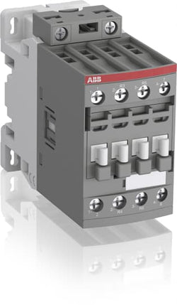
Ordering
1 piece
85364900
Popular Downloads
Dimensions
45 mm
101 mm
86 mm
0.4 kg
Technical
2
2
0
0
4P
IEC/EN 60947-1, IEC/EN 60947-4-1, UL 60335-2-40 LZGH2 A2L, UL 60947-1, UL 60947-4-1, CSA C22.2 No. 60335-2-40 LZGH2 A2L, CAN/CSA C22.2 No.60947-1, CAN/CSA C22.2 No.60947-4-1
Main Circuit 690 V
Main Circuit 50 / 60 Hz
acc. to IEC 60947-4-1, Open Contactors Θ = 40 °C 55 A
(690 V) 40 °C 55 A
(690 V) 60 °C 45 A
(690 V) 70 °C 37 A
(690 V) 40 °C 55 A
(690 V) 60 °C 45 A
(690 V) 70 °C 37 A
(415 V) 60 °C 21.2 A
(440 V) 60 °C 20 A
(500 V) 60 °C 17.6 A
(690 V) 60 °C 10.5 A
(380 / 400 V) 60 °C 22 A
(220 / 230 / 240 V) 60 °C 23.2 A
(415 V) 60 °C 21.2 A
(440 V) 60 °C 20 A
(500 V) 60 °C 17.6 A
(690 V) 60 °C 10.5 A
(380 / 400 V) 60 °C 22 A
(220 / 230 / 240 V) 60 °C 23.2 A
(400 V) 11 kW
(415 V) 11 kW
(440 V) 11 kW
(500 V) 11 kW
(690 V) 9 kW
(220 / 230 / 240 V) 5.5 kW
(400 V) 11 kW
(415 V) 11 kW
(440 V) 11 kW
(500 V) 11 kW
(690 V) 9 kW
(220 / 230 / 240 V) 5.5 kW
at 40 °C Ambient Temp, in Free Air, from a Cold State 10 s 300 A
at 40 °C Ambient Temp, in Free Air, from a Cold State 15 min 55 A
at 40 °C Ambient Temp, in Free Air, from a Cold State 1 min 150 A
at 40 °C Ambient Temp, in Free Air, from a Cold State 1 s 450 A
at 40 °C Ambient Temp, in Free Air, from a Cold State 30 s 225 A
acc. to IEC 60947-4-1 690 V
acc. to UL/CSA 600 V
acc. to IEC 60947-4-1 690 V
acc. to UL/CSA 600 V
6 kV
(AC-1) 600 cycles per hour
3600 cycles per hour
DC Operation 12 ... 20 V
at Rated Operating Conditions AC-1 per Pole 2.3 W
at Rated Operating Conditions AC-3 per Pole 0.42 W
at Rated Operating Conditions AC-1 per Pole 2.3 W
at Rated Operating Conditions AC-3 per Pole 0.42 W
Between Coil De-energization and NC Contact Closing 13 ... 98 ms
Between Coil De-energization and NO Contact Opening 11 ... 95 ms
Between Coil Energization and NC Contact Opening 38 ... 90 ms
Between Coil Energization and NO Contact Closing 40 ... 95 ms
Between Coil De-energization and NC Contact Closing 13 ... 98 ms
Between Coil De-energization and NO Contact Opening 11 ... 95 ms
Between Coil Energization and NC Contact Opening 38 ... 90 ms
Between Coil Energization and NO Contact Closing 40 ... 95 ms
TH35-15 (35 x 15 mm Mounting Rail) acc. to IEC 60715
TH35-7.5 (35 x 7.5 mm Mounting Rail) acc. to IEC 60715
TH35-15 (35 x 15 mm Mounting Rail) acc. to IEC 60715
TH35-7.5 (35 x 7.5 mm Mounting Rail) acc. to IEC 60715
2 x M4 Screws Placed Diagonally
Flexible with Ferrule 1/2x 1.5 ... 16 mm²
Flexible with Insulated Ferrule 1/2x 1.5 ... 16 mm²
Rigid Solid 1/2x 1.5 ... 4 mm²
Rigid Stranded 1/2x 1.5 ... 16 mm²
Flexible with Ferrule 1/2x 1.5 ... 16 mm²
Flexible with Insulated Ferrule 1/2x 1.5 ... 16 mm²
Rigid Solid 1/2x 1.5 ... 4 mm²
Rigid Stranded 1/2x 1.5 ... 16 mm²
Flexible with Ferrule 1/2x 0.75 ... 2.5 mm²
Flexible with Insulated Ferrule 1x 0.75 ... 2.5 mm²
Flexible with Insulated Ferrule 2x 0.75 ... 1.5 mm²
Rigid Solid 1/2x 1 ... 2.5 mm²
Rigid Stranded 1/2x 1 ... 2.5 mm²
Flexible with Ferrule 1/2x 0.75 ... 2.5 mm²
Flexible with Insulated Ferrule 1x 0.75 ... 2.5 mm²
Flexible with Insulated Ferrule 2x 0.75 ... 1.5 mm²
Rigid Solid 1/2x 1 ... 2.5 mm²
Rigid Stranded 1/2x 1 ... 2.5 mm²
Control Circuit 10 mm
Main Circuit 12 mm
Control Circuit 10 mm
Main Circuit 12 mm
acc. to IEC 60529, IEC 60947-1, EN 60529 Coil Terminals IP20
acc. to IEC 60529, IEC 60947-1, EN 60529 Main Terminals IP20
acc. to IEC 60529, IEC 60947-1, EN 60529 Coil Terminals IP20
acc. to IEC 60529, IEC 60947-1, EN 60529 Main Terminals IP20
Control Circuit 1.2 N·m
Main Circuit 2.5 N·m
Control Circuit 1.2 N·m
Main Circuit 2.5 N·m
Screw Terminals
Block Contactor
Technical UL/CSA
Main Circuit 600 V
(600 V AC) 55 A
Rigid Solid 1/2x 16-10 AWG
Rigid Stranded 1/2x 16-6 AWG
Rigid Solid 1/2x 16-10 AWG
Rigid Stranded 1/2x 16-6 AWG
Rigid Solid 1/2x 18-14 AWG
Rigid Stranded 1/2x 18-14 AWG
Rigid Solid 1/2x 18-14 AWG
Rigid Stranded 1/2x 18-14 AWG
Control Circuit 11 in·lb
Main Circuit 22 in·lb
Control Circuit 11 in·lb
Main Circuit 22 in·lb
Environmental
Close to Contactor for Storage -60 ... +80 °C
Near Contactor for Operation in Free Air -40 ... 70 °C
Close to Contactor for Storage -60 ... +80 °C
Near Contactor for Operation in Free Air -40 ... 70 °C
Category B according to IEC 60947-1 Annex Q
Without Derating 3000 m
Closed, Shock Direction: A 30 g
Closed, Shock Direction: B1 25 g
Closed, Shock Direction: B2 15 g
Closed, Shock Direction: C1 25 g
Closed, Shock Direction: C2 25 g
Open, Shock Direction: A 25 g
Open, Shock Direction: B1 5 g
Open, Shock Direction: B2 10 g
Open, Shock Direction: C1 20 g
Open, Shock Direction: C2 20 g
4g Closed Position & 2g Open position 5 ... 300 Hz
3
Material Compliance
Following EU Directive 2011/65/EU and Amendment 2015/863 July 22, 2019
Business To Business
5. Small Equipment (No External Dimension More Than 50 cm)
ABB EcoSolutions
Recycled Cardboard - 86 %
Recycled Metal - 28 %
Certificates and Declarations
Container Information
box 1 piece
87 mm
103 mm
47 mm
0.4 kg
3471523116900
box 18 piece
250 mm
300 mm
315 mm
14.4 kg
External Classifications and Standards
Q
EC000066 - Power contactor, AC switching
EC000066 - Power contactor, AC switching
EC000066 - Power contactor, AC switching
V11.0 : 27371003
39121529
4758 >> Iec Contactors
3705856

A40-30-10 24V 50Hz / 24V 60Hz Contactor
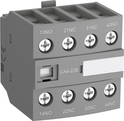
Ordering
1 piece
85389099
Popular Downloads
Dimensions
43 mm
39.5 mm
43 mm
0.055 kg
Technical
2
2
4P
IEC/EN 60947-5-1, UL 60335-2-40 LZGH2 A2L, UL 60947-5-1, CSA C22.2 No. 60335-2-40 LZGH2 A2L, CSA C22.2 No. 60947-5-1-14
Auxiliary Circuit 690 V
Auxiliary Circuit 50 / 60 Hz
acc. to IEC 60947-5-1, Θ = 40 °C 16 A
(500 V) 2 A
(690 V) 2 A
(24 / 127 V) 6 A
(220 / 240 V) 4 A
(400 / 440 V) 3 A
(500 V) 2 A
(690 V) 2 A
(24 / 127 V) 6 A
(220 / 240 V) 4 A
(400 / 440 V) 3 A
(24 V) 6 A / 144 W
(48 V) 2.8 A / 134 W
(72 V) 1 A / 72 W
(110 V) 0.55 A / 60 W
(125 V) 0.55 A / 69 W
(220 V) 0.27 A / 60 W
(250 V) 0.27 A / 68 W
(400 V) 0.15 A / 60 W
(500 V) 0.13 A / 65 W
(600 V) 0.1 A / 60 W
(24 V) 6 A / 144 W
(48 V) 2.8 A / 134 W
(72 V) 1 A / 72 W
(110 V) 0.55 A / 60 W
(125 V) 0.55 A / 69 W
(220 V) 0.27 A / 60 W
(250 V) 0.27 A / 68 W
(400 V) 0.15 A / 60 W
(500 V) 0.13 A / 65 W
(600 V) 0.1 A / 60 W
for 0.1 s 140 A
for 1 s 100 A
for 0.1 s 140 A
for 1 s 100 A
acc. to IEC 60947-5-1 690 V
acc. to UL/CSA 600 V
acc. to IEC 60947-5-1 690 V
acc. to UL/CSA 600 V
6 kV
(AC-15) 1200 cycles per hour
(DC-13) 900 cycles per hour
(AC-15) 1200 cycles per hour
(DC-13) 900 cycles per hour
3600 cycles per hour
Flexible with Ferrule 1/2x 0.75 ... 2.5 mm²
Flexible with Insulated Ferrule 2x 0.75 ... 1.5 mm²
Flexible with Insulated Ferrule 1x 0.75 ... 2.5 mm²
Rigid Solid 1/2x 1 ... 2.5 mm²
Rigid Stranded 1/2x 1 ... 2.5 mm²
Flexible with Ferrule 1/2x 0.75 ... 2.5 mm²
Flexible with Insulated Ferrule 2x 0.75 ... 1.5 mm²
Flexible with Insulated Ferrule 1x 0.75 ... 2.5 mm²
Rigid Solid 1/2x 1 ... 2.5 mm²
Rigid Stranded 1/2x 1 ... 2.5 mm²
Auxiliary Circuit 10 mm
acc. to IEC 60529, IEC 60947-1, EN 60529 Auxiliary Terminals IP20
Auxiliary Circuit 1.2 N·m
Screw Terminals
AF09
AF09Z
AF12
AF12Z
AF16
AF16Z
AFC09
AFC12
AFC16
AF09B
AF09ZB
AF12B
AF12ZB
AF16B
AF16ZB
Auxiliary Contact Block
Technical UL/CSA
Rigid Solid 1/2x 18-14 AWG
Rigid Stranded 1/2x 18-14 AWG
Rigid Solid 1/2x 18-14 AWG
Rigid Stranded 1/2x 18-14 AWG
Auxiliary Circuit 11 in·lb
Material Compliance
Following EU Directive 2011/65/EU and Amendment 2015/863 July 22, 2019
Business To Business
5. Small Equipment (No External Dimension More Than 50 cm)
Certificates and Declarations
Container Information
box 1 piece
46 mm
46 mm
46 mm
0.055 kg
3471523130203
box 192 piece
10.56 kg
External Classifications and Standards
K
EC000041 - Auxiliary contact block
EC000041 - Auxiliary contact block
EC000041 - Auxiliary contact block
V11.0 : 27371302
39121522
4743 >> Auxiliary contact block
3706519
3211422

Ordering
1 piece
85364900
Popular Downloads
Dimensions
45 mm
77 mm
92.3 mm
0.285 kg
Technical
3
0
0
1
3P
IEC/EN 60947-1, IEC/EN 60947-4-1, UL 60947-4-1, CSA C22.2 No. 60947-4-1
Auxiliary Circuit 690 V
Main Circuit 690 V
Auxiliary Circuit 690 V
Main Circuit 690 V
Auxiliary Circuit 50 / 60 Hz
Control Circuit 50 / 60 Hz
Main Circuit 50 / 60 Hz
Auxiliary Circuit 50 / 60 Hz
Control Circuit 50 / 60 Hz
Main Circuit 50 / 60 Hz
acc. to IEC 60947-4-1, Open Contactors Θ = 40 °C 35 A
acc. to IEC 60947-5-1, Θ = 40 °C 16 A
acc. to IEC 60947-4-1, Open Contactors Θ = 40 °C 35 A
acc. to IEC 60947-5-1, Θ = 40 °C 16 A
(690 V) 40 °C 25 A
(690 V) 60 °C 25 A
(690 V) 70 °C 22 A
(690 V) 40 °C 25 A
(690 V) 60 °C 25 A
(690 V) 70 °C 22 A
(415 V) 60 °C 9 A
(440 V) 60 °C 9 A
(500 V) 60 °C 9.5 A
(690 V) 60 °C 7 A
(380 / 400 V) 60 °C 9 A
(220 / 230 / 240 V) 60 °C 9 A
(415 V) 60 °C 9 A
(440 V) 60 °C 9 A
(500 V) 60 °C 9.5 A
(690 V) 60 °C 7 A
(380 / 400 V) 60 °C 9 A
(220 / 230 / 240 V) 60 °C 9 A
(415 V) 60 °C 9 A
(440 V) 60 °C 9 A
(500 V) 60 °C 9.5 A
(690 V) 60 °C 7 A
(380 / 400 V) 60 °C 9 A
(220 / 230 / 240 V) 60 °C 9 A
(415 V) 60 °C 9 A
(440 V) 60 °C 9 A
(500 V) 60 °C 9.5 A
(690 V) 60 °C 7 A
(380 / 400 V) 60 °C 9 A
(220 / 230 / 240 V) 60 °C 9 A
(500 V) 2 A
(690 V) 2 A
(24 / 127 V) 6 A
(220 / 240 V) 4 A
(400 / 440 V) 3 A
(500 V) 2 A
(690 V) 2 A
(24 / 127 V) 6 A
(220 / 240 V) 4 A
(400 / 440 V) 3 A
(110 V) 1-Pole, 40 °C 10 A
(110 V) 1-Pole, 60 °C 10 A
(110 V) 1-Pole, 70 °C 10 A
(110 V) 2 Poles in Series, 40 °C 25 A
(110 V) 2 Poles in Series, 60 °C 25 A
(110 V) 2 Poles in Series, 70 °C 22 A
(110 V) 3 Poles in Series, 40 °C 25 A
(110 V) 3 Poles in Series, 60 °C 25 A
(110 V) 3 Poles in Series, 70 °C 22 A
(220 V) 2 Poles in Series, 40 °C 10 A
(220 V) 2 Poles in Series, 60 °C 10 A
(220 V) 2 Poles in Series, 70 °C 10 A
(220 V) 3 Poles in Series, 40 °C 25 A
(220 V) 3 Poles in Series, 60 °C 25 A
(220 V) 3 Poles in Series, 70 °C 22 A
(72 V) 1-Pole, 40 °C 25 A
(72 V) 1-Pole, 60 °C 25 A
(72 V) 1-Pole, 70 °C 22 A
(72 V) 2 Poles in Series, 40 °C 25 A
(72 V) 2 Poles in Series, 60 °C 25 A
(72 V) 2 Poles in Series, 70 °C 22 A
(72 V) 3 Poles in Series, 40 °C 25 A
(72 V) 3 Poles in Series, 60 °C 25 A
(72 V) 3 Poles in Series, 70 °C 22 A
(110 V) 1-Pole, 40 °C 10 A
(110 V) 1-Pole, 60 °C 10 A
(110 V) 1-Pole, 70 °C 10 A
(110 V) 2 Poles in Series, 40 °C 25 A
(110 V) 2 Poles in Series, 60 °C 25 A
(110 V) 2 Poles in Series, 70 °C 22 A
(110 V) 3 Poles in Series, 40 °C 25 A
(110 V) 3 Poles in Series, 60 °C 25 A
(110 V) 3 Poles in Series, 70 °C 22 A
(220 V) 2 Poles in Series, 40 °C 10 A
(110 V) 1-Pole, 40 °C 6 A
(110 V) 1-Pole, 60 °C 6 A
(110 V) 1-Pole, 70 °C 6 A
(110 V) 2 Poles in Series, 40 °C 25 A
(110 V) 2 Poles in Series, 60 °C 25 A
(110 V) 2 Poles in Series, 70 °C 22 A
(110 V) 3 Poles in Series, 40 °C 25 A
(110 V) 3 Poles in Series, 60 °C 25 A
(110 V) 3 Poles in Series, 70 °C 22 A
(220 V) 2 Poles in Series, 40 °C 6 A
(220 V) 2 Poles in Series, 60 °C 6 A
(220 V) 2 Poles in Series, 70 °C 6 A
(220 V) 3 Poles in Series, 40 °C 25 A
(220 V) 3 Poles in Series, 60 °C 25 A
(220 V) 3 Poles in Series, 70 °C 22 A
(72 V) 1-Pole, 40 °C 25 A
(72 V) 1-Pole, 60 °C 25 A
(72 V) 1-Pole, 70 °C 22 A
(72 V) 2 Poles in Series, 40 °C 25 A
(72 V) 2 Poles in Series, 60 °C 25 A
(72 V) 2 Poles in Series, 70 °C 22 A
(72 V) 3 Poles in Series, 40 °C 25 A
(72 V) 3 Poles in Series, 60 °C 25 A
(72 V) 3 Poles in Series, 70 °C 22 A
(110 V) 1-Pole, 40 °C 6 A
(110 V) 1-Pole, 60 °C 6 A
(110 V) 1-Pole, 70 °C 6 A
(110 V) 2 Poles in Series, 40 °C 25 A
(110 V) 2 Poles in Series, 60 °C 25 A
(110 V) 2 Poles in Series, 70 °C 22 A
(110 V) 3 Poles in Series, 40 °C 25 A
(110 V) 3 Poles in Series, 60 °C 25 A
(110 V) 3 Poles in Series, 70 °C 22 A
(220 V) 2 Poles in Series, 40 °C 6 A
(110 V) 1-Pole, 40 °C 4 A
(110 V) 1-Pole, 60 °C 4 A
(110 V) 1-Pole, 70 °C 4 A
(110 V) 2 Poles in Series, 40 °C 10 A
(110 V) 2 Poles in Series, 60 °C 10 A
(110 V) 2 Poles in Series, 70 °C 10 A
(110 V) 3 Poles in Series, 40 °C 25 A
(110 V) 3 Poles in Series, 60 °C 25 A
(110 V) 3 Poles in Series, 70 °C 22 A
(220 V) 2 Poles in Series, 40 °C 4 A
(220 V) 2 Poles in Series, 60 °C 4 A
(220 V) 2 Poles in Series, 70 °C 4 A
(220 V) 3 Poles in Series, 40 °C 9 A
(220 V) 3 Poles in Series, 60 °C 9 A
(220 V) 3 Poles in Series, 70 °C 9 A
(72 V) 1-Pole, 40 °C 9 A
(72 V) 1-Pole, 60 °C 9 A
(72 V) 1-Pole, 70 °C 9 A
(72 V) 2 Poles in Series, 40 °C 25 A
(72 V) 2 Poles in Series, 60 °C 25 A
(72 V) 2 Poles in Series, 70 °C 22 A
(72 V) 3 Poles in Series, 40 °C 25 A
(72 V) 3 Poles in Series, 60 °C 25 A
(72 V) 3 Poles in Series, 70 °C 22 A
(110 V) 1-Pole, 40 °C 4 A
(110 V) 1-Pole, 60 °C 4 A
(110 V) 1-Pole, 70 °C 4 A
(110 V) 2 Poles in Series, 40 °C 10 A
(110 V) 2 Poles in Series, 60 °C 10 A
(110 V) 2 Poles in Series, 70 °C 10 A
(110 V) 3 Poles in Series, 40 °C 25 A
(110 V) 3 Poles in Series, 60 °C 25 A
(110 V) 3 Poles in Series, 70 °C 22 A
(220 V) 2 Poles in Series, 40 °C 4 A
(24 V) 6 A / 144 W
(48 V) 2.8 A / 134 W
(72 V) 1 A / 72 W
(110 V) 0.55 A / 60 W
(125 V) 0.55 A / 69 W
(220 V) 0.27 A / 60 W
(250 V) 0.27 A / 68 W
(400 V) 0.15 A / 60 W
(500 V) 0.13 A / 65 W
(600 V) 0.1 A / 60 W
(24 V) 6 A / 144 W
(48 V) 2.8 A / 134 W
(72 V) 1 A / 72 W
(110 V) 0.55 A / 60 W
(125 V) 0.55 A / 69 W
(220 V) 0.27 A / 60 W
(250 V) 0.27 A / 68 W
(400 V) 0.15 A / 60 W
(500 V) 0.13 A / 65 W
(600 V) 0.1 A / 60 W
(415 V) 4 kW
(440 V) 4 kW
(500 V) 5.5 kW
(690 V) 5.5 kW
(380 / 400 V) 4 kW
(220 / 230 / 240 V) 2.2 kW
(415 V) 4 kW
(440 V) 4 kW
(500 V) 5.5 kW
(690 V) 5.5 kW
(380 / 400 V) 4 kW
(220 / 230 / 240 V) 2.2 kW
(415 V) 4 kW
(440 V) 4 kW
(500 V) 5.5 kW
(690 V) 5.5 kW
(380 / 400 V) 4 kW
(220 / 230 / 240 V) 2.2 kW
(415 V) 4 kW
(440 V) 4 kW
(500 V) 5.5 kW
(690 V) 5.5 kW
(380 / 400 V) 4 kW
(220 / 230 / 240 V) 2.2 kW
at 40 °C Ambient Temp, in Free Air, from a Cold State 10 s 150 A
at 40 °C Ambient Temp, in Free Air, from a Cold State 15 min 35 A
at 40 °C Ambient Temp, in Free Air, from a Cold State 1 min 60 A
at 40 °C Ambient Temp, in Free Air, from a Cold State 1 s 300 A
at 40 °C Ambient Temp, in Free Air, from a Cold State 30 s 80 A
for 0.1 s 140 A
for 1 s 100 A
cos phi=0.45 (cos phi=0.35 for Ie > 100 A) at 440 V 250 A
cos phi=0.45 (cos phi=0.35 for Ie > 100 A) at 690 V 106 A
cos phi=0.45 (cos phi=0.35 for Ie > 100 A) at 440 V 250 A
cos phi=0.45 (cos phi=0.35 for Ie > 100 A) at 690 V 106 A
acc. to IEC 60947-4-1 690 V
acc. to IEC 60947-5-1 690 V
acc. to UL/CSA 600 V
acc. to IEC 60947-4-1 690 V
acc. to IEC 60947-5-1 690 V
acc. to UL/CSA 600 V
6 kV
(AC-1) 600 cycles per hour
(AC-15) 1200 cycles per hour
(AC-2 / AC-4) 300 cycles per hour
(AC-3) 1200 cycles per hour
(DC-13) 900 cycles per hour
(AC-1) 600 cycles per hour
(AC-15) 1200 cycles per hour
(AC-2 / AC-4) 300 cycles per hour
(AC-3) 1200 cycles per hour
(DC-13) 900 cycles per hour
3600 cycles per hour
50 Hz 100 ... 250 V
60 Hz 100 ... 250 V
DC Operation 100 ... 250 V
50 Hz 100 ... 250 V
60 Hz 100 ... 250 V
DC Operation 100 ... 250 V
at 6 A per Pole 0.1 W
at Rated Operating Conditions AC-1 per Pole 1.14 W
at Rated Operating Conditions AC-3 per Pole 0.15 W
at 6 A per Pole 0.1 W
at Rated Operating Conditions AC-1 per Pole 1.14 W
at Rated Operating Conditions AC-3 per Pole 0.15 W
Between Coil De-energization and NC Contact Closing 13 ... 98 ms
Between Coil De-energization and NO Contact Opening 11 ... 95 ms
Between Coil Energization and NC Contact Opening 38 ... 90 ms
Between Coil Energization and NO Contact Closing 40 ... 95 ms
Between Coil De-energization and NC Contact Closing 13 ... 98 ms
Between Coil De-energization and NO Contact Opening 11 ... 95 ms
Between Coil Energization and NC Contact Opening 38 ... 90 ms
Between Coil Energization and NO Contact Closing 40 ... 95 ms
TH35-15 (35 x 15 mm Mounting Rail) acc. to IEC 60715
TH35-7.5 (35 x 7.5 mm Mounting Rail) acc. to IEC 60715
TH35-15 (35 x 15 mm Mounting Rail) acc. to IEC 60715
TH35-7.5 (35 x 7.5 mm Mounting Rail) acc. to IEC 60715
2 x M4 Screws Placed Diagonally
Flexible with Ferrule 1/2x 0.5 ... 4 mm²
Flexible with Insulated Ferrule 1x 0.5 ... 4 mm²
Flexible with Insulated Ferrule 2x 0.5 ... 2.5 mm²
Flexible 1/2x 0.5 ... 4 mm²
Rigid Solid 1/2x 1 ... 2.5 mm²
Rigid Stranded 1/2x 4 ... 6 mm²
Flexible with Ferrule 1/2x 0.5 ... 4 mm²
Flexible with Insulated Ferrule 1x 0.5 ... 4 mm²
Flexible with Insulated Ferrule 2x 0.5 ... 2.5 mm²
Flexible 1/2x 0.5 ... 4 mm²
Rigid Solid 1/2x 1 ... 2.5 mm²
Rigid Stranded 1/2x 4 ... 6 mm²
Flexible with Ferrule 1/2x 0.5 ... 2.5 mm²
Flexible with Insulated Ferrule 1/2x 0.5 ... 1.5 mm²
Flexible 1/2x 0.5 ... 2.5 mm²
Rigid Solid 1/2x 1 ... 2.5 mm²
Flexible with Ferrule 1/2x 0.5 ... 2.5 mm²
Flexible with Insulated Ferrule 1/2x 0.5 ... 1.5 mm²
Flexible 1/2x 0.5 ... 2.5 mm²
Rigid Solid 1/2x 1 ... 2.5 mm²
Flexible with Ferrule 1/2x 0.5 ... 2.5 mm²
Flexible with Insulated Ferrule 1/2x 0.5 ... 1.5 mm²
Flexible 1/2x 0.5 ... 2.5 mm²
Rigid Solid 1/2x 1 ... 2.5 mm²
Flexible with Ferrule 1/2x 0.5 ... 2.5 mm²
Flexible with Insulated Ferrule 1/2x 0.5 ... 1.5 mm²
Flexible 1/2x 0.5 ... 2.5 mm²
Rigid Solid 1/2x 1 ... 2.5 mm²
Auxiliary Circuit 10 mm
Control Circuit 10 mm
Main Circuit 10 mm
Auxiliary Circuit 10 mm
Control Circuit 10 mm
Main Circuit 10 mm
acc. to IEC 60529, IEC 60947-1, EN 60529 Auxiliary Terminals IP20
acc. to IEC 60529, IEC 60947-1, EN 60529 Coil Terminals IP20
acc. to IEC 60529, IEC 60947-1, EN 60529 Main Terminals IP20
acc. to IEC 60529, IEC 60947-1, EN 60529 Auxiliary Terminals IP20
acc. to IEC 60529, IEC 60947-1, EN 60529 Coil Terminals IP20
acc. to IEC 60529, IEC 60947-1, EN 60529 Main Terminals IP20
Push-in Spring Terminals
Block Contactor
Technical UL/CSA
00
9 A
(115 V AC) Single Phase 1/3 Hp
(200 V AC) Three Phase 1-1/2 Hp
(230 V AC) Single Phase 1 Hp
(230 V AC) Three Phase 1-1/2 Hp
(460 V AC) Three Phase 2 Hp
(575 V AC) Three Phase 2 Hp
(115 V AC) Single Phase 1/3 Hp
(200 V AC) Three Phase 1-1/2 Hp
(230 V AC) Single Phase 1 Hp
(230 V AC) Three Phase 1-1/2 Hp
(460 V AC) Three Phase 2 Hp
(575 V AC) Three Phase 2 Hp
Main Circuit 600 V
(600 V AC) 25 A
(120 V AC) Single Phase 3/4 hp
(200 ... 208 V AC) Three Phase 2 hp
(220 ... 240 V AC) Three Phase 2 hp
(240 V AC) Single Phase 1-1/2 hp
(440 ... 480 V AC) Three Phase 5 hp
(550 ... 600 V AC) Three Phase 7-1/2 hp
(120 V AC) Single Phase 3/4 hp
(200 ... 208 V AC) Three Phase 2 hp
(220 ... 240 V AC) Three Phase 2 hp
(240 V AC) Single Phase 1-1/2 hp
(440 ... 480 V AC) Three Phase 5 hp
(550 ... 600 V AC) Three Phase 7-1/2 hp
Rigid Solid 1/2x 18-14 AWG
Rigid Stranded 1/2x 18-10 AWG
Rigid Solid 1/2x 18-14 AWG
Rigid Stranded 1/2x 18-10 AWG
Rigid Solid 1/2x 18-14 AWG
Rigid Solid 1/2x 18-14 AWG
(120 V AC) Single Phase 13.8 A
(200 ... 208 V AC) Three Phase 7.8 A
(220 ... 240 V AC) Three Phase 6.8 A
(240 V AC) Single Phase 10 A
(440 ... 480 V AC) Three Phase 7.6 A
(550 ... 600 V AC) Three Phase 9 A
(120 V AC) Single Phase 13.8 A
(200 ... 208 V AC) Three Phase 7.8 A
(220 ... 240 V AC) Three Phase 6.8 A
(240 V AC) Single Phase 10 A
(440 ... 480 V AC) Three Phase 7.6 A
(550 ... 600 V AC) Three Phase 9 A
Environmental
Close to Contactor without Thermal O/L Relay -40 ... 70 °C
Close to Contactor for Storage -60 ... +80 °C
Close to Contactor without Thermal O/L Relay -40 ... 70 °C
Close to Contactor for Storage -60 ... +80 °C
Category B according to IEC 60947-1 Annex Q
Without Derating 3000 m
4g Closed Position & 2g Open position 5 ... 300 Hz
3
Material Compliance
Following EU Directive 2011/65/EU and Amendment 2015/863 July 22, 2019
Business To Business
5. Small Equipment (No External Dimension More Than 50 cm)
ABB EcoSolutions
Recycled Cardboard - 86 %
Recycled Metal - 28 %
Certificates and Declarations
Container Information
box 1 piece
93 mm
86 mm
45 mm
0.3 kg
3471523154131
box 21 piece
250 mm
300 mm
315 mm
13.5 kg
External Classifications and Standards
Q
EC000066 - Power contactor, AC switching
EC000066 - Power contactor, AC switching
EC000066 - Power contactor, AC switching
V11.0 : 27371003
39121529
4758 >> Iec Contactors
3707847
3210582

Ordering
1 piece
85364900
Popular Downloads
Dimensions
45 mm
77 mm
86 mm
0.27 kg
Technical
2
2
0
0
4P
IEC/EN 60947-1, IEC/EN 60947-4-1, UL 60335-2-40 LZGH2 A2L, UL 60947-1, UL 60947-4-1, CSA C22.2 No. 60335-2-40 LZGH2 A2L, CAN/CSA C22.2 No.60947-1, CAN/CSA C22.2 No.60947-4-1
Main Circuit 690 V
Control Circuit 50 / 60 Hz
Main Circuit 50 / 60 Hz
Control Circuit 50 / 60 Hz
Main Circuit 50 / 60 Hz
acc. to IEC 60947-4-1, Open Contactors Θ = 40 °C 35 A
(690 V) 40 °C 25 A
(690 V) 60 °C 25 A
(690 V) 70 °C 22 A
(690 V) 40 °C 25 A
(690 V) 60 °C 25 A
(690 V) 70 °C 22 A
(415 V) 60 °C 9 A
(440 V) 60 °C 9 A
(500 V) 60 °C 9.5 A
(690 V) 60 °C 7 A
(380 / 400 V) 60 °C 9 A
(220 / 230 / 240 V) 60 °C 9 A
(415 V) 60 °C 9 A
(440 V) 60 °C 9 A
(500 V) 60 °C 9.5 A
(690 V) 60 °C 7 A
(380 / 400 V) 60 °C 9 A
(220 / 230 / 240 V) 60 °C 9 A
(400 V) 4 kW
(415 V) 4 kW
(440 V) 4 kW
(500 V) 5.5 kW
(690 V) 5.5 kW
(380 / 400 V) 4 kW
(220 / 230 / 240 V) 2.2 kW
(400 V) 4 kW
(415 V) 4 kW
(440 V) 4 kW
(500 V) 5.5 kW
(690 V) 5.5 kW
(380 / 400 V) 4 kW
(220 / 230 / 240 V) 2.2 kW
at 40 °C Ambient Temp, in Free Air, from a Cold State 10 s 150 A
at 40 °C Ambient Temp, in Free Air, from a Cold State 15 min 35 A
at 40 °C Ambient Temp, in Free Air, from a Cold State 1 min 60 A
at 40 °C Ambient Temp, in Free Air, from a Cold State 1 s 300 A
at 40 °C Ambient Temp, in Free Air, from a Cold State 30 s 80 A
cos phi=0.45 (cos phi=0.35 for Ie > 100 A) at 440 V 250 A
cos phi=0.45 (cos phi=0.35 for Ie > 100 A) at 690 V 106 A
cos phi=0.45 (cos phi=0.35 for Ie > 100 A) at 440 V 250 A
cos phi=0.45 (cos phi=0.35 for Ie > 100 A) at 690 V 106 A
acc. to IEC 60947-4-1 690 V
acc. to UL/CSA 600 V
acc. to IEC 60947-4-1 690 V
acc. to UL/CSA 600 V
6 kV
(AC-1) 600 cycles per hour
3600 cycles per hour
50 Hz 24 ... 60 V
60 Hz 24 ... 60 V
DC Operation 20 ... 60 V
50 Hz 24 ... 60 V
60 Hz 24 ... 60 V
DC Operation 20 ... 60 V
at Rated Operating Conditions AC-1 per Pole 0.8 W
at Rated Operating Conditions AC-3 per Pole 0.1 W
at Rated Operating Conditions AC-1 per Pole 0.8 W
at Rated Operating Conditions AC-3 per Pole 0.1 W
Between Coil De-energization and NC Contact Closing 13 ... 98 ms
Between Coil De-energization and NO Contact Opening 11 ... 95 ms
Between Coil Energization and NC Contact Opening 38 ... 90 ms
Between Coil Energization and NO Contact Closing 40 ... 95 ms
Between Coil De-energization and NC Contact Closing 13 ... 98 ms
Between Coil De-energization and NO Contact Opening 11 ... 95 ms
Between Coil Energization and NC Contact Opening 38 ... 90 ms
Between Coil Energization and NO Contact Closing 40 ... 95 ms
TH35-15 (35 x 15 mm Mounting Rail) acc. to IEC 60715
TH35-7.5 (35 x 7.5 mm Mounting Rail) acc. to IEC 60715
TH35-15 (35 x 15 mm Mounting Rail) acc. to IEC 60715
TH35-7.5 (35 x 7.5 mm Mounting Rail) acc. to IEC 60715
2 x M4 Screws Placed Diagonally
Flexible with Ferrule 1/2x 0.75 ... 6 mm²
Flexible with Insulated Ferrule 1x 0.75 ... 4 mm²
Flexible with Insulated Ferrule 2x 0.75 ... 2.5 mm²
Rigid Solid 1/2x 1 ... 4 mm²
Rigid Stranded 1/2x 1 ... 6 mm²
Flexible with Ferrule 1/2x 0.75 ... 6 mm²
Flexible with Insulated Ferrule 1x 0.75 ... 4 mm²
Flexible with Insulated Ferrule 2x 0.75 ... 2.5 mm²
Rigid Solid 1/2x 1 ... 4 mm²
Rigid Stranded 1/2x 1 ... 6 mm²
Rigid Solid 1/2x 1 ... 2.5 mm²
Rigid Stranded 1/2x 1 ... 2.5 mm²
Rigid Solid 1/2x 1 ... 2.5 mm²
Rigid Stranded 1/2x 1 ... 2.5 mm²
Flexible with Ferrule 1/2x 0.75 ... 2.5 mm²
Flexible with Insulated Ferrule 1x 0.75 ... 2.5 mm²
Flexible with Insulated Ferrule 2x 0.75 ... 1.5 mm²
Rigid Solid 1/2x 1 ... 2.5 mm²
Rigid Stranded 1/2x 1 ... 2.5 mm²
Flexible with Ferrule 1/2x 0.75 ... 2.5 mm²
Flexible with Insulated Ferrule 1x 0.75 ... 2.5 mm²
Flexible with Insulated Ferrule 2x 0.75 ... 1.5 mm²
Rigid Solid 1/2x 1 ... 2.5 mm²
Rigid Stranded 1/2x 1 ... 2.5 mm²
Control Circuit 10 mm
Main Circuit 10 mm
Control Circuit 10 mm
Main Circuit 10 mm
acc. to IEC 60529, IEC 60947-1, EN 60529 Coil Terminals IP20
acc. to IEC 60529, IEC 60947-1, EN 60529 Main Terminals IP20
acc. to IEC 60529, IEC 60947-1, EN 60529 Coil Terminals IP20
acc. to IEC 60529, IEC 60947-1, EN 60529 Main Terminals IP20
Control Circuit 1.2 N·m
Main Circuit 1.5 N·m
Control Circuit 1.2 N·m
Main Circuit 1.5 N·m
Screw Terminals
Block Contactor
Technical UL/CSA
Main Circuit 600 V
(600 V AC) 25 A
Rigid Solid 1/2x 16-10 AWG
Rigid Stranded 1/2x 16-10 AWG
Rigid Solid 1/2x 16-10 AWG
Rigid Stranded 1/2x 16-10 AWG
Rigid Solid 1/2x 18-14 AWG
Rigid Stranded 1/2x 18-14 AWG
Rigid Solid 1/2x 18-14 AWG
Rigid Stranded 1/2x 18-14 AWG
Rigid Solid 1/2x 18-14 AWG
Rigid Stranded 1/2x 18-14 AWG
Rigid Solid 1/2x 18-14 AWG
Rigid Stranded 1/2x 18-14 AWG
Control Circuit 11 in·lb
Main Circuit 13 in·lb
Control Circuit 11 in·lb
Main Circuit 13 in·lb
Environmental
Close to Contactor for Storage -60 ... +80 °C
Near Contactor for Operation in Free Air -40 ... 70 °C
Close to Contactor for Storage -60 ... +80 °C
Near Contactor for Operation in Free Air -40 ... 70 °C
Category B according to IEC 60947-1 Annex Q
Without Derating 3000 m
Closed, Shock Direction: B1 25 g
Open, Shock Direction: B1 5 g
Shock Direction: A 30 g
Shock Direction: B2 15 g
Shock Direction: C1 25 g
Shock Direction: C2 25 g
Closed, Shock Direction: B1 25 g
Open, Shock Direction: B1 5 g
Shock Direction: A 30 g
Shock Direction: B2 15 g
Shock Direction: C1 25 g
Shock Direction: C2 25 g
4g Closed Position & 2g Open position 5 ... 300 Hz
3
Material Compliance
Following EU Directive 2011/65/EU and Amendment 2015/863 July 22, 2019
dfe04cfe-21a2-43c5-b543-6c5355a10fc6 China
0bbefb09-f1ca-4341-9c11-d49a631b5179 Germany
9a805ffa-4538-470a-917d-5a7fc47172e8 Croatia
15574661-aef8-4ad6-bc3c-4843022b4d84 Belgium
4480c85c-aa35-4597-9e8c-de620e90354c France
860e6779-38aa-4004-9066-a3fb38872bbd Sweden
58624de8-78cb-4bc0-a0e8-51e5743d8295 Poland
1f9f0c98-5b9a-4c53-975f-bcde1e5c64b2 Germany
dab0e41d-3783-4aa3-964b-f43f616a74ba Germany
a81149d3-c906-4280-ba08-a56556e15899 Sweden
d3cf6163-288f-4653-943d-85346fe36a10 Denmark
467f565a-b5b1-471f-b38c-fa6b63d4c317 Germany
80301ffe-d51f-48cb-959b-40a6ee831957 Germany
13a37a1f-cd33-4e41-81dc-b0b56dbb1665 Norway
2d65a655-4431-429f-9117-6f10d525f2df Netherlands
77e6f57e-565d-4e84-a59c-3d7d8f4adc14 Poland
1c5cc9d1-cf11-4189-b248-289788a2d60c Poland
994d3602-d0c7-493e-ba70-589795ac925a Hungary
af7e4ba8-3315-4393-9ec9-af997b19f3e5 Hungary
82103918-dc38-43b7-b7d1-4a575f4df25d Estonia
726c6487-468d-48fa-990d-ef7bccc73a64 Finland
08bca821-db92-437e-a9cc-83e6b67d669b Bulgaria
059136ae-debb-46c4-ab69-c09831d97f05 Portugal
0c57ffe9-5f54-4f30-be5d-ff9d1dae807d Belgium
0ba9f390-ed7f-42b8-a0a2-e4dff20269de Greece
a0f6ba9c-8814-4247-bdc1-ff0aa41ca327 France
e6bb34d3-01e5-4568-bad3-ff247fec28d8 Spain
2494bd0d-d124-4198-9fd4-b189e657f7b0 Czech Republic
0bbefb09-f1ca-4341-9c11-d49a631b5179 Germany
9a805ffa-4538-470a-917d-5a7fc47172e8 Croatia
15574661-aef8-4ad6-bc3c-4843022b4d84 Belgium
4480c85c-aa35-4597-9e8c-de620e90354c France
860e6779-38aa-4004-9066-a3fb38872bbd Sweden
58624de8-78cb-4bc0-a0e8-51e5743d8295 Poland
1f9f0c98-5b9a-4c53-975f-bcde1e5c64b2 Germany
dab0e41d-3783-4aa3-964b-f43f616a74ba Germany
a81149d3-c906-4280-ba08-a56556e15899 Sweden
d3cf6163-288f-4653-943d-85346fe36a10 Denmark
Business To Business
5. Small Equipment (No External Dimension More Than 50 cm)
ABB EcoSolutions
Recycled Cardboard - 86 %
Recycled Metal - 28 %
Certificates and Declarations
Container Information
box 1 piece
87 mm
79 mm
47 mm
0.27 kg
3471523116214
box 27 piece
250 mm
300 mm
315 mm
14.58 kg
External Classifications and Standards
Q
EC000066 - Power contactor, AC switching
EC000066 - Power contactor, AC switching
EC000066 - Power contactor, AC switching
V11.0 : 27371003
39121529
4758 >> Iec Contactors
3705811
3211407

Ordering
1 piece
85364900
Popular Downloads
Dimensions
55 mm
119.5 mm
111 mm
0.98 kg
Technical
3
0
0
0
3P
IEC/EN 60947-1, IEC/EN 60947-4-1, UL 60947-4-1, CSA C22.2 No. 60947-4-1, UL 60335-2-40 LZGH2 A2L
Main Circuit 690 V
acc. to IEC 60947-4-1, Open Contactors Θ = 40 °C 105 A
(690 V) 40 °C 100 A
(690 V) 60 °C 80 A
(690 V) 70 °C 70 A
(690 V) 40 °C 100 A
(690 V) 60 °C 80 A
(690 V) 70 °C 70 A
(415 V) 60 °C 53 A
(440 V) 60 °C 53 A
(500 V) 60 °C 45 A
(690 V) 60 °C 35 A
(380 / 400 V) 60 °C 53 A
(220 / 230 / 240 V) 60 °C 53 A
(415 V) 60 °C 53 A
(440 V) 60 °C 53 A
(500 V) 60 °C 45 A
(690 V) 60 °C 35 A
(380 / 400 V) 60 °C 53 A
(220 / 230 / 240 V) 60 °C 53 A
(415 V) 60 °C 53 A
(440 V) 60 °C 53 A
(500 V) 60 °C 45 A
(690 V) 60 °C 35 A
(380 / 400 V) 60 °C 53 A
(220 / 230 / 240 V) 60 °C 53 A
(415 V) 60 °C 53 A
(440 V) 60 °C 53 A
(500 V) 60 °C 45 A
(690 V) 60 °C 35 A
(380 / 400 V) 60 °C 53 A
(220 / 230 / 240 V) 60 °C 53 A
(415 V) 30 kW
(440 V) 30 kW
(500 V) 30 kW
(690 V) 30 kW
(380 / 400 V) 22 kW
(220 / 230 / 240 V) 15 kW
(415 V) 30 kW
(440 V) 30 kW
(500 V) 30 kW
(690 V) 30 kW
(380 / 400 V) 22 kW
(220 / 230 / 240 V) 15 kW
(415 V) 30 kW
(440 V) 30 kW
(500 V) 30 kW
(690 V) 30 kW
(380 / 400 V) 22 kW
(220 / 230 / 240 V) 15 kW
(415 V) 30 kW
(440 V) 30 kW
(500 V) 30 kW
(690 V) 30 kW
(380 / 400 V) 22 kW
(220 / 230 / 240 V) 15 kW
(400 / 415 V) 40 °C, 50 / 60 Hz 43 kvar
(400 / 415 V) 70 °C, 50 / 60 Hz 39 kvar
(400 / 415 V) 55 °C, 50 / 60 Hz 43 kvar
(440 V) 40 °C, 50 / 60 Hz 15.5 kvar
(500 / 550 V), 40 °C, 50 / 60 Hz 54 kvar
(500 / 550 V) 55 °C, 50 / 60 Hz 54 kvar
(500 / 550 V) 70 °C, 50 / 60 Hz 48.5 kvar
(690 V) 40 °C, 50 / 60 Hz 74 kvar
(690 V) 55 °C, 50 / 60 Hz 74 kvar
(690 V) 70 °C, 50 / 60 Hz 67 kvar
at 40 °C Ambient Temp, in Free Air, from a Cold State 15 min 110 A
at 40 °C Ambient Temp, in Free Air, from a Cold State 1 min 250 A
at 40 °C Ambient Temp, in Free Air, from a Cold State 1 s 1000 A
at 40 °C Ambient Temp, in Free Air, from a Cold State 30 s 350 A
at 40 °C Ambient Temp, in Free Air, from a Cold State 15 min 110 A
at 40 °C Ambient Temp, in Free Air, from a Cold State 1 min 250 A
at 40 °C Ambient Temp, in Free Air, from a Cold State 1 s 1000 A
at 40 °C Ambient Temp, in Free Air, from a Cold State 30 s 350 A
cos phi=0.45 (cos phi=0.35 for Ie > 100 A) at 440 V 950 A
cos phi=0.45 (cos phi=0.35 for Ie > 100 A) at 690 V 600 A
cos phi=0.45 (cos phi=0.35 for Ie > 100 A) at 440 V 950 A
cos phi=0.45 (cos phi=0.35 for Ie > 100 A) at 690 V 600 A
acc. to IEC 60947-4-1 and VDE 0110 (Gr. C) 690 V
acc. to UL/CSA 600 V
acc. to IEC 60947-4-1 and VDE 0110 (Gr. C) 690 V
acc. to UL/CSA 600 V
Auxiliary Circuit 6 kV
(AC-1) 600 cycles per hour
(AC-2 / AC-4) 150 cycles per hour
(AC-3) 1200 cycles per hour
(AC-1) 600 cycles per hour
(AC-2 / AC-4) 150 cycles per hour
(AC-3) 1200 cycles per hour
3600 cycles per hour
50 Hz 220 ... 230 V
60 Hz 230 ... 240 V
50 Hz 220 ... 230 V
60 Hz 230 ... 240 V
Average Holding Value 50 / 60 Hz 20 V·A
Average Pull-in Value 50 Hz 150 V·A
Average Pull-in Value 60 Hz 151 V·A
Average Holding Value 50 / 60 Hz 20 V·A
Average Pull-in Value 50 Hz 150 V·A
Average Pull-in Value 60 Hz 151 V·A
at Rated Operating Conditions AC-1 per Pole 6.3 W
at Rated Operating Conditions AC-3 per Pole 1.7 W
at Rated Operating Conditions AC-1 per Pole 6.3 W
at Rated Operating Conditions AC-3 per Pole 1.7 W
Between Coil De-energization and NC Contact Closing 6 ... 19 ms
Between Coil De-energization and NO Contact Opening 4 ... 14 ms
Between Coil Energization and NC Contact Opening 3 ... 16 ms
Between Coil Energization and NO Contact Closing 7 ... 21 ms
Between Coil De-energization and NC Contact Closing 6 ... 19 ms
Between Coil De-energization and NO Contact Opening 4 ... 14 ms
Between Coil Energization and NC Contact Opening 3 ... 16 ms
Between Coil Energization and NO Contact Closing 7 ... 21 ms
TH35-15 (35 x 15 mm Mounting Rail) acc. to IEC 60715
TH35-7.5 (35 x 7.5 mm Mounting Rail) acc. to IEC 60715
TH35-15 (35 x 15 mm Mounting Rail) acc. to IEC 60715
TH35-7.5 (35 x 7.5 mm Mounting Rail) acc. to IEC 60715
2 x M4 or 2 x M6 Screws Placed Diagonally
Flexible with Ferrule 1/2x 4 ... 35 mm²
Flexible with Insulated Ferrule 1/2x 4 ... 35 mm²
Rigid 1/2x 6 ... 3 5 mm²
Flexible with Ferrule 1/2x 4 ... 35 mm²
Flexible with Insulated Ferrule 1/2x 4 ... 35 mm²
Rigid 1/2x 6 ... 3 5 mm²
Flexible with Ferrule 1/2x 0.75 ... 2.5 mm²
Flexible with Insulated Ferrule 1x 0.75 ... 2.5 mm²
Flexible with Insulated Ferrule 2x 0.75 ... 1.5 mm²
Flexible with Insulated Ferrule 1x 0.75 ... 2.5 mm²
Flexible with Insulated Ferrule 2x 0.75 ... 1.5 mm²
Rigid 1/2x 1 ... 2.5 mm²
Flexible with Ferrule 1/2x 0.75 ... 2.5 mm²
Flexible with Insulated Ferrule 1x 0.75 ... 2.5 mm²
Flexible with Insulated Ferrule 2x 0.75 ... 1.5 mm²
Flexible with Insulated Ferrule 1x 0.75 ... 2.5 mm²
Flexible with Insulated Ferrule 2x 0.75 ... 1.5 mm²
Rigid 1/2x 1 ... 2.5 mm²
Control Circuit 10 mm
Main Circuit 16 mm
Control Circuit 10 mm
Main Circuit 16 mm
acc. to IEC 60529, IEC 60947-1, EN 60529 Auxiliary Terminals IP20
acc. to IEC 60529, IEC 60947-1, EN 60529 Coil Terminals IP20
acc. to IEC 60529, IEC 60947-1, EN 60529 Main Terminals IP10
acc. to IEC 60529, IEC 60947-1, EN 60529 Auxiliary Terminals IP20
acc. to IEC 60529, IEC 60947-1, EN 60529 Coil Terminals IP20
acc. to IEC 60529, IEC 60947-1, EN 60529 Main Terminals IP10
Main Circuit 6.5
Main Circuit Slot
Control Circuit 5.5
Control Circuit Slot
Main Circuit 6.5
Main Circuit Slot
Control Circuit 5.5
Control Circuit Slot
Control Circuit 1.2 N·m
Main Circuit 4 N·m
Control Circuit 1.2 N·m
Main Circuit 4 N·m
Screw Terminals
Block Contactor
Technical UL/CSA
Main Circuit 600 V
(600 V AC) 80 A
(120 V AC) Single Phase 3 hp
(200 ... 208 V AC) Three Phase 15 hp
(220 ... 240 V AC) Three Phase 20 hp
(240 V AC) Single Phase 10 hp
(440 ... 480 V AC) Three Phase 40 hp
(550 ... 600 V AC) Three Phase 50 hp
(120 V AC) Single Phase 3 hp
(200 ... 208 V AC) Three Phase 15 hp
(220 ... 240 V AC) Three Phase 20 hp
(240 V AC) Single Phase 10 hp
(440 ... 480 V AC) Three Phase 40 hp
(550 ... 600 V AC) Three Phase 50 hp
Control Circuit 11 in·lb
Main Circuit 35 in·lb
Control Circuit 11 in·lb
Main Circuit 35 in·lb
(120 V AC) Single Phase 34 A
(200 ... 208 V AC) Three Phase 48.3 A
(220 ... 240 V AC) Three Phase 54 A
(240 V AC) Single Phase 50 A
(440 ... 480 V AC) Three Phase 52 A
(550 ... 600 V AC) Three Phase 52 A
(120 V AC) Single Phase 34 A
(200 ... 208 V AC) Three Phase 48.3 A
(220 ... 240 V AC) Three Phase 54 A
(240 V AC) Single Phase 50 A
(440 ... 480 V AC) Three Phase 52 A
(550 ... 600 V AC) Three Phase 52 A
Environmental
Close to Contactor without Thermal O/L Relay -40 ... 70 °C
Close to Contactor for Storage -60 ... +80 °C
Close to Contactor without Thermal O/L Relay -40 ... 70 °C
Close to Contactor for Storage -60 ... +80 °C
Category B according to IEC 60947-1 Annex Q
Without Derating 3000 m
Closed, Shock Direction: A 25 g
Closed, Shock Direction: B1 25 g
Closed, Shock Direction: B2 15 g
Closed, Shock Direction: C1 25 g
Closed, Shock Direction: C2 25 g
Open, Shock Direction: B1 5 g
Closed, Shock Direction: A 25 g
Closed, Shock Direction: B1 25 g
Closed, Shock Direction: B2 15 g
Closed, Shock Direction: C1 25 g
Closed, Shock Direction: C2 25 g
Open, Shock Direction: B1 5 g
3
Material Compliance
Following EU Directive 2011/65/EU and Amendment 2015/863 July 22, 2019
Business To Business
5. Small Equipment (No External Dimension More Than 50 cm)
Certificates and Declarations
Container Information
box 1 piece
146.5 mm
96.5 mm
146.5 mm
1.1 kg
3471523018839
External Classifications and Standards
Q
EC000066 - Power contactor, AC switching
EC000066 - Power contactor, AC switching
EC000066 - Power contactor, AC switching
V11.0 : 27371003
39121529
4758 >> Iec Contactors
Ordering
1 piece
85364900
Popular Downloads
Dimensions
70 mm
113.5 mm
125.5 mm
1.21 kg
Technical
4
0
0
0
4P
IEC/EN 60947-1, IEC/EN 60947-4-1, UL 60335-2-40 LZGH2 A2L, UL 60947-1, UL 60947-4-1, CSA C22.2 No. 60335-2-40 LZGH2 A2L, CSA C22.2 No. 60947-1:22, CSA C22.2 No. 60947-4-1:22
Main Circuit 690 V
Control Circuit 50 / 60 Hz
Main Circuit 50 / 60 Hz
Control Circuit 50 / 60 Hz
Main Circuit 50 / 60 Hz
acc. to IEC 60947-4-1, Open Contactors Θ = 40 °C 105 A
(690 V) 40 °C 70 A
(690 V) 60 °C 60 A
(690 V) 70 °C 50 A
(690 V) 40 °C 70 A
(690 V) 60 °C 60 A
(690 V) 70 °C 50 A
(415 V) 60 °C 40 A
(440 V) 60 °C 40 A
(500 V) 60 °C 35 A
(690 V) 60 °C 25 A
(380 / 400 V) 60 °C 40 A
(220 / 230 / 240 V) 60 °C 40 A
(415 V) 60 °C 40 A
(440 V) 60 °C 40 A
(500 V) 60 °C 35 A
(690 V) 60 °C 25 A
(380 / 400 V) 60 °C 40 A
(220 / 230 / 240 V) 60 °C 40 A
(415 V) 22 kW
(440 V) 22 kW
(500 V) 22 kW
(690 V) 22 kW
(380 / 400 V) 18.5 kW
(220 / 230 / 240 V) 11 kW
(415 V) 22 kW
(440 V) 22 kW
(500 V) 22 kW
(690 V) 22 kW
(380 / 400 V) 18.5 kW
(220 / 230 / 240 V) 11 kW
at 40 °C Ambient Temp, in Free Air, from a Cold State 10 s 600 A
at 40 °C Ambient Temp, in Free Air, from a Cold State 15 min 110 A
at 40 °C Ambient Temp, in Free Air, from a Cold State 1 min 250 A
at 40 °C Ambient Temp, in Free Air, from a Cold State 1 s 1000 A
at 40 °C Ambient Temp, in Free Air, from a Cold State 30 s 350 A
cos phi=0.45 (cos phi=0.35 for Ie > 100 A) at 440 V 950 A
cos phi=0.45 (cos phi=0.35 for Ie > 100 A) at 690 V 600 A
cos phi=0.45 (cos phi=0.35 for Ie > 100 A) at 440 V 950 A
cos phi=0.45 (cos phi=0.35 for Ie > 100 A) at 690 V 600 A
acc. to IEC 60947-4-1 690 V
acc. to UL/CSA 600 V
acc. to IEC 60947-4-1 690 V
acc. to UL/CSA 600 V
6 kV
(AC-1) 600 cycles per hour
3600 cycles per hour
50 Hz 48 ... 130 V
60 Hz 48 ... 130 V
DC Operation 48 ... 130 V
50 Hz 48 ... 130 V
60 Hz 48 ... 130 V
DC Operation 48 ... 130 V
Average Holding Value 50 / 60 Hz 4 V·A
Average Holding Value 50 Hz 4 V·A
Average Holding Value 60 Hz 4 V·A
Average Holding Value DC 2 W
Average Holding Value, from Warm State 2 W
Average Holding Value 50 / 60 Hz 4 V·A
Average Holding Value 50 Hz 4 V·A
Average Holding Value 60 Hz 4 V·A
Average Holding Value DC 2 W
Average Holding Value, from Warm State 2 W
at Rated Operating Conditions AC-1 per Pole 3 W
at Rated Operating Conditions AC-3 per Pole 1 W
at Rated Operating Conditions AC-1 per Pole 3 W
at Rated Operating Conditions AC-3 per Pole 1 W
TH35-15 (35 x 15 mm Mounting Rail) acc. to IEC 60715
2 x M4 or 2 x M6 Screws Placed Diagonally
Flexible with Ferrule 1/2x 4 ... 35 mm²
Flexible with Insulated Ferrule 1/2x 4 ... 35 mm²
Rigid Stranded 1/2x 6 ... 35 mm²
Flexible with Ferrule 1/2x 4 ... 35 mm²
Flexible with Insulated Ferrule 1/2x 4 ... 35 mm²
Rigid Stranded 1/2x 6 ... 35 mm²
Flexible with Ferrule 1/2x 0.75 ... 2.5 mm²
Flexible with Insulated Ferrule 1x 0.75 ... 2.5 mm²
Flexible with Insulated Ferrule 2x 0.75 ... 1.5 mm²
Rigid Solid 1/2x 1 ... 2.5 mm²
Rigid Stranded 1/2x 1 ... 2.5 mm²
Flexible with Ferrule 1/2x 0.75 ... 2.5 mm²
Flexible with Insulated Ferrule 1x 0.75 ... 2.5 mm²
Flexible with Insulated Ferrule 2x 0.75 ... 1.5 mm²
Rigid Solid 1/2x 1 ... 2.5 mm²
Rigid Stranded 1/2x 1 ... 2.5 mm²
Control Circuit 10 mm
Main Circuit 16 mm
Control Circuit 10 mm
Main Circuit 16 mm
acc. to IEC 60529, IEC 60947-1, EN 60529 Coil Terminals IP20
acc. to IEC 60529, IEC 60947-1, EN 60529 Main Terminals IP10
acc. to IEC 60529, IEC 60947-1, EN 60529 Coil Terminals IP20
acc. to IEC 60529, IEC 60947-1, EN 60529 Main Terminals IP10
Pozidriv PZ
Control Circuit 1.2 N·m
Main Circuit 4 N·m
Control Circuit 1.2 N·m
Main Circuit 4 N·m
Screw Terminals
Block Contactor
Technical UL/CSA
Main Circuit 600 V
(600 V AC) 60 A
Rigid Stranded 1/2x 10-2 AWG
Rigid Solid 1/2x 18-14 AWG
Rigid Stranded 1/2x 18-14 AWG
Rigid Solid 1/2x 18-14 AWG
Rigid Stranded 1/2x 18-14 AWG
Control Circuit 11 in·lb
Main Circuit 35 in·lb
Control Circuit 11 in·lb
Main Circuit 35 in·lb
(120 V AC) Single Phase 3 A
(200 ... 208 V AC) Three Phase 10 A
(220 ... 240 V AC) Three Phase 15 A
(240 V AC) Single Phase 7-1/2 A
(440 ... 480 V AC) Three Phase 30 A
(550 ... 600 V AC) Three Phase 40 A
(120 V AC) Single Phase 3 A
(200 ... 208 V AC) Three Phase 10 A
(220 ... 240 V AC) Three Phase 15 A
(240 V AC) Single Phase 7-1/2 A
(440 ... 480 V AC) Three Phase 30 A
(550 ... 600 V AC) Three Phase 40 A
Environmental
Close to Contactor for Storage -60 ... +80 °C
Near Contactor for Operation in Free Air -40 ... 70 °C
Close to Contactor for Storage -60 ... +80 °C
Near Contactor for Operation in Free Air -40 ... 70 °C
Category B according to IEC 60947-1 Annex Q
Without Derating 3000 m
3g Closed Position & 2g Open Position 5 ... 300 Hz
3
Material Compliance
Following EU Directive 2011/65/EU and Amendment 2015/863 July 22, 2019
1f3c3920-80ae-47fc-8aab-9e9b06ef32ef China
cc165340-5aa6-4207-be7a-fc7d5d2e4187 Spain
579027e4-1532-4afe-bf6a-1f4c7b254b8f Czech Republic
71eaaa00-025d-4bac-bea7-1d1d99629dbd Denmark
ede2dc64-35fa-4cbc-9888-9d5e60cfd6ce Poland
a1186246-9702-4c70-b25d-de41c1265608 Germany
e2281066-473c-4010-9098-41a17d841147 Belgium
7a8228be-a725-4d97-897f-4f6bef2ca097 Sweden
48226d14-4654-46f1-afdf-b6ed11b20f49 Germany
6539ed2b-5f28-4809-9de7-52a94fc491d5 Germany
1f151365-4cd0-46c2-adc6-997fcd005034 Croatia
a2729a8b-8e1c-4741-ad02-5992655763d3 Poland
490282ea-11aa-4e76-bb3f-f683a44ff93f Germany
cec92b17-0c34-46dc-a51d-64fccc0e8521 France
35f9f1bf-f324-4ea9-8562-321e8d0e277d Sweden
da3fce96-1feb-40ff-a08f-593360955e4c Germany
93aff7d9-3244-4c7a-948b-c9e9aebe8a49 Finland
fa18672e-2ce5-49f3-9320-aa6724b2590e Bulgaria
babd48c8-c66c-483f-bc05-bf0a3b8258bc Estonia
2ec7a8c5-9eba-4e23-888e-04a7b9e8ed81 Hungary
10fc7e11-f1da-45eb-926c-092e4fe3767a Norway
a15eb6f5-b4f7-410f-8070-5442baa8fd50 Hungary
f866a0d3-4099-4a29-922b-0ccd66e0ab01 Poland
50c89aa5-0222-4a42-a955-16bbcc1e87fd Netherlands
f673bb20-283e-46ca-a79d-ae5b2c135f9c Belgium
e727b2b1-fbb3-488b-90a3-e0cd8aab00df Greece
9956541a-cc0e-4167-8fc1-40848218480a Portugal
554a72c2-bb41-4f10-b387-8c4cbe911f8d France
cc165340-5aa6-4207-be7a-fc7d5d2e4187 Spain
579027e4-1532-4afe-bf6a-1f4c7b254b8f Czech Republic
71eaaa00-025d-4bac-bea7-1d1d99629dbd Denmark
ede2dc64-35fa-4cbc-9888-9d5e60cfd6ce Poland
a1186246-9702-4c70-b25d-de41c1265608 Germany
e2281066-473c-4010-9098-41a17d841147 Belgium
7a8228be-a725-4d97-897f-4f6bef2ca097 Sweden
48226d14-4654-46f1-afdf-b6ed11b20f49 Germany
6539ed2b-5f28-4809-9de7-52a94fc491d5 Germany
1f151365-4cd0-46c2-adc6-997fcd005034 Croatia
Business To Business
5. Small Equipment (No External Dimension More Than 50 cm)
ABB EcoSolutions
Yes
FSC Recycled Paper - 94.6 %
Recycled Metal - 28.2 %
Certificates and Declarations
Container Information
box 1 piece
150 mm
150 mm
103 mm
1.32 kg
3471523133525
box 8 piece
250 mm
300 mm
300 mm
10.56 kg
External Classifications and Standards
Q
EC000066 - Power contactor, AC switching
EC000066 - Power contactor, AC switching
EC000066 - Power contactor, AC switching
V11.0 : 27371003
39121529
4758 >> Iec Contactors
3707256
3210297
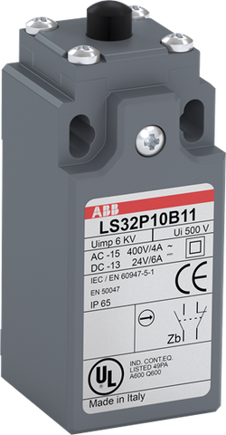
Ordering
1 piece
85364900
Popular Downloads
Dimensions
30 mm
73 mm
30 mm
0.058 kg
Technical
Snap Action Simultaneous
plain plastic plunger
Operations 30 Millions
acc. to IEC 60947-5-1, Θ = 40 °C 10 A
acc. to IEC 60529 IP65
Plastic
(AC-15) 3600 cycles per hour
(DC-13) 3600 cycles per hour
(AC-15) 3600 cycles per hour
(DC-13) 3600 cycles per hour
1 NO, 1 NC
15 million
30 mm (EN 50047)
1 x M16x1.5 - Bottom
A600
Q600
A600
Q600
6 kV
(230 V AC) 3.1 A
(400 V) NC 4
(24 V) 10 A
(130 V) 5.5 A
(240 V) 3 A
(230 V AC) 3.1 A
(400 V) NC 4
(24 V) 10 A
(130 V) 5.5 A
(240 V) 3 A
acc. to IEC 60947-5-1 and VDE 0110 (Gr. C) 500 V
acc. to UL/CSA 600 V
acc. to IEC 60947-5-1 and VDE 0110 (Gr. C) 500 V
acc. to UL/CSA 600 V
(24 V) 6 A
(110 V) 0.6 A
(125 V) 0.55 A
(250 V) 0.4 A
(24 V) 6 A
(110 V) 0.6 A
(125 V) 0.55 A
(250 V) 0.4 A
gG Type Fuses 10 A
Environmental
Operation -25 ... +70 °C
Storage -30 ... +80 °C
Operation -25 ... +70 °C
Storage -30 ... +80 °C
Material Compliance
Following EU Directive 2011/65/EU and Amendment 2015/863 July 22, 2019
Business To Business
5. Small Equipment (No External Dimension More Than 50 cm)
Certificates and Declarations
Container Information
box 1 piece
35 mm
32 mm
95 mm
0.068 kg
3471522613660
External Classifications and Standards
B
EC000030 - End switch
EC000030 - End switch
V11.0 : 27272601
39121500
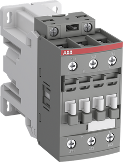
Ordering
1 piece
85364900
Popular Downloads
Dimensions
45 mm
106 mm
86 mm
0.48 kg
Technical
3
0
0
0
3P
IEC/EN 60947-1, IEC/EN 60947-4-1, UL 60335-2-40 LZGH2 A2L, UL 60947-4-1, CSA C22.2 No. 60335-2-40 LZGH2 A2L, CSA C22.2 No. 60947-4-1
Main Circuit 690 V
Main Circuit 50 / 60 Hz
acc. to IEC 60947-4-1, Open Contactors Θ = 40 °C 50 A
acc. to IEC 60947-5-1, Θ = 40 °C 16 A
acc. to IEC 60947-4-1, Open Contactors Θ = 40 °C 50 A
acc. to IEC 60947-5-1, Θ = 40 °C 16 A
(690 V) 40 °C 45 A
(690 V) 60 °C 40 A
(690 V) 70 °C 32 A
(690 V) 40 °C 45 A
(690 V) 60 °C 40 A
(690 V) 70 °C 32 A
(415 V) 60 °C 26 A
(440 V) 60 °C 26 A
(500 V) 60 °C 23 A
(690 V) 60 °C 17 A
(380 / 400 V) 60 °C 26 A
(220 / 230 / 240 V) 60 °C 26 A
(415 V) 60 °C 26 A
(440 V) 60 °C 26 A
(500 V) 60 °C 23 A
(690 V) 60 °C 17 A
(380 / 400 V) 60 °C 26 A
(220 / 230 / 240 V) 60 °C 26 A
(415 V) 60 °C 26 A
(440 V) 60 °C 26 A
(500 V) 60 °C 23 A
(690 V) 60 °C 17 A
(380 / 400 V) 60 °C 26 A
(220 / 230 / 240 V) 60 °C 26 A
(415 V) 60 °C 26 A
(440 V) 60 °C 26 A
(500 V) 60 °C 23 A
(690 V) 60 °C 17 A
(380 / 400 V) 60 °C 26 A
(220 / 230 / 240 V) 60 °C 26 A
(110 V) 2 Poles in Series, 40 °C 45 A
(110 V) 2 Poles in Series, 60 °C 40 A
(110 V) 2 Poles in Series, 70 °C 32 A
(110 V) 3 Poles in Series, 40 °C 45 A
(110 V) 3 Poles in Series, 60 °C 40 A
(110 V) 3 Poles in Series, 70 °C 32 A
(220 V) 3 Poles in Series, 40 °C 45 A
(220 V) 3 Poles in Series, 60 °C 40 A
(220 V) 3 Poles in Series, 70 °C 32 A
(72 V) 1-Pole, 40 °C 45 A
(72 V) 1-Pole, 60 °C 40 A
(72 V) 1-Pole, 70 °C 32 A
(72 V) 2 Poles in Series, 40 °C 45 A
(72 V) 2 Poles in Series, 60 °C 40 A
(72 V) 2 Poles in Series, 70 °C 32 A
(72 V) 3 Poles in Series, 40 °C 45 A
(72 V) 3 Poles in Series, 60 °C 40 A
(72 V) 3 Poles in Series, 70 °C 32 A
(110 V) 2 Poles in Series, 40 °C 45 A
(110 V) 2 Poles in Series, 60 °C 40 A
(110 V) 2 Poles in Series, 70 °C 32 A
(110 V) 3 Poles in Series, 40 °C 45 A
(110 V) 3 Poles in Series, 60 °C 40 A
(110 V) 3 Poles in Series, 70 °C 32 A
(220 V) 3 Poles in Series, 40 °C 45 A
(220 V) 3 Poles in Series, 60 °C 40 A
(220 V) 3 Poles in Series, 70 °C 32 A
(72 V) 1-Pole, 40 °C 45 A
(72 V) 1-Pole, 60 °C 40 A
(72 V) 1-Pole, 70 °C 32 A
(72 V) 2 Poles in Series, 40 °C 45 A
(72 V) 2 Poles in Series, 60 °C 40 A
(72 V) 2 Poles in Series, 70 °C 32 A
(72 V) 3 Poles in Series, 40 °C 45 A
(72 V) 3 Poles in Series, 60 °C 40 A
(72 V) 3 Poles in Series, 70 °C 32 A
(110 V) 2 Poles in Series, 40 °C 45 A
(110 V) 2 Poles in Series, 60 °C 40 A
(110 V) 2 Poles in Series, 70 °C 32 A
(110 V) 3 Poles in Series, 40 °C 45 A
(110 V) 3 Poles in Series, 60 °C 40 A
(110 V) 3 Poles in Series, 70 °C 32 A
(220 V) 3 Poles in Series, 40 °C 45 A
(220 V) 3 Poles in Series, 60 °C 40 A
(220 V) 3 Poles in Series, 70 °C 32 A
(72 V) 1-Pole, 40 °C 45 A
(110 V) 2 Poles in Series, 40 °C 45 A
(110 V) 2 Poles in Series, 60 °C 40 A
(110 V) 2 Poles in Series, 70 °C 32 A
(110 V) 3 Poles in Series, 40 °C 45 A
(110 V) 3 Poles in Series, 60 °C 40 A
(110 V) 3 Poles in Series, 70 °C 32 A
(220 V) 3 Poles in Series, 40 °C 20 A
(220 V) 3 Poles in Series, 60 °C 20 A
(220 V) 3 Poles in Series, 70 °C 20 A
(72 V) 1-Pole, 40 °C 20 A
(72 V) 1-Pole, 60 °C 20 A
(72 V) 1-Pole, 70 °C 20 A
(72 V) 2 Poles in Series, 40 °C 45 A
(72 V) 2 Poles in Series, 60 °C 40 A
(72 V) 2 Poles in Series, 70 °C 32 A
(72 V) 3 Poles in Series, 40 °C 45 A
(72 V) 3 Poles in Series, 60 °C 40 A
(72 V) 3 Poles in Series, 70 °C 32 A
(110 V) 2 Poles in Series, 40 °C 45 A
(110 V) 2 Poles in Series, 60 °C 40 A
(110 V) 2 Poles in Series, 70 °C 32 A
(110 V) 3 Poles in Series, 40 °C 45 A
(110 V) 3 Poles in Series, 60 °C 40 A
(110 V) 3 Poles in Series, 70 °C 32 A
(220 V) 3 Poles in Series, 40 °C 20 A
(220 V) 3 Poles in Series, 60 °C 20 A
(220 V) 3 Poles in Series, 70 °C 20 A
(72 V) 1-Pole, 40 °C 20 A
(415 V) 11 kW
(440 V) 15 kW
(500 V) 15 kW
(690 V) 15 kW
(380 / 400 V) 11 kW
(220 / 230 / 240 V) 6.5 kW
(415 V) 11 kW
(440 V) 15 kW
(500 V) 15 kW
(690 V) 15 kW
(380 / 400 V) 11 kW
(220 / 230 / 240 V) 6.5 kW
(415 V) 11 kW
(440 V) 15 kW
(500 V) 15 kW
(690 V) 15 kW
(380 / 400 V) 11 kW
(220 / 230 / 240 V) 6.5 kW
(415 V) 11 kW
(440 V) 15 kW
(500 V) 15 kW
(690 V) 15 kW
(380 / 400 V) 11 kW
(220 / 230 / 240 V) 6.5 kW
at 40 °C Ambient Temp, in Free Air, from a Cold State 10 s 350 A
at 40 °C Ambient Temp, in Free Air, from a Cold State 15 min 50 A
at 40 °C Ambient Temp, in Free Air, from a Cold State 1 min 150 A
at 40 °C Ambient Temp, in Free Air, from a Cold State 1 s 700 A
at 40 °C Ambient Temp, in Free Air, from a Cold State 30 s 225 A
cos phi=0.45 (cos phi=0.35 for Ie > 100 A) at 440 V 500 A
cos phi=0.45 (cos phi=0.35 for Ie > 100 A) at 690 V 200 A
cos phi=0.45 (cos phi=0.35 for Ie > 100 A) at 440 V 500 A
cos phi=0.45 (cos phi=0.35 for Ie > 100 A) at 690 V 200 A
acc. to IEC 60947-4-1 690 V
acc. to UL/CSA 600 V
acc. to IEC 60947-4-1 690 V
acc. to UL/CSA 600 V
6 kV
(AC-1) 600 cycles per hour
(AC-2 / AC-4) 150 cycles per hour
(AC-3) 1200 cycles per hour
(AC-1) 600 cycles per hour
(AC-2 / AC-4) 150 cycles per hour
(AC-3) 1200 cycles per hour
3600 cycles per hour
DC Operation 24 V
at Rated Operating Conditions AC-1 per Pole 1.8 W
at Rated Operating Conditions AC-3 per Pole 0.6 W
at Rated Operating Conditions AC-1 per Pole 1.8 W
at Rated Operating Conditions AC-3 per Pole 0.6 W
Between Coil De-energization and NC Contact Closing 22 ... 57 ms
Between Coil De-energization and NO Contact Opening 17 ... 29 ms
Between Coil Energization and NC Contact Opening 20 ... 35 ms
Between Coil Energization and NO Contact Closing 27 ... 53 ms
Between Coil De-energization and NC Contact Closing 22 ... 57 ms
Between Coil De-energization and NO Contact Opening 17 ... 29 ms
Between Coil Energization and NC Contact Opening 20 ... 35 ms
Between Coil Energization and NO Contact Closing 27 ... 53 ms
TH35-15 (35 x 15 mm Mounting Rail) acc. to IEC 60715
TH35-7.5 (35 x 7.5 mm Mounting Rail) acc. to IEC 60715
TH35-15 (35 x 15 mm Mounting Rail) acc. to IEC 60715
TH35-7.5 (35 x 7.5 mm Mounting Rail) acc. to IEC 60715
2 x M4 Screws Placed Diagonally
Flexible with Ferrule 1/2x 1.5 ... 10 mm²
Flexible with Insulated Ferrule 1x 1.5 ... 10 mm²
Flexible with Insulated Ferrule 2x 1.5 ... 4 mm²
Rigid Solid 1/2x 2.5 ... 4 mm²
Rigid Stranded 1/2x 2.5 ... 10 mm²
Flexible with Ferrule 1/2x 1.5 ... 10 mm²
Flexible with Insulated Ferrule 1x 1.5 ... 10 mm²
Flexible with Insulated Ferrule 2x 1.5 ... 4 mm²
Rigid Solid 1/2x 2.5 ... 4 mm²
Rigid Stranded 1/2x 2.5 ... 10 mm²
Flexible with Ferrule 1/2x 0.75 ... 2.5 mm²
Flexible with Insulated Ferrule 1x 0.75 ... 2.5 mm²
Flexible with Insulated Ferrule 2x 0.75 ... 1.5 mm²
Rigid Solid 1/2x 1 ... 2.5 mm²
Rigid Stranded 1/2x 1 ... 2.5 mm²
Flexible with Ferrule 1/2x 0.75 ... 2.5 mm²
Flexible with Insulated Ferrule 1x 0.75 ... 2.5 mm²
Flexible with Insulated Ferrule 2x 0.75 ... 1.5 mm²
Rigid Solid 1/2x 1 ... 2.5 mm²
Rigid Stranded 1/2x 1 ... 2.5 mm²
Control Circuit 10 mm
Main Circuit 14 mm
Control Circuit 10 mm
Main Circuit 14 mm
acc. to IEC 60529, IEC 60947-1, EN 60529 Coil Terminals IP20
acc. to IEC 60529, IEC 60947-1, EN 60529 Main Terminals IP20
acc. to IEC 60529, IEC 60947-1, EN 60529 Coil Terminals IP20
acc. to IEC 60529, IEC 60947-1, EN 60529 Main Terminals IP20
Control Circuit 1.2 N·m
Main Circuit 2.5 N·m
Control Circuit 1.2 N·m
Main Circuit 2.5 N·m
Screw Terminals
Block Contactor
Technical UL/CSA
1
27 A
(115 V AC) Single Phase 2 Hp
(200 V AC) Three Phase 7-1/2 Hp
(230 V AC) Single Phase 3 Hp
(230 V AC) Three Phase 7-1/2 Hp
(460 V AC) Three Phase 10 Hp
(575 V AC) Three Phase 10 Hp
(115 V AC) Single Phase 2 Hp
(200 V AC) Three Phase 7-1/2 Hp
(230 V AC) Single Phase 3 Hp
(230 V AC) Three Phase 7-1/2 Hp
(460 V AC) Three Phase 10 Hp
(575 V AC) Three Phase 10 Hp
Main Circuit 600 V
(600 V AC) 45 A
(120 V AC) Single Phase 2 hp
(200 ... 208 V AC) Three Phase 7-1/2 hp
(220 ... 240 V AC) Three Phase 7-1/2 hp
(240 V AC) Single Phase 3 hp
(440 ... 480 V AC) Three Phase 15 hp
(550 ... 600 V AC) Three Phase 20 hp
(120 V AC) Single Phase 2 hp
(200 ... 208 V AC) Three Phase 7-1/2 hp
(220 ... 240 V AC) Three Phase 7-1/2 hp
(240 V AC) Single Phase 3 hp
(440 ... 480 V AC) Three Phase 15 hp
(550 ... 600 V AC) Three Phase 20 hp
Rigid Solid 1/2x 14-10 AWG
Rigid Stranded 1/2x 14-8 AWG
Rigid Solid 1/2x 14-10 AWG
Rigid Stranded 1/2x 14-8 AWG
Rigid Solid 1/2x 18-14 AWG
Rigid Stranded 1/2x 18-14 AWG
Rigid Solid 1/2x 18-14 AWG
Rigid Stranded 1/2x 18-14 AWG
Control Circuit 11 in·lb
Main Circuit 22 in·lb
Control Circuit 11 in·lb
Main Circuit 22 in·lb
(120 V AC) Single Phase 24 A
(200 ... 208 V AC) Three Phase 25.3 A
(220 ... 240 V AC) Three Phase 22 A
(240 V AC) Single Phase 17 A
(440 ... 480 V AC) Three Phase 21 A
(550 ... 600 V AC) Three Phase 22 A
(120 V AC) Single Phase 24 A
(200 ... 208 V AC) Three Phase 25.3 A
(220 ... 240 V AC) Three Phase 22 A
(240 V AC) Single Phase 17 A
(440 ... 480 V AC) Three Phase 21 A
(550 ... 600 V AC) Three Phase 22 A
Environmental
Close to Contactor Fitted with Thermal O/L Relay -25 ... 60 °C
Close to Contactor without Thermal O/L Relay -40 ... 70 °C
Close to Contactor for Storage -60 ... +80 °C
Close to Contactor Fitted with Thermal O/L Relay -25 ... 60 °C
Close to Contactor without Thermal O/L Relay -40 ... 70 °C
Close to Contactor for Storage -60 ... +80 °C
Category B according to IEC 60947-1 Annex Q
Without Derating 3000 m
4g Closed Position & 2g Open position 5 ... 300 Hz
3
Material Compliance
Following EU Directive 2011/65/EU and Amendment 2015/863 July 22, 2019
2fbd5275-78f3-436f-bde9-7a77b01a8ecb France
d08024f1-2432-4f51-9080-c1c65b4513d8 France
9601629d-2bf9-43aa-98de-0853325777e3 Germany
c0736a89-6e5e-487f-b351-a3c31a597664 Germany
0e58a387-f7f8-40fc-bf36-6dc93bff6f96 Finland
374fc693-875d-49cb-9ab8-a352c0a26a0a Italy
20ad2a47-a3cf-42ad-8a7e-146584316b07 Norway
6dea00f9-9afc-45ef-93b6-7feae691c7a2 Croatia
24d425fc-1f08-4d9d-bdf2-a65d29c7c816 Spain
f3e47c3b-58b3-41fe-9e79-0824b63bf321 Germany
f34a7be2-9841-4254-8e95-62ee9ebbcce7 Netherlands
03b4ae88-a7de-4579-8bff-03516beb7cb1 Greece
38f706ac-8684-4340-ac50-ac4b6a6d8618 Portugal
b8803a8d-8b08-4aa3-a8aa-e13a168dc34e Hungary
d16085f2-fc18-4b0b-9908-a88d7acb5243 Belgium
36f3126f-6450-4fee-8de2-f4434ee7c80d Belgium
29df22a7-15e9-4d3f-87c4-003e264867da Hungary
25abe974-9dd6-4edb-9702-e4e10797648b Bulgaria
4108df82-e0ae-4ec9-91ad-b8e7d175cf2b Denmark
13d17387-bc1d-4592-b3ba-57040d4d282d Germany
4ab3a4e1-e0aa-4e1a-b5ad-6050f6355d7c Czech Republic
eb4f9547-dce1-439b-83a4-ee6aa78084ba Poland
6ef4d94f-3ea3-4385-8855-5f2aa50c4fec Estonia
c5c9cfa4-9053-4fe4-80d6-5e647b1ae497 Sweden
036ff80f-6f94-480b-a967-fc332bc8456f Poland
4f9c6dcb-7ac2-4f80-bef3-5d3d16e105b9 Germany
7e101ee3-bc7b-43fc-96eb-f7324d5ad773 Poland
48334337-5a8e-4787-a228-8d33a715bb21 Sweden
d08024f1-2432-4f51-9080-c1c65b4513d8 France
9601629d-2bf9-43aa-98de-0853325777e3 Germany
c0736a89-6e5e-487f-b351-a3c31a597664 Germany
0e58a387-f7f8-40fc-bf36-6dc93bff6f96 Finland
374fc693-875d-49cb-9ab8-a352c0a26a0a Italy
20ad2a47-a3cf-42ad-8a7e-146584316b07 Norway
6dea00f9-9afc-45ef-93b6-7feae691c7a2 Croatia
24d425fc-1f08-4d9d-bdf2-a65d29c7c816 Spain
f3e47c3b-58b3-41fe-9e79-0824b63bf321 Germany
f34a7be2-9841-4254-8e95-62ee9ebbcce7 Netherlands
Business To Business
5. Small Equipment (No External Dimension More Than 50 cm)
ABB EcoSolutions
Recycled Cardboard - 86 %
Recycled Metal - 28 %
Certificates and Declarations
Container Information
box 1 piece
96 mm
112 mm
50 mm
0.526 kg
3471523114197
crate 12 piece
51 mm
98 mm
114 mm
6.312 kg
External Classifications and Standards
Q
EC000066 - Power contactor, AC switching
EC000066 - Power contactor, AC switching
EC000066 - Power contactor, AC switching
V11.0 : 27371003
39121529
4758 >> Iec Contactors
3709060

PLC Direct is not an authorized distributor. We offer a broad range of in-stock products with minimal lead time.