
 1 year warranty


Specifications
Model |
SL-V104H |
|||
Detection capability |
ø0.98" ø25 mm |
|||
Beam axis spacing/Lens diameter |
20 mm/ø5 mm 0.79"/ø0.20" |
|||
Effective aperture angle |
Max. ±2.5 ° (When operating distance is 3 m 98.23' or more) |
|||
Working distance |
0.1 to 7 m |
|||
Response time (ms) |
ON→OFF |
20.2*1 |
||
OFF→ON |
60.2*1 |
|||
Light source |
Infrared LED (850 nm) |
|||
Operation mode |
Turns on when no interruptions are present in the detection zone (excluding when the muting function is used) |
|||
OSSD output |
Output |
2 outputs each for PNP and NPN. Can be changed by using the connector cable. |
||
Max. l oad current |
500 mA*2 |
|||
Residual vol tage (during ON) |
Max. 2.5 V (with a cable length of 7 m 22.97') |
|||
Leakage current |
Max. 100 µA*3 |
|||
Max. capacitive load |
2.2 µF (with a load resistance of 100 Ω) |
|||
Load wiring resistance |
Max. 2.5 Ω*4 |
|||
Non safety-rel ated output |
AUX |
Output with automatic PNP/NPN switching function, 50 mA max. |
||
Interlock-reset-ready output | ||||
Alarm output | ||||
Clear/blocked output | ||||
State information output 1, 2 | ||||
Muting lamp output |
Incandescent lamp (24 VDC, 1 to 7 W) or LED lamp (load current: 10 to 300 mA)*5 can be connected |
|||
Input |
EDM input |
Short-circuit current 10 mA |
||
Wait input |
Short-circuit current 2.5 mA |
|||
Reset input | ||||
Muting input 1, 2 | ||||
Override input | ||||
Protection circuit |
Reverse current protection, short-circuit protection for each output, surge protection for each output |
|||
Approved standards |
EMC |
EMS |
IEC61496-1, EN61496-1, UL61496-1 |
|
EMI |
EN55011 Class A, FCC Part15B Class A |
|||
Safety |
IEC61496-1, EN61496-1, UL61496-1 (Type 4 ESPE) |
|||
Rating |
Power voltage |
24 VDC +10 %, -20 %, Ripple (P-P) 10 % or less |
||
Current consumption (mA) |
When the center indicator is ON |
Transmitter |
159*6 |
|
Receiver |
107*6 |
|||
When the center indicator is OFF |
Transmitter |
143*6 |
||
Receiver |
84*6 |
|||
Environmental resistance |
Enclosure rating |
IP65 (IEC60529) |
||
Overvoltage category |
II |
|||
Ambient light |
Incandescent lamp: 5,000 lux max., Sunlight: 20,000 lux max. |
|||
Operating ambient temperature |
-10 to +55 °C 14 to 131 °F (No freezing) |
|||
Operating relative humidity |
15 to 85 % RH (No condensation) |
|||
Storage temperature |
-25 to +60 °C -13 to 140 °F (No freezing) |
|||
Storage relative humidity |
15 to 95 % RH |
|||
Vibration resistance |
10 to 55 Hz, Double amplitude 0.7 mm 0.03", 20 sweeps in each of the X, Y, and Z directions |
|||
Shock resistance |
100 m/s2 (Approx. 10 G), 16 ms pulse, 1,000 times in each of the X, Y, and Z directions |
|||
Material |
Main unit case |
Aluminum |
||
Upper case/lower case |
Zinc die-cast |
|||
Front cover |
Polycarbonate, SUS304 |
|||
Weight |
Transmitter |
1,360 g |
||
Receiver |
1,405 g |
|||
*1 When connecting the SL-V units in series, the response time (ON to OFF) is the sum of the response times of al l the individual SL-V units, but the response time (OFF to ON) is the same as that of a singl e SL-V unit. | ||||
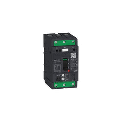
Motor circuit breaker, TeSys GV4, 3P, 3.5A, Icu 100kA, thermal magnetic, Everlink terminals


plug in base, Compact NSX 400/630, front/rear connected, 3 poles
PLC Direct is not an authorized distributor. We offer a broad range of in-stock products with minimal lead time.

PLC Direct is not an authorized distributor. We offer a broad range of in-stock products with minimal lead time.


trip unit Micrologic 6.3 E for Compact NSX 630 circuit breakers, electronic, rating 630A, 4 poles 4d


Specifications
Model |
PR-F51N1 |
|||
Type |
Thrubeam |
|||
Output |
NPN |
|||
Shape |
Flat |
|||
Cable connection |
1 m cable |
|||
Detection distance |
0.6 m |
|||
Number of control outputs |
2 outputs |
|||
Output operation |
Output 1 |
Dark-ON |
||
Output 2 |
Light-ON |
|||
Response time |
Output 1 |
0.5 ms |
||
Output 2 |
ON→OFF: 2.7 ms, OFF→ON: 0.5 ms |
|||
Sensitivity adjustment |
None |
|||
Spot diameter |
- |
|||
Light source |
4 element, point light source, red LED (650 nm) |
|||
Mutual interference prevention function |
- |
|||
Indicator lamp |
Output indicator (orange), stable operation indicator (green), thrubeam type transmitter: power supply indicator (green) |
|||
Control output |
30 VDC or lower, 50 mA or lower |
|||
Protection circuit |
Power supply reverse connection protection, output overcurrent protection, |
|||
Rating |
Power voltage |
10 to 30 VDC, including Ripple (P-P) 10 % |
||
Current consumption |
Transmitter: 11 mA, Receiver: 16 mA |
|||
Environmental resistance |
Enclosure rating |
IP67 (IEC60529), IP69K (DIN40050-9), 4X, 6P, 13 (NEMA250) |
||
Insulation resistance |
20 MΩ or higher (500 VDC) |
|||
Ambient light |
Incandescent lamp: 5,000 lux or lower, Sunlight: 20,000 lux or lower |
|||
Ambient temperature |
-25 to +55 °C -13 to 131 °F (No freezing) |
|||
Relative humidity |
35 to 85 % RH (No condensation) |
|||
Storage temperature |
-25 to +75 °C -13 to 167 °F |
|||
Withstand voltage |
1,000 VAC, 50/60 Hz, 1 min |
|||
Vibration resistance |
10 to 55 Hz, Double amplitude 1.5 mm 0.06", 2 hours in each of the X, Y, and Z directions |
|||
Shock resistance |
1,000 m/s2, 6 times in each of the X, Y, and Z directions |
|||
Material |
Case: SUS316L, indicator cover/lens cover: polysulfone, |
|||
Accessories |
Instruction manual |
|||
Weight |
Approx. 36 g |
|||

PLC Direct is not an authorized distributor. We offer a broad range of in-stock products with minimal lead time.
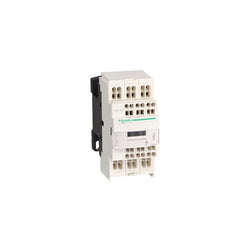
TeSys D control relay - 3 NO + 2 NC - <= 690 V - 24 V DC standard coil
ABB EcoSolutions
Technical
Electrical
Material Compliance
Environmental
Dimensions
Engineering
Ordering
Certificates and Declarations
Installation
Popular Downloads
External Classifications and Standards
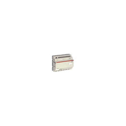
CPU logic module and inputs / outputs. CL-LER.18DC2 Mod. Of expansion 24V c.c. with 12 digital inputs and 6 relay outputs expansion outputs / outputs
Main
| Characteristic | Value(s) |
|---|---|
| Range of Product | Altivar |
| Product or Component Type | Variable speed drive |
| Product Specific Application | Simple machine |
| Component name | ATV31 |
| Assembly style | With heat sink |
| Variant | With drive order potentiometer |
| EMC filter | Integrated |
| [Us] rated supply voltage | 380...500 V - 5...5 % |
| Supply frequency | 50...60 Hz - 5...5 % |
| Phase | 3 phase |
| Motor power kW | 11 kW 4 kHz |
| Maximum Horse Power Rating | 15 hp 4 kHz |
| Line current | 28.4 A 500 V 37.2 A 380 V, Isc = 1 kA |
| Apparent power | 25 kVA |
| Prospective line Isc | 1 kA |
| Nominal output current | 27.7 A 4 kHz |
| Maximum transient current | 41.6 A 60 s |
| Power dissipation in W | 397 W at nominal load |
| Asynchronous motor control profile | Sensorless flux vector control with PWM type motor control signal Factory set : constant torque |
| Analogue input number | 4 |
Complementary
| Characteristic | Value(s) |
|---|---|
| Product destination | Asynchronous motors |
| Supply voltage limits | 323â¦550 V |
| Network Frequency | 47.5...63 Hz |
| Output frequency | 0.0005â¦0.5 kHz |
| Nominal switching frequency | 4 kHz |
| Switching frequency | 2...16 kHz adjustable |
| Speed range | 1â¦50 |
| Transient overtorque | 150â¦170 % of nominal motor torque |
| Braking torque | <= 150 % 60 s with braking resistor 100 % with braking resistor continuously 150 % without braking resistor |
| Regulation loop | Frequency PI regulator |
| Motor slip compensation | Suppressable Adjustable Automatic whatever the load |
| Output voltage | <= power supply voltage |
| Electrical connection | Al1, Al2, Al3, AOV, AOC, R1A, R1B, R1C, R2A, R2B, LI1...LI6 terminal 0.004 in² (2.5 mm²) AWG 14 L1, L2, L3, U, V, W, PA, PB, PA/+, PC/- terminal 0.004 in² (2.5 mm²) AWG 14 |
| Tightening torque | Al1, Al2, Al3, AOV, AOC, R1A, R1B, R1C, R2A, R2B, LI1...LI6 5.3 lbf.in (0.6 N.m) L1, L2, L3, U, V, W, PA, PB, PA/+, PC/- 7.08 lbf.in (0.8 N.m) |
| Insulation | Electrical between power and control |
| Supply | Internal supply for logic inputs 19...30 V 100 mA overload and short-circuit protection Internal supply for reference potentiometer (2.2 to 10 kOhm) 10...10.8 V 10 mA overload and short-circuit protection |
| Analogue input type | AI3 configurable current 0...20 mA 250 Ohm AI1 configurable voltage 0...10 V 30 V max 30000 Ohm AI2 configurable voltage +/- 10 V 30 V max 30000 Ohm AIP potentiometer reference 8 ms 10 bits +/- 4.3 % +/- 0.2 % |
| Sampling duration | LI1...LI6 4 ms discrete AI1, AI2, AI3 8 ms analog |
| Response time | AOV, AOC 8 ms analog R1A, R1B, R1C, R2A, R2B 8 ms discrete |
| Linearity error | +/- 0.2 % output |
| Analogue output number | 2 |
| Analogue output type | AOC configurable current 0...20 mA 800 Ohm 8 bits AOV configurable voltage 0...10 V 470 Ohm 8 bits |
| Discrete input logic | Positive logic (source) LI1...LI6), < 5 V, > 11 V Logic input not wired LI1...LI4), < 13 V Negative logic (source) LI1...LI6), > 19 V |
| Discrete output number | 2 |
| Discrete output type | Configurable relay logic R1A, R1B, R1C) 1 NO + 1 NC - 100000 cycles Configurable relay logic R2A, R2B) NC - 100000 cycles |
| Minimum switching current | R1-R2 10 mA 5 V DC |
| Maximum switching current | R1-R2 2 A 250 V AC inductive, cos phi = 0.4 7 ms R1-R2 2 A 30 V DC inductive, cos phi = 0.4 7 ms R1-R2 5 A 250 V AC resistive, cos phi = 1 0 ms R1-R2 5 A 30 V DC resistive, cos phi = 1 0 ms |
| Discrete input number | 6 |
| Discrete input type | LI1...LI6) programmable 24 V, 0â¦100 mA PLC 3500 Ohm |
| Acceleration and deceleration ramps | S, U or customized Linear adjustable separately from 0.1 to 999.9 s |
| Braking to standstill | By DC injection |
| Protection type | Input phase breaks drive Line supply overvoltage and undervoltage safety circuits drive Line supply phase loss safety function, for three phases supply drive Motor phase breaks drive Overcurrent between output phases and earth (on power up only) drive Overheating protection drive Short-circuit between motor phases drive Thermal protection motor |
| Insulation resistance | >= 500 mOhm 500 V DC for 1 minute |
| Display type | 1 LED Red)drive voltage Four 7-segment display unitsCANopen bus status |
| Time constant | 5 ms for reference change |
| Frequency resolution | Display unit 0.1 Hz Analog input 0.1...100 Hz |
| Connector type | 1 RJ45 CANopen via VW3 CANTAP2 adaptor 1 RJ45 Modbus |
| Physical interface | RS485 multidrop serial link CANopen via VW3 CANTAP2 adaptor RS485 multidrop serial link Modbus |
| Transmission frame | RTU CANopen via VW3 CANTAP2 adaptor RTU Modbus |
| Transmission Rate | 10, 20, 50, 125, 250, 500 kbps or 1 Mbps CANopen via VW3 CANTAP2 adaptor 4800, 9600 or 19200 bps Modbus |
| Number of addresses | 1â¦127 CANopen via VW3 CANTAP2 adaptor 1â¦247 Modbus |
| Number of drive | 127 CANopen via VW3 CANTAP2 adaptor 31 Modbus |
| Marking | CE |
| Operating position | Vertical +/- 10 degree |
| Product Weight | 24.3 lb(US) (11 kg) |

Ordering
Popular Downloads
Dimensions
Technical
Material Compliance
Certificates and Declarations
Container Information
External Classifications and Standards

