
 1 year warranty

| Product | |
| Article Number (Market Facing Number) | 6SL32101KE132AF2 | 6SL32101KE132AF2 |
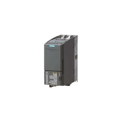
| Product Description | SINAMICS g120c rated power 1,1K 150% overload for 3 sec 3AC380- +10/-20% 47-63HZ integrated fil a i/o-interface 6di, 2do,1ai,1a torque off integrated fieldbus PROFINET-pn protection IP20/ ul type size fsaa 173x73x178(hxwxd external 24v |
| Product family | Ordering Data Overview |
| Product Lifecycle (PLM) | PM300:Active Product |
| Additional Product Information | |
| EAN | 4042948668764 |
| UPC | 804766249563 |
| Commodity Code | 85044095 |
| LKZ_FDB/ CatalogID | D11.1SD |
| Product Group | 5673 |
| Group Code | R220 |
| Country of origin | Great Britain |
| SCIP number | Not available |
| Delivery information | |
| Net Weight (lb) | 3.086 lb |
| Package size unit of measure | Inch |
| Packaging Quantity | 1 |
| Product | |
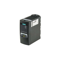
| Article Number (Market Facing Number) | 6SE64402UD155AA1 | 6SE64402UD155AA1 |
| Product Description | |
| Product family | Not available |
| Product Lifecycle (PLM) | PM410:Product cancellation |
| Additional Product Information | |
| EAN | 4019169450324 |
| UPC | 783087635678 |
| Commodity Code | 85044095 |
| LKZ_FDB/ CatalogID | DA51-E |
| Product Group | 9848 |
| Group Code | R2S3 |
| Country of origin | Great Britain |
| SCIP number | Not available |
| Delivery information | |
| Net Weight (lb) | 2.866 lb |
| Package size unit of measure | Inch |
| Packaging Quantity | 1 |

| Product | |
| Article Number (Market Facing Number) | 6ES75050RA000AB0 | 6ES75050RA000AB0 |
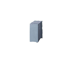
| Product Description | SIMATIC S7-1500, System power supply PS 60W 24/48/60 V DC, supplies the backplane bus of the S7-1500 with operating voltage |
| Product family | System power supplies |
| Product Lifecycle (PLM) | PM300:Active Product |
| Additional Product Information | |
| EAN | 4025515080152 |
| UPC | 887621139636 |
| Commodity Code | 85044095 |
| LKZ_FDB/ CatalogID | ST73 |
| Product Group | 4500 |
| Group Code | R132 |
| Country of origin | Germany |
| SCIP number | Not available |
| Delivery information | |
| Net Weight (lb) | 1.437 lb |
| Package size unit of measure | Inch |
| Packaging Quantity | 1 |
| Product | |
| Article Number (Market Facing Number) | 6ES75070RA000AB0 | 6ES75070RA000AB0 |
| Product Description | SIMATIC S7-1500, system power supply PS 60W 120/230V AC/DC, supplies the backplane bus of S7-1500 with operating voltage |
| Product family | System power supplies |
| Product Lifecycle (PLM) | PM300:Active Product |
| Additional Product Information | |
| EAN | 4025515080169 |
| UPC | 887621139643 |
| Commodity Code | 85044095 |
| LKZ_FDB/ CatalogID | ST73 |
| Product Group | 4500 |
| Group Code | R132 |
| Country of origin | Germany |
| SCIP number | d3b9b7e3-6dba-4eea-9aaa-b5f45a3319c9 |
| Delivery information | |
| Net Weight (lb) | 1.327 lb |
| Package size unit of measure | Inch |
| Packaging Quantity | 1 |
| Product | |
| Article Number (Market Facing Number) | 6SL32105BE315UV0 | 6SL32105BE315UV0 |
| Product Description | SINAMICS V20 380-480 V 3 AC -15/+10% 47-63Hz rated power 15 kW with 150% overload for 60 sec. unfiltered I/O: 4 DI, 2 DO,2 AI, 1 AQ fieldbus: USS/MODBUS RTU with built-in BOP protection: IP20/ UL open size: D 240x207x173 (WxHxD) |
| Product family | SINAMICS V20 basic converters |
| Product Lifecycle (PLM) | PM300:Active Product |
| Additional Product Information | |
| EAN | 6940408102835 |
| UPC | 887621057732 |
| Commodity Code | 85044095 |
| LKZ_FDB/ CatalogID | SINAMICS V20 |
| Product Group | 5681 |
| Group Code | R220 |
| Country of origin | China |
| SCIP number | Not available |
| Delivery information | |
| Net Weight (lb) | 8.774 lb |
| Package size unit of measure | Inch |
| Packaging Quantity | 1 |
| Product | |
| Article Number (Market Facing Number) | 6SL31201TE210AD0 | 6SL31201TE210AD0 |
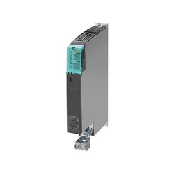
| Product Description | SINAMICS S120 SINGLE MOTOR MODULE INPUT: DC 600V OUTPUT: 3-PH 400V, 9A FRAME SIZE: BOOKSIZE D-TYPE INTERNAL AIR COOLING OPTIMIZED PULSE SAMPLE AND SUPPORT OF THE EXTENDED SAFETY INTEGRATED FUNCTIONS INCL. DRIVE-CLIQ CABLE |
| Product family | Ordering Data Overview |
| Product Lifecycle (PLM) | PM300:Active Product |
| Additional Product Information | |
| EAN | 4034106439606 |
| UPC | 804766208232 |
| Commodity Code | 85044085 |
| LKZ_FDB/ CatalogID | D21MC |
| Product Group | 9617 |
| Group Code | R220 |
| Country of origin | Germany |
| SCIP number | Not available |
| Delivery information | |
| Net Weight (lb) | 10.141 lb |
| Package size unit of measure | Not available |
| Packaging Quantity | 1 |
| Product | |
| Article Number (Market Facing Number) | 6SL32101KE226AF1 | 6SL32101KE226AF1 |
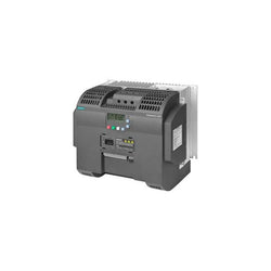
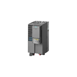
| Product Description | SINAMICS g120c rated power 11,0 150% overload for 3 sec 3AC380- +10/-20% 47-63HZ integrated fil a i/o-interface 6di, 2do,1ai,1a torque off integrated fieldbus PROFINET-pn protection IP20/ ul type size fsc 295x140x203(hxwxd external 24v |
| Product family | Ordering Data Overview |
| Product Lifecycle (PLM) | PM300:Active Product |
| Additional Product Information | |
| EAN | 4042948663868 |
| UPC | 887621077860 |
| Commodity Code | 85044095 |
| LKZ_FDB/ CatalogID | D11.1SD |
| Product Group | 5673 |
| Group Code | R220 |
| Country of origin | Great Britain |
| SCIP number | Not available |
| Delivery information | |
| Net Weight (lb) | 12.125 lb |
| Package size unit of measure | Inch |
| Packaging Quantity | 1 |
| Product | |
| Article Number (Market Facing Number) | 6SL31000BE216AB0 | 6SL31000BE216AB0 |
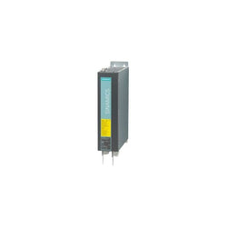
| Product Description | SINAMICS S120 ACTIVE INTERFACE MODULE FOR 16KW ACTIVE LINE MODULE INPUT: 3AC 380-480V, 50/60HZ FRAME SIZE: BOOKSIZE |
| Product family | Ordering Data Overview |
| Product Lifecycle (PLM) | PM300:Active Product |
| Additional Product Information | |
| EAN | 4042948662939 |
| UPC | 662643344943 |
| Commodity Code | 85363030 |
| LKZ_FDB/ CatalogID | D21MC |
| Product Group | 9617 |
| Group Code | R220 |
| Country of origin | Germany |
| SCIP number | Not available |
| Delivery information | |
| Net Weight (lb) | 28.660 lb |
| Package size unit of measure | Not available |
| Packaging Quantity | 1 |

| Product | |
| Article Number (Market Facing Number) | 6SL32101KE232AF1 | 6SL32101KE232AF1 |
| Product Description | SINAMICS G120C rated power 3AC380-480V +10/-20% 47-63Hz low overload: 15,0kW at 150% 3s, 110% 57s, 100% 240s high overload: 11,0kW at 200% 3s, 150% 57s, 100% 240s integrated filter class A external 24V I/O interface: 6DI, 2DO,1AI,1AO, 1Mot_t Safe Torque Off integrated Fieldbus: PROFINET-PN Protection: IP20/ UL OPEN TYPE Size: FSC 295x140x205 (HXWXD) |
| Product family | Ordering Data Overview |
| Product Lifecycle (PLM) | PM300:Active Product |
| Additional Product Information | |
| EAN | 4042948663875 |
| UPC | 887621035693 |
| Commodity Code | 85044095 |
| LKZ_FDB/ CatalogID | D11.1SD |
| Product Group | 5673 |
| Group Code | R220 |
| Country of origin | Great Britain |
| SCIP number | Not available |
| Delivery information | |
| Net Weight (lb) | 12.125 lb |
| Package size unit of measure | Inch |
| Packaging Quantity | 1 |
| Product | |
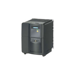
| Article Number (Market Facing Number) | 6SE64402UC240CA1 | 6SE64402UC240CA1 |
| Product Description | |
| Product family | Not available |
| Product Lifecycle (PLM) | PM410:Product cancellation |
| Additional Product Information | |
| EAN | 4019169450201 |
| UPC | 783087635319 |
| Commodity Code | 85044095 |
| LKZ_FDB/ CatalogID | DA51-D |
| Product Group | 9848 |
| Group Code | R2S3 |
| Country of origin | Great Britain |
| SCIP number | Not available |
| Delivery information | |
| Net Weight (lb) | 12.125 lb |
| Package size unit of measure | Inch |
| Packaging Quantity | 1 |

| Product | |
| Article Number (Market Facing Number) | 6GK74431EX300XE0 | 6GK74431EX300XE0 |
| Product Description | Communications processor CP 443-1; 2x 10/100 Mbit/s (IE switch); RJ45 ports; ISO; TCP; UDP; PROFINET IO controller; S7 communication; Open communication (SEND/ RECEIVE); S7 routing; IP configuration via DHCP/ Block; IP Access control list; time-of-day synchronization; extended web diagnostics; Fast Startup; Support for PROFIenergy; |
| Product family | CP 443-1 |
| Product Lifecycle (PLM) | PM300:Active Product |
| Additional Product Information | |
| EAN | 4019169206709 |
| UPC | 040892953275 |
| Commodity Code | 85176200 |
| LKZ_FDB/ CatalogID | IK |
| Product Group | 2414 |
| Group Code | R322 |
| Country of origin | Germany |
| SCIP number | Not available |
| Delivery information | |
| Net Weight (lb) | 1.836 lb |
| Package size unit of measure | Inch |
| Packaging Quantity | 1 |
| Product | |
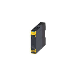
| Article Number (Market Facing Number) | 3SK11111AB30 | 3SK11111AB30 |
| Product Description | |
| Product family | SIRIUS 3SK1 Standard basic units |
| Product Lifecycle (PLM) | PM300:Active Product |
| Additional Product Information | |
| EAN | 4011209913509 |
| UPC | Not available |
| Commodity Code | 85371098 |
| LKZ_FDB/ CatalogID | CC-IC10 |
| Product Group | 3761 |
| Group Code | R711 |
| Country of origin | Germany |
| SCIP number | Not available |
| Delivery information | |
| Net Weight (lb) | 0.573 lb |
| Package size unit of measure | Inch |
| Packaging Quantity | 1 |

| Product | |
| Article Number (Market Facing Number) | 3SE53120SD11 | 3SE53120SD11 |
| Product Description | Safety position switch with tumbler Locking force 2600 N 5 directions of approaches Spring-locked Auxiliary release on front Magnet voltage 24 V DC Monitoring actuator 2 NC/1 NO Monitoring magnet 2 NC/1 NO Supplied without actuator. Actuator 3SE5000-0AV0. please order separately |
| Product family | 3SE5, metal enclosures with locking force greater than 2 000 N |
| Product Lifecycle (PLM) | PM300:Active Product |
| Additional Product Information | |
| EAN | 4011209682955 |
| UPC | Not available |
| Commodity Code | 85365019 |
| LKZ_FDB/ CatalogID | CC-IC10 |
| Product Group | 5317 |
| Group Code | R711 |
| Country of origin | Germany |
| SCIP number | Not available |
| Delivery information | |
| Net Weight (lb) | 2.094 lb |
| Package size unit of measure | in |
| Packaging Quantity | 1 |
SIWAREX U WEIGHING ELECTRONICS (TWO-CHANNEL VERSION) FOR CONNNECTING TWO SCALES FOR SIMATIC S7-300 AND ET200M RS232 INTERFACE FOR CONNECT. OF A PC TTY INTERFACE FOR REMOTE DISPLAY CONNECTION WITH BUS CONNECTOR

| Product | |
| Article Number (Market Facing Number) | 6SL32101PE288UL0 | 6SL32101PE288UL0 |
| Product Description | SINAMICS G120 POWER MODULE PM240-2 WITHOUT FILTER WITH BUILT IN BRAKING CHOPPER 3AC380-480V +10/-20% 47-63HZ OUTPUT HIGH OVERLOAD: 37KW FOR 200% 3S,150% 57S,100% 240S AMBIENT TEMP -20 TO +50 DEG C (HO) OUTPUT LOW OVERLOAD: 45kW FOR 150% 3S,110% 57S,100% 240S AMBIENT TEMP -20 TO +40 DEG C (LO) 551 X 275 X 237 (HXWXD), FSE PROTECTION IP20 WITHOUT CONTROL UNIT AND PANEL APPROVED FOR CU FIRMWARE- VERSION V4.7 HF8 |
| Product family | Ordering Data Overview |
| Product Lifecycle (PLM) | PM300:Active Product |
| Additional Product Information | |
| EAN | 4042948668108 |
| UPC | 804766090899 |
| Commodity Code | 85044095 |
| LKZ_FDB/ CatalogID | D11.1SD |
| Product Group | 9775 |
| Group Code | R220 |
| Country of origin | Germany |
| SCIP number | Not available |
| Delivery information | |
| Net Weight (lb) | 58.202 lb |
| Package size unit of measure | Inch |
| Packaging Quantity | 1 |

| Product | |
| Article Number (Market Facing Number) | 6GT28012BA10 | 6GT28012BA10 |
| Product Description | SIMATIC RF300; Reader RF340R (GEN2); RS422 interface (3964R); IP67, -25 to +70 °C, 75x 75x 41 mm with integrated antenna . |
| Product family | RF340R |
| Product Lifecycle (PLM) | PM300:Active Product |
| Additional Product Information | |
| EAN | 4047622417959 |
| UPC | 804766348686 |
| Commodity Code | 84719000 |
| LKZ_FDB/ CatalogID | ID10.M |
| Product Group | 9471 |
| Group Code | R322 |
| Country of origin | Germany |
| SCIP number | Not available |
| Delivery information | |
| Net Weight (lb) | 0.661 lb |
| Package size unit of measure | Inch |
| Packaging Quantity | 1 |

| Product | |
| Article Number (Market Facing Number) | 6ES79720AA020XA0 | 6ES79720AA020XA0 |
| Product Description | SIMATIC DP, RS485 repeater For connection of PROFIBUS/MPI bus systems with max. 31 nodes max. baud rate 12 Mbit/s, Degree of protection IP20 Improved user handling |
| Product family | RS 485 repeater for PROFIBUS |
| Product Lifecycle (PLM) | PM400:Announcement of product phase-out |
| Additional Product Information | |
| EAN | 4025515079620 |
| UPC | 040892595581 |
| Commodity Code | 85176200 |
| LKZ_FDB/ CatalogID | ST76 |
| Product Group | X08V |
| Group Code | R151 |
| Country of origin | Germany |
| SCIP number | Not available |
| Delivery information | |
| Net Weight (lb) | 0.538 lb |
| Package size unit of measure | Inch |
| Packaging Quantity | 1 |
| Product | |
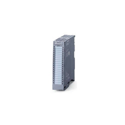
| Article Number (Market Facing Number) | 6ES75221BH010AB0 | 6ES75221BH010AB0 |
| Product Description | SIMATIC S7-1500, digital output module DQ16x24 V DC/0.5A HF; 16 channels in groups of 8; 4 A per group; single-channel diagnostics; substitute value: switching cycle counter for connected actuators. the module supports the safety-oriented shutdown of load groups up to SIL2 according to EN IEC 62061:2021 and Category 3 / PL d according to EN ISO 13849-1:2015. front connector (screw terminals or push-in) to be ordered separately |
| Product family | SM 522 digital output modules |
| Product Lifecycle (PLM) | PM300:Active Product |
| Additional Product Information | |
| EAN | 4047623405931 |
| UPC | 804766234163 |
| Commodity Code | 85389091 |
| LKZ_FDB/ CatalogID | ST73 |
| Product Group | 4501 |
| Group Code | R151 |
| Country of origin | Germany |
| SCIP number | Not available |
| Delivery information | |
| Net Weight (lb) | 0.604 lb |
| Package size unit of measure | Inch |
| Packaging Quantity | 1 |
| Product | |
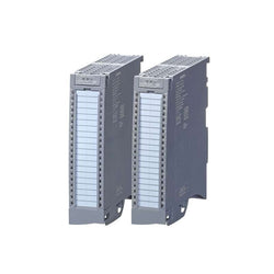
| Article Number (Market Facing Number) | 6ES75221BL010AB0 | 6ES75221BL010AB0 |
| Product Description | SIMATIC S7-1500, digital output module DQ 32x24V DC/0.5A HF; 32 channels in groups of 8; 4 A per group; single-channel diagnostics; substitute value, switching cycle counter for connected actuators. the module supports the safety-oriented shutdown of load groups up to SIL2 according to EN IEC 62061:2021 and Category 3 / PL d according to EN ISO 13849-1:2015. front connector (screw terminals or push-in) to be ordered separately |
| Product family | SM 522 digital output modules |
| Product Lifecycle (PLM) | PM300:Active Product |
| Additional Product Information | |
| EAN | 4047623405924 |
| UPC | 804766234446 |
| Commodity Code | 85389091 |
| LKZ_FDB/ CatalogID | ST73 |
| Product Group | 4501 |
| Group Code | R151 |
| Country of origin | Germany |
| SCIP number | Not available |
| Delivery information | |
| Net Weight (lb) | 0.708 lb |
| Package size unit of measure | Inch |
| Packaging Quantity | 1 |
| Product | |
| Article Number (Market Facing Number) | 6ES72231PH320XB0 | 6ES72231PH320XB0 |
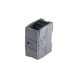
| Product Description | SIMATIC S7-1200, Digital I/O SM 1223, 8 DI/8 DO, 8 DI 24 V DC, Sink/Source, 8 DO, relay 2 A |
| Product family | SM 1223 digital input/output modules |
| Product Lifecycle (PLM) | PM300:Active Product |
| Additional Product Information | |
| EAN | 6940408101999 |
| UPC | 887621175320 |
| Commodity Code | 85389091 |
| LKZ_FDB/ CatalogID | ST72 |
| Product Group | 4508 |
| Group Code | R132 |
| Country of origin | Germany |
| SCIP number | Not available |
| Delivery information | |
| Net Weight (lb) | 0.481 lb |
| Package size unit of measure | Inch |
| Packaging Quantity | 1 |
| Product | |
| Article Number (Market Facing Number) | 6ES72324HB320XB0 | 6ES72324HB320XB0 |
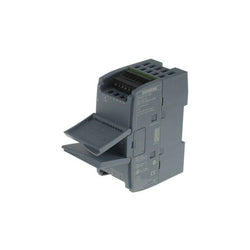
| Product Description | SIMATIC S7-1200, Analog output, SM 1232, 2 AO, +/-10 V, 14-bit resolution, or 0-20 mA/4-20 mA, 13-bit resolution |
| Product family | SM 1232 analog output modules |
| Product Lifecycle (PLM) | PM300:Active Product |
| Additional Product Information | |
| EAN | 6940408102057 |
| UPC | 887621210113 |
| Commodity Code | 85389091 |
| LKZ_FDB/ CatalogID | ST72 |
| Product Group | 4508 |
| Group Code | R132 |
| Country of origin | Germany |
| SCIP number | Not available |
| Delivery information | |
| Net Weight (lb) | 0.328 lb |
| Package size unit of measure | Inch |
| Packaging Quantity | 1 |
| Product | |
| Article Number (Market Facing Number) | 6ES72344HE320XB0 | 6ES72344HE320XB0 |
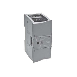
| Product Description | SIMATIC S7-1200, analog I/O SM 1234, 4 AI/2 AO, +/-10 V, 14-bit resolution or 0 (4)-20mA, 13-bit resolution |
| Product family | SM 1234 analog input/output modules |
| Product Lifecycle (PLM) | PM300:Active Product |
| Additional Product Information | |
| EAN | 6940408102071 |
| UPC | 887621217716 |
| Commodity Code | 85389091 |
| LKZ_FDB/ CatalogID | ST72 |
| Product Group | 4508 |
| Group Code | R132 |
| Country of origin | Germany |
| SCIP number | Not available |
| Delivery information | |
| Net Weight (lb) | 0.395 lb |
| Package size unit of measure | Inch |
| Packaging Quantity | 1 |
| Product | |
| Article Number (Market Facing Number) | 6ES73211BH020AA0 | 6ES73211BH020AA0 |
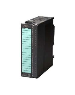
| Product Description | SIMATIC S7-300, Digital input SM 321, isolated, 16 DI, 24 V DC, 1x 20-pole |
| Product family | SM 321 digital input modules |
| Product Lifecycle (PLM) | PM400:Announcement of product phase-out |
| Additional Product Information | |
| EAN | 4025515051893 |
| UPC | 040892561715 |
| Commodity Code | 85389091 |
| LKZ_FDB/ CatalogID | ST73 |
| Product Group | 2288 |
| Group Code | R151 |
| Country of origin | Germany |
| SCIP number | Not available |
| Delivery information | |
| Net Weight (lb) | 0.522 lb |
| Package size unit of measure | Inch |
| Packaging Quantity | 1 |
| Product | |
| Article Number (Market Facing Number) | 6ES73221BH010AA0 | 6ES73221BH010AA0 |
| Product Description | SIMATIC S7-300, Digital output SM 322, isolated, 16 DO, 24 V DC, 0.5A, 1x 20-pole, Total current 4 A/group (8 A/module) |
| Product family | SM 322 digital output modules |
| Product Lifecycle (PLM) | PM400:Announcement of product phase-out |
| Additional Product Information | |
| EAN | 4025515060918 |
| UPC | 040892560640 |
| Commodity Code | 85389091 |
| LKZ_FDB/ CatalogID | ST73 |
| Product Group | 2288 |
| Group Code | R151 |
| Country of origin | Germany |
| SCIP number | Not available |
| Delivery information | |
| Net Weight (lb) | 0.538 lb |
| Package size unit of measure | Inch |
| Packaging Quantity | 1 |