
 1 year warranty


PLC Direct is not an authorized distributor. We offer a broad range of in-stock products with minimal lead time.

TeSys LRD thermal overload relays - 37...50 A - class 10A

compact base - 42 I/O - 24 V DC supply

TeSys F contactor, 3 poles (3NO), 225A/690V AC-3, for motor applications up to 110kW@400V. It provides a low sealed consumption 220V 40-400Hz AC coil, bolt terminals for bars or cables with lugs. For high operating rates until 2400 cycles/hour and environments until 55°C, it procures high reliability and durability. It makes installation and maintenance easy thanks to its drawer-mounted coil and a large choice of add-on blocks and accessories (to be ordered separately). Multi standards certified (IEC, UL, CSA, CCC, EAC, Marine), Green Premium compliant (RoHS/REACh).
Main
| Characteristic | Value(s) |
|---|---|
| Range | TeSys |
| Range of Product | TeSys F |
| Product or Component Type | Contactor |
| Device short name | LC1F |
| Contactor application | Motor control Resistive load |
| Utilisation category | AC-1 AC-4 AC-3 |
| Poles description | 3P |
| [Ue] rated operational voltage | <= 460 V DC <= 690 V AC 50/60 Hz |
| [Uc] control circuit voltage | 220 V AC 40...400 Hz |
| [Ie] rated operational current | 315 A (at <104 °F (40 °C)) at <= 440 V AC-1 225 A (at <131 °F (55 °C)) at <= 440 V AC-3 |
Complementary
| Characteristic | Value(s) |
|---|---|
| [Uimp] rated impulse withstand voltage | 8 kV |
| [Ith] conventional free air thermal current | 315 A (at 104 °F (40 °C)) |
| Rated breaking capacity | 1800 A conforming to IEC 60947-4-1 |
| [Icw] rated short-time withstand current | 1800 A 104 °F (40 °C) - 10 s 1000 A 104 °F (40 °C) - 30 s 850 A 104 °F (40 °C) - 1 min 560 A 104 °F (40 °C) - 3 min 440 A 104 °F (40 °C) - 10 min |
| Associated fuse rating | 315 A gG at <= 440 V 250 A aM at <= 440 V |
| Average impedance | 0.32 mOhm - Ith 315 A 50 Hz |
| [Ui] rated insulation voltage | 1000 V IEC 60947-4-1 1500 V VDE 0110 group C |
| Power dissipation per pole | 32 W AC-1 16 W AC-3 |
| Overvoltage category | III |
| power pole contact composition | 3 NO |
| Motor power kW | 110 kW at 380...400 V AC 50/60 Hz (AC-3) 110 kW at 415 V AC 50/60 Hz (AC-3) 110 kW at 440 V AC 50/60 Hz (AC-3) 129 kW at 500 V AC 50/60 Hz (AC-3) 129 kW at 660...690 V AC 50/60 Hz (AC-3) 63 kW at 220...230 V AC 50/60 Hz (AC-3) 40 kW at 400 V AC 50/60 Hz (AC-4) |
| Control circuit voltage limits | Operational 0.85...1.1 Uc 40...400 Hz 131 °F (55 °C)) Drop-out 0.2...0.55 Uc 40...400 Hz 131 °F (55 °C)) |
| Mechanical durability | 10 Mcycles |
| Inrush power in VA | 1070 VA, 40...400 Hz 0.9 68 °F (20 °C)) |
| Hold-in power consumption in VA | 9.9 VA, 40...400 Hz 0.9 68 °F (20 °C)) |
| Maximum operating rate | 2400 cyc/h 131 °F (55 °C) |
| Operating time | 35 ms closing at Uc) 130 ms opening at Uc) |
| Connections - terminals | Control circuit screw clamp terminals 1 0.002â¦0.006 in² (1â¦4 mm²)flexible without cable end Control circuit screw clamp terminals 2 0.002â¦0.006 in² (1â¦4 mm²)flexible without cable end Control circuit screw clamp terminals 1 0.002â¦0.006 in² (1â¦4 mm²)flexible with cable end Control circuit screw clamp terminals 2 0.002â¦0.004 in² (1â¦2.5 mm²)flexible with cable end Control circuit screw clamp terminals 1 0.002â¦0.006 in² (1â¦4 mm²)solid without cable end Control circuit screw clamp terminals 2 0.002â¦0.006 in² (1â¦4 mm²)solid without cable end Power circuit bar 2 32 x 4 mm Power circuit lugs-ring terminals 1 0.3 in² (185 mm²) Power circuit connector 1 0.3 in² (185 mm²) Power circuit bolted connection |
| Tightening torque | Control circuit 10.6 lbf.in (1.2 N.m) Power circuit 309.8 lbf.in (35 N.m) |
| Mounting Support | Plate |
| Heat dissipation | 8â¦9.8 W |
| motor power range | 55â¦100 kW 200â¦240 V 3 phase 110â¦220 kW 480â¦500 V 3 phase 110â¦220 kW 380â¦440 V 3 phase |
| Motor starter type | Direct on-line contactor |
| Contactor coil voltage | 220 V AC standard |
| Standards | IEC 60947-1 JIS C8201-4-1 EN 60947-1 IEC 60947-4-1 EN 60947-4-1 |
| Product Certifications | RINA BV CSA UL LROS (Lloyds register of shipping) DNV RMRoS ABS CB UKCA |
| Compatibility code | LC1F |
| Control circuit type | AC 40...400 Hz |

This product is part of the PacDrive 3 range, an offer of connection accessories. This connection module features SERCOS III interface. It is an integrated servo motor with a supply voltage of 250V to 700V and an input current of 20A. It is an IP20 rated product. Its dimensions are 44.5mm (width) x 270mm (depth) x 310mm (height). It weighs 3kg. It is suitable for use in general machine control, packaging machine automation, material handling applications. It supports natural convection cooling system. Lexium 62 ILM integrated servo modules can be controlled with all PacDrive LMC Eco and Pro/Pro 2 series motion controllers via SERCOS communication. Multiaxis integrated servo drives from 0.31kW to 1.91kW for automation solutions based on PacDrive 3.
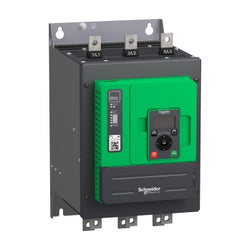
Altivar Soft Starter ATS480 is intended to start and stop asynchronous motors supplied from 208V to 690V. It meets the requirements of the most demanding applications in normal and heavy duty. With an operational rated current of 140A in normal duty, it supplies motor from 37kW to 110kW according to mains voltage. Designed for digitization, connected, optimized to meet cybersecurity standard, it simplifies project execution and maximizes the availability of applications. Its torque control (TCS) masters acceleration and deceleration. It efficiently stops high inertia application thanks to the dynamic braking and DC injection. It could be connected in-line or inside the delta to reduce its operational current. The embedded test routine simplifies the commissioning inside the delta. Its dimensions are 200mm (width) x 272mm (depth) x 340mm (height) and it weighs 12,4kg. Altivar Soft Starter ATS480 is designed to address process, infrastructures and industrial machines. It conforms to IEC/EN60947-4-1. It is certified CE, cULus, UKCA, CCC, RCM, EAC, and Marine certified DNV, ABS, BV and CCS. Display terminals, remote mounting kit, communication modules are common with Altivar Drives. Line chokes, DNV kits are common with ATS48. ATS480 is compatible with ATS48, it has same footprint, fixing, torque control algorithm, I/O, menus⦠The integration of Altivar Soft Starter ATS480 in EcoStruxure drastically simplifies architecture selection, detailed design and execution in automation and electrical systems.
Main
| Characteristic | Value(s) |
|---|---|
| Range of Product | Altivar Soft Starter ATS480 |
| Product or Component Type | Soft starter |
| Product destination | Asynchronous motors |
| Product Specific Application | Process and infrastructures |
| Device short name | ATS480 |
| Phase | 3 phase |
| Utilisation category | AC-3A AC-53A |
| Ue power supply voltage | 208...690 V - 15...10 % |
| power supply frequency | 50...60 Hz - 20...20 % |
| [Ie] rated operational current | Normal duty 140.0 A 104 °F (40 °C)) |
| rated current in heavy duty | 110.0 A at 104 °F (40 °C) heavy duty |
| Torque control | True |
| IP Degree of Protection | IP00 |
| Motor power kW | 37.0 kW 230 V in the motor supply line normal duty 30.0 kW 230 V in the motor supply line heavy duty 75.0 kW 400 V in the motor supply line normal duty 55.0 kW 400 V in the motor supply line heavy duty 75.0 kW 440 V in the motor supply line normal duty 55.0 kW 440 V in the motor supply line heavy duty 90.0 kW 500 V in the motor supply line normal duty 75.0 kW 500 V in the motor supply line heavy duty 90.0 kW 525 V in the motor supply line normal duty 75.0 kW 525 V in the motor supply line heavy duty 110.0 kW 660 V in the motor supply line normal duty 90.0 kW 660 V in the motor supply line heavy duty 110.0 kW 690 V in the motor supply line normal duty 90.0 kW 690 V in the motor supply line heavy duty 75.0 kW 230 V to the motor delta terminals normal duty 55.0 kW 230 V to the motor delta terminals heavy duty 110.0 kW 400 V to the motor delta terminals normal duty 90.0 kW 400 V to the motor delta terminals heavy duty |
| Maximum Horse Power Rating | 40.0 hp 208 V normal duty 30.0 hp 208 V heavy duty 50.0 hp 230 V normal duty 40.0 hp 230 V heavy duty 100.0 hp 460 V normal duty 75.0 hp 460 V heavy duty 125.0 hp 575 V normal duty 100.0 hp 575 V heavy duty |
| Option card | Communication module Profibus DP V1 Communication module Modbus TCP/EtherNet/IP Communication module CANopen daisy chain Communication module CANopen Sub-D Communication module CANopen open style Communication module PROFINET |
Complementary
| Characteristic | Value(s) |
|---|---|
| Device connection | In the motor supply line To the motor delta terminals |
| [Us] control circuit voltage | 110...230 V AC 50/60 Hz - 15...10 % |
| Apparent power | 0.09 kVA |
| Integrated motor overload protection | True |
| motor thermal protection class | Class 10E |
| Protection type | Phase failure line Integrated thermal protection motor Thermal protection starter Current overload motor Underload motor Excessive starting time, locked rotor motor Motor phase loss motor Line supply phase loss line Line supply phase loss motor Thermal protection motor |
| current limiting %In (5 x Ie maximum) | 150â¦700 % |
| [In] Rated current pwr loss specifctn | 140.0 A |
| Power loss static current independent | 25.0 W |
| Power loss per device current dependent | 366.0 W |
| Standards | IEC 60947-4-2 UL 60947-4-2 IEC 60664-1 |
| Product Certifications | CE cULus CCC UKCA RCM EAC DNV ABS BV CCS |
| Marking | CE CCC UKCA EAC RCM CULus |
| [Uc] control circuit voltage | 24 V DC |
| Discrete input number | 4 |
| Discrete input type | STOP) logic inputs, 3500 Ohm RUN) logic inputs, 3500 Ohm DI3) programmable as logic input, 3500 Ohm DI4) programmable as logic input, 3500 Ohm |
| Input compatibility | STOP discrete input level 1 PLC IEC 61131-2 RUN discrete input level 1 PLC IEC 61131-2 DI3 discrete input level 1 PLC IEC 61131-2 DI4 discrete input level 1 PLC IEC 61131-2 |
| Discrete input logic | Programmable digital input < 5 V |
| Relay output number | 3 |
| Relay output type | Relay outputs R1A 1 NO Relay outputs R1B 1 NO Relay outputs RIC NO/NC programmable |
| Minimum switching current | 100 mA 12 V DC relay outputs |
| Maximum switching current | Relay outputs 2 A 250 V AC Relay outputs 2 A 30 V DC Relay outputs |
| Discrete output number | 2 |
| Discrete output type | DQ1) programmable digital output <= 30 V DQ2) programmable digital output <= 30 V |
| Output compatibility | Open collector level 1 PLC IEC 65A-68 |
| Analogue input number | 1 |
| Analogue input type | AI1/PTC PTC/Pt 100 temperature probe PTC2 PTC/Pt 100 temperature probe PTC3 PTC/Pt 100 temperature probe |
| Analogue output number | 1 |
| Analogue output type | Current output AQ1 0...20 mA or 0...10 V 500 Ohm |
| Communication Port Protocol | Modbus serial |
| Connector Type | 1 RJ45 |
| Communication data link | Serial |
| Physical interface | 2-wire RS 485 |
| Transmission Rate | 1200...256000 bit/s |
| Transmission frame | RTU |
| Data format | 8 bits, configurable odd, even or no parity |
| Type of polarization | No impedance Modbus serial |
| Number of addresses | 0â¦227 Modbus serial |
| Method of access | Slave Modbus serial |
| Function Available | External bypass control Pre-heating Smoke extraction Multi-motor cascade Second motor set User management Ports and services hardening Security event logging Cybersecure firmware update Single direction |
| Display screen available | True |
| Operating position | Vertical +/- 10 degree |
| Height | 13.4 in (340.0 mm) |
| Width | 7.9 in (200.0 mm) |
| Depth | 10.7 in (272.0 mm) |
| Product Weight | 27.3 lb(US) (12.4 kg) |

Altivar Soft Starter Ats480 Is Intended To Start And Stop Asynchronous Motors Supplied From 208V To 690V. It Meets The Requirements Of The Most Demanding Applications In Normal And Heavy Duty. With An Operational Rated Current Of 32A In Normal Duty, It Supplies Motor From 7,5Kw To 22Kw According To Mains Voltage. Designed For Digitization, Connected, Optimized To Meet Cybersecurity Standard, It Simplifies Project Execution And Maximizes The Availability Of Applications. Its Torque Control (Tcs) Masters Acceleration And Deceleration. It Efficiently Stops High Inertia Application Thanks To The Dynamic Braking And Dc Injection. It Could Be Connected In-Line Or Inside The Delta To Reduce Its Operational Current. The Embedded Test Routine Simplifies The Commissioning Inside The Delta. Its Dimensions Are 160Mm (Width) X 203Mm (Depth) X 275Mm (Height) And It Weighs 4,9Kg. Altivar Soft Starter Ats480 Is Designed To Address Process, Infrastructures And Industrial Machines. It Conforms To Iec/En60947-4-1. It Is Certified Ce, Culus, Ukca, Ccc, Rcm, Eac, And Marine Certified Dnv, Abs, Bv And Ccs. Display Terminals, Remote Mounting Kit, Communication Modules Are Common With Altivar Drives. Line Chokes, Dnv Kits Are Common With Ats48. Ats480 Is Compatible With Ats48, It Has Same Footprint, Fixing, Torque Control Algorithm, I/O, Menus… The Integration Of Altivar Soft Starter Ats480 In Ecostruxure Drastically Simplifies Architecture Selection, Detailed Design And Execution In Automation And Electrical Systems. It Is A Green Premium Product Designed To Take The Environmental Considerations Beyond Current Directives And Regulations, Compliant With Rohs And Reach.

The GV3 manual starter and protector provides manual isolation, manual motor control, and thermal overcurrent protection in one compact unit. The basic motor starter GV3PE controls motors with full load currents up to 65 amperes. The manual starter is three pole with horsepower ratings. The manual starter is operated by a rotary handle. The Class 10 ambient compensated thermal over current is adjustable from 30 ampere to 40 ampere. This device has EVERLINK terminals. Multi standards certified (IEC, UL, CSA, CCC, EAC, Marine, ATEX).
Main
| Characteristic | Value(s) |
|---|---|
| Range | TeSys Deca |
| product name | TeSys GV3 |
| Product or Component Type | Motor circuit breaker |
| Device short name | GV3P |
| Device Application | Motor protection |
| Trip unit technology | Thermal-magnetic |
Complementary
| Characteristic | Value(s) |
|---|---|
| Poles description | 3P |
| Network type | AC |
| Utilisation category | Category A IEC 60947-2 AC-3 IEC 60947-4-1 |
| Network frequency | 50/60 Hz IEC 60947-2 |
| Motor power kW | 18.5 kW 400/415 V AC 50/60 Hz 22 kW 500 V AC 50/60 Hz 37 kW 690 V AC 50/60 Hz |
| Breaking capacity | 100 kA Icu 230/240 V AC 50/60 Hz IEC 60947-2 50 kA Icu 400/415 V AC 50/60 Hz IEC 60947-2 50 kA Icu 440 V AC 50/60 Hz IEC 60947-2 12 kA Icu 500 V AC 50/60 Hz IEC 60947-2 6 kA Icu 690 V AC 50/60 Hz IEC 60947-2 |
| [Ics] rated service short-circuit breaking capacity | 100 % 230/240 V AC 50/60 Hz IEC 60947-2 100 % 400/415 V AC 50/60 Hz IEC 60947-2 100 % 440 V AC 50/60 Hz IEC 60947-2 50 % 500 V AC 50/60 Hz IEC 60947-2 50 % 690 V AC 50/60 Hz IEC 60947-2 |
| Control Type | Rotary handle |
| Line Rated Current | 40 A |
| Thermal protection adjustment range | 30â¦40 A IEC 60947-2 |
| Magnetic tripping current | 560 A |
| [Ith] conventional free air thermal current | 40 A IEC 60947-2 |
| [Ue] rated operational voltage | 690 V AC 50/60 Hz IEC 60947-2 |
| [Ui] rated insulation voltage | 690 V AC 50/60 Hz IEC 60947-2 |
| [Uimp] rated impulse withstand voltage | 6 kV IEC 60947-2 |
| Phase failure sensitivity | Yes IEC 60947-4-1 |
| Suitability for isolation | Yes IEC 60947-1 |
| Power dissipation per pole | 8 W |
| Mechanical durability | 50000 cycles |
| Electrical durability | 50000 cycles AC-3 415 V In |
| Rated duty | Uninterrupted IEC 60947-4-1 |
| Tightening torque | 44.3 lbf.in (5 N.m) screw clamp terminal |
| Fixing mode | 35 mm symmetrical DIN rail clipped Panel screwed with 3 x M4 screws) |
| Mounting position | Horizontal Vertical |
| Width | 2.2 in (55 mm) |
| Height | 5.2 in (132 mm) |
| Depth | 5.4 in (136 mm) |
| Product Weight | 2.12 lb(US) (0.96 kg) |
| color | Dark grey |

Motor circuit breaker, TeSys GV2, 3P, 13-18 A, thermal magnetic, screw clamp terminals

Motor circuit breaker, TeSys GV2, 3P, 2.5-4 A, thermal magnetic, screw clamp terminals

TeSys F contactor, 3 poles (3NO), 115A/690V AC-3, for motor applications up to 55kW@400V. Contactor with no coil to allow a later selection and installation (coil to be ordered separately), it provides bolt terminals for bars or cables with lugs. For high operating rates until 2400 cycles/hour and environments until 55°C, it procures high reliability and durability. It makes installation and maintenance easy thanks to a drawer for insertion of the selected coil and a large choice of add-on blocks and accessories (to be ordered separately). Multi standards certified (IEC, UL, CSA, CCC, EAC, Marine), Green Premium compliant (RoHS/REACh).
Main
| Characteristic | Value(s) |
|---|---|
| Range | TeSys |
| product name | TeSys F |
| Product or Component Type | Contactor |
| Device short name | LC1F |
| Contactor application | Resistive load Motor control |
| Utilisation category | AC-1 AC-4 AC-3 |
| Poles description | 3P |
| power pole contact composition | 3 NO |
| [Ue] rated operational voltage | <= 690 V AC 50/60 Hz <= 460 V DC |
| [Ie] rated operational current | 200 A 104 °F (40 °C)) <= 440 V AC-1 115 A 131 °F (55 °C)) <= 440 V AC-3 |
| Motor power kW | 55 kW at 380...400 V AC 50/60 Hz (AC-3) 59 kW at 415 V AC 50/60 Hz (AC-3) 59 kW at 440 V AC 50/60 Hz (AC-3) 75 kW at 500 V AC 50/60 Hz (AC-3) 30 kW at 220...240 V AC 50/60 Hz (AC-3) 80 kW at 660...690 V AC 50/60 Hz (AC-3) 18.5 kW at 400 V AC 50/60 Hz (AC-4) |
Complementary
| Characteristic | Value(s) |
|---|---|
| [Uc] control circuit voltage | 24...575 V AC 40...400 Hz with LX9 coil 24...460 V DC with LX4 coil 100...250 V AC 50/60 Hz with LXE coil 100...380 V DC with LXE coil |
| [Uimp] rated impulse withstand voltage | 8 kV |
| Overvoltage category | III |
| [Ith] conventional free air thermal current | 200 A (at 104 °F (40 °C)) |
| Irms rated making capacity | 1150 A conforming to IEC 60947-4-1 |
| Rated breaking capacity | 920 A conforming to IEC 60947-4-1 |
| [Icw] rated short-time withstand current | 1100 A 104 °F (40 °C) - 10 s 640 A 104 °F (40 °C) - 30 s 520 A 104 °F (40 °C) - 1 min 400 A 104 °F (40 °C) - 3 min 320 A 104 °F (40 °C) - 10 min |
| Associated fuse rating | 125 A aM at <= 440 V 200 A gG at <= 440 V |
| Average impedance | 0.37 mOhm - Ith 200 A 50 Hz |
| [Ui] rated insulation voltage | 1000 V IEC 60947-4-1 1500 V VDE 0110 group C |
| Power dissipation per pole | 15 W AC-1 5 W AC-3 |
| Control circuit voltage limits | Operational: 0.85...1.1 Uc AC 40...400 Hz with LX9 coil Drop-out: 0.2...0.55 Uc AC 40...400 Hz with LX9 coil Operational: 0.85...1.1 Uc DC with LX4 coil Drop-out: 0.15...0.2 Uc DC with LX4 coil Operational: 85...275 V AC 50/60 Hz with LXE coil Drop-out: 0...60 V AC 50/60 Hz with LXE coil Operational: 85...418 V DC with LXE coil Drop-out: 0...45 V DC with LXE coil |
| Heat dissipation | 5.9â¦7.2 W 2.2â¦5.5 W |
| Operating time | 35 ms closing with LX9 coil 130 ms opening with LX9 coil 30...40 ms closing with LX4 coil 30...50 ms opening with LX4 coil 40...80 ms closing with LXE coil 6...54 ms opening with LXE coil |
| Mounting Support | Plate |
| Standards | EN 60947-1 JIS C8201-4-1 IEC 60947-4-1 EN 60947-4-1 IEC 60947-1 |
| Product Certifications | RINA ABS CSA DNV RMRoS BV LROS (Lloyds register of shipping) UL CB UKCA |
| Connections - terminals | Power circuit lugs-ring terminals 1 0.1 in² (95 mm²) Power circuit connector 1 0.1 in² (95 mm²) Power circuit bar 2 20 x 3 mm Power circuit bolted connection Control circuit screw clamp terminals 1 0.002â¦0.006 in² (1â¦4 mm²)flexible without cable end Control circuit screw clamp terminals 2 0.002â¦0.006 in² (1â¦4 mm²)flexible with cable end Control circuit screw clamp terminals 1 0.002â¦0.006 in² (1â¦4 mm²)flexible with cable end Control circuit screw clamp terminals 2 0.002â¦0.004 in² (1â¦2.5 mm²)solid without cable end Control circuit screw clamp terminals 1 0.002â¦0.006 in² (1â¦4 mm²) Control circuit screw clamp terminals 2 0.002â¦0.006 in² (1â¦4 mm²) Control circuit screw clamp terminals 1.0 0.0003â¦0.004 in² (0.2â¦2.5 mm²)flexible without cable end Control circuit screw clamp terminals 1.0 0.0004â¦0.004 in² (0.25â¦2.5 mm²)flexible with cable end Control circuit screw clamp terminals 1.0 0.0003â¦0.004 in² (0.2â¦2.5 mm²)solid without cable end |
| Tightening torque | Power circuit 88.5 lbf.in (10 N.m) Control circuit 10.6 lbf.in (1.2 N.m) Control circuit 5.3 lbf.in (0.6 N.m) |
| Mechanical durability | 10 Mcycles |
| Inrush power in VA | 590â¦855 VA, 40...400 Hz cos phi 0.9 (at 68 °F (20 °C))with LX9 coil 543â¦665 VA (at 68 °F (20 °C))with LX4 coil 280â¦310 VA, 50/60 Hz cos phi 0.5 (at 68 °F (20 °C))with LXE coil 270â¦320 VA (at 68 °F (20 °C))with LXE coil |
| Hold-in power consumption in VA | 6.6â¦8.1 VA, 40...400 Hz cos phi 0.9 (at 68 °F (20 °C))with LX9 coil 3.94â¦4.83 VA (at 68 °F (20 °C))with LX4 coil 4.5â¦7.0 VA, 50/60 Hz cos phi 0.5 (at 68 °F (20 °C))with LXE coil 2.5â¦4.0 VA (at 68 °F (20 °C))with LXE coil |
| Maximum operating rate | 2400 cyc/h 131 °F (55 °C) |
| Compatibility code | LC1F |
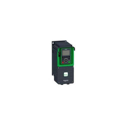
This Altivar Process ATV600 variable speed drive can feed 3-phase synchronous and asynchronous power motors. It features 3 built-in RJ45 communication ports as standard, 1 Ethernet port, 2 serial ports. It works at a rated supply voltage from 380V to 480V AC. This drive provides up to 30% energy saving when on standby due to the innovative ââStop and Goââoperation without additional costs. It is suitable for motors with power rating up to 4kW / 5hp for applications requiring slight overload (up to 120%). It is suitable for motors with power rating up to 3kW / 4hp for applications requiring significant overload (up to 150%). It weighs 4.6kg and its dimensions are, 144mm wide, 350mm high, 203mm deep. This drive is focused on fluids management processing and energy saving, it offers extensive flexibility in water and wastewater, mining, minerals and metals, oil and gas and food and beverage applications. Accessories (fan kit, graphic display terminal) and options (I/O expansion modules, communication modules, EMC input filters) are available with Altivar Process ATV600 drives, depending on the drive rating. It is designed to be mounted in vertical position (+/- 10 °) on a wall. This new concept of drives meets the major needs of process and utilities in terms of equipment efficiency and total cost of ownership by supporting the energy management, asset management and also the overall performance of the process.
Main
| Characteristic | Value(s) |
|---|---|
| Range of Product | Altivar Process ATV600 |
| Product Specific Application | Process and utilities |
| Product or Component Type | Variable speed drive |
| Variant | Standard version |
| Device short name | ATV630 |
| Mounting Mode | Wall mount |
| Communication Port Protocol | Ethernet Modbus serial Modbus TCP |
| [Us] rated supply voltage | 380...480 V - 15...10 % |
| [Us] rated supply voltage | 380...480 V |
| Relative symmetric mains voltage tolerance | 10 % |
| Relative symmetric network frequency tolerance | 5 % |
| nominal output current | 9.3 A |
| IP degree of protection | IP21 |
| Product destination | Asynchronous motors Synchronous motors |
| EMC filter | Integrated 164.04 ft (50 m) IEC 61800-3 category C2 Integrated 492.1 ft (150 m) IEC 61800-3 category C3 |
| IP degree of protection | IP21IEC 61800-5-1 IP21IEC 60529 |
| Degree of protection | UL type 1 UL 508C |
| type of cooling | Forced convection |
| Supply frequency | 50...60 Hz - 5...5 % |
| Motor power kW | 4 kW normal duty) 3 kW heavy duty) |
| Maximum Horse Power Rating | 5 hp normal duty 4 hp heavy duty |
| Line current | 7.6 A 380 V normal duty) 6.7 A 480 V normal duty) 6 A 380 V heavy duty) 5.4 A 480 V heavy duty) |
| Continuous output current | 9.3 A 4 kHz normal duty 7.2 A 4 kHz heavy duty |
| Speed drive output frequency | 0.1â¦500 Hz |
| Safety function | STO (safe torque off) SIL 3 |
| Option card | Slot A communication module, Profibus DP V1 Slot A communication module, PROFINET Slot A communication module, DeviceNet Slot A communication module, Modbus TCP/EtherNet/IP Slot A communication module, CANopen daisy chain RJ45 Slot A communication module, CANopen SUB-D 9 Slot A communication module, CANopen screw terminals Slot A/slot B digital and analog I/O extension module Slot A/slot B output relay extension module Slot A communication module, Ethernet IP/Modbus TCP/MD-Link communication module, BACnet MS/TP communication module, Ethernet Powerlink |
Complementary
| Characteristic | Value(s) |
|---|---|
| Discrete input number | 8 |
| Discrete input type | DI7, DI8 programmable as pulse input 0â¦30 kHz, 24 V DC <= 30 V) |
| Discrete input logic | 16 preset speeds |
| Discrete output number | 0 |
| Discrete output type | Relay outputs R1A, R1B, R1C 250 V AC 3000 mA Relay outputs R1A, R1B, R1C 30 V DC 3000 mA Relay outputs R2A, R2C 250 V AC 5000 mA Relay outputs R2A, R2C 30 V DC 5000 mA Relay outputs R3A, R3C 250 V AC 5000 mA Relay outputs R3A, R3C 30 V DC 5000 mA |
| Analogue input number | 3 |
| Analogue input type | AI1, AI2, AI3 software-configurable voltage 0...10 V DC 31.5 kOhm 12 bits AI1, AI2, AI3 software-configurable current 0...20 mA 250 Ohm 12 bits AI2 voltage analog input - 10...10 V DC 31.5 kOhm 12 bits |
| Analogue output number | 2 |
| Analogue output type | Software-configurable voltage AQ1, AQ2 0...10 V DC 470 Ohm 10 bits Software-configurable current AQ1, AQ2 0...20 mA 10 bits Software-configurable current DQ-, DQ+ 30 V DC Software-configurable current DQ-, DQ+ 100 mA |
| Relay output number | 3 |
| Relay output type | Configurable relay logic R1 fault relay NO/NC 100000 cycles Configurable relay logic R2 sequence relay NO 100000 cycles Configurable relay logic R3 sequence relay NO 100000 cycles |
| Maximum switching current | Relay output R1, R2, R3 resistive, cos phi = 1 3 A 250 V AC Relay output R1, R2, R3 resistive, cos phi = 1 3 A 30 V DC Relay output R1, R2, R3 inductive, cos phi = 0.4 7 ms 2 A 250 V AC Relay output R1, R2, R3 inductive, cos phi = 0.4 7 ms 2 A 30 V DC |
| Minimum switching current | Relay output R1, R2, R3 5 mA 24 V DC |
| Phase | 3 phase |
| Physical interface | Ethernet 2-wire RS 485 |
| Method of access | Slave Modbus TCP |
| Transmission Rate | 10, 100 Mbits 4800 bps, 9600 bps, 19200 bps, 38.4 Kbps |
| Transmission frame | RTU |
| Output voltage | <= power supply voltage |
| Permissible temporary current boost | 1.1 x In 60 s normal duty) 1.5 x In 60 s heavy duty) |
| Data format | 8 bits, configurable odd, even or no parity |
| Type of polarization | No impedance |
| Frequency resolution | Display unit 0.1 Hz Analog input 0.012/50 Hz |
| Electrical connection | Control removable screw terminals 0.5...1.5 mm² AWG 20...AWG 16 Motor screw terminal 2.5...6 mm² AWG 14...AWG 10 Line side screw terminal 2.5...6 mm² AWG 14...AWG 10 |
| Connector type | RJ45 on the remote graphic terminal)Ethernet/Modbus TCP RJ45 on the remote graphic terminal)Modbus serial |
| Exchange mode | Half duplex, full duplex, autonegotiation Ethernet/Modbus TCP |
| Number of addresses | 1â¦247 Modbus serial |
| Supply | External supply for digital inputs 24 V DC 19â¦30 V), <1.25 mA overload and short-circuit protection Internal supply for reference potentiometer (1 to 10 kOhm) 10.5 V DC +/- 5 %, <10 mA overload and short-circuit protection Internal supply for digital inputs and STO 24 V DC 21â¦27 V), <200 mA overload and short-circuit protection |
| Local signalling | 3 LEDs for local diagnostic 3 LEDs (dual colour) for embedded communication status 4 LEDs (dual colour) for communication module status 1 LED (red) for presence of voltage |
| Input compatibility | DI1...DI6 discrete input level 1 PLC IEC 61131-2 DI5, DI6 discrete input level 1 PLC IEC 65A-68 STOA, STOB discrete input level 1 PLC IEC 61131-2 |
| Discrete input logic | Positive logic (source) DI1...DI8), < 5 V, > 11 V Negative logic (sink) DI1...DI8), > 16 V, < 10 V |
| Sampling duration | 2 ms +/- 0.5 ms DI1...DI4) - discrete input 5 ms +/- 1 ms DI5, DI6) - discrete input 5 ms +/- 0.1 ms AI1, AI2, AI3) - analog input 10 ms +/- 1 ms AO1) - analog output |
| Accuracy | +/- 0.6 % AI1, AI2, AI3 for a temperature variation 60 °C analog input +/- 1 % AO1, AO2 for a temperature variation 60 °C analog output |
| Linearity error | AI1, AI2, AI3 +/- 0.15 % of maximum value analog input AO1, AO2 +/- 0.2 % analog output |
| Refresh time | Relay output R1, R2, R3)5 ms +/- 0.5 ms) |
| Isolation | Between power and control terminals |
| Discrete and process manufacturing | Building - HVAC compressor centrifugal Food and beverage processing other application Mining mineral and metal fan Mining mineral and metal pump Oil and gas fan Water and waste water other application Building - HVAC screw compressor Food and beverage processing pump Food and beverage processing fan Food and beverage processing atomization Oil and gas electro submersible pump (ESP) Oil and gas water injection pump Oil and gas jet fuel pump Oil and gas compressor for refinery Water and waste water centrifuge pump Water and waste water positive displacement pump Water and waste water electro submersible pump (ESP) Water and waste water screw pump Water and waste water lobe compressor Water and waste water screw compressor Water and waste water compressor centrifugal Water and waste water fan Water and waste water conveyor Water and waste water mixer |
| Power range | 4â¦6 kW 380â¦440 V 3 phase 4â¦6 kW 480â¦500 V 3 phase |
| Enclosure mounting | Wall mounted |
| 4 quadrant operation possible | False |
| Asynchronous motor control profile | Variable torque standard Constant torque standard Optimized torque mode |
| Synchronous motor control profile | Permanent magnet motor Synchronous reluctance motor |
| Maximum output frequency | 500 kHz |
| Acceleration and deceleration ramps | Linear adjustable separately from 0.01...9999 s |
| Motor slip compensation | Not available in permanent magnet motor law Adjustable Automatic whatever the load Can be suppressed |
| Switching frequency | 2...12 kHz adjustable 4...12 kHz with derating factor |
| Nominal switching frequency | 4 kHz |
| Braking to standstill | By DC injection |
| Brake chopper integrated | False |
| Maximum Input Current per Phase | 7.6 A |
| Maximum output voltage | 480.0 V |
| Apparent power | 5.6 kVA 480 V normal duty) 4.5 kVA 480 V heavy duty) |
| Maximum transient current | 10.8 A 60 s heavy duty) 10.2 A 60 s normal duty) |
| Network Frequency | 50-60 Hz |
| Prospective line Isc | 50 kA |
| Base load current at high overload | 7.2 A |
| Base load current at low overload | 9.3 A |
| Power dissipation in W | Natural convection 33 W 380 V 4 kHz Forced convection 97 W 380 V 4 kHz |
| With safety function Safely Limited Speed (SLS) | False |
| With safety function Safe brake management (SBC/SBT) | False |
| With safety function Safe Operating Stop (SOS) | False |
| With safety function Safe Position (SP) | False |
| With safety function Safe programmable logic | False |
| With safety function Safe Speed Monitor (SSM) | False |
| With safety function Safe Stop 1 (SS1) | False |
| With sft fct Safe Stop 2 (SS2) | False |
| With safety function Safe torque off (STO) | True |
| With safety function Safely Limited Position (SLP) | False |
| With safety function Safe Direction (SDI) | False |
| Protection type | Thermal protection motor Safe torque off motor Motor phase break motor Thermal protection drive Safe torque off drive Overheating drive Overcurrent between output phases and earth drive Overload of output voltage drive Short-circuit protection drive Motor phase break drive Overvoltages on the DC bus drive Line supply overvoltage drive Line supply undervoltage drive Line supply phase loss drive Overspeed drive Break on the control circuit drive |
| Quantity per Set | 1 |
| Width | 5.7 in (144 mm) |
| Height | 13.8 in (350 mm) |
| Depth | 8.0 in (203 mm) |
| Product Weight | 10.1 lb(US) (4.6 kg) |

Variable Speed Drive ATV630 - 3kW - 380...480V - IP21/UL type 1

Main
| Characteristic | Value(s) |
|---|---|
| Range of Product | Altivar Process ATV600 |
| Product Specific Application | Process and utilities |
| Product or Component Type | Variable speed drive |
| Variant | Standard version |
| Device short name | ATV630 |
| Mounting Mode | Cabinet mount |
| Communication Port Protocol | Ethernet Modbus serial Modbus TCP |
| [Us] rated supply voltage | 380...480 V - 15...10 % |
| [Us] rated supply voltage | 380...480 V |
| Relative symmetric mains voltage tolerance | 10 % |
| Relative symmetric network frequency tolerance | 5 % |
| nominal output current | 31.7 A |
| IP degree of protection | IP21 |
| Product destination | Asynchronous motors Synchronous motors |
| EMC filter | Integrated 32.8 ft (10 m) IEC 61800-3 category C2 Integrated 164.04 ft (50 m) IEC 61800-3 category C3 With EMC plate option |
| IP degree of protection | IP20IEC 61800-5-1 IP20IEC 60529 |
| type of cooling | Forced convection |
| Supply frequency | 50...60 Hz - 5...5 % |
| Motor power kW | 15 kW normal duty) 11 kW heavy duty) |
| Maximum Horse Power Rating | 20 hp normal duty 15 hp heavy duty |
| Line current | 27 A 380 V normal duty) 23.3 A 480 V normal duty) 20.6 A 380 V heavy duty) 18.1 A 480 V heavy duty) |
| Continuous output current | 31.7 A 4 kHz normal duty 23.5 A 4 kHz heavy duty |
| Speed drive output frequency | 0.1â¦500 Hz |
| Safety function | STO (safe torque off) SIL 3 |
| Option card | Slot A communication module, Profibus DP V1 Slot A communication module, PROFINET Slot A communication module, DeviceNet Slot A communication module, Modbus TCP/EtherNet/IP Slot A communication module, CANopen daisy chain RJ45 Slot A communication module, CANopen SUB-D 9 Slot A communication module, CANopen screw terminals Slot A/slot B digital and analog I/O extension module Slot A/slot B output relay extension module Slot A communication module, Ethernet IP/Modbus TCP/MD-Link communication module, BACnet MS/TP communication module, Ethernet Powerlink |
Complementary
| Characteristic | Value(s) |
|---|---|
| Discrete input number | 8 |
| Discrete input type | DI7, DI8 programmable as pulse input 0â¦30 kHz, 24 V DC <= 30 V) |
| Discrete input logic | 16 preset speeds |
| Discrete output number | 0 |
| Discrete output type | Relay outputs R1A, R1B, R1C 250 V AC 3000 mA Relay outputs R1A, R1B, R1C 30 V DC 3000 mA Relay outputs R2A, R2C 250 V AC 5000 mA Relay outputs R2A, R2C 30 V DC 5000 mA Relay outputs R3A, R3C 250 V AC 5000 mA Relay outputs R3A, R3C 30 V DC 5000 mA |
| Analogue input number | 3 |
| Analogue input type | AI1, AI2, AI3 software-configurable voltage 0...10 V DC 31.5 kOhm 12 bits AI1, AI2, AI3 software-configurable current 0...20 mA 250 Ohm 12 bits AI2 voltage analog input - 10...10 V DC 31.5 kOhm 12 bits |
| Analogue output number | 2 |
| Analogue output type | Software-configurable voltage AQ1, AQ2 0...10 V DC 470 Ohm 10 bits Software-configurable current AQ1, AQ2 0...20 mA 10 bits Software-configurable current DQ-, DQ+ 30 V DC Software-configurable current DQ-, DQ+ 100 mA |
| Relay output number | 3 |
| Relay output type | Configurable relay logic R1 fault relay NO/NC 100000 cycles Configurable relay logic R2 sequence relay NO 100000 cycles Configurable relay logic R3 sequence relay NO 100000 cycles |
| Maximum switching current | Relay output R1, R2, R3 resistive, cos phi = 1 3 A 250 V AC Relay output R1, R2, R3 resistive, cos phi = 1 3 A 30 V DC Relay output R1, R2, R3 inductive, cos phi = 0.4 7 ms 2 A 250 V AC Relay output R1, R2, R3 inductive, cos phi = 0.4 7 ms 2 A 30 V DC |
| Minimum switching current | Relay output R1, R2, R3 5 mA 24 V DC |
| Phase | 3 phase |
| Physical interface | Ethernet 2-wire RS 485 |
| Method of access | Slave Modbus TCP |
| Transmission Rate | 10, 100 Mbits 4800 bps, 9600 bps, 19200 bps, 38.4 Kbps |
| Transmission frame | RTU |
| Output voltage | <= power supply voltage |
| Permissible temporary current boost | 1.1 x In 60 s normal duty) 1.5 x In 60 s heavy duty) |
| Data format | 8 bits, configurable odd, even or no parity |
| Type of polarization | No impedance |
| Frequency resolution | Display unit 0.1 Hz Analog input 0.012/50 Hz |
| Electrical connection | Control removable screw terminals 0.5...1.5 mm² AWG 20...AWG 16 Line side screw terminal 10...16 mm² AWG 8...AWG 6 Motor screw terminal 10...16 mm² AWG 8...AWG 6 |
| Connector type | RJ45 on the remote graphic terminal)Ethernet/Modbus TCP RJ45 on the remote graphic terminal)Modbus serial |
| Exchange mode | Half duplex, full duplex, autonegotiation Ethernet/Modbus TCP |
| Number of addresses | 1â¦247 Modbus serial |
| Supply | External supply for digital inputs 24 V DC 19â¦30 V), <1.25 mA overload and short-circuit protection Internal supply for reference potentiometer (1 to 10 kOhm) 10.5 V DC +/- 5 %, <10 mA overload and short-circuit protection Internal supply for digital inputs and STO 24 V DC 21â¦27 V), <200 mA overload and short-circuit protection |
| Local signalling | 3 LEDs for local diagnostic 3 LEDs (dual colour) for embedded communication status 4 LEDs (dual colour) for communication module status 1 LED (red) for presence of voltage |
| Input compatibility | DI1...DI6 discrete input level 1 PLC IEC 61131-2 DI5, DI6 discrete input level 1 PLC IEC 65A-68 STOA, STOB discrete input level 1 PLC IEC 61131-2 |
| Discrete input logic | Positive logic (source) DI1...DI8), < 5 V, > 11 V Negative logic (sink) DI1...DI8), > 16 V, < 10 V |
| Sampling duration | 2 ms +/- 0.5 ms DI1...DI4) - discrete input 5 ms +/- 1 ms DI5, DI6) - discrete input 5 ms +/- 0.1 ms AI1, AI2, AI3) - analog input 10 ms +/- 1 ms AO1) - analog output |
| Accuracy | +/- 0.6 % AI1, AI2, AI3 for a temperature variation 60 °C analog input +/- 1 % AO1, AO2 for a temperature variation 60 °C analog output |
| Linearity error | AI1, AI2, AI3 +/- 0.15 % of maximum value analog input AO1, AO2 +/- 0.2 % analog output |
| Refresh time | Relay output R1, R2, R3)5 ms +/- 0.5 ms) |
| Isolation | Between power and control terminals |
| Variable speed drive application selection | Building - HVAC compressor centrifugal Food and beverage processing other application Mining mineral and metal fan Mining mineral and metal pump Oil and gas fan Water and waste water other application Building - HVAC screw compressor Food and beverage processing pump Food and beverage processing fan Food and beverage processing atomization Oil and gas electro submersible pump (ESP) Oil and gas water injection pump Oil and gas jet fuel pump Oil and gas compressor for refinery Water and waste water centrifuge pump Water and waste water positive displacement pump Water and waste water electro submersible pump (ESP) Water and waste water screw pump Water and waste water lobe compressor Water and waste water screw compressor Water and waste water compressor centrifugal Water and waste water fan Water and waste water conveyor Water and waste water mixer |
| Motor power range AC-3 | 15â¦25 kW 380â¦440 V 3 phase 15â¦25 kW 480â¦500 V 3 phase |
| Enclosure mounting | With heat sink |
| 4 quadrant operation possible | False |
| Asynchronous motor control profile | Constant torque standard Variable torque standard Optimized torque mode |
| Synchronous motor control profile | Permanent magnet motor Synchronous reluctance motor |
| Maximum output frequency | 500 kHz |
| Acceleration and deceleration ramps | Linear adjustable separately from 0.01...9999 s |
| Motor slip compensation | Can be suppressed Adjustable Automatic whatever the load Not available in permanent magnet motor law |
| Switching frequency | 2...12 kHz adjustable 4...12 kHz with derating factor |
| Nominal switching frequency | 4 kHz |
| Braking to standstill | By DC injection |
| Brake chopper integrated | False |
| Maximum Input Current per Phase | 27.0 A |
| Maximum output voltage | 480.0 V |
| Apparent power | 19.4 kVA 480 V normal duty) 15 kVA 480 V heavy duty) |
| Maximum transient current | 34.9 A 60 s normal duty) 35.3 A 60 s heavy duty) |
| Network Frequency | 50-60 Hz |
| Prospective line Isc | 50 kA |
| Base load current at high overload | 23.5 A |
| Base load current at low overload | 31.7 A |
| Power dissipation in W | Natural convection 59 W 380 V 4 kHz Forced convection 366 W 380 V 4 kHz |
| With safety function Safely Limited Speed (SLS) | False |
| With safety function Safe brake management (SBC/SBT) | False |
| With safety function Safe Operating Stop (SOS) | False |
| With safety function Safe Position (SP) | False |
| With safety function Safe programmable logic | False |
| With safety function Safe Speed Monitor (SSM) | False |
| With safety function Safe Stop 1 (SS1) | False |
| With sft fct Safe Stop 2 (SS2) | False |
| With safety function Safe torque off (STO) | True |
| With safety function Safely Limited Position (SLP) | False |
| With safety function Safe Direction (SDI) | False |
| Protection type | Thermal protection motor Safe torque off motor Motor phase break motor Thermal protection drive Safe torque off drive Overheating drive Overcurrent between output phases and earth drive Overload of output voltage drive Short-circuit protection drive Motor phase break drive Overvoltages on the DC bus drive Line supply overvoltage drive Line supply undervoltage drive Line supply phase loss drive Overspeed drive Break on the control circuit drive |
| Quantity per Set | 1 |
| Width | 7.7 in (195 mm) |
| Height | 18.9 in (480 mm) |
| Depth | 8.9 in (225.5 mm) |
| Product Weight | 28.7 lb(US) (13 kg) |

Altivar Machine ATV320 range is an offer of variable speed drives designed for Original Equipment Manufacturers (OEMs). Its compact form factor allows vertical stacking of drives inside machine frames It works at a rated power up to 5.5kW / 7.5hp and a rated voltage from 380V to 500V AC. Its robust design with IEC 60721-3-3 class 3C3 coated printed circuit boards allows to extend machine availability in harsh environmental conditions, for example at ambient temperatures of up to 60°C without the need of additional cooling. It incorporates functions suitable for the most common applications, including torque and speed accuracy at very low speed, high dynamic performance with flux vector control without sensor and extended frequency range for high-speed motors. It also incorporates parallel connection of motors and special drives using the voltage/frequency ratio and static speed accuracy and energy saving for open-loop synchronous motors. It weighs 2.2kg and its dimensions are 150mm wide, 232mm high, 172mm deep. Altivar Machine ATV320 meets simple and advanced application requirements covered for packaging, material handling, textile, material working, mechanical actuators and hoisting. It conforms to IEC, UL, TUV, KC and other international standards. Mounting accessories and external options (braking resistors, line chokes, motor chokes, additional EMC filters) are available with Altivar Machine ATV320 drives. The type of external accessories and options depends on the drive rating. The product is delivered in two packages. It is designed to be mounted in vertical position on a panel, thanks to 4 fixing holes. It is fully integrated inside Schneider Electricâs EcoStruxure Machine through DTM. It is possible to configure, control, and diagnose ATV320 drives directly in SoMachine and SoMove software by means of the same software brick (DTM).
Main
| Characteristic | Value(s) |
|---|---|
| Range of Product | Altivar Machine ATV320 |
| Product or Component Type | Variable speed drive |
| Product Specific Application | Complex machines |
| Variant | Standard version |
| Format of the drive | Compact |
| Mounting Mode | Wall mount |
| Communication Port Protocol | Modbus serial CANopen |
| Option card | communication module, CANopen communication module, EtherCAT communication module, Profibus DP V1 communication module, PROFINET communication module, Ethernet Powerlink communication module, EtherNet/IP communication module, DeviceNet |
| [Us] rated supply voltage | 380...500 V - 15...10 % |
| nominal output current | 14.3 A |
| Motor power kW | 5.5 kW heavy duty |
| EMC filter | Integrated |
| IP degree of protection | IP20 |
Complementary
| Characteristic | Value(s) |
|---|---|
| Discrete input number | 7 |
| Discrete input type | STO safe torque off, 24 V DC1.5 kOhm DI1...DI6 logic inputs, 24 V DC 30 V) DI5 programmable as pulse input 0â¦30 kHz, 24 V DC 30 V) |
| Discrete input logic | Positive logic (source) Negative logic (sink) |
| Discrete output number | 3 |
| Discrete output type | Open collector DQ+ 0â¦1 kHz 30 V DC 100 mA Open collector DQ- 0â¦1 kHz 30 V DC 100 mA |
| Analogue input number | 3 |
| Analogue input type | AI1 voltage 0...10 V DC 30 kOhm 10 bits AI2 bipolar differential voltage +/- 10 V DC 30 kOhm 10 bits AI3 current 0...20 mA (or 4-20 mA, x-20 mA, 20-x mA or other patterns by configuration) 250 Ohm 10 bits |
| Analogue output number | 1 |
| Analogue output type | Software-configurable current AQ1 0...20 mA 800 Ohm 10 bits Software-configurable voltage AQ1 0...10 V DC 470 Ohm 10 bits |
| Relay output type | Configurable relay logic R1A 1 NO 100000 cycles Configurable relay logic R1B 1 NC 100000 cycles Configurable relay logic R1C Configurable relay logic R2A 1 NO 100000 cycles Configurable relay logic R2C |
| Maximum switching current | Relay output R1A, R1B, R1C resistive, cos phi = 1 3 A 250 V AC Relay output R1A, R1B, R1C resistive, cos phi = 1 3 A 30 V DC Relay output R1A, R1B, R1C, R2A, R2C inductive, cos phi = 0.4 7 ms 2 A 250 V AC Relay output R1A, R1B, R1C, R2A, R2C inductive, cos phi = 0.4 7 ms 2 A 30 V DC Relay output R2A, R2C resistive, cos phi = 1 5 A 250 V AC Relay output R2A, R2C resistive, cos phi = 1 5 A 30 V DC |
| Minimum switching current | Relay output R1A, R1B, R1C, R2A, R2C 5 mA 24 V DC |
| Method of access | Slave CANopen |
| 4 quadrant operation possible | True |
| Asynchronous motor control profile | Voltage/frequency ratio, 5 points Flux vector control without sensor, standard Voltage/frequency ratio - Energy Saving, quadratic U/f Flux vector control without sensor - Energy Saving Voltage/frequency ratio, 2 points |
| Synchronous motor control profile | Vector control without sensor |
| Maximum output frequency | 0.599 kHz |
| Acceleration and deceleration ramps | Linear U S CUS Ramp switching Acceleration/deceleration ramp adaptation Acceleration/deceleration automatic stop with DC injection |
| Motor slip compensation | Automatic whatever the load Adjustable 0...300 % Not available in voltage/frequency ratio (2 or 5 points) |
| Switching frequency | 2...16 kHz adjustable 4...16 kHz with derating factor |
| Nominal switching frequency | 4 kHz |
| Braking to standstill | By DC injection |
| Brake chopper integrated | True |
| Line current | 20.7 A 380 V heavy duty) 14.5 A 500 V heavy duty) |
| Maximum Input Current per Phase | 20.7 A |
| Maximum output voltage | 500 V |
| Apparent power | 12.6 kVA 500 V heavy duty) |
| Network Frequency | 50-60 Hz |
| Relative symmetric network frequency tolerance | 5 % |
| Prospective line Isc | 22 kA |
| Base load current at high overload | 14.3 A |
| Power dissipation in W | Fan 195.0 W 380 V 4 kHz |
| With safety function Safely Limited Speed (SLS) | True |
| With safety function Safe brake management (SBC/SBT) | False |
| With safety function Safe Operating Stop (SOS) | False |
| With safety function Safe Position (SP) | False |
| With safety function Safe programmable logic | False |
| With safety function Safe Speed Monitor (SSM) | False |
| With safety function Safe Stop 1 (SS1) | True |
| With sft fct Safe Stop 2 (SS2) | False |
| With safety function Safe torque off (STO) | True |
| With safety function Safely Limited Position (SLP) | False |
| With safety function Safe Direction (SDI) | False |
| Protection type | Input phase breaks drive Overcurrent between output phases and earth drive Overheating protection drive Short-circuit between motor phases drive Thermal protection drive |
| Width | 5.9 in (150 mm) |
| Height | 9.1 in (232.0 mm) |
| Depth | 7.008 in (178.0 mm) |
| Product Weight | 7.7 lb(US) (3.5 kg) |
| Transient overtorque | 170â¦200 % of nominal motor torque |
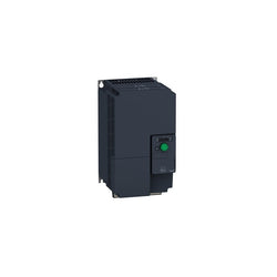
variable speed drive, ATV320, 11 kW, 380500 V, 3 phases, compact

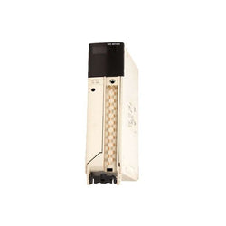
Discrete input module Modicon Quantum - 32 I - 115 V AC
This SD card is part of the Modicon M340 range, an offer of Programmable Automation Controllers (PAC). This SD flash memory card is an accessory of M340 processor. It is designed with data storage memory capacity of 8MB. This product is robust, high quality and based on the latest innovative technology. It supports transparent ready class B10 web server. It weighs 0.002kg. It is suitable for process industries, renewable energies, water, cement, manufacturing, infrastructures and machines applications. This memory card is compatible with Modicon M340 BMXP342010, BMXP342000, BMXP341000, BMXP342030, BMXP342020 process module and BMXPRA0100 peripheral remote I/O adaptor. The SD card is to be inserted in the front slot equipped with a protective door. Compact-shaped, Modicon M340 offers in small box flexibility and integrated functions. In the heart of process, it provides you plug and work solutions with both Schneider Electric and third party devices. This card is intended for backing up the two memory areas on the processor module's internal RAM. The data is backed up automatically by duplication, when the Programmable Logic Controller (PLC) is turned off.
Main
| Characteristic | Value(s) |
|---|---|
| Range of Product | Modicon M340 automation platform |
| Accessory / Separate Part Type | Memory card |
| Product Compatibility | BMXP342010 BMXP342000 BMXP341000 BMXP342030 BMXP342020 BMXPRA0100 |
| Memory capacity | 8 MB |
| Web server | Transparent ready class B10 |
Complementary
| Characteristic | Value(s) |
|---|---|
| Product Weight | 0.004 lb(US) (0.002 kg) |
Analog input module Modicon Premium - 4 I multirange

This product is part of the Modicon TM5 range, an offer of modules for IP20 modular I/O system. The bus base has rated supply voltage of 24V DC. This distributed I/O solution is simple, open and flexible, meeting needs in every stage of the product life cycle The housing colour is white. It weighs 0.02kg. The Modicon TM5 meets the typical requirements of production and packaging machinery, as well as material handling and assembly systems. This product is compatible with remote transmitter module, counter module, 24V DC slice discrete modules, common distribution module and analogue module. The range is Modicon LMC058 motion controller and Modicon M258 logic controller. This IP20 modular IO system provides a flexible and scalable configuration of expansions/distributed I/O islands by connection with Modicon controllers (TM5 bus) or via CANopen bus/Sercos bus for Modicon and PacDrive 3 controllers as well. Flexible and scalable, designed for complex machines.
Main
| Characteristic | Value(s) |
|---|---|
| Range of Product | Modicon TM5 |
| Accessory / Separate Part Type | Bus base |
| Accessory / separate part category | Communication accessories |
| Product Compatibility | Remote transmitter module Counter module 24 V DC slice discrete modules Common distribution module Analog module |
| Sale per indivisible quantity | 1 |
Complementary
| Characteristic | Value(s) |
|---|---|
| Range Compatibility | Modicon LMC058 Modicon M258 |
| Color | White |
| [Us] rated supply voltage | 24 V DC |
| Product Weight | 0.04 lb(US) (0.02 kg) |
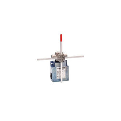
limit switch XCKMR - stay put crossed rods lever 6mm - 2x(2 NC) - slow - Pg13
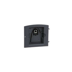
door mounting kit - for remote graphic terminal - variable speed drive - IP54
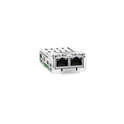
This Altivar Ethernet TCP/IP communication module has 2 ports with RJ45 connectors. It is compatible with Altivar Machine ATV320, Lexium 32 and Altivar 32. Removable module allows last minute decisions on drive communication protocol and thus facilitates installation project management.
Main
| Characteristic | Value(s) |
|---|---|
| Range of Product | Altivar |
| Product or Component Type | Communication module |
| Accessory / separate part category | Communication accessories |
Complementary
| Characteristic | Value(s) |
|---|---|
| Product Compatibility | Lexium 32M |
| Range compatibility | Altivar Machine ATV320 Altivar 32 Lexium 32 |
| Communication Port Protocol | Modbus TCP EtherNet/IP |
| Electrical connection | 1 connector RJ45, EtherNet/IP 1 connector RJ45, Modbus TCP |
| Transmission Rate | 10/100 Mbps |
| Addressing | IP addressing manual, BOOTP or DHCP |
| Exchange mode | Half duplex and full duplex |
| Communication service | Up to 8 connections (includes connections of Modbus TCP/Ethernet IP) Ethernet IP/Modbus TCP FDR Agent Ethernet IP/Modbus TCP Read holding registers (03), 63 words max Modbus TCP Read input registers (04), 63 words max Modbus TCP Write single register (06) Modbus TCP Write multiple registers (16), 63 words max Modbus TCP Read/write multiple registers (23) Modbus TCP Read device identification (43) Modbus TCP Diagnostics (08) Modbus TCP I/O scanner : read/write, 6 words maximum Modbus TCP Communication monitoring Modbus TCP SNMP agent Ethernet IP Master/Slave hierarchy ODVA AC drive profile and CiA 402 profile Ethernet IP Fixed communication monitoring adjusted by Ethernet IP scanner adaptor (Master) Ethernet IP |
| Display type | 1 LED MS (Module Status) 1 LED NS (Network Status) 1 LED Ethernet port activity 1 LED Modbus TCP port activity |
| Product Weight | 0.7 lb(US) (0.3 kg) |

Profinet communication module