
 1 year warranty


Ordering
1 piece
85364900
Popular Downloads
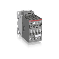
Dimensions
45 mm
139.5 mm
86 mm
0.54 kg
Technical
3
0
2
2
3P
IEC/EN 60947-1, IEC/EN 60947-4-1, UL 60335-2-40 LZGH2 A2L, UL 60947-4-1, CSA C22.2 No. 60335-2-40 LZGH2 A2L, CSA C22.2 No. 60947-4-1
Auxiliary Circuit 690 V
Main Circuit 690 V
Auxiliary Circuit 690 V
Main Circuit 690 V
Auxiliary Circuit 50 / 60 Hz
Main Circuit 50 / 60 Hz
Auxiliary Circuit 50 / 60 Hz
Main Circuit 50 / 60 Hz
acc. to IEC 60947-4-1, Open Contactors Θ = 40 °C 50 A
acc. to IEC 60947-5-1, Θ = 40 °C 16 A
acc. to IEC 60947-4-1, Open Contactors Θ = 40 °C 50 A
acc. to IEC 60947-5-1, Θ = 40 °C 16 A
(690 V) 40 °C 45 A
(690 V) 60 °C 40 A
(690 V) 70 °C 32 A
(690 V) 40 °C 45 A
(690 V) 60 °C 40 A
(690 V) 70 °C 32 A
(415 V) 60 °C 26 A
(440 V) 60 °C 26 A
(500 V) 60 °C 23 A
(690 V) 60 °C 17 A
(380 / 400 V) 60 °C 26 A
(220 / 230 / 240 V) 60 °C 26 A
(415 V) 60 °C 26 A
(440 V) 60 °C 26 A
(500 V) 60 °C 23 A
(690 V) 60 °C 17 A
(380 / 400 V) 60 °C 26 A
(220 / 230 / 240 V) 60 °C 26 A
(415 V) 60 °C 26 A
(440 V) 60 °C 26 A
(500 V) 60 °C 23 A
(690 V) 60 °C 17 A
(380 / 400 V) 60 °C 26 A
(220 / 230 / 240 V) 60 °C 26 A
(415 V) 60 °C 26 A
(440 V) 60 °C 26 A
(500 V) 60 °C 23 A
(690 V) 60 °C 17 A
(380 / 400 V) 60 °C 26 A
(220 / 230 / 240 V) 60 °C 26 A
(500 V) 2 A
(690 V) 2 A
(24 / 127 V) 6 A
(220 / 240 V) 4 A
(400 / 440 V) 3 A
(500 V) 2 A
(690 V) 2 A
(24 / 127 V) 6 A
(220 / 240 V) 4 A
(400 / 440 V) 3 A
(110 V) 2 Poles in Series, 40 °C 45 A
(110 V) 2 Poles in Series, 60 °C 40 A
(110 V) 2 Poles in Series, 70 °C 32 A
(110 V) 3 Poles in Series, 40 °C 45 A
(110 V) 3 Poles in Series, 60 °C 40 A
(110 V) 3 Poles in Series, 70 °C 32 A
(220 V) 3 Poles in Series, 40 °C 45 A
(220 V) 3 Poles in Series, 60 °C 40 A
(220 V) 3 Poles in Series, 70 °C 32 A
(72 V) 1-Pole, 40 °C 45 A
(72 V) 1-Pole, 60 °C 40 A
(72 V) 1-Pole, 70 °C 32 A
(72 V) 2 Poles in Series, 40 °C 45 A
(72 V) 2 Poles in Series, 60 °C 40 A
(72 V) 2 Poles in Series, 70 °C 32 A
(72 V) 3 Poles in Series, 40 °C 45 A
(72 V) 3 Poles in Series, 60 °C 40 A
(72 V) 3 Poles in Series, 70 °C 32 A
(110 V) 2 Poles in Series, 40 °C 45 A
(110 V) 2 Poles in Series, 60 °C 40 A
(110 V) 2 Poles in Series, 70 °C 32 A
(110 V) 3 Poles in Series, 40 °C 45 A
(110 V) 3 Poles in Series, 60 °C 40 A
(110 V) 3 Poles in Series, 70 °C 32 A
(220 V) 3 Poles in Series, 40 °C 45 A
(220 V) 3 Poles in Series, 60 °C 40 A
(220 V) 3 Poles in Series, 70 °C 32 A
(72 V) 1-Pole, 40 °C 45 A
(72 V) 1-Pole, 60 °C 40 A
(72 V) 1-Pole, 70 °C 32 A
(72 V) 2 Poles in Series, 40 °C 45 A
(72 V) 2 Poles in Series, 60 °C 40 A
(72 V) 2 Poles in Series, 70 °C 32 A
(72 V) 3 Poles in Series, 40 °C 45 A
(72 V) 3 Poles in Series, 60 °C 40 A
(72 V) 3 Poles in Series, 70 °C 32 A
(110 V) 2 Poles in Series, 40 °C 45 A
(110 V) 2 Poles in Series, 60 °C 40 A
(110 V) 2 Poles in Series, 70 °C 32 A
(110 V) 3 Poles in Series, 40 °C 45 A
(110 V) 3 Poles in Series, 60 °C 40 A
(110 V) 3 Poles in Series, 70 °C 32 A
(220 V) 3 Poles in Series, 40 °C 45 A
(220 V) 3 Poles in Series, 60 °C 40 A
(220 V) 3 Poles in Series, 70 °C 32 A
(72 V) 1-Pole, 40 °C 45 A
(110 V) 2 Poles in Series, 40 °C 45 A
(110 V) 2 Poles in Series, 60 °C 40 A
(110 V) 2 Poles in Series, 70 °C 32 A
(110 V) 3 Poles in Series, 40 °C 45 A
(110 V) 3 Poles in Series, 60 °C 40 A
(110 V) 3 Poles in Series, 70 °C 32 A
(220 V) 3 Poles in Series, 40 °C 20 A
(220 V) 3 Poles in Series, 60 °C 20 A
(220 V) 3 Poles in Series, 70 °C 20 A
(72 V) 1-Pole, 40 °C 20 A
(72 V) 1-Pole, 60 °C 20 A
(72 V) 1-Pole, 70 °C 20 A
(72 V) 2 Poles in Series, 40 °C 45 A
(72 V) 2 Poles in Series, 60 °C 40 A
(72 V) 2 Poles in Series, 70 °C 32 A
(72 V) 3 Poles in Series, 40 °C 45 A
(72 V) 3 Poles in Series, 60 °C 40 A
(72 V) 3 Poles in Series, 70 °C 32 A
(110 V) 2 Poles in Series, 40 °C 45 A
(110 V) 2 Poles in Series, 60 °C 40 A
(110 V) 2 Poles in Series, 70 °C 32 A
(110 V) 3 Poles in Series, 40 °C 45 A
(110 V) 3 Poles in Series, 60 °C 40 A
(110 V) 3 Poles in Series, 70 °C 32 A
(220 V) 3 Poles in Series, 40 °C 20 A
(220 V) 3 Poles in Series, 60 °C 20 A
(220 V) 3 Poles in Series, 70 °C 20 A
(72 V) 1-Pole, 40 °C 20 A
(24 V) 6 A / 144 W
(48 V) 2.8 A / 134 W
(72 V) 1 A / 72 W
(110 V) 0.55 A / 60 W
(125 V) 0.55 A / 69 W
(220 V) 0.27 A / 60 W
(250 V) 0.27 A / 68 W
(400 V) 0.15 A / 60 W
(500 V) 0.13 A / 65 W
(600 V) 0.1 A / 60 W
(24 V) 6 A / 144 W
(48 V) 2.8 A / 134 W
(72 V) 1 A / 72 W
(110 V) 0.55 A / 60 W
(125 V) 0.55 A / 69 W
(220 V) 0.27 A / 60 W
(250 V) 0.27 A / 68 W
(400 V) 0.15 A / 60 W
(500 V) 0.13 A / 65 W
(600 V) 0.1 A / 60 W
(400 V) 11 kW
(415 V) 11 kW
(440 V) 15 kW
(500 V) 15 kW
(690 V) 15 kW
(380 / 400 V) 11 kW
(220 / 230 / 240 V) 6.5 kW
(400 V) 11 kW
(415 V) 11 kW
(440 V) 15 kW
(500 V) 15 kW
(690 V) 15 kW
(380 / 400 V) 11 kW
(220 / 230 / 240 V) 6.5 kW
(415 V) 11 kW
(440 V) 15 kW
(500 V) 15 kW
(690 V) 15 kW
(380 / 400 V) 11 kW
(220 / 230 / 240 V) 6.5 kW
(415 V) 11 kW
(440 V) 15 kW
(500 V) 15 kW
(690 V) 15 kW
(380 / 400 V) 11 kW
(220 / 230 / 240 V) 6.5 kW
at 40 °C Ambient Temp, in Free Air, from a Cold State 10 s 350 A
at 40 °C Ambient Temp, in Free Air, from a Cold State 15 min 50 A
at 40 °C Ambient Temp, in Free Air, from a Cold State 1 min 150 A
at 40 °C Ambient Temp, in Free Air, from a Cold State 1 s 700 A
at 40 °C Ambient Temp, in Free Air, from a Cold State 30 s 225 A
for 0.1 s 140 A
for 1 s 100 A
cos phi=0.45 (cos phi=0.35 for Ie > 100 A) at 440 V 500 A
cos phi=0.45 (cos phi=0.35 for Ie > 100 A) at 690 V 200 A
cos phi=0.45 (cos phi=0.35 for Ie > 100 A) at 440 V 500 A
cos phi=0.45 (cos phi=0.35 for Ie > 100 A) at 690 V 200 A
acc. to IEC 60947-4-1 690 V
acc. to IEC 60947-5-1 690 V
acc. to UL/CSA 600 V
acc. to IEC 60947-4-1 690 V
acc. to IEC 60947-5-1 690 V
acc. to UL/CSA 600 V
6 kV
(AC-1) 600 cycles per hour
(AC-15) 1200 cycles per hour
(AC-2 / AC-4) 150 cycles per hour
(AC-3) 1200 cycles per hour
(DC-13) 900 cycles per hour
(AC-1) 600 cycles per hour
(AC-15) 1200 cycles per hour
(AC-2 / AC-4) 150 cycles per hour
(AC-3) 1200 cycles per hour
(DC-13) 900 cycles per hour
3600 cycles per hour
DC Operation 24 V
at 6 A per Pole 0.1 W
at Rated Operating Conditions AC-1 per Pole 1.8 W
at Rated Operating Conditions AC-3 per Pole 0.6 W
at 6 A per Pole 0.1 W
at Rated Operating Conditions AC-1 per Pole 1.8 W
at Rated Operating Conditions AC-3 per Pole 0.6 W
Between Coil De-energization and NC Contact Closing 22 ... 57 ms
Between Coil De-energization and NO Contact Opening 17 ... 29 ms
Between Coil Energization and NC Contact Opening 20 ... 35 ms
Between Coil Energization and NO Contact Closing 27 ... 53 ms
Between Coil De-energization and NC Contact Closing 22 ... 57 ms
Between Coil De-energization and NO Contact Opening 17 ... 29 ms
Between Coil Energization and NC Contact Opening 20 ... 35 ms
Between Coil Energization and NO Contact Closing 27 ... 53 ms
TH35-15 (35 x 15 mm Mounting Rail) acc. to IEC 60715
TH35-7.5 (35 x 7.5 mm Mounting Rail) acc. to IEC 60715
TH35-15 (35 x 15 mm Mounting Rail) acc. to IEC 60715
TH35-7.5 (35 x 7.5 mm Mounting Rail) acc. to IEC 60715
2 x M4 Screws Placed Diagonally
Flexible with Ferrule 1/2x 1.5 ... 10 mm²
Flexible with Insulated Ferrule 1x 1.5 ... 10 mm²
Flexible with Insulated Ferrule 2x 1.5 ... 4 mm²
Rigid Solid 1/2x 2.5 ... 4 mm²
Rigid Stranded 1/2x 2.5 ... 10 mm²
Flexible with Ferrule 1/2x 1.5 ... 10 mm²
Flexible with Insulated Ferrule 1x 1.5 ... 10 mm²
Flexible with Insulated Ferrule 2x 1.5 ... 4 mm²
Rigid Solid 1/2x 2.5 ... 4 mm²
Rigid Stranded 1/2x 2.5 ... 10 mm²
Flexible with Ferrule 1/2x 0.75 ... 2.5 mm²
Flexible with Insulated Ferrule 1x 0.75 ... 2.5 mm²
Flexible with Insulated Ferrule 2x 0.75 ... 1.5 mm²
Rigid Solid 1/2x 1 ... 2.5 mm²
Rigid Stranded 1/2x 1 ... 2.5 mm²
Flexible with Ferrule 1/2x 0.75 ... 2.5 mm²
Flexible with Insulated Ferrule 1x 0.75 ... 2.5 mm²
Flexible with Insulated Ferrule 2x 0.75 ... 1.5 mm²
Rigid Solid 1/2x 1 ... 2.5 mm²
Rigid Stranded 1/2x 1 ... 2.5 mm²
Flexible with Ferrule 1/2x 0.75 ... 2.5 mm²
Flexible with Insulated Ferrule 1x 0.75 ... 2.5 mm²
Flexible with Insulated Ferrule 2x 0.75 ... 1.5 mm²
Rigid Solid 1/2x 1 ... 2.5 mm²
Rigid Stranded 1/2x 1 ... 2.5 mm²
Flexible with Ferrule 1/2x 0.75 ... 2.5 mm²
Flexible with Insulated Ferrule 1x 0.75 ... 2.5 mm²
Flexible with Insulated Ferrule 2x 0.75 ... 1.5 mm²
Rigid Solid 1/2x 1 ... 2.5 mm²
Rigid Stranded 1/2x 1 ... 2.5 mm²
Auxiliary Circuit 10 mm
Control Circuit 10 mm
Main Circuit 14 mm
Auxiliary Circuit 10 mm
Control Circuit 10 mm
Main Circuit 14 mm
acc. to IEC 60529, IEC 60947-1, EN 60529 Auxiliary Terminals IP20
acc. to IEC 60529, IEC 60947-1, EN 60529 Coil Terminals IP20
acc. to IEC 60529, IEC 60947-1, EN 60529 Main Terminals IP20
acc. to IEC 60529, IEC 60947-1, EN 60529 Auxiliary Terminals IP20
acc. to IEC 60529, IEC 60947-1, EN 60529 Coil Terminals IP20
acc. to IEC 60529, IEC 60947-1, EN 60529 Main Terminals IP20
Auxiliary Circuit 1.2 N·m
Control Circuit 1.2 N·m
Main Circuit 2.5 N·m
Auxiliary Circuit 1.2 N·m
Control Circuit 1.2 N·m
Main Circuit 2.5 N·m
Screw Terminals
Block Contactor
Technical UL/CSA
Main Circuit 600 V
(600 V AC) 45 A
(120 V AC) Single Phase 2 hp
(200 ... 208 V AC) Three Phase 7-1/2 hp
(220 ... 240 V AC) Three Phase 7-1/2 hp
(240 V AC) Single Phase 3 hp
(440 ... 480 V AC) Three Phase 15 hp
(550 ... 600 V AC) Three Phase 20 hp
(120 V AC) Single Phase 2 hp
(200 ... 208 V AC) Three Phase 7-1/2 hp
(220 ... 240 V AC) Three Phase 7-1/2 hp
(240 V AC) Single Phase 3 hp
(440 ... 480 V AC) Three Phase 15 hp
(550 ... 600 V AC) Three Phase 20 hp
Rigid Solid 1/2x 14-10 AWG
Rigid Stranded 1/2x 14-8 AWG
Rigid Solid 1/2x 14-10 AWG
Rigid Stranded 1/2x 14-8 AWG
Rigid Solid 1/2x 18-14 AWG
Rigid Stranded 1/2x 18-14 AWG
Rigid Solid 1/2x 18-14 AWG
Rigid Stranded 1/2x 18-14 AWG
Rigid Solid 1/2x 18-14 AWG
Rigid Stranded 1/2x 18-14 AWG
Rigid Solid 1/2x 18-14 AWG
Rigid Stranded 1/2x 18-14 AWG
Auxiliary Circuit 11 in·lb
Control Circuit 11 in·lb
Main Circuit 22 in·lb
Auxiliary Circuit 11 in·lb
Control Circuit 11 in·lb
Main Circuit 22 in·lb
(120 V AC) Single Phase 24 A
(200 ... 208 V AC) Three Phase 25.3 A
(220 ... 240 V AC) Three Phase 22 A
(240 V AC) Single Phase 17 A
(440 ... 480 V AC) Three Phase 21 A
(550 ... 600 V AC) Three Phase 22 A
(120 V AC) Single Phase 24 A
(200 ... 208 V AC) Three Phase 25.3 A
(220 ... 240 V AC) Three Phase 22 A
(240 V AC) Single Phase 17 A
(440 ... 480 V AC) Three Phase 21 A
(550 ... 600 V AC) Three Phase 22 A
Environmental
Close to Contactor Fitted with Thermal O/L Relay -25 ... 60 °C
Close to Contactor without Thermal O/L Relay -40 ... 70 °C
Close to Contactor for Storage -60 ... +80 °C
Close to Contactor Fitted with Thermal O/L Relay -25 ... 60 °C
Close to Contactor without Thermal O/L Relay -40 ... 70 °C
Close to Contactor for Storage -60 ... +80 °C
Category B according to IEC 60947-1 Annex Q
Without Derating 3000 m
Closed, Shock Direction: A 30 g
Closed, Shock Direction: B1 25 g
Closed, Shock Direction: B2 15 g
Closed, Shock Direction: C1 25 g
Closed, Shock Direction: C2 25 g
Closed, Shock Direction: A 30 g
Closed, Shock Direction: B1 25 g
Closed, Shock Direction: B2 15 g
Closed, Shock Direction: C1 25 g
Closed, Shock Direction: C2 25 g
4g Closed Position & 2g Open position 5 ... 300 Hz
3
Material Compliance
Business To Business
5. Small Equipment (No External Dimension More Than 50 cm)
ABB EcoSolutions
Recycled Cardboard - 86 %
Recycled Metal - 28 %
Certificates and Declarations
Container Information
box 1 piece
96 mm
145 mm
50 mm
0.591 kg
3471523158498
crate 12 piece
51 mm
98 mm
148 mm
7.092 kg
External Classifications and Standards
Q
EC000066 - Power contactor, AC switching
EC000066 - Power contactor, AC switching
EC000066 - Power contactor, AC switching
V11.0 : 27371003
39121529
4758 >> Iec Contactors
3708048
3210680
Ordering
1 piece
85364900
Popular Downloads
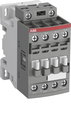
Dimensions
45 mm
101 mm
86 mm
0.4 kg
Technical
4
0
0
0
4P
IEC/EN 60947-1, IEC/EN 60947-4-1, UL 60335-2-40 LZGH2 A2L, UL 60947-1, UL 60947-4-1, CSA C22.2 No. 60335-2-40 LZGH2 A2L, CAN/CSA C22.2 No.60947-1, CAN/CSA C22.2 No.60947-4-1
Main Circuit 690 V
Main Circuit 50 / 60 Hz
acc. to IEC 60947-4-1, Open Contactors Θ = 40 °C 55 A
(690 V) 40 °C 45 A
(690 V) 60 °C 40 A
(690 V) 70 °C 32 A
(690 V) 40 °C 45 A
(690 V) 60 °C 40 A
(690 V) 70 °C 32 A
(415 V) 60 °C 21.2 A
(440 V) 60 °C 20 A
(500 V) 60 °C 17.6 A
(690 V) 60 °C 10.5 A
(380 / 400 V) 60 °C 22 A
(220 / 230 / 240 V) 60 °C 23.2 A
(415 V) 60 °C 21.2 A
(440 V) 60 °C 20 A
(500 V) 60 °C 17.6 A
(690 V) 60 °C 10.5 A
(380 / 400 V) 60 °C 22 A
(220 / 230 / 240 V) 60 °C 23.2 A
(110 V) 2 Poles in Series, 40 °C 45 A
(110 V) 2 Poles in Series, 60 °C 40 A
(110 V) 2 Poles in Series, 70 °C 32 A
(110 V) 3 Poles in Series, 40 °C 45 A
(110 V) 3 Poles in Series, 60 °C 40 A
(110 V) 3 Poles in Series, 70 °C 32 A
(110 V) 4 Poles in Series, 40 °C 45 A
(110 V) 4 Poles in Series, 60 °C 40 A
(110 V) 4 Poles in Series, 70 °C 32 A
(220 V) 3 Poles in Series, 40 °C 45 A
(220 V) 3 Poles in Series, 60 °C 40 A
(220 V) 3 Poles in Series, 70 °C 32 A
(220 V) 4 Poles in Series, 40 °C 45 A
(220 V) 4 Poles in Series, 60 °C 40 A
(220 V) 4 Poles in Series, 70 °C 32 A
(72 V) 1-Pole, 40 °C 45 A
(72 V) 1-Pole, 60 °C 40 A
(72 V) 1-Pole, 70 °C 32 A
(72 V) 2 Poles in Series, 40 °C 45 A
(72 V) 2 Poles in Series, 60 °C 40 A
(72 V) 2 Poles in Series, 70 °C 32 A
(72 V) 3 Poles in Series, 40 °C 45 A
(72 V) 3 Poles in Series, 60 °C 40 A
(72 V) 3 Poles in Series, 70 °C 32 A
(72 V) 4 Poles in Series, 40 °C 45 A
(72 V) 4 Poles in Series, 60 °C 40 A
(72 V) 4 Poles in Series, 70 °C 32 A
(110 V) 2 Poles in Series, 40 °C 45 A
(110 V) 2 Poles in Series, 60 °C 40 A
(110 V) 2 Poles in Series, 70 °C 32 A
(110 V) 3 Poles in Series, 40 °C 45 A
(110 V) 3 Poles in Series, 60 °C 40 A
(110 V) 3 Poles in Series, 70 °C 32 A
(110 V) 4 Poles in Series, 40 °C 45 A
(110 V) 4 Poles in Series, 60 °C 40 A
(110 V) 4 Poles in Series, 70 °C 32 A
(220 V) 3 Poles in Series, 40 °C 45 A
(400 V) 11 kW
(415 V) 11 kW
(440 V) 11 kW
(500 V) 11 kW
(690 V) 9 kW
(220 / 230 / 240 V) 5.5 kW
(400 V) 11 kW
(415 V) 11 kW
(440 V) 11 kW
(500 V) 11 kW
(690 V) 9 kW
(220 / 230 / 240 V) 5.5 kW
at 40 °C Ambient Temp, in Free Air, from a Cold State 10 s 300 A
at 40 °C Ambient Temp, in Free Air, from a Cold State 15 min 55 A
at 40 °C Ambient Temp, in Free Air, from a Cold State 1 min 150 A
at 40 °C Ambient Temp, in Free Air, from a Cold State 1 s 450 A
at 40 °C Ambient Temp, in Free Air, from a Cold State 30 s 225 A
acc. to IEC 60947-4-1 690 V
acc. to UL/CSA 600 V
acc. to IEC 60947-4-1 690 V
acc. to UL/CSA 600 V
6 kV
(AC-1) 600 cycles per hour
3600 cycles per hour
DC Operation 12 ... 20 V
at Rated Operating Conditions AC-1 per Pole 1.6 W
at Rated Operating Conditions AC-3 per Pole 0.42 W
at Rated Operating Conditions AC-1 per Pole 1.6 W
at Rated Operating Conditions AC-3 per Pole 0.42 W
Between Coil De-energization and NC Contact Closing 13 ... 98 ms
Between Coil De-energization and NO Contact Opening 11 ... 95 ms
Between Coil Energization and NC Contact Opening 38 ... 90 ms
Between Coil Energization and NO Contact Closing 40 ... 95 ms
Between Coil De-energization and NC Contact Closing 13 ... 98 ms
Between Coil De-energization and NO Contact Opening 11 ... 95 ms
Between Coil Energization and NC Contact Opening 38 ... 90 ms
Between Coil Energization and NO Contact Closing 40 ... 95 ms
TH35-15 (35 x 15 mm Mounting Rail) acc. to IEC 60715
TH35-7.5 (35 x 7.5 mm Mounting Rail) acc. to IEC 60715
TH35-15 (35 x 15 mm Mounting Rail) acc. to IEC 60715
TH35-7.5 (35 x 7.5 mm Mounting Rail) acc. to IEC 60715
2 x M4 Screws Placed Diagonally
Flexible with Ferrule 1/2x 1.5 ... 16 mm²
Flexible with Insulated Ferrule 1/2x 1.5 ... 16 mm²
Rigid Solid 1/2x 1.5 ... 4 mm²
Rigid Stranded 1/2x 1.5 ... 16 mm²
Flexible with Ferrule 1/2x 1.5 ... 16 mm²
Flexible with Insulated Ferrule 1/2x 1.5 ... 16 mm²
Rigid Solid 1/2x 1.5 ... 4 mm²
Rigid Stranded 1/2x 1.5 ... 16 mm²
Flexible with Ferrule 1/2x 0.75 ... 2.5 mm²
Flexible with Insulated Ferrule 1x 0.75 ... 2.5 mm²
Flexible with Insulated Ferrule 2x 0.75 ... 1.5 mm²
Rigid Solid 1/2x 1 ... 2.5 mm²
Rigid Stranded 1/2x 1 ... 2.5 mm²
Flexible with Ferrule 1/2x 0.75 ... 2.5 mm²
Flexible with Insulated Ferrule 1x 0.75 ... 2.5 mm²
Flexible with Insulated Ferrule 2x 0.75 ... 1.5 mm²
Rigid Solid 1/2x 1 ... 2.5 mm²
Rigid Stranded 1/2x 1 ... 2.5 mm²
Control Circuit 10 mm
Main Circuit 12 mm
Control Circuit 10 mm
Main Circuit 12 mm
acc. to IEC 60529, IEC 60947-1, EN 60529 Coil Terminals IP20
acc. to IEC 60529, IEC 60947-1, EN 60529 Main Terminals IP20
acc. to IEC 60529, IEC 60947-1, EN 60529 Coil Terminals IP20
acc. to IEC 60529, IEC 60947-1, EN 60529 Main Terminals IP20
Control Circuit 1.2 N·m
Main Circuit 2.5 N·m
Control Circuit 1.2 N·m
Main Circuit 2.5 N·m
Screw Terminals
Block Contactor
Technical UL/CSA
Main Circuit 600 V
(600 V AC) 45 A
Rigid Solid 1/2x 16-10 AWG
Rigid Stranded 1/2x 16-6 AWG
Rigid Solid 1/2x 16-10 AWG
Rigid Stranded 1/2x 16-6 AWG
Rigid Solid 1/2x 18-14 AWG
Rigid Stranded 1/2x 18-14 AWG
Rigid Solid 1/2x 18-14 AWG
Rigid Stranded 1/2x 18-14 AWG
Control Circuit 11 in·lb
Main Circuit 22 in·lb
Control Circuit 11 in·lb
Main Circuit 22 in·lb
Environmental
Close to Contactor for Storage -60 ... +80 °C
Near Contactor for Operation in Free Air -40 ... 70 °C
Close to Contactor for Storage -60 ... +80 °C
Near Contactor for Operation in Free Air -40 ... 70 °C
Category B according to IEC 60947-1 Annex Q
Without Derating 3000 m
Closed, Shock Direction: B1 25 g
Open, Shock Direction: B1 5 g
Shock Direction: A 30 g
Shock Direction: B2 15 g
Shock Direction: C1 25 g
Shock Direction: C2 25 g
Closed, Shock Direction: B1 25 g
Open, Shock Direction: B1 5 g
Shock Direction: A 30 g
Shock Direction: B2 15 g
Shock Direction: C1 25 g
Shock Direction: C2 25 g
4g Closed Position & 2g Open position 5 ... 300 Hz
3
Material Compliance
Following EU Directive 2011/65/EU and Amendment 2015/863 July 22, 2019
Business To Business
5. Small Equipment (No External Dimension More Than 50 cm)
ABB EcoSolutions
Recycled Cardboard - 86 %
Recycled Metal - 28 %
Certificates and Declarations
Container Information
box 1 piece
87 mm
103 mm
47 mm
0.4 kg
3471523116009
box 18 piece
250 mm
300 mm
315 mm
14.4 kg
External Classifications and Standards
Q
EC000066 - Power contactor, AC switching
EC000066 - Power contactor, AC switching
EC000066 - Power contactor, AC switching
V11.0 : 27371003
39121529
4758 >> Iec Contactors
3705832

Ordering
1 piece
85364900
Popular Downloads
Dimensions
45 mm
101 mm
86 mm
0.4 kg
Technical
4
0
0
0
4P
IEC/EN 60947-1, IEC/EN 60947-4-1, UL 60335-2-40 LZGH2 A2L, UL 60947-1, UL 60947-4-1, CSA C22.2 No. 60335-2-40 LZGH2 A2L, CAN/CSA C22.2 No.60947-1, CAN/CSA C22.2 No.60947-4-1
Main Circuit 690 V
Control Circuit 50 / 60 Hz
Main Circuit 50 / 60 Hz
Control Circuit 50 / 60 Hz
Main Circuit 50 / 60 Hz
acc. to IEC 60947-4-1, Open Contactors Θ = 40 °C 55 A
(690 V) 40 °C 45 A
(690 V) 60 °C 40 A
(690 V) 70 °C 32 A
(690 V) 40 °C 45 A
(690 V) 60 °C 40 A
(690 V) 70 °C 32 A
(415 V) 60 °C 21.2 A
(440 V) 60 °C 20 A
(500 V) 60 °C 17.6 A
(690 V) 60 °C 10.5 A
(380 / 400 V) 60 °C 22 A
(220 / 230 / 240 V) 60 °C 23.2 A
(415 V) 60 °C 21.2 A
(440 V) 60 °C 20 A
(500 V) 60 °C 17.6 A
(690 V) 60 °C 10.5 A
(380 / 400 V) 60 °C 22 A
(220 / 230 / 240 V) 60 °C 23.2 A
(110 V) 2 Poles in Series, 40 °C 45 A
(110 V) 2 Poles in Series, 60 °C 40 A
(110 V) 2 Poles in Series, 70 °C 32 A
(110 V) 3 Poles in Series, 40 °C 45 A
(110 V) 3 Poles in Series, 60 °C 40 A
(110 V) 3 Poles in Series, 70 °C 32 A
(110 V) 4 Poles in Series, 40 °C 45 A
(110 V) 4 Poles in Series, 60 °C 40 A
(110 V) 4 Poles in Series, 70 °C 32 A
(220 V) 3 Poles in Series, 40 °C 45 A
(220 V) 3 Poles in Series, 60 °C 40 A
(220 V) 3 Poles in Series, 70 °C 32 A
(220 V) 4 Poles in Series, 40 °C 45 A
(220 V) 4 Poles in Series, 60 °C 40 A
(220 V) 4 Poles in Series, 70 °C 32 A
(72 V) 1-Pole, 40 °C 45 A
(72 V) 1-Pole, 60 °C 40 A
(72 V) 1-Pole, 70 °C 32 A
(72 V) 2 Poles in Series, 40 °C 45 A
(72 V) 2 Poles in Series, 60 °C 40 A
(72 V) 2 Poles in Series, 70 °C 32 A
(72 V) 3 Poles in Series, 40 °C 45 A
(72 V) 3 Poles in Series, 60 °C 40 A
(72 V) 3 Poles in Series, 70 °C 32 A
(72 V) 4 Poles in Series, 40 °C 45 A
(72 V) 4 Poles in Series, 60 °C 40 A
(72 V) 4 Poles in Series, 70 °C 32 A
(110 V) 2 Poles in Series, 40 °C 45 A
(110 V) 2 Poles in Series, 60 °C 40 A
(110 V) 2 Poles in Series, 70 °C 32 A
(110 V) 3 Poles in Series, 40 °C 45 A
(110 V) 3 Poles in Series, 60 °C 40 A
(110 V) 3 Poles in Series, 70 °C 32 A
(110 V) 4 Poles in Series, 40 °C 45 A
(110 V) 4 Poles in Series, 60 °C 40 A
(110 V) 4 Poles in Series, 70 °C 32 A
(220 V) 3 Poles in Series, 40 °C 45 A
(400 V) 11 kW
(415 V) 11 kW
(440 V) 11 kW
(500 V) 11 kW
(690 V) 9 kW
(220 / 230 / 240 V) 5.5 kW
(400 V) 11 kW
(415 V) 11 kW
(440 V) 11 kW
(500 V) 11 kW
(690 V) 9 kW
(220 / 230 / 240 V) 5.5 kW
at 40 °C Ambient Temp, in Free Air, from a Cold State 10 s 300 A
at 40 °C Ambient Temp, in Free Air, from a Cold State 15 min 55 A
at 40 °C Ambient Temp, in Free Air, from a Cold State 1 min 150 A
at 40 °C Ambient Temp, in Free Air, from a Cold State 1 s 450 A
at 40 °C Ambient Temp, in Free Air, from a Cold State 30 s 225 A
at 40 °C Ambient Temp, in Free Air, from a Cold State 10 s 300 A
at 40 °C Ambient Temp, in Free Air, from a Cold State 15 min 55 A
at 40 °C Ambient Temp, in Free Air, from a Cold State 1 min 150 A
at 40 °C Ambient Temp, in Free Air, from a Cold State 1 s 450 A
at 40 °C Ambient Temp, in Free Air, from a Cold State 30 s 225 A
acc. to IEC 60947-4-1 690 V
acc. to UL/CSA 600 V
acc. to IEC 60947-4-1 690 V
acc. to UL/CSA 600 V
6 kV
(AC-1) 600 cycles per hour
3600 cycles per hour
50 Hz 24 ... 60 V
60 Hz 24 ... 60 V
DC Operation 20 ... 60 V
50 Hz 24 ... 60 V
60 Hz 24 ... 60 V
DC Operation 20 ... 60 V
at Rated Operating Conditions AC-1 per Pole 1.6 W
at Rated Operating Conditions AC-3 per Pole 0.42 W
at Rated Operating Conditions AC-1 per Pole 1.6 W
at Rated Operating Conditions AC-3 per Pole 0.42 W
Between Coil De-energization and NC Contact Closing 13 ... 98 ms
Between Coil De-energization and NO Contact Opening 11 ... 95 ms
Between Coil Energization and NC Contact Opening 38 ... 90 ms
Between Coil Energization and NO Contact Closing 40 ... 95 ms
Between Coil De-energization and NC Contact Closing 13 ... 98 ms
Between Coil De-energization and NO Contact Opening 11 ... 95 ms
Between Coil Energization and NC Contact Opening 38 ... 90 ms
Between Coil Energization and NO Contact Closing 40 ... 95 ms
TH35-15 (35 x 15 mm Mounting Rail) acc. to IEC 60715
TH35-7.5 (35 x 7.5 mm Mounting Rail) acc. to IEC 60715
TH35-15 (35 x 15 mm Mounting Rail) acc. to IEC 60715
TH35-7.5 (35 x 7.5 mm Mounting Rail) acc. to IEC 60715
2 x M4 Screws Placed Diagonally
Flexible with Ferrule 1/2x 1.5 ... 16 mm²
Flexible with Insulated Ferrule 1/2x 1.5 ... 16 mm²
Rigid Solid 1/2x 1.5 ... 4 mm²
Rigid Stranded 1/2x 1.5 ... 16 mm²
Flexible with Ferrule 1/2x 1.5 ... 16 mm²
Flexible with Insulated Ferrule 1/2x 1.5 ... 16 mm²
Rigid Solid 1/2x 1.5 ... 4 mm²
Rigid Stranded 1/2x 1.5 ... 16 mm²
Flexible with Ferrule 1/2x 0.75 ... 2.5 mm²
Flexible with Insulated Ferrule 1x 0.75 ... 2.5 mm²
Flexible with Insulated Ferrule 2x 0.75 ... 1.5 mm²
Rigid Solid 1/2x 1 ... 2.5 mm²
Rigid Stranded 1/2x 1 ... 2.5 mm²
Flexible with Ferrule 1/2x 0.75 ... 2.5 mm²
Flexible with Insulated Ferrule 1x 0.75 ... 2.5 mm²
Flexible with Insulated Ferrule 2x 0.75 ... 1.5 mm²
Rigid Solid 1/2x 1 ... 2.5 mm²
Rigid Stranded 1/2x 1 ... 2.5 mm²
Control Circuit 10 mm
Main Circuit 12 mm
Control Circuit 10 mm
Main Circuit 12 mm
acc. to IEC 60529, IEC 60947-1, EN 60529 Coil Terminals IP20
acc. to IEC 60529, IEC 60947-1, EN 60529 Main Terminals IP20
acc. to IEC 60529, IEC 60947-1, EN 60529 Coil Terminals IP20
acc. to IEC 60529, IEC 60947-1, EN 60529 Main Terminals IP20
Control Circuit 1.2 N·m
Main Circuit 2.5 N·m
Control Circuit 1.2 N·m
Main Circuit 2.5 N·m
Screw Terminals
Block Contactor
Technical UL/CSA
Main Circuit 600 V
(600 V AC) 45 A
Rigid Solid 1/2x 16-10 AWG
Rigid Stranded 1/2x 16-6 AWG
Rigid Solid 1/2x 16-10 AWG
Rigid Stranded 1/2x 16-6 AWG
Rigid Solid 1/2x 18-14 AWG
Rigid Stranded 1/2x 18-14 AWG
Rigid Solid 1/2x 18-14 AWG
Rigid Stranded 1/2x 18-14 AWG
Control Circuit 11 in·lb
Main Circuit 22 in·lb
Control Circuit 11 in·lb
Main Circuit 22 in·lb
Environmental
Close to Contactor for Storage -60 ... +80 °C
Near Contactor for Operation in Free Air -40 ... 70 °C
Close to Contactor for Storage -60 ... +80 °C
Near Contactor for Operation in Free Air -40 ... 70 °C
Category B according to IEC 60947-1 Annex Q
Without Derating 3000 m
Closed, Shock Direction: B1 25 g
Open, Shock Direction: B1 5 g
Shock Direction: A 30 g
Shock Direction: B2 15 g
Shock Direction: C1 25 g
Shock Direction: C2 25 g
Closed, Shock Direction: B1 25 g
Open, Shock Direction: B1 5 g
Shock Direction: A 30 g
Shock Direction: B2 15 g
Shock Direction: C1 25 g
Shock Direction: C2 25 g
4g Closed Position & 2g Open position 5 ... 300 Hz
3
Material Compliance
Following EU Directive 2011/65/EU and Amendment 2015/863 July 22, 2019
Business To Business
5. Small Equipment (No External Dimension More Than 50 cm)
ABB EcoSolutions
Recycled Cardboard - 86 %
Recycled Metal - 28 %
Certificates and Declarations
Container Information
box 1 piece
87 mm
103 mm
47 mm
0.4 kg
3471523116016
box 18 piece
250 mm
300 mm
315 mm
14.4 kg
External Classifications and Standards
Q
EC000066 - Power contactor, AC switching
EC000066 - Power contactor, AC switching
EC000066 - Power contactor, AC switching
V11.0 : 27371003
39121529
4758 >> Iec Contactors
3705833
3211526

Ordering
1 piece
85364900
Popular Downloads
Dimensions
45 mm
101 mm
86 mm
0.4 kg
Technical
4
0
0
0
4P
IEC/EN 60947-1, IEC/EN 60947-4-1, UL 60335-2-40 LZGH2 A2L, UL 60947-1, UL 60947-4-1, CSA C22.2 No. 60335-2-40 LZGH2 A2L, CAN/CSA C22.2 No.60947-1, CAN/CSA C22.2 No.60947-4-1
Main Circuit 690 V
Control Circuit 50 / 60 Hz
Main Circuit 50 / 60 Hz
Control Circuit 50 / 60 Hz
Main Circuit 50 / 60 Hz
acc. to IEC 60947-4-1, Open Contactors Θ = 40 °C 55 A
(690 V) 40 °C 45 A
(690 V) 60 °C 40 A
(690 V) 70 °C 32 A
(690 V) 40 °C 45 A
(690 V) 60 °C 40 A
(690 V) 70 °C 32 A
(415 V) 60 °C 21.2 A
(440 V) 60 °C 20 A
(500 V) 60 °C 17.6 A
(690 V) 60 °C 10.5 A
(380 / 400 V) 60 °C 22 A
(220 / 230 / 240 V) 60 °C 23.2 A
(415 V) 60 °C 21.2 A
(440 V) 60 °C 20 A
(500 V) 60 °C 17.6 A
(690 V) 60 °C 10.5 A
(380 / 400 V) 60 °C 22 A
(220 / 230 / 240 V) 60 °C 23.2 A
(110 V) 2 Poles in Series, 40 °C 45 A
(110 V) 2 Poles in Series, 60 °C 40 A
(110 V) 2 Poles in Series, 70 °C 32 A
(110 V) 3 Poles in Series, 40 °C 45 A
(110 V) 3 Poles in Series, 60 °C 40 A
(110 V) 3 Poles in Series, 70 °C 32 A
(110 V) 4 Poles in Series, 40 °C 45 A
(110 V) 4 Poles in Series, 60 °C 40 A
(110 V) 4 Poles in Series, 70 °C 32 A
(220 V) 3 Poles in Series, 40 °C 45 A
(220 V) 3 Poles in Series, 60 °C 40 A
(220 V) 3 Poles in Series, 70 °C 32 A
(220 V) 4 Poles in Series, 40 °C 45 A
(220 V) 4 Poles in Series, 60 °C 40 A
(220 V) 4 Poles in Series, 70 °C 32 A
(72 V) 1-Pole, 40 °C 45 A
(72 V) 1-Pole, 60 °C 40 A
(72 V) 1-Pole, 70 °C 32 A
(72 V) 2 Poles in Series, 40 °C 45 A
(72 V) 2 Poles in Series, 60 °C 40 A
(72 V) 2 Poles in Series, 70 °C 32 A
(72 V) 3 Poles in Series, 40 °C 45 A
(72 V) 3 Poles in Series, 60 °C 40 A
(72 V) 3 Poles in Series, 70 °C 32 A
(72 V) 4 Poles in Series, 40 °C 45 A
(72 V) 4 Poles in Series, 60 °C 40 A
(72 V) 4 Poles in Series, 70 °C 32 A
(110 V) 2 Poles in Series, 40 °C 45 A
(110 V) 2 Poles in Series, 60 °C 40 A
(110 V) 2 Poles in Series, 70 °C 32 A
(110 V) 3 Poles in Series, 40 °C 45 A
(110 V) 3 Poles in Series, 60 °C 40 A
(110 V) 3 Poles in Series, 70 °C 32 A
(110 V) 4 Poles in Series, 40 °C 45 A
(110 V) 4 Poles in Series, 60 °C 40 A
(110 V) 4 Poles in Series, 70 °C 32 A
(220 V) 3 Poles in Series, 40 °C 45 A
(400 V) 11 kW
(415 V) 11 kW
(440 V) 11 kW
(500 V) 11 kW
(690 V) 9 kW
(220 / 230 / 240 V) 5.5 kW
(400 V) 11 kW
(415 V) 11 kW
(440 V) 11 kW
(500 V) 11 kW
(690 V) 9 kW
(220 / 230 / 240 V) 5.5 kW
at 40 °C Ambient Temp, in Free Air, from a Cold State 10 s 300 A
at 40 °C Ambient Temp, in Free Air, from a Cold State 15 min 55 A
at 40 °C Ambient Temp, in Free Air, from a Cold State 1 min 150 A
at 40 °C Ambient Temp, in Free Air, from a Cold State 1 s 450 A
at 40 °C Ambient Temp, in Free Air, from a Cold State 30 s 225 A
at 40 °C Ambient Temp, in Free Air, from a Cold State 10 s 300 A
at 40 °C Ambient Temp, in Free Air, from a Cold State 15 min 55 A
at 40 °C Ambient Temp, in Free Air, from a Cold State 1 min 150 A
at 40 °C Ambient Temp, in Free Air, from a Cold State 1 s 450 A
at 40 °C Ambient Temp, in Free Air, from a Cold State 30 s 225 A
acc. to IEC 60947-4-1 690 V
acc. to UL/CSA 600 V
acc. to IEC 60947-4-1 690 V
acc. to UL/CSA 600 V
6 kV
(AC-1) 600 cycles per hour
3600 cycles per hour
50 Hz 48 ... 130 V
60 Hz 48 ... 130 V
DC Operation 48 ... 130 V
50 Hz 48 ... 130 V
60 Hz 48 ... 130 V
DC Operation 48 ... 130 V
at Rated Operating Conditions AC-1 per Pole 1.6 W
at Rated Operating Conditions AC-3 per Pole 0.42 W
at Rated Operating Conditions AC-1 per Pole 1.6 W
at Rated Operating Conditions AC-3 per Pole 0.42 W
Between Coil De-energization and NC Contact Closing 13 ... 98 ms
Between Coil De-energization and NO Contact Opening 11 ... 95 ms
Between Coil Energization and NC Contact Opening 38 ... 90 ms
Between Coil Energization and NO Contact Closing 40 ... 95 ms
Between Coil De-energization and NC Contact Closing 13 ... 98 ms
Between Coil De-energization and NO Contact Opening 11 ... 95 ms
Between Coil Energization and NC Contact Opening 38 ... 90 ms
Between Coil Energization and NO Contact Closing 40 ... 95 ms
TH35-15 (35 x 15 mm Mounting Rail) acc. to IEC 60715
TH35-7.5 (35 x 7.5 mm Mounting Rail) acc. to IEC 60715
TH35-15 (35 x 15 mm Mounting Rail) acc. to IEC 60715
TH35-7.5 (35 x 7.5 mm Mounting Rail) acc. to IEC 60715
2 x M4 Screws Placed Diagonally
Flexible with Ferrule 1/2x 1.5 ... 16 mm²
Flexible with Insulated Ferrule 1/2x 1.5 ... 16 mm²
Rigid Solid 1/2x 1.5 ... 4 mm²
Rigid Stranded 1/2x 1.5 ... 16 mm²
Flexible with Ferrule 1/2x 1.5 ... 16 mm²
Flexible with Insulated Ferrule 1/2x 1.5 ... 16 mm²
Rigid Solid 1/2x 1.5 ... 4 mm²
Rigid Stranded 1/2x 1.5 ... 16 mm²
Flexible with Ferrule 1/2x 0.75 ... 2.5 mm²
Flexible with Insulated Ferrule 1x 0.75 ... 2.5 mm²
Flexible with Insulated Ferrule 2x 0.75 ... 1.5 mm²
Rigid Solid 1/2x 1 ... 2.5 mm²
Rigid Stranded 1/2x 1 ... 2.5 mm²
Flexible with Ferrule 1/2x 0.75 ... 2.5 mm²
Flexible with Insulated Ferrule 1x 0.75 ... 2.5 mm²
Flexible with Insulated Ferrule 2x 0.75 ... 1.5 mm²
Rigid Solid 1/2x 1 ... 2.5 mm²
Rigid Stranded 1/2x 1 ... 2.5 mm²
Control Circuit 10 mm
Main Circuit 12 mm
Control Circuit 10 mm
Main Circuit 12 mm
acc. to IEC 60529, IEC 60947-1, EN 60529 Coil Terminals IP20
acc. to IEC 60529, IEC 60947-1, EN 60529 Main Terminals IP20
acc. to IEC 60529, IEC 60947-1, EN 60529 Coil Terminals IP20
acc. to IEC 60529, IEC 60947-1, EN 60529 Main Terminals IP20
Control Circuit 1.2 N·m
Main Circuit 2.5 N·m
Control Circuit 1.2 N·m
Main Circuit 2.5 N·m
Screw Terminals
Block Contactor
Technical UL/CSA
Main Circuit 600 V
(600 V AC) 45 A
Rigid Solid 1/2x 16-10 AWG
Rigid Stranded 1/2x 16-6 AWG
Rigid Solid 1/2x 16-10 AWG
Rigid Stranded 1/2x 16-6 AWG
Rigid Solid 1/2x 18-14 AWG
Rigid Stranded 1/2x 18-14 AWG
Rigid Solid 1/2x 18-14 AWG
Rigid Stranded 1/2x 18-14 AWG
Control Circuit 11 in·lb
Main Circuit 22 in·lb
Control Circuit 11 in·lb
Main Circuit 22 in·lb
Environmental
Close to Contactor for Storage -60 ... +80 °C
Near Contactor for Operation in Free Air -40 ... 70 °C
Close to Contactor for Storage -60 ... +80 °C
Near Contactor for Operation in Free Air -40 ... 70 °C
Category B according to IEC 60947-1 Annex Q
Without Derating 3000 m
Closed, Shock Direction: B1 25 g
Open, Shock Direction: B1 5 g
Shock Direction: A 30 g
Shock Direction: B2 15 g
Shock Direction: C1 25 g
Shock Direction: C2 25 g
Closed, Shock Direction: B1 25 g
Open, Shock Direction: B1 5 g
Shock Direction: A 30 g
Shock Direction: B2 15 g
Shock Direction: C1 25 g
Shock Direction: C2 25 g
4g Closed Position & 2g Open position 5 ... 300 Hz
3
Material Compliance
Following EU Directive 2011/65/EU and Amendment 2015/863 July 22, 2019
Business To Business
5. Small Equipment (No External Dimension More Than 50 cm)
ABB EcoSolutions
Recycled Cardboard - 86 %
Recycled Metal - 28 %
Certificates and Declarations
Container Information
box 1 piece
87 mm
103 mm
47 mm
0.4 kg
3471523116023
box 18 piece
250 mm
300 mm
315 mm
14.4 kg
External Classifications and Standards
Q
EC000066 - Power contactor, AC switching
EC000066 - Power contactor, AC switching
EC000066 - Power contactor, AC switching
V11.0 : 27371003
39121529
4758 >> Iec Contactors
3705834

Ordering
1 piece
85364900
Popular Downloads
Dimensions
45 mm
101 mm
86 mm
0.4 kg
Technical
4
0
0
0
4P
IEC/EN 60947-1, IEC/EN 60947-4-1, UL 60335-2-40 LZGH2 A2L, UL 60947-1, UL 60947-4-1, CSA C22.2 No. 60335-2-40 LZGH2 A2L, CAN/CSA C22.2 No.60947-1, CAN/CSA C22.2 No.60947-4-1
Main Circuit 690 V
Control Circuit 50 / 60 Hz
Main Circuit 50 / 60 Hz
Control Circuit 50 / 60 Hz
Main Circuit 50 / 60 Hz
acc. to IEC 60947-4-1, Open Contactors Θ = 40 °C 55 A
(690 V) 40 °C 45 A
(690 V) 60 °C 40 A
(690 V) 70 °C 32 A
(690 V) 40 °C 45 A
(690 V) 60 °C 40 A
(690 V) 70 °C 32 A
(415 V) 60 °C 21.2 A
(440 V) 60 °C 20 A
(500 V) 60 °C 17.6 A
(690 V) 60 °C 10.5 A
(380 / 400 V) 60 °C 22 A
(220 / 230 / 240 V) 60 °C 23.2 A
(415 V) 60 °C 21.2 A
(440 V) 60 °C 20 A
(500 V) 60 °C 17.6 A
(690 V) 60 °C 10.5 A
(380 / 400 V) 60 °C 22 A
(220 / 230 / 240 V) 60 °C 23.2 A
(110 V) 2 Poles in Series, 40 °C 45 A
(110 V) 2 Poles in Series, 60 °C 40 A
(110 V) 2 Poles in Series, 70 °C 32 A
(110 V) 3 Poles in Series, 40 °C 45 A
(110 V) 3 Poles in Series, 60 °C 40 A
(110 V) 3 Poles in Series, 70 °C 32 A
(110 V) 4 Poles in Series, 40 °C 45 A
(110 V) 4 Poles in Series, 60 °C 40 A
(110 V) 4 Poles in Series, 70 °C 32 A
(220 V) 3 Poles in Series, 40 °C 45 A
(220 V) 3 Poles in Series, 60 °C 40 A
(220 V) 3 Poles in Series, 70 °C 32 A
(220 V) 4 Poles in Series, 40 °C 45 A
(220 V) 4 Poles in Series, 60 °C 40 A
(220 V) 4 Poles in Series, 70 °C 32 A
(72 V) 1-Pole, 40 °C 45 A
(72 V) 1-Pole, 60 °C 40 A
(72 V) 1-Pole, 70 °C 32 A
(72 V) 2 Poles in Series, 40 °C 45 A
(72 V) 2 Poles in Series, 60 °C 40 A
(72 V) 2 Poles in Series, 70 °C 32 A
(72 V) 3 Poles in Series, 40 °C 45 A
(72 V) 3 Poles in Series, 60 °C 40 A
(72 V) 3 Poles in Series, 70 °C 32 A
(72 V) 4 Poles in Series, 40 °C 45 A
(72 V) 4 Poles in Series, 60 °C 40 A
(72 V) 4 Poles in Series, 70 °C 32 A
(110 V) 2 Poles in Series, 40 °C 45 A
(110 V) 2 Poles in Series, 60 °C 40 A
(110 V) 2 Poles in Series, 70 °C 32 A
(110 V) 3 Poles in Series, 40 °C 45 A
(110 V) 3 Poles in Series, 60 °C 40 A
(110 V) 3 Poles in Series, 70 °C 32 A
(110 V) 4 Poles in Series, 40 °C 45 A
(110 V) 4 Poles in Series, 60 °C 40 A
(110 V) 4 Poles in Series, 70 °C 32 A
(220 V) 3 Poles in Series, 40 °C 45 A
(400 V) 11 kW
(415 V) 11 kW
(440 V) 11 kW
(500 V) 11 kW
(690 V) 9 kW
(220 / 230 / 240 V) 5.5 kW
(400 V) 11 kW
(415 V) 11 kW
(440 V) 11 kW
(500 V) 11 kW
(690 V) 9 kW
(220 / 230 / 240 V) 5.5 kW
at 40 °C Ambient Temp, in Free Air, from a Cold State 10 s 300 A
at 40 °C Ambient Temp, in Free Air, from a Cold State 15 min 55 A
at 40 °C Ambient Temp, in Free Air, from a Cold State 1 min 150 A
at 40 °C Ambient Temp, in Free Air, from a Cold State 1 s 450 A
at 40 °C Ambient Temp, in Free Air, from a Cold State 30 s 225 A
at 40 °C Ambient Temp, in Free Air, from a Cold State 10 s 300 A
at 40 °C Ambient Temp, in Free Air, from a Cold State 15 min 55 A
at 40 °C Ambient Temp, in Free Air, from a Cold State 1 min 150 A
at 40 °C Ambient Temp, in Free Air, from a Cold State 1 s 450 A
at 40 °C Ambient Temp, in Free Air, from a Cold State 30 s 225 A
acc. to IEC 60947-4-1 690 V
acc. to UL/CSA 600 V
acc. to IEC 60947-4-1 690 V
acc. to UL/CSA 600 V
6 kV
(AC-1) 600 cycles per hour
3600 cycles per hour
50 Hz 100 ... 250 V
60 Hz 100 ... 250 V
DC Operation 100 ... 250 V
50 Hz 100 ... 250 V
60 Hz 100 ... 250 V
DC Operation 100 ... 250 V
at Rated Operating Conditions AC-1 per Pole 1.6 W
at Rated Operating Conditions AC-3 per Pole 0.42 W
at Rated Operating Conditions AC-1 per Pole 1.6 W
at Rated Operating Conditions AC-3 per Pole 0.42 W
Between Coil De-energization and NC Contact Closing 13 ... 98 ms
Between Coil De-energization and NO Contact Opening 11 ... 95 ms
Between Coil Energization and NC Contact Opening 38 ... 90 ms
Between Coil Energization and NO Contact Closing 40 ... 95 ms
Between Coil De-energization and NC Contact Closing 13 ... 98 ms
Between Coil De-energization and NO Contact Opening 11 ... 95 ms
Between Coil Energization and NC Contact Opening 38 ... 90 ms
Between Coil Energization and NO Contact Closing 40 ... 95 ms
TH35-15 (35 x 15 mm Mounting Rail) acc. to IEC 60715
TH35-7.5 (35 x 7.5 mm Mounting Rail) acc. to IEC 60715
TH35-15 (35 x 15 mm Mounting Rail) acc. to IEC 60715
TH35-7.5 (35 x 7.5 mm Mounting Rail) acc. to IEC 60715
2 x M4 Screws Placed Diagonally
Flexible with Ferrule 1/2x 1.5 ... 16 mm²
Flexible with Insulated Ferrule 1/2x 1.5 ... 16 mm²
Rigid Solid 1/2x 1.5 ... 4 mm²
Rigid Stranded 1/2x 1.5 ... 16 mm²
Flexible with Ferrule 1/2x 1.5 ... 16 mm²
Flexible with Insulated Ferrule 1/2x 1.5 ... 16 mm²
Rigid Solid 1/2x 1.5 ... 4 mm²
Rigid Stranded 1/2x 1.5 ... 16 mm²
Flexible with Ferrule 1/2x 0.75 ... 2.5 mm²
Flexible with Insulated Ferrule 1x 0.75 ... 2.5 mm²
Flexible with Insulated Ferrule 2x 0.75 ... 1.5 mm²
Rigid Solid 1/2x 1 ... 2.5 mm²
Rigid Stranded 1/2x 1 ... 2.5 mm²
Flexible with Ferrule 1/2x 0.75 ... 2.5 mm²
Flexible with Insulated Ferrule 1x 0.75 ... 2.5 mm²
Flexible with Insulated Ferrule 2x 0.75 ... 1.5 mm²
Rigid Solid 1/2x 1 ... 2.5 mm²
Rigid Stranded 1/2x 1 ... 2.5 mm²
Control Circuit 10 mm
Main Circuit 12 mm
Control Circuit 10 mm
Main Circuit 12 mm
acc. to IEC 60529, IEC 60947-1, EN 60529 Coil Terminals IP20
acc. to IEC 60529, IEC 60947-1, EN 60529 Main Terminals IP20
acc. to IEC 60529, IEC 60947-1, EN 60529 Coil Terminals IP20
acc. to IEC 60529, IEC 60947-1, EN 60529 Main Terminals IP20
Control Circuit 1.2 N·m
Main Circuit 2.5 N·m
Control Circuit 1.2 N·m
Main Circuit 2.5 N·m
Screw Terminals
Block Contactor
Technical UL/CSA
Main Circuit 600 V
(600 V AC) 45 A
Rigid Solid 1/2x 16-10 AWG
Rigid Stranded 1/2x 16-6 AWG
Rigid Solid 1/2x 16-10 AWG
Rigid Stranded 1/2x 16-6 AWG
Rigid Solid 1/2x 18-14 AWG
Rigid Stranded 1/2x 18-14 AWG
Rigid Solid 1/2x 18-14 AWG
Rigid Stranded 1/2x 18-14 AWG
Control Circuit 11 in·lb
Main Circuit 22 in·lb
Control Circuit 11 in·lb
Main Circuit 22 in·lb
Environmental
Close to Contactor for Storage -60 ... +80 °C
Near Contactor for Operation in Free Air -40 ... 70 °C
Close to Contactor for Storage -60 ... +80 °C
Near Contactor for Operation in Free Air -40 ... 70 °C
Category B according to IEC 60947-1 Annex Q
Without Derating 3000 m
Closed, Shock Direction: B1 25 g
Open, Shock Direction: B1 5 g
Shock Direction: A 30 g
Shock Direction: B2 15 g
Shock Direction: C1 25 g
Shock Direction: C2 25 g
Closed, Shock Direction: B1 25 g
Open, Shock Direction: B1 5 g
Shock Direction: A 30 g
Shock Direction: B2 15 g
Shock Direction: C1 25 g
Shock Direction: C2 25 g
4g Closed Position & 2g Open position 5 ... 300 Hz
3
Material Compliance
Following EU Directive 2011/65/EU and Amendment 2015/863 July 22, 2019
Business To Business
5. Small Equipment (No External Dimension More Than 50 cm)
ABB EcoSolutions
Recycled Cardboard - 86 %
Recycled Metal - 28 %
Certificates and Declarations
Container Information
box 1 piece
87 mm
103 mm
47 mm
0.4 kg
3471523116030
box 18 piece
250 mm
300 mm
315 mm
14.4 kg
External Classifications and Standards
Q
EC000066 - Power contactor, AC switching
EC000066 - Power contactor, AC switching
EC000066 - Power contactor, AC switching
V11.0 : 27371003
39121529
4758 >> Iec Contactors
3705835
Ordering
1 piece
85364900
Popular Downloads
Dimensions
45 mm
101 mm
86 mm
0.41 kg
Technical
4
0
0
0
4P
IEC/EN 60947-1, IEC/EN 60947-4-1, UL 60335-2-40 LZGH2 A2L, UL 60947-1, UL 60947-4-1, CSA C22.2 No. 60335-2-40 LZGH2 A2L, CSA C22.2 No. 60947-1, CSA C22.2 No. 60947-4-1, IEC 60077-1 (applicable parts), IEC 60077-2 (applicable parts), EN 50155 (applicable parts), TR CU 001/2011, IEC 61373, For compliance confirmation on applicable parts based on your application and combination, please consult your ABB sales representatives.
Main Circuit 690 V
Control Circuit 50 / 60 Hz
Main Circuit 50 / 60 Hz
Control Circuit 50 / 60 Hz
Main Circuit 50 / 60 Hz
acc. to IEC 60947-4-1, Open Contactors Θ = 40 °C 55 A
(690 V) 40 °C 45 A
(690 V) 60 °C 40 A
(690 V) 70 °C 32 A
(690 V) 40 °C 45 A
(690 V) 60 °C 40 A
(690 V) 70 °C 32 A
(415 V) 60 °C 21.2 A
(440 V) 60 °C 20 A
(500 V) 60 °C 17.6 A
(690 V) 60 °C 10.5 A
(380 / 400 V) 60 °C 22 A
(220 / 230 / 240 V) 60 °C 23.2 A
(415 V) 60 °C 21.2 A
(440 V) 60 °C 20 A
(500 V) 60 °C 17.6 A
(690 V) 60 °C 10.5 A
(380 / 400 V) 60 °C 22 A
(220 / 230 / 240 V) 60 °C 23.2 A
(110 V) 2 Poles in Series, 40 °C 45 A
(110 V) 2 Poles in Series, 60 °C 40 A
(110 V) 2 Poles in Series, 70 °C 32 A
(110 V) 3 Poles in Series, 40 °C 45 A
(110 V) 3 Poles in Series, 60 °C 40 A
(110 V) 3 Poles in Series, 70 °C 32 A
(110 V) 4 Poles in Series, 40 °C 45 A
(110 V) 4 Poles in Series, 60 °C 40 A
(110 V) 4 Poles in Series, 70 °C 32 A
(220 V) 3 Poles in Series, 40 °C 45 A
(220 V) 3 Poles in Series, 60 °C 40 A
(220 V) 3 Poles in Series, 70 °C 32 A
(220 V) 4 Poles in Series, 40 °C 45 A
(220 V) 4 Poles in Series, 60 °C 40 A
(220 V) 4 Poles in Series, 70 °C 32 A
(72 V) 1-Pole, 40 °C 45 A
(72 V) 1-Pole, 60 °C 40 A
(72 V) 1-Pole, 70 °C 32 A
(72 V) 2 Poles in Series, 40 °C 45 A
(72 V) 2 Poles in Series, 60 °C 40 A
(72 V) 2 Poles in Series, 70 °C 32 A
(72 V) 3 Poles in Series, 40 °C 45 A
(72 V) 3 Poles in Series, 60 °C 40 A
(72 V) 3 Poles in Series, 70 °C 32 A
(72 V) 4 Poles in Series, 40 °C 45 A
(72 V) 4 Poles in Series, 60 °C 40 A
(72 V) 4 Poles in Series, 70 °C 32 A
(110 V) 2 Poles in Series, 40 °C 45 A
(110 V) 2 Poles in Series, 60 °C 40 A
(110 V) 2 Poles in Series, 70 °C 32 A
(110 V) 3 Poles in Series, 40 °C 45 A
(110 V) 3 Poles in Series, 60 °C 40 A
(110 V) 3 Poles in Series, 70 °C 32 A
(110 V) 4 Poles in Series, 40 °C 45 A
(110 V) 4 Poles in Series, 60 °C 40 A
(110 V) 4 Poles in Series, 70 °C 32 A
(220 V) 3 Poles in Series, 40 °C 45 A
(400 V) 11 kW
(415 V) 11 kW
(440 V) 11 kW
(500 V) 11 kW
(690 V) 9 kW
(220 / 230 / 240 V) 5.5 kW
(400 V) 11 kW
(415 V) 11 kW
(440 V) 11 kW
(500 V) 11 kW
(690 V) 9 kW
(220 / 230 / 240 V) 5.5 kW
at 40 °C Ambient Temp, in Free Air, from a Cold State 10 s 300 A
at 40 °C Ambient Temp, in Free Air, from a Cold State 15 min 55 A
at 40 °C Ambient Temp, in Free Air, from a Cold State 1 min 150 A
at 40 °C Ambient Temp, in Free Air, from a Cold State 1 s 450 A
at 40 °C Ambient Temp, in Free Air, from a Cold State 30 s 225 A
at 40 °C Ambient Temp, in Free Air, from a Cold State 10 s 300 A
at 40 °C Ambient Temp, in Free Air, from a Cold State 15 min 55 A
at 40 °C Ambient Temp, in Free Air, from a Cold State 1 min 150 A
at 40 °C Ambient Temp, in Free Air, from a Cold State 1 s 450 A
at 40 °C Ambient Temp, in Free Air, from a Cold State 30 s 225 A
acc. to IEC 60947-4-1 690 V
acc. to UL/CSA 600 V
acc. to IEC 60947-4-1 690 V
acc. to UL/CSA 600 V
6 kV
(AC-1) 600 cycles per hour
3600 cycles per hour
50 Hz 24 ... 60 V
60 Hz 24 ... 60 V
DC Operation 20 ... 60 V
50 Hz 24 ... 60 V
60 Hz 24 ... 60 V
DC Operation 20 ... 60 V
at Rated Operating Conditions AC-1 per Pole 1.6 W
at Rated Operating Conditions AC-3 per Pole 0.42 W
at Rated Operating Conditions AC-1 per Pole 1.6 W
at Rated Operating Conditions AC-3 per Pole 0.42 W
Between Coil De-energization and NC Contact Closing 13 ... 98 ms
Between Coil De-energization and NO Contact Opening 11 ... 95 ms
Between Coil Energization and NC Contact Opening 38 ... 90 ms
Between Coil Energization and NO Contact Closing 40 ... 95 ms
Between Coil De-energization and NC Contact Closing 13 ... 98 ms
Between Coil De-energization and NO Contact Opening 11 ... 95 ms
Between Coil Energization and NC Contact Opening 38 ... 90 ms
Between Coil Energization and NO Contact Closing 40 ... 95 ms
TH35-15 (35 x 15 mm Mounting Rail) acc. to IEC 60715
TH35-7.5 (35 x 7.5 mm Mounting Rail) acc. to IEC 60715
TH35-15 (35 x 15 mm Mounting Rail) acc. to IEC 60715
TH35-7.5 (35 x 7.5 mm Mounting Rail) acc. to IEC 60715
2 x M4 Screws Placed Diagonally
Flexible with Ferrule 1/2x 1.5 ... 16 mm²
Flexible with Insulated Ferrule 1/2x 1.5 ... 16 mm²
Rigid Solid 1/2x 1.5 ... 4 mm²
Rigid Stranded 1/2x 1.5 ... 16 mm²
Flexible with Ferrule 1/2x 1.5 ... 16 mm²
Flexible with Insulated Ferrule 1/2x 1.5 ... 16 mm²
Rigid Solid 1/2x 1.5 ... 4 mm²
Rigid Stranded 1/2x 1.5 ... 16 mm²
Flexible with Ferrule 1/2x 0.75 ... 2.5 mm²
Flexible with Insulated Ferrule 1x 0.75 ... 2.5 mm²
Flexible with Insulated Ferrule 2x 0.75 ... 1.5 mm²
Rigid Solid 1/2x 1 ... 2.5 mm²
Rigid Stranded 1/2x 1 ... 2.5 mm²
Flexible with Ferrule 1/2x 0.75 ... 2.5 mm²
Flexible with Insulated Ferrule 1x 0.75 ... 2.5 mm²
Flexible with Insulated Ferrule 2x 0.75 ... 1.5 mm²
Rigid Solid 1/2x 1 ... 2.5 mm²
Rigid Stranded 1/2x 1 ... 2.5 mm²
Control Circuit 10 mm
Main Circuit 12 mm
Control Circuit 10 mm
Main Circuit 12 mm
acc. to IEC 60529, IEC 60947-1, EN 60529 Coil Terminals IP20
acc. to IEC 60529, IEC 60947-1, EN 60529 Main Terminals IP20
acc. to IEC 60529, IEC 60947-1, EN 60529 Coil Terminals IP20
acc. to IEC 60529, IEC 60947-1, EN 60529 Main Terminals IP20
Control Circuit 1.2 N·m
Main Circuit 2.5 N·m
Control Circuit 1.2 N·m
Main Circuit 2.5 N·m
Screw Terminals
Block Contactor
Technical UL/CSA
Main Circuit 600 V
(600 V AC) 45 A
Rigid Solid 1/2x 16-10 AWG
Rigid Stranded 1/2x 16-6 AWG
Rigid Solid 1/2x 16-10 AWG
Rigid Stranded 1/2x 16-6 AWG
Rigid Solid 1/2x 18-14 AWG
Rigid Stranded 1/2x 18-14 AWG
Rigid Solid 1/2x 18-14 AWG
Rigid Stranded 1/2x 18-14 AWG
Control Circuit 11 in·lb
Main Circuit 22 in·lb
Control Circuit 11 in·lb
Main Circuit 22 in·lb
Environmental
Close to Contactor for Storage -60 ... +80 °C
Near Contactor for Operation in Free Air -40 ... 70 °C
Close to Contactor for Storage -60 ... +80 °C
Near Contactor for Operation in Free Air -40 ... 70 °C
Category B according to IEC 60947-1 Annex Q
Without Derating 3000 m
Category 1, Class B
3
Material Compliance
Following EU Directive 2011/65/EU and Amendment 2015/863 July 22, 2019
Business To Business
5. Small Equipment (No External Dimension More Than 50 cm)
ABB EcoSolutions
Recycled Cardboard - 86 %
Recycled Metal - 28 %
Certificates and Declarations
Container Information
box 1 piece
87 mm
103 mm
47 mm
0.41 kg
3471523124615
box 18 piece
250 mm
300 mm
315 mm
14.76 kg
External Classifications and Standards
Q
EC000066 - Power contactor, AC switching
EC000066 - Power contactor, AC switching
EC000066 - Power contactor, AC switching
V11.0 : 27371003
39121529
4758 >> Iec Contactors

Ordering
1 piece
85364900
Popular Downloads
Dimensions
45 mm
101 mm
86 mm
0.4 kg
Technical
2
2
0
0
4P
IEC/EN 60947-1, IEC/EN 60947-4-1, UL 60335-2-40 LZGH2 A2L, UL 60947-1, UL 60947-4-1, CSA C22.2 No. 60335-2-40 LZGH2 A2L, CAN/CSA C22.2 No.60947-1, CAN/CSA C22.2 No.60947-4-1
Main Circuit 690 V
Control Circuit 50 / 60 Hz
Main Circuit 50 / 60 Hz
Control Circuit 50 / 60 Hz
Main Circuit 50 / 60 Hz
acc. to IEC 60947-4-1, Open Contactors Θ = 40 °C 55 A
(690 V) 40 °C 45 A
(690 V) 60 °C 40 A
(690 V) 70 °C 32 A
(690 V) 40 °C 45 A
(690 V) 60 °C 40 A
(690 V) 70 °C 32 A
(415 V) 60 °C 21.2 A
(440 V) 60 °C 20 A
(500 V) 60 °C 17.6 A
(690 V) 60 °C 10.5 A
(380 / 400 V) 60 °C 22 A
(220 / 230 / 240 V) 60 °C 23.2 A
(415 V) 60 °C 21.2 A
(440 V) 60 °C 20 A
(500 V) 60 °C 17.6 A
(690 V) 60 °C 10.5 A
(380 / 400 V) 60 °C 22 A
(220 / 230 / 240 V) 60 °C 23.2 A
(400 V) 11 kW
(415 V) 11 kW
(440 V) 11 kW
(500 V) 11 kW
(690 V) 9 kW
(220 / 230 / 240 V) 5.5 kW
(400 V) 11 kW
(415 V) 11 kW
(440 V) 11 kW
(500 V) 11 kW
(690 V) 9 kW
(220 / 230 / 240 V) 5.5 kW
at 40 °C Ambient Temp, in Free Air, from a Cold State 10 s 300 A
at 40 °C Ambient Temp, in Free Air, from a Cold State 15 min 55 A
at 40 °C Ambient Temp, in Free Air, from a Cold State 1 min 150 A
at 40 °C Ambient Temp, in Free Air, from a Cold State 1 s 450 A
at 40 °C Ambient Temp, in Free Air, from a Cold State 30 s 225 A
acc. to IEC 60947-4-1 690 V
acc. to UL/CSA 600 V
acc. to IEC 60947-4-1 690 V
acc. to UL/CSA 600 V
6 kV
(AC-1) 600 cycles per hour
3600 cycles per hour
50 Hz 24 ... 60 V
60 Hz 24 ... 60 V
DC Operation 20 ... 60 V
50 Hz 24 ... 60 V
60 Hz 24 ... 60 V
DC Operation 20 ... 60 V
at Rated Operating Conditions AC-1 per Pole 1.6 W
at Rated Operating Conditions AC-3 per Pole 0.42 W
at Rated Operating Conditions AC-1 per Pole 1.6 W
at Rated Operating Conditions AC-3 per Pole 0.42 W
Between Coil De-energization and NC Contact Closing 13 ... 98 ms
Between Coil De-energization and NO Contact Opening 11 ... 95 ms
Between Coil Energization and NC Contact Opening 38 ... 90 ms
Between Coil Energization and NO Contact Closing 40 ... 95 ms
Between Coil De-energization and NC Contact Closing 13 ... 98 ms
Between Coil De-energization and NO Contact Opening 11 ... 95 ms
Between Coil Energization and NC Contact Opening 38 ... 90 ms
Between Coil Energization and NO Contact Closing 40 ... 95 ms
TH35-15 (35 x 15 mm Mounting Rail) acc. to IEC 60715
TH35-7.5 (35 x 7.5 mm Mounting Rail) acc. to IEC 60715
TH35-15 (35 x 15 mm Mounting Rail) acc. to IEC 60715
TH35-7.5 (35 x 7.5 mm Mounting Rail) acc. to IEC 60715
2 x M4 Screws Placed Diagonally
Flexible with Ferrule 1/2x 1.5 ... 16 mm²
Flexible with Insulated Ferrule 1/2x 1.5 ... 16 mm²
Rigid Solid 1/2x 1.5 ... 4 mm²
Rigid Stranded 1/2x 1.5 ... 16 mm²
Flexible with Ferrule 1/2x 1.5 ... 16 mm²
Flexible with Insulated Ferrule 1/2x 1.5 ... 16 mm²
Rigid Solid 1/2x 1.5 ... 4 mm²
Rigid Stranded 1/2x 1.5 ... 16 mm²
Flexible with Ferrule 1/2x 0.75 ... 2.5 mm²
Flexible with Insulated Ferrule 1x 0.75 ... 2.5 mm²
Flexible with Insulated Ferrule 2x 0.75 ... 1.5 mm²
Rigid Solid 1/2x 1 ... 2.5 mm²
Rigid Stranded 1/2x 1 ... 2.5 mm²
Flexible with Ferrule 1/2x 0.75 ... 2.5 mm²
Flexible with Insulated Ferrule 1x 0.75 ... 2.5 mm²
Flexible with Insulated Ferrule 2x 0.75 ... 1.5 mm²
Rigid Solid 1/2x 1 ... 2.5 mm²
Rigid Stranded 1/2x 1 ... 2.5 mm²
Control Circuit 10 mm
Main Circuit 12 mm
Control Circuit 10 mm
Main Circuit 12 mm
acc. to IEC 60529, IEC 60947-1, EN 60529 Coil Terminals IP20
acc. to IEC 60529, IEC 60947-1, EN 60529 Main Terminals IP20
acc. to IEC 60529, IEC 60947-1, EN 60529 Coil Terminals IP20
acc. to IEC 60529, IEC 60947-1, EN 60529 Main Terminals IP20
Control Circuit 1.2 N·m
Main Circuit 2.5 N·m
Control Circuit 1.2 N·m
Main Circuit 2.5 N·m
Screw Terminals
Block Contactor
Technical UL/CSA
Main Circuit 600 V
(600 V AC) 45 A
Rigid Solid 1/2x 16-10 AWG
Rigid Stranded 1/2x 16-6 AWG
Rigid Solid 1/2x 16-10 AWG
Rigid Stranded 1/2x 16-6 AWG
Rigid Solid 1/2x 18-14 AWG
Rigid Stranded 1/2x 18-14 AWG
Rigid Solid 1/2x 18-14 AWG
Rigid Stranded 1/2x 18-14 AWG
Control Circuit 11 in·lb
Main Circuit 22 in·lb
Control Circuit 11 in·lb
Main Circuit 22 in·lb
Environmental
Close to Contactor for Storage -60 ... +80 °C
Near Contactor for Operation in Free Air -40 ... 70 °C
Close to Contactor for Storage -60 ... +80 °C
Near Contactor for Operation in Free Air -40 ... 70 °C
Category B according to IEC 60947-1 Annex Q
Without Derating 3000 m
Closed, Shock Direction: A 30 g
Closed, Shock Direction: B1 25 g
Closed, Shock Direction: B2 15 g
Closed, Shock Direction: C1 25 g
Closed, Shock Direction: C2 25 g
Open, Shock Direction: A 25 g
Open, Shock Direction: B1 5 g
Open, Shock Direction: B2 10 g
Open, Shock Direction: C1 20 g
Open, Shock Direction: C2 20 g
4g Closed Position & 2g Open position 5 ... 300 Hz
3
Material Compliance
Following EU Directive 2011/65/EU and Amendment 2015/863 July 22, 2019
Business To Business
5. Small Equipment (No External Dimension More Than 50 cm)
ABB EcoSolutions
Recycled Cardboard - 86 %
Recycled Metal - 28 %
Certificates and Declarations
Container Information
box 1 piece
87 mm
103 mm
47 mm
0.4 kg
3471523116818
box 18 piece
250 mm
300 mm
315 mm
14.4 kg
External Classifications and Standards
Q
EC000066 - Power contactor, AC switching
EC000066 - Power contactor, AC switching
EC000066 - Power contactor, AC switching
V11.0 : 27371003
39121529
4758 >> Iec Contactors
3705849
3211527

Ordering
1 piece
85364900
Popular Downloads
Dimensions
45 mm
86 mm
86 mm
0.31 kg
Technical
3
0
0
0
3P
IEC/EN 60947-1, IEC/EN 60947-4-1, UL 60335-2-40 LZGH2 A2L, UL 60947-4-1, CSA C22.2 No. 60335-2-40 LZGH2 A2L, CSA C22.2 No. 60947-4-1
Main Circuit 690 V
Control Circuit 50 / 60 Hz
Main Circuit 50 / 60 Hz
Control Circuit 50 / 60 Hz
Main Circuit 50 / 60 Hz
acc. to IEC 60947-4-1, Open Contactors Θ = 40 °C 50 A
(690 V) 40 °C 45 A
(690 V) 60 °C 40 A
(690 V) 70 °C 32 A
(690 V) 40 °C 45 A
(690 V) 60 °C 40 A
(690 V) 70 °C 32 A
(415 V) 60 °C 26 A
(440 V) 60 °C 26 A
(500 V) 60 °C 23 A
(690 V) 60 °C 17 A
(380 / 400 V) 60 °C 26 A
(220 / 230 / 240 V) 60 °C 26 A
(415 V) 60 °C 26 A
(440 V) 60 °C 26 A
(500 V) 60 °C 23 A
(690 V) 60 °C 17 A
(380 / 400 V) 60 °C 26 A
(220 / 230 / 240 V) 60 °C 26 A
(415 V) 60 °C 26 A
(440 V) 60 °C 26 A
(500 V) 60 °C 23 A
(690 V) 60 °C 17 A
(380 / 400 V) 60 °C 26 A
(220 / 230 / 240 V) 60 °C 26 A
(415 V) 60 °C 26 A
(440 V) 60 °C 26 A
(500 V) 60 °C 23 A
(690 V) 60 °C 17 A
(380 / 400 V) 60 °C 26 A
(220 / 230 / 240 V) 60 °C 26 A
(110 V) 2 Poles in Series, 40 °C 45 A
(110 V) 2 Poles in Series, 60 °C 40 A
(110 V) 2 Poles in Series, 70 °C 32 A
(110 V) 3 Poles in Series, 40 °C 45 A
(110 V) 3 Poles in Series, 60 °C 40 A
(110 V) 3 Poles in Series, 70 °C 32 A
(220 V) 3 Poles in Series, 40 °C 45 A
(220 V) 3 Poles in Series, 60 °C 40 A
(220 V) 3 Poles in Series, 70 °C 32 A
(72 V) 1-Pole, 40 °C 45 A
(72 V) 1-Pole, 60 °C 40 A
(72 V) 1-Pole, 70 °C 32 A
(72 V) 2 Poles in Series, 40 °C 45 A
(72 V) 2 Poles in Series, 60 °C 40 A
(72 V) 2 Poles in Series, 70 °C 32 A
(72 V) 3 Poles in Series, 40 °C 45 A
(72 V) 3 Poles in Series, 60 °C 40 A
(72 V) 3 Poles in Series, 70 °C 32 A
(110 V) 2 Poles in Series, 40 °C 45 A
(110 V) 2 Poles in Series, 60 °C 40 A
(110 V) 2 Poles in Series, 70 °C 32 A
(110 V) 3 Poles in Series, 40 °C 45 A
(110 V) 3 Poles in Series, 60 °C 40 A
(110 V) 3 Poles in Series, 70 °C 32 A
(220 V) 3 Poles in Series, 40 °C 45 A
(220 V) 3 Poles in Series, 60 °C 40 A
(220 V) 3 Poles in Series, 70 °C 32 A
(72 V) 1-Pole, 40 °C 45 A
(72 V) 1-Pole, 60 °C 40 A
(72 V) 1-Pole, 70 °C 32 A
(72 V) 2 Poles in Series, 40 °C 45 A
(72 V) 2 Poles in Series, 60 °C 40 A
(72 V) 2 Poles in Series, 70 °C 32 A
(72 V) 3 Poles in Series, 40 °C 45 A
(72 V) 3 Poles in Series, 60 °C 40 A
(72 V) 3 Poles in Series, 70 °C 32 A
(110 V) 2 Poles in Series, 40 °C 45 A
(110 V) 2 Poles in Series, 60 °C 40 A
(110 V) 2 Poles in Series, 70 °C 32 A
(110 V) 3 Poles in Series, 40 °C 45 A
(110 V) 3 Poles in Series, 60 °C 40 A
(110 V) 3 Poles in Series, 70 °C 32 A
(220 V) 3 Poles in Series, 40 °C 45 A
(220 V) 3 Poles in Series, 60 °C 40 A
(220 V) 3 Poles in Series, 70 °C 32 A
(72 V) 1-Pole, 40 °C 45 A
(110 V) 2 Poles in Series, 40 °C 45 A
(110 V) 2 Poles in Series, 60 °C 40 A
(110 V) 2 Poles in Series, 70 °C 32 A
(110 V) 3 Poles in Series, 40 °C 45 A
(110 V) 3 Poles in Series, 60 °C 40 A
(110 V) 3 Poles in Series, 70 °C 32 A
(220 V) 3 Poles in Series, 40 °C 20 A
(220 V) 3 Poles in Series, 60 °C 20 A
(220 V) 3 Poles in Series, 70 °C 20 A
(72 V) 1-Pole, 40 °C 20 A
(72 V) 1-Pole, 60 °C 20 A
(72 V) 1-Pole, 70 °C 20 A
(72 V) 2 Poles in Series, 40 °C 45 A
(72 V) 2 Poles in Series, 60 °C 40 A
(72 V) 2 Poles in Series, 70 °C 32 A
(72 V) 3 Poles in Series, 40 °C 45 A
(72 V) 3 Poles in Series, 60 °C 40 A
(72 V) 3 Poles in Series, 70 °C 32 A
(110 V) 2 Poles in Series, 40 °C 45 A
(110 V) 2 Poles in Series, 60 °C 40 A
(110 V) 2 Poles in Series, 70 °C 32 A
(110 V) 3 Poles in Series, 40 °C 45 A
(110 V) 3 Poles in Series, 60 °C 40 A
(110 V) 3 Poles in Series, 70 °C 32 A
(220 V) 3 Poles in Series, 40 °C 20 A
(220 V) 3 Poles in Series, 60 °C 20 A
(220 V) 3 Poles in Series, 70 °C 20 A
(72 V) 1-Pole, 40 °C 20 A
(400 V) 11 kW
(415 V) 11 kW
(440 V) 15 kW
(500 V) 15 kW
(690 V) 15 kW
(380 / 400 V) 11 kW
(220 / 230 / 240 V) 6.5 kW
(400 V) 11 kW
(415 V) 11 kW
(440 V) 15 kW
(500 V) 15 kW
(690 V) 15 kW
(380 / 400 V) 11 kW
(220 / 230 / 240 V) 6.5 kW
(415 V) 11 kW
(440 V) 15 kW
(500 V) 15 kW
(690 V) 15 kW
(380 / 400 V) 11 kW
(220 / 230 / 240 V) 6.5 kW
(415 V) 11 kW
(440 V) 15 kW
(500 V) 15 kW
(690 V) 15 kW
(380 / 400 V) 11 kW
(220 / 230 / 240 V) 6.5 kW
at 40 °C Ambient Temp, in Free Air, from a Cold State 10 s 350 A
at 40 °C Ambient Temp, in Free Air, from a Cold State 15 min 50 A
at 40 °C Ambient Temp, in Free Air, from a Cold State 1 min 150 A
at 40 °C Ambient Temp, in Free Air, from a Cold State 1 s 700 A
at 40 °C Ambient Temp, in Free Air, from a Cold State 30 s 225 A
cos phi=0.45 (cos phi=0.35 for Ie > 100 A) at 440 V 500 A
cos phi=0.45 (cos phi=0.35 for Ie > 100 A) at 690 V 200 A
cos phi=0.45 (cos phi=0.35 for Ie > 100 A) at 440 V 500 A
cos phi=0.45 (cos phi=0.35 for Ie > 100 A) at 690 V 200 A
acc. to IEC 60947-4-1 690 V
acc. to UL/CSA 600 V
acc. to IEC 60947-4-1 690 V
acc. to UL/CSA 600 V
6 kV
(AC-1) 600 cycles per hour
(AC-2 / AC-4) 150 cycles per hour
(AC-3) 1200 cycles per hour
(AC-1) 600 cycles per hour
(AC-2 / AC-4) 150 cycles per hour
(AC-3) 1200 cycles per hour
3600 cycles per hour
50 Hz 24 ... 60 V
60 Hz 24 ... 60 V
DC Operation 20 ... 60 V
50 Hz 24 ... 60 V
60 Hz 24 ... 60 V
DC Operation 20 ... 60 V
at Rated Operating Conditions AC-1 per Pole 1.8 W
at Rated Operating Conditions AC-3 per Pole 0.6 W
at Rated Operating Conditions AC-1 per Pole 1.8 W
at Rated Operating Conditions AC-3 per Pole 0.6 W
Between Coil De-energization and NC Contact Closing 13 ... 98 ms
Between Coil De-energization and NO Contact Opening 11 ... 95 ms
Between Coil Energization and NC Contact Opening 38 ... 90 ms
Between Coil Energization and NO Contact Closing 40 ... 95 ms
Between Coil De-energization and NC Contact Closing 13 ... 98 ms
Between Coil De-energization and NO Contact Opening 11 ... 95 ms
Between Coil Energization and NC Contact Opening 38 ... 90 ms
Between Coil Energization and NO Contact Closing 40 ... 95 ms
TH35-15 (35 x 15 mm Mounting Rail) acc. to IEC 60715
TH35-7.5 (35 x 7.5 mm Mounting Rail) acc. to IEC 60715
TH35-15 (35 x 15 mm Mounting Rail) acc. to IEC 60715
TH35-7.5 (35 x 7.5 mm Mounting Rail) acc. to IEC 60715
2 x M4 Screws Placed Diagonally
Flexible with Ferrule 1/2x 1.5 ... 10 mm²
Flexible with Insulated Ferrule 1x 1.5 ... 10 mm²
Flexible with Insulated Ferrule 2x 1.5 ... 4 mm²
Rigid Solid 1/2x 2.5 ... 4 mm²
Rigid Stranded 1/2x 2.5 ... 10 mm²
Flexible with Ferrule 1/2x 1.5 ... 10 mm²
Flexible with Insulated Ferrule 1x 1.5 ... 10 mm²
Flexible with Insulated Ferrule 2x 1.5 ... 4 mm²
Rigid Solid 1/2x 2.5 ... 4 mm²
Rigid Stranded 1/2x 2.5 ... 10 mm²
Flexible with Ferrule 1/2x 0.75 ... 2.5 mm²
Flexible with Insulated Ferrule 1x 0.75 ... 2.5 mm²
Flexible with Insulated Ferrule 2x 0.75 ... 1.5 mm²
Rigid Solid 1/2x 1 ... 2.5 mm²
Rigid Stranded 1/2x 1 ... 2.5 mm²
Flexible with Ferrule 1/2x 0.75 ... 2.5 mm²
Flexible with Insulated Ferrule 1x 0.75 ... 2.5 mm²
Flexible with Insulated Ferrule 2x 0.75 ... 1.5 mm²
Rigid Solid 1/2x 1 ... 2.5 mm²
Rigid Stranded 1/2x 1 ... 2.5 mm²
Control Circuit 10 mm
Main Circuit 14 mm
Control Circuit 10 mm
Main Circuit 14 mm
acc. to IEC 60529, IEC 60947-1, EN 60529 Coil Terminals IP20
acc. to IEC 60529, IEC 60947-1, EN 60529 Main Terminals IP20
acc. to IEC 60529, IEC 60947-1, EN 60529 Coil Terminals IP20
acc. to IEC 60529, IEC 60947-1, EN 60529 Main Terminals IP20
Control Circuit 1.2 N·m
Main Circuit 2.5 N·m
Control Circuit 1.2 N·m
Main Circuit 2.5 N·m
Screw Terminals
Block Contactor
Technical UL/CSA
1
27 A
(115 V AC) Single Phase 2 Hp
(200 V AC) Three Phase 7-1/2 Hp
(230 V AC) Single Phase 3 Hp
(230 V AC) Three Phase 7-1/2 Hp
(460 V AC) Three Phase 10 Hp
(575 V AC) Three Phase 10 Hp
(115 V AC) Single Phase 2 Hp
(200 V AC) Three Phase 7-1/2 Hp
(230 V AC) Single Phase 3 Hp
(230 V AC) Three Phase 7-1/2 Hp
(460 V AC) Three Phase 10 Hp
(575 V AC) Three Phase 10 Hp
Main Circuit 600 V
(600 V AC) 45 A
(120 V AC) Single Phase 2 hp
(200 ... 208 V AC) Three Phase 7-1/2 hp
(220 ... 240 V AC) Three Phase 7-1/2 hp
(240 V AC) Single Phase 3 hp
(440 ... 480 V AC) Three Phase 15 hp
(550 ... 600 V AC) Three Phase 20 hp
(120 V AC) Single Phase 2 hp
(200 ... 208 V AC) Three Phase 7-1/2 hp
(220 ... 240 V AC) Three Phase 7-1/2 hp
(240 V AC) Single Phase 3 hp
(440 ... 480 V AC) Three Phase 15 hp
(550 ... 600 V AC) Three Phase 20 hp
Rigid Solid 1/2x 14-10 AWG
Rigid Stranded 1/2x 14-8 AWG
Rigid Solid 1/2x 14-10 AWG
Rigid Stranded 1/2x 14-8 AWG
Rigid Solid 1/2x 18-14 AWG
Rigid Stranded 1/2x 18-14 AWG
Rigid Solid 1/2x 18-14 AWG
Rigid Stranded 1/2x 18-14 AWG
Control Circuit 11 in·lb
Main Circuit 22 in·lb
Control Circuit 11 in·lb
Main Circuit 22 in·lb
(120 V AC) Single Phase 24 A
(200 ... 208 V AC) Three Phase 25.3 A
(220 ... 240 V AC) Three Phase 22 A
(240 V AC) Single Phase 17 A
(440 ... 480 V AC) Three Phase 21 A
(550 ... 600 V AC) Three Phase 22 A
(120 V AC) Single Phase 24 A
(200 ... 208 V AC) Three Phase 25.3 A
(220 ... 240 V AC) Three Phase 22 A
(240 V AC) Single Phase 17 A
(440 ... 480 V AC) Three Phase 21 A
(550 ... 600 V AC) Three Phase 22 A
Environmental
Close to Contactor Fitted with Thermal O/L Relay -25 ... 60 °C
Close to Contactor without Thermal O/L Relay -40 ... 70 °C
Close to Contactor for Storage -60 ... +80 °C
Close to Contactor Fitted with Thermal O/L Relay -25 ... 60 °C
Close to Contactor without Thermal O/L Relay -40 ... 70 °C
Close to Contactor for Storage -60 ... +80 °C
Category B according to IEC 60947-1 Annex Q
Without Derating 3000 m
Closed, Shock Direction: B1 25 g
Open, Shock Direction: B1 5 g
Shock Direction: A 30 g
Shock Direction: B2 15 g
Shock Direction: C1 25 g
Shock Direction: C2 25 g
Closed, Shock Direction: B1 25 g
Open, Shock Direction: B1 5 g
Shock Direction: A 30 g
Shock Direction: B2 15 g
Shock Direction: C1 25 g
Shock Direction: C2 25 g
4g Closed Position & 2g Open position 5 ... 300 Hz
3
Material Compliance
Following EU Directive 2011/65/EU and Amendment 2015/863 July 22, 2019
a687183d-ec34-43b7-8263-37193a27ee07 China
bfc05fad-e0bd-46b7-9397-f8865b87f140 Netherlands
4320aa4b-33f7-45fd-a845-afd86bb2ff9c Hungary
cb0eb414-9680-4476-9fc0-d14e5d494d3a Czech Republic
3dd1da01-8852-4f39-b1d3-ed8106c464c6 Croatia
db94b680-3e0b-402d-9c2b-f4dee29175e5 Belgium
9d56e348-ba82-4b31-9117-3a4491a550d2 Germany
89650eac-1972-427a-83cd-c41477dbf4d4 Poland
6417dc55-8844-4883-8628-6617ecc0a148 Denmark
7f96aeba-9c86-4260-9190-3d50a04fff95 Sweden
cf6dd271-0224-4afa-aa04-bc8f2fef3d55 Germany
31527095-5dd8-4e65-bd92-b1a575952506 Sweden
5e914908-0ec3-40e0-b751-c4b7e03cb71e Germany
76d4b7d5-3b94-4db4-8a67-e1589df57c94 France
a6f5927d-22ec-461b-9c61-c396de21fad2 France
c51304e4-7c38-40fd-9f42-9e640932a48d Norway
0bbcaa89-b88c-4851-92b9-c29525b13217 Hungary
b318dc35-d4a1-42c7-aee0-d3cfa0be1291 Estonia
d285a5e0-166c-4138-ae5f-5a4f8ad9f3c0 Belgium
54867ee9-92c7-4e31-9a36-88660aab9c49 Greece
e2393150-f94d-4da9-8d29-23722a0bb2b6 Bulgaria
ee21eb31-59bd-4457-b1ea-527dfd60a2ca Spain
387ba361-b2e1-40cb-81cd-81a960bef4a1 Finland
c03f7f2a-44d1-46e5-96d2-113be003a73b Portugal
3a9b11f0-83c5-4136-a7ff-ac7ba84117f9 Germany
e36ff399-0f4d-40b0-be67-6750b8c2921f Germany
611f79b3-e1f4-4d0f-a3c0-590282ce8730 Poland
1a2925cd-0117-43f5-ab06-d74d2723d1e5 Poland
bfc05fad-e0bd-46b7-9397-f8865b87f140 Netherlands
4320aa4b-33f7-45fd-a845-afd86bb2ff9c Hungary
cb0eb414-9680-4476-9fc0-d14e5d494d3a Czech Republic
3dd1da01-8852-4f39-b1d3-ed8106c464c6 Croatia
db94b680-3e0b-402d-9c2b-f4dee29175e5 Belgium
9d56e348-ba82-4b31-9117-3a4491a550d2 Germany
89650eac-1972-427a-83cd-c41477dbf4d4 Poland
6417dc55-8844-4883-8628-6617ecc0a148 Denmark
7f96aeba-9c86-4260-9190-3d50a04fff95 Sweden
cf6dd271-0224-4afa-aa04-bc8f2fef3d55 Germany
Business To Business
5. Small Equipment (No External Dimension More Than 50 cm)
ABB EcoSolutions
Recycled Cardboard - 86 %
Recycled Metal - 28 %
Certificates and Declarations
Container Information
box 1 piece
87 mm
87 mm
47 mm
0.31 kg
3471523110915
box 21 piece
250 mm
300 mm
315 mm
6.51 kg
External Classifications and Standards
Q
EC000066 - Power contactor, AC switching
EC000066 - Power contactor, AC switching
EC000066 - Power contactor, AC switching
V11.0 : 27371003
39121529
4758 >> Iec Contactors
3705806
3211344
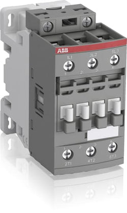
Ordering
1 piece
85364900
Popular Downloads
Dimensions
45 mm
86 mm
86 mm
0.31 kg
Technical
3
0
0
0
3P
IEC/EN 60947-1, IEC/EN 60947-4-1, UL 60335-2-40 LZGH2 A2L, UL 60947-4-1, CSA C22.2 No. 60335-2-40 LZGH2 A2L, CSA C22.2 No. 60947-4-1
Main Circuit 690 V
Control Circuit 50 / 60 Hz
Main Circuit 50 / 60 Hz
Control Circuit 50 / 60 Hz
Main Circuit 50 / 60 Hz
acc. to IEC 60947-4-1, Open Contactors Θ = 40 °C 50 A
(690 V) 40 °C 45 A
(690 V) 60 °C 40 A
(690 V) 70 °C 32 A
(690 V) 40 °C 45 A
(690 V) 60 °C 40 A
(690 V) 70 °C 32 A
(415 V) 60 °C 26 A
(440 V) 60 °C 26 A
(500 V) 60 °C 23 A
(690 V) 60 °C 17 A
(380 / 400 V) 60 °C 26 A
(220 / 230 / 240 V) 60 °C 26 A
(415 V) 60 °C 26 A
(440 V) 60 °C 26 A
(500 V) 60 °C 23 A
(690 V) 60 °C 17 A
(380 / 400 V) 60 °C 26 A
(220 / 230 / 240 V) 60 °C 26 A
(415 V) 60 °C 26 A
(440 V) 60 °C 26 A
(500 V) 60 °C 23 A
(690 V) 60 °C 17 A
(380 / 400 V) 60 °C 26 A
(220 / 230 / 240 V) 60 °C 26 A
(415 V) 60 °C 26 A
(440 V) 60 °C 26 A
(500 V) 60 °C 23 A
(690 V) 60 °C 17 A
(380 / 400 V) 60 °C 26 A
(220 / 230 / 240 V) 60 °C 26 A
(110 V) 2 Poles in Series, 40 °C 45 A
(110 V) 2 Poles in Series, 60 °C 40 A
(110 V) 2 Poles in Series, 70 °C 32 A
(110 V) 3 Poles in Series, 40 °C 45 A
(110 V) 3 Poles in Series, 60 °C 40 A
(110 V) 3 Poles in Series, 70 °C 32 A
(220 V) 3 Poles in Series, 40 °C 45 A
(220 V) 3 Poles in Series, 60 °C 40 A
(220 V) 3 Poles in Series, 70 °C 32 A
(72 V) 1-Pole, 40 °C 45 A
(72 V) 1-Pole, 60 °C 40 A
(72 V) 1-Pole, 70 °C 32 A
(72 V) 2 Poles in Series, 40 °C 45 A
(72 V) 2 Poles in Series, 60 °C 40 A
(72 V) 2 Poles in Series, 70 °C 32 A
(72 V) 3 Poles in Series, 40 °C 45 A
(72 V) 3 Poles in Series, 60 °C 40 A
(72 V) 3 Poles in Series, 70 °C 32 A
(110 V) 2 Poles in Series, 40 °C 45 A
(110 V) 2 Poles in Series, 60 °C 40 A
(110 V) 2 Poles in Series, 70 °C 32 A
(110 V) 3 Poles in Series, 40 °C 45 A
(110 V) 3 Poles in Series, 60 °C 40 A
(110 V) 3 Poles in Series, 70 °C 32 A
(220 V) 3 Poles in Series, 40 °C 45 A
(220 V) 3 Poles in Series, 60 °C 40 A
(220 V) 3 Poles in Series, 70 °C 32 A
(72 V) 1-Pole, 40 °C 45 A
(110 V) 2 Poles in Series, 40 °C 45 A
(110 V) 2 Poles in Series, 60 °C 40 A
(110 V) 2 Poles in Series, 70 °C 32 A
(110 V) 3 Poles in Series, 40 °C 45 A
(110 V) 3 Poles in Series, 60 °C 40 A
(110 V) 3 Poles in Series, 70 °C 32 A
(220 V) 3 Poles in Series, 40 °C 45 A
(220 V) 3 Poles in Series, 60 °C 40 A
(220 V) 3 Poles in Series, 70 °C 32 A
(72 V) 1-Pole, 40 °C 45 A
(72 V) 1-Pole, 60 °C 40 A
(72 V) 1-Pole, 70 °C 32 A
(72 V) 2 Poles in Series, 40 °C 45 A
(72 V) 2 Poles in Series, 60 °C 40 A
(72 V) 2 Poles in Series, 70 °C 32 A
(72 V) 3 Poles in Series, 40 °C 45 A
(72 V) 3 Poles in Series, 60 °C 40 A
(72 V) 3 Poles in Series, 70 °C 32 A
(110 V) 2 Poles in Series, 40 °C 45 A
(110 V) 2 Poles in Series, 60 °C 40 A
(110 V) 2 Poles in Series, 70 °C 32 A
(110 V) 3 Poles in Series, 40 °C 45 A
(110 V) 3 Poles in Series, 60 °C 40 A
(110 V) 3 Poles in Series, 70 °C 32 A
(220 V) 3 Poles in Series, 40 °C 45 A
(220 V) 3 Poles in Series, 60 °C 40 A
(220 V) 3 Poles in Series, 70 °C 32 A
(72 V) 1-Pole, 40 °C 45 A
(110 V) 2 Poles in Series, 40 °C 45 A
(110 V) 2 Poles in Series, 60 °C 40 A
(110 V) 2 Poles in Series, 70 °C 32 A
(110 V) 3 Poles in Series, 40 °C 45 A
(110 V) 3 Poles in Series, 60 °C 40 A
(110 V) 3 Poles in Series, 70 °C 32 A
(220 V) 3 Poles in Series, 40 °C 20 A
(220 V) 3 Poles in Series, 60 °C 20 A
(220 V) 3 Poles in Series, 70 °C 20 A
(72 V) 1-Pole, 40 °C 20 A
(72 V) 1-Pole, 60 °C 20 A
(72 V) 1-Pole, 70 °C 20 A
(72 V) 2 Poles in Series, 40 °C 45 A
(72 V) 2 Poles in Series, 60 °C 40 A
(72 V) 2 Poles in Series, 70 °C 32 A
(72 V) 3 Poles in Series, 40 °C 45 A
(72 V) 3 Poles in Series, 60 °C 40 A
(72 V) 3 Poles in Series, 70 °C 32 A
(110 V) 2 Poles in Series, 40 °C 45 A
(110 V) 2 Poles in Series, 60 °C 40 A
(110 V) 2 Poles in Series, 70 °C 32 A
(110 V) 3 Poles in Series, 40 °C 45 A
(110 V) 3 Poles in Series, 60 °C 40 A
(110 V) 3 Poles in Series, 70 °C 32 A
(220 V) 3 Poles in Series, 40 °C 20 A
(220 V) 3 Poles in Series, 60 °C 20 A
(220 V) 3 Poles in Series, 70 °C 20 A
(72 V) 1-Pole, 40 °C 20 A
(400 V) 11 kW
(415 V) 11 kW
(440 V) 15 kW
(500 V) 15 kW
(690 V) 15 kW
(380 / 400 V) 11 kW
(220 / 230 / 240 V) 6.5 kW
(400 V) 11 kW
(415 V) 11 kW
(440 V) 15 kW
(500 V) 15 kW
(690 V) 15 kW
(380 / 400 V) 11 kW
(220 / 230 / 240 V) 6.5 kW
(415 V) 11 kW
(440 V) 15 kW
(500 V) 15 kW
(690 V) 15 kW
(380 / 400 V) 11 kW
(220 / 230 / 240 V) 6.5 kW
(415 V) 11 kW
(440 V) 15 kW
(500 V) 15 kW
(690 V) 15 kW
(380 / 400 V) 11 kW
(220 / 230 / 240 V) 6.5 kW
at 40 °C Ambient Temp, in Free Air, from a Cold State 10 s 350 A
at 40 °C Ambient Temp, in Free Air, from a Cold State 15 min 50 A
at 40 °C Ambient Temp, in Free Air, from a Cold State 1 min 150 A
at 40 °C Ambient Temp, in Free Air, from a Cold State 1 s 700 A
at 40 °C Ambient Temp, in Free Air, from a Cold State 30 s 225 A
at 40 °C Ambient Temp, in Free Air, from a Cold State 10 s 350 A
at 40 °C Ambient Temp, in Free Air, from a Cold State 15 min 50 A
at 40 °C Ambient Temp, in Free Air, from a Cold State 1 min 150 A
at 40 °C Ambient Temp, in Free Air, from a Cold State 1 s 700 A
at 40 °C Ambient Temp, in Free Air, from a Cold State 30 s 225 A
cos phi=0.45 (cos phi=0.35 for Ie > 100 A) at 440 V 500 A
cos phi=0.45 (cos phi=0.35 for Ie > 100 A) at 690 V 200 A
cos phi=0.45 (cos phi=0.35 for Ie > 100 A) at 440 V 500 A
cos phi=0.45 (cos phi=0.35 for Ie > 100 A) at 690 V 200 A
acc. to IEC 60947-4-1 690 V
acc. to UL/CSA 600 V
acc. to IEC 60947-4-1 690 V
acc. to UL/CSA 600 V
6 kV
(AC-1) 600 cycles per hour
(AC-2 / AC-4) 150 cycles per hour
(AC-3) 1200 cycles per hour
(AC-1) 600 cycles per hour
(AC-2 / AC-4) 150 cycles per hour
(AC-3) 1200 cycles per hour
3600 cycles per hour
50 Hz 48 ... 130 V
60 Hz 48 ... 130 V
DC Operation 48 ... 130 V
50 Hz 48 ... 130 V
60 Hz 48 ... 130 V
DC Operation 48 ... 130 V
at Rated Operating Conditions AC-1 per Pole 1.8 W
at Rated Operating Conditions AC-3 per Pole 0.6 W
at Rated Operating Conditions AC-1 per Pole 1.8 W
at Rated Operating Conditions AC-3 per Pole 0.6 W
Between Coil De-energization and NC Contact Closing 13 ... 98 ms
Between Coil De-energization and NO Contact Opening 11 ... 95 ms
Between Coil Energization and NC Contact Opening 38 ... 90 ms
Between Coil Energization and NO Contact Closing 40 ... 95 ms
Between Coil De-energization and NC Contact Closing 13 ... 98 ms
Between Coil De-energization and NO Contact Opening 11 ... 95 ms
Between Coil Energization and NC Contact Opening 38 ... 90 ms
Between Coil Energization and NO Contact Closing 40 ... 95 ms
TH35-15 (35 x 15 mm Mounting Rail) acc. to IEC 60715
TH35-7.5 (35 x 7.5 mm Mounting Rail) acc. to IEC 60715
TH35-15 (35 x 15 mm Mounting Rail) acc. to IEC 60715
TH35-7.5 (35 x 7.5 mm Mounting Rail) acc. to IEC 60715
2 x M4 Screws Placed Diagonally
Flexible with Ferrule 1/2x 1.5 ... 10 mm²
Flexible with Insulated Ferrule 1x 1.5 ... 10 mm²
Flexible with Insulated Ferrule 2x 1.5 ... 4 mm²
Rigid Solid 1/2x 2.5 ... 4 mm²
Rigid Stranded 1/2x 2.5 ... 10 mm²
Flexible with Ferrule 1/2x 1.5 ... 10 mm²
Flexible with Insulated Ferrule 1x 1.5 ... 10 mm²
Flexible with Insulated Ferrule 2x 1.5 ... 4 mm²
Rigid Solid 1/2x 2.5 ... 4 mm²
Rigid Stranded 1/2x 2.5 ... 10 mm²
Flexible with Ferrule 1/2x 0.75 ... 2.5 mm²
Flexible with Insulated Ferrule 1x 0.75 ... 2.5 mm²
Flexible with Insulated Ferrule 2x 0.75 ... 1.5 mm²
Rigid Solid 1/2x 1 ... 2.5 mm²
Rigid Stranded 1/2x 1 ... 2.5 mm²
Flexible with Ferrule 1/2x 0.75 ... 2.5 mm²
Flexible with Insulated Ferrule 1x 0.75 ... 2.5 mm²
Flexible with Insulated Ferrule 2x 0.75 ... 1.5 mm²
Rigid Solid 1/2x 1 ... 2.5 mm²
Rigid Stranded 1/2x 1 ... 2.5 mm²
Control Circuit 10 mm
Main Circuit 14 mm
Control Circuit 10 mm
Main Circuit 14 mm
acc. to IEC 60529, IEC 60947-1, EN 60529 Coil Terminals IP20
acc. to IEC 60529, IEC 60947-1, EN 60529 Main Terminals IP20
acc. to IEC 60529, IEC 60947-1, EN 60529 Coil Terminals IP20
acc. to IEC 60529, IEC 60947-1, EN 60529 Main Terminals IP20
Control Circuit 1.2 N·m
Main Circuit 2.5 N·m
Control Circuit 1.2 N·m
Main Circuit 2.5 N·m
Screw Terminals
Block Contactor
Technical UL/CSA
1
27 A
(115 V AC) Single Phase 2 Hp
(200 V AC) Three Phase 7-1/2 Hp
(230 V AC) Single Phase 3 Hp
(230 V AC) Three Phase 7-1/2 Hp
(460 V AC) Three Phase 10 Hp
(575 V AC) Three Phase 10 Hp
(115 V AC) Single Phase 2 Hp
(200 V AC) Three Phase 7-1/2 Hp
(230 V AC) Single Phase 3 Hp
(230 V AC) Three Phase 7-1/2 Hp
(460 V AC) Three Phase 10 Hp
(575 V AC) Three Phase 10 Hp
Main Circuit 600 V
(600 V AC) 45 A
(120 V AC) Single Phase 2 hp
(200 ... 208 V AC) Three Phase 7-1/2 hp
(220 ... 240 V AC) Three Phase 7-1/2 hp
(240 V AC) Single Phase 3 hp
(440 ... 480 V AC) Three Phase 15 hp
(550 ... 600 V AC) Three Phase 20 hp
(120 V AC) Single Phase 2 hp
(200 ... 208 V AC) Three Phase 7-1/2 hp
(220 ... 240 V AC) Three Phase 7-1/2 hp
(240 V AC) Single Phase 3 hp
(440 ... 480 V AC) Three Phase 15 hp
(550 ... 600 V AC) Three Phase 20 hp
Rigid Solid 1/2x 14-10 AWG
Rigid Stranded 1/2x 14-8 AWG
Rigid Solid 1/2x 14-10 AWG
Rigid Stranded 1/2x 14-8 AWG
Rigid Solid 1/2x 18-14 AWG
Rigid Stranded 1/2x 18-14 AWG
Rigid Solid 1/2x 18-14 AWG
Rigid Stranded 1/2x 18-14 AWG
Control Circuit 11 in·lb
Main Circuit 22 in·lb
Control Circuit 11 in·lb
Main Circuit 22 in·lb
(120 V AC) Single Phase 24 A
(200 ... 208 V AC) Three Phase 25.3 A
(220 ... 240 V AC) Three Phase 22 A
(240 V AC) Single Phase 17 A
(440 ... 480 V AC) Three Phase 21 A
(550 ... 600 V AC) Three Phase 22 A
(120 V AC) Single Phase 24 A
(200 ... 208 V AC) Three Phase 25.3 A
(220 ... 240 V AC) Three Phase 22 A
(240 V AC) Single Phase 17 A
(440 ... 480 V AC) Three Phase 21 A
(550 ... 600 V AC) Three Phase 22 A
Environmental
Close to Contactor Fitted with Thermal O/L Relay -25 ... 60 °C
Close to Contactor without Thermal O/L Relay -40 ... 70 °C
Close to Contactor for Storage -60 ... +80 °C
Close to Contactor Fitted with Thermal O/L Relay -25 ... 60 °C
Close to Contactor without Thermal O/L Relay -40 ... 70 °C
Close to Contactor for Storage -60 ... +80 °C
Category B according to IEC 60947-1 Annex Q
Without Derating 3000 m
Closed, Shock Direction: B1 25 g
Open, Shock Direction: B1 5 g
Shock Direction: A 30 g
Shock Direction: B2 15 g
Shock Direction: C1 25 g
Shock Direction: C2 25 g
Closed, Shock Direction: B1 25 g
Open, Shock Direction: B1 5 g
Shock Direction: A 30 g
Shock Direction: B2 15 g
Shock Direction: C1 25 g
Shock Direction: C2 25 g
4g Closed Position & 2g Open position 5 ... 300 Hz
3
Material Compliance
Following EU Directive 2011/65/EU and Amendment 2015/863 July 22, 2019
2a28af85-35e0-4f2d-82a4-95a3b8101af1 China
9bfa6f5c-e9ce-41b4-a412-4d185f3ca6a9 France
a6b1f851-61a9-4f51-bc9c-ea44040c98ea Belgium
ec66baca-5c4f-4660-aedc-e8fe2be351a9 Hungary
591d22cb-516f-4cf9-81d2-a12d1b2c03f4 Germany
53747ebd-ed6c-46cd-8f94-b5f28b032c41 Sweden
dd6f016c-647c-45c5-9479-c676bc3af14c Poland
b0d95733-16ab-4405-8252-354423a079e9 France
6077ef9c-1429-47b0-b1b2-ea5e0f8215f7 Sweden
5e6608bc-17e2-44f6-8225-598e40341ffb Portugal
f544f66c-8a1d-45bf-b23e-6f2783f17fcf Bulgaria
9370606d-ee74-4e62-9e63-e7399b32058c Germany
56c32c56-d518-4c69-85e5-20a6ab4d82fc Hungary
8e9defbb-ed4f-4f51-b9db-9c053b314182 Estonia
538f7abb-24e4-495e-b9b6-a985e95ab556 Netherlands
b546d25a-b2ad-4035-8f91-4c2b0debe186 Poland
e0154190-1485-4fcb-8bd1-288bfbf90ff2 Greece
369c922b-d122-4b35-a77f-503fba571834 Norway
3d5ac123-c4d1-4896-9a68-87e602ad74e4 Finland
2562240a-61f1-4fb1-937a-980ec3caac7f Germany
d4e89531-26c7-4b39-899c-df8bc57d3065 Czech Republic
564ac986-7ea9-4847-8b97-9679eccc71ae Poland
9b0b133f-3be0-415f-8e95-b35dc5a6ba57 Spain
48461228-5649-417d-be34-a3911865419a Belgium
5d3b6801-71be-4866-8fb1-a1445355ee80 Croatia
5fce13fe-05a5-4e34-88e7-c6ec2d73cf7d Germany
fa009bb1-5ab7-41b0-a1a0-b54eef6f6b2e Germany
87abcebe-6303-42c4-b1b1-35f5636dcff2 Denmark
9bfa6f5c-e9ce-41b4-a412-4d185f3ca6a9 France
a6b1f851-61a9-4f51-bc9c-ea44040c98ea Belgium
ec66baca-5c4f-4660-aedc-e8fe2be351a9 Hungary
591d22cb-516f-4cf9-81d2-a12d1b2c03f4 Germany
53747ebd-ed6c-46cd-8f94-b5f28b032c41 Sweden
dd6f016c-647c-45c5-9479-c676bc3af14c Poland
b0d95733-16ab-4405-8252-354423a079e9 France
6077ef9c-1429-47b0-b1b2-ea5e0f8215f7 Sweden
5e6608bc-17e2-44f6-8225-598e40341ffb Portugal
f544f66c-8a1d-45bf-b23e-6f2783f17fcf Bulgaria
Business To Business
5. Small Equipment (No External Dimension More Than 50 cm)
ABB EcoSolutions
Recycled Cardboard - 86 %
Recycled Metal - 28 %
Certificates and Declarations
Container Information
box 1 piece
87 mm
87 mm
47 mm
0.31 kg
3471523110922
box 21 piece
250 mm
300 mm
315 mm
6.51 kg
External Classifications and Standards
Q
EC000066 - Power contactor, AC switching
EC000066 - Power contactor, AC switching
EC000066 - Power contactor, AC switching
V11.0 : 27371003
39121529
4758 >> Iec Contactors
3706263
3211377

Ordering
1 piece
85364900
Popular Downloads
Dimensions
45 mm
86 mm
86 mm
0.31 kg
Technical
3
0
0
0
3P
IEC/EN 60947-1, IEC/EN 60947-4-1, UL 60335-2-40 LZGH2 A2L, UL 60947-4-1, CSA C22.2 No. 60335-2-40 LZGH2 A2L, CSA C22.2 No. 60947-4-1
Main Circuit 690 V
Control Circuit 50 / 60 Hz
Main Circuit 50 / 60 Hz
Control Circuit 50 / 60 Hz
Main Circuit 50 / 60 Hz
acc. to IEC 60947-4-1, Open Contactors Θ = 40 °C 50 A
(690 V) 40 °C 45 A
(690 V) 60 °C 40 A
(690 V) 70 °C 32 A
(690 V) 40 °C 45 A
(690 V) 60 °C 40 A
(690 V) 70 °C 32 A
(415 V) 60 °C 26 A
(440 V) 60 °C 26 A
(500 V) 60 °C 23 A
(690 V) 60 °C 17 A
(380 / 400 V) 60 °C 26 A
(220 / 230 / 240 V) 60 °C 26 A
(415 V) 60 °C 26 A
(440 V) 60 °C 26 A
(500 V) 60 °C 23 A
(690 V) 60 °C 17 A
(380 / 400 V) 60 °C 26 A
(220 / 230 / 240 V) 60 °C 26 A
(415 V) 60 °C 26 A
(440 V) 60 °C 26 A
(500 V) 60 °C 23 A
(690 V) 60 °C 17 A
(380 / 400 V) 60 °C 26 A
(220 / 230 / 240 V) 60 °C 26 A
(415 V) 60 °C 26 A
(440 V) 60 °C 26 A
(500 V) 60 °C 23 A
(690 V) 60 °C 17 A
(380 / 400 V) 60 °C 26 A
(220 / 230 / 240 V) 60 °C 26 A
(110 V) 2 Poles in Series, 40 °C 45 A
(110 V) 2 Poles in Series, 60 °C 40 A
(110 V) 2 Poles in Series, 70 °C 32 A
(110 V) 3 Poles in Series, 40 °C 45 A
(110 V) 3 Poles in Series, 60 °C 40 A
(110 V) 3 Poles in Series, 70 °C 32 A
(220 V) 3 Poles in Series, 40 °C 45 A
(220 V) 3 Poles in Series, 60 °C 40 A
(220 V) 3 Poles in Series, 70 °C 32 A
(72 V) 1-Pole, 40 °C 45 A
(72 V) 1-Pole, 60 °C 40 A
(72 V) 1-Pole, 70 °C 32 A
(72 V) 2 Poles in Series, 40 °C 45 A
(72 V) 2 Poles in Series, 60 °C 40 A
(72 V) 2 Poles in Series, 70 °C 32 A
(72 V) 3 Poles in Series, 40 °C 45 A
(72 V) 3 Poles in Series, 60 °C 40 A
(72 V) 3 Poles in Series, 70 °C 32 A
(110 V) 2 Poles in Series, 40 °C 45 A
(110 V) 2 Poles in Series, 60 °C 40 A
(110 V) 2 Poles in Series, 70 °C 32 A
(110 V) 3 Poles in Series, 40 °C 45 A
(110 V) 3 Poles in Series, 60 °C 40 A
(110 V) 3 Poles in Series, 70 °C 32 A
(220 V) 3 Poles in Series, 40 °C 45 A
(220 V) 3 Poles in Series, 60 °C 40 A
(220 V) 3 Poles in Series, 70 °C 32 A
(72 V) 1-Pole, 40 °C 45 A
(110 V) 2 Poles in Series, 40 °C 45 A
(110 V) 2 Poles in Series, 60 °C 40 A
(110 V) 2 Poles in Series, 70 °C 32 A
(110 V) 3 Poles in Series, 40 °C 45 A
(110 V) 3 Poles in Series, 60 °C 40 A
(110 V) 3 Poles in Series, 70 °C 32 A
(220 V) 3 Poles in Series, 40 °C 45 A
(220 V) 3 Poles in Series, 60 °C 40 A
(220 V) 3 Poles in Series, 70 °C 32 A
(72 V) 1-Pole, 40 °C 45 A
(72 V) 1-Pole, 60 °C 40 A
(72 V) 1-Pole, 70 °C 32 A
(72 V) 2 Poles in Series, 40 °C 45 A
(72 V) 2 Poles in Series, 60 °C 40 A
(72 V) 2 Poles in Series, 70 °C 32 A
(72 V) 3 Poles in Series, 40 °C 45 A
(72 V) 3 Poles in Series, 60 °C 40 A
(72 V) 3 Poles in Series, 70 °C 32 A
(110 V) 2 Poles in Series, 40 °C 45 A
(110 V) 2 Poles in Series, 60 °C 40 A
(110 V) 2 Poles in Series, 70 °C 32 A
(110 V) 3 Poles in Series, 40 °C 45 A
(110 V) 3 Poles in Series, 60 °C 40 A
(110 V) 3 Poles in Series, 70 °C 32 A
(220 V) 3 Poles in Series, 40 °C 45 A
(220 V) 3 Poles in Series, 60 °C 40 A
(220 V) 3 Poles in Series, 70 °C 32 A
(72 V) 1-Pole, 40 °C 45 A
(110 V) 2 Poles in Series, 40 °C 45 A
(110 V) 2 Poles in Series, 60 °C 40 A
(110 V) 2 Poles in Series, 70 °C 32 A
(110 V) 3 Poles in Series, 40 °C 45 A
(110 V) 3 Poles in Series, 60 °C 40 A
(110 V) 3 Poles in Series, 70 °C 32 A
(220 V) 3 Poles in Series, 40 °C 20 A
(220 V) 3 Poles in Series, 60 °C 20 A
(220 V) 3 Poles in Series, 70 °C 20 A
(72 V) 1-Pole, 40 °C 20 A
(72 V) 1-Pole, 60 °C 20 A
(72 V) 1-Pole, 70 °C 20 A
(72 V) 2 Poles in Series, 40 °C 45 A
(72 V) 2 Poles in Series, 60 °C 40 A
(72 V) 2 Poles in Series, 70 °C 32 A
(72 V) 3 Poles in Series, 40 °C 45 A
(72 V) 3 Poles in Series, 60 °C 40 A
(72 V) 3 Poles in Series, 70 °C 32 A
(110 V) 2 Poles in Series, 40 °C 45 A
(110 V) 2 Poles in Series, 60 °C 40 A
(110 V) 2 Poles in Series, 70 °C 32 A
(110 V) 3 Poles in Series, 40 °C 45 A
(110 V) 3 Poles in Series, 60 °C 40 A
(110 V) 3 Poles in Series, 70 °C 32 A
(220 V) 3 Poles in Series, 40 °C 20 A
(220 V) 3 Poles in Series, 60 °C 20 A
(220 V) 3 Poles in Series, 70 °C 20 A
(72 V) 1-Pole, 40 °C 20 A
(400 V) 11 kW
(415 V) 11 kW
(440 V) 15 kW
(500 V) 15 kW
(690 V) 15 kW
(380 / 400 V) 11 kW
(220 / 230 / 240 V) 6.5 kW
(400 V) 11 kW
(415 V) 11 kW
(440 V) 15 kW
(500 V) 15 kW
(690 V) 15 kW
(380 / 400 V) 11 kW
(220 / 230 / 240 V) 6.5 kW
(415 V) 11 kW
(440 V) 15 kW
(500 V) 15 kW
(690 V) 15 kW
(380 / 400 V) 11 kW
(220 / 230 / 240 V) 6.5 kW
(415 V) 11 kW
(440 V) 15 kW
(500 V) 15 kW
(690 V) 15 kW
(380 / 400 V) 11 kW
(220 / 230 / 240 V) 6.5 kW
at 40 °C Ambient Temp, in Free Air, from a Cold State 10 s 350 A
at 40 °C Ambient Temp, in Free Air, from a Cold State 15 min 50 A
at 40 °C Ambient Temp, in Free Air, from a Cold State 1 min 150 A
at 40 °C Ambient Temp, in Free Air, from a Cold State 1 s 700 A
at 40 °C Ambient Temp, in Free Air, from a Cold State 30 s 225 A
at 40 °C Ambient Temp, in Free Air, from a Cold State 10 s 350 A
at 40 °C Ambient Temp, in Free Air, from a Cold State 15 min 50 A
at 40 °C Ambient Temp, in Free Air, from a Cold State 1 min 150 A
at 40 °C Ambient Temp, in Free Air, from a Cold State 1 s 700 A
at 40 °C Ambient Temp, in Free Air, from a Cold State 30 s 225 A
cos phi=0.45 (cos phi=0.35 for Ie > 100 A) at 440 V 500 A
cos phi=0.45 (cos phi=0.35 for Ie > 100 A) at 690 V 200 A
cos phi=0.45 (cos phi=0.35 for Ie > 100 A) at 440 V 500 A
cos phi=0.45 (cos phi=0.35 for Ie > 100 A) at 690 V 200 A
acc. to IEC 60947-4-1 690 V
acc. to UL/CSA 600 V
acc. to IEC 60947-4-1 690 V
acc. to UL/CSA 600 V
6 kV
(AC-1) 600 cycles per hour
(AC-2 / AC-4) 150 cycles per hour
(AC-3) 1200 cycles per hour
(AC-1) 600 cycles per hour
(AC-2 / AC-4) 150 cycles per hour
(AC-3) 1200 cycles per hour
3600 cycles per hour
50 Hz 100 ... 250 V
60 Hz 100 ... 250 V
DC Operation 100 ... 250 V
50 Hz 100 ... 250 V
60 Hz 100 ... 250 V
DC Operation 100 ... 250 V
at Rated Operating Conditions AC-1 per Pole 1.8 W
at Rated Operating Conditions AC-3 per Pole 0.6 W
at Rated Operating Conditions AC-1 per Pole 1.8 W
at Rated Operating Conditions AC-3 per Pole 0.6 W
Between Coil De-energization and NC Contact Closing 13 ... 98 ms
Between Coil De-energization and NO Contact Opening 11 ... 95 ms
Between Coil Energization and NC Contact Opening 38 ... 90 ms
Between Coil Energization and NO Contact Closing 40 ... 95 ms
Between Coil De-energization and NC Contact Closing 13 ... 98 ms
Between Coil De-energization and NO Contact Opening 11 ... 95 ms
Between Coil Energization and NC Contact Opening 38 ... 90 ms
Between Coil Energization and NO Contact Closing 40 ... 95 ms
TH35-15 (35 x 15 mm Mounting Rail) acc. to IEC 60715
TH35-7.5 (35 x 7.5 mm Mounting Rail) acc. to IEC 60715
TH35-15 (35 x 15 mm Mounting Rail) acc. to IEC 60715
TH35-7.5 (35 x 7.5 mm Mounting Rail) acc. to IEC 60715
2 x M4 Screws Placed Diagonally
Flexible with Ferrule 1/2x 1.5 ... 10 mm²
Flexible with Insulated Ferrule 1x 1.5 ... 10 mm²
Flexible with Insulated Ferrule 2x 1.5 ... 4 mm²
Rigid Solid 1/2x 2.5 ... 4 mm²
Rigid Stranded 1/2x 2.5 ... 10 mm²
Flexible with Ferrule 1/2x 1.5 ... 10 mm²
Flexible with Insulated Ferrule 1x 1.5 ... 10 mm²
Flexible with Insulated Ferrule 2x 1.5 ... 4 mm²
Rigid Solid 1/2x 2.5 ... 4 mm²
Rigid Stranded 1/2x 2.5 ... 10 mm²
Flexible with Ferrule 1/2x 0.75 ... 2.5 mm²
Flexible with Insulated Ferrule 1x 0.75 ... 2.5 mm²
Flexible with Insulated Ferrule 2x 0.75 ... 1.5 mm²
Rigid Solid 1/2x 1 ... 2.5 mm²
Rigid Stranded 1/2x 1 ... 2.5 mm²
Flexible with Ferrule 1/2x 0.75 ... 2.5 mm²
Flexible with Insulated Ferrule 1x 0.75 ... 2.5 mm²
Flexible with Insulated Ferrule 2x 0.75 ... 1.5 mm²
Rigid Solid 1/2x 1 ... 2.5 mm²
Rigid Stranded 1/2x 1 ... 2.5 mm²
Control Circuit 10 mm
Main Circuit 14 mm
Control Circuit 10 mm
Main Circuit 14 mm
acc. to IEC 60529, IEC 60947-1, EN 60529 Coil Terminals IP20
acc. to IEC 60529, IEC 60947-1, EN 60529 Main Terminals IP20
acc. to IEC 60529, IEC 60947-1, EN 60529 Coil Terminals IP20
acc. to IEC 60529, IEC 60947-1, EN 60529 Main Terminals IP20
Control Circuit 1.2 N·m
Main Circuit 2.5 N·m
Control Circuit 1.2 N·m
Main Circuit 2.5 N·m
Screw Terminals
Block Contactor
Technical UL/CSA
1
27 A
(115 V AC) Single Phase 2 Hp
(200 V AC) Three Phase 7-1/2 Hp
(230 V AC) Single Phase 3 Hp
(230 V AC) Three Phase 7-1/2 Hp
(460 V AC) Three Phase 10 Hp
(575 V AC) Three Phase 10 Hp
(115 V AC) Single Phase 2 Hp
(200 V AC) Three Phase 7-1/2 Hp
(230 V AC) Single Phase 3 Hp
(230 V AC) Three Phase 7-1/2 Hp
(460 V AC) Three Phase 10 Hp
(575 V AC) Three Phase 10 Hp
Main Circuit 600 V
(600 V AC) 45 A
(120 V AC) Single Phase 2 hp
(200 ... 208 V AC) Three Phase 7-1/2 hp
(220 ... 240 V AC) Three Phase 7-1/2 hp
(240 V AC) Single Phase 3 hp
(440 ... 480 V AC) Three Phase 15 hp
(550 ... 600 V AC) Three Phase 20 hp
(120 V AC) Single Phase 2 hp
(200 ... 208 V AC) Three Phase 7-1/2 hp
(220 ... 240 V AC) Three Phase 7-1/2 hp
(240 V AC) Single Phase 3 hp
(440 ... 480 V AC) Three Phase 15 hp
(550 ... 600 V AC) Three Phase 20 hp
Rigid Solid 1/2x 14-10 AWG
Rigid Stranded 1/2x 14-8 AWG
Rigid Solid 1/2x 14-10 AWG
Rigid Stranded 1/2x 14-8 AWG
Rigid Solid 1/2x 18-14 AWG
Rigid Stranded 1/2x 18-14 AWG
Rigid Solid 1/2x 18-14 AWG
Rigid Stranded 1/2x 18-14 AWG
Control Circuit 11 in·lb
Main Circuit 22 in·lb
Control Circuit 11 in·lb
Main Circuit 22 in·lb
(120 V AC) Single Phase 24 A
(200 ... 208 V AC) Three Phase 25.3 A
(220 ... 240 V AC) Three Phase 22 A
(240 V AC) Single Phase 17 A
(440 ... 480 V AC) Three Phase 21 A
(550 ... 600 V AC) Three Phase 22 A
(120 V AC) Single Phase 24 A
(200 ... 208 V AC) Three Phase 25.3 A
(220 ... 240 V AC) Three Phase 22 A
(240 V AC) Single Phase 17 A
(440 ... 480 V AC) Three Phase 21 A
(550 ... 600 V AC) Three Phase 22 A
Environmental
Close to Contactor Fitted with Thermal O/L Relay -25 ... 60 °C
Close to Contactor without Thermal O/L Relay -40 ... 70 °C
Close to Contactor for Storage -60 ... +80 °C
Close to Contactor Fitted with Thermal O/L Relay -25 ... 60 °C
Close to Contactor without Thermal O/L Relay -40 ... 70 °C
Close to Contactor for Storage -60 ... +80 °C
Category B according to IEC 60947-1 Annex Q
Without Derating 3000 m
Closed, Shock Direction: B1 25 g
Open, Shock Direction: B1 5 g
Shock Direction: A 30 g
Shock Direction: B2 15 g
Shock Direction: C1 25 g
Shock Direction: C2 25 g
Closed, Shock Direction: B1 25 g
Open, Shock Direction: B1 5 g
Shock Direction: A 30 g
Shock Direction: B2 15 g
Shock Direction: C1 25 g
Shock Direction: C2 25 g
4g Closed Position & 2g Open position 5 ... 300 Hz
3
Material Compliance
Following EU Directive 2011/65/EU and Amendment 2015/863 July 22, 2019
7ecf2e54-f412-43b8-a8b6-f76449ceacf0 China
9d16e54f-6686-406e-b14f-0cee1717e24b Estonia
37f3e77c-795e-41ee-b433-5c1794ce6c9f Norway
c4403672-cc97-4b2d-a454-093c5bdbe0cb Poland
cfb0408b-ba9b-48ab-901c-b020f8b19980 Poland
50053f28-5503-45f1-9216-9c6153ff7c92 Croatia
6b0d03d8-ef7c-4172-83cb-7d93cddc8742 Germany
ed8aca28-3375-4793-aa35-19886c194ca8 Czech Republic
c2440a4a-0fc3-4333-b049-16519c9881df Hungary
9d2c81de-3f4d-4249-a51b-c1b177e19539 Belgium
afa8983c-e5a2-4fde-b1d7-6bf2e8d96c79 Sweden
485bc883-a6ce-4552-a15a-da10257b9607 France
14d33d6f-4b5e-4e0e-b342-8cfc4ba5a2c9 Poland
b8c1ba93-f584-410e-92b8-54d0ba47a423 Germany
de3d8d83-9e65-4128-8963-0d0484118cb3 France
531e9494-6c9c-4abc-a5af-da0b16b0f7ef Germany
8233522d-460d-47d7-a4cd-1e65521b7d63 Germany
2cfe5e3d-3504-4045-864e-2829c08e0738 Denmark
5e33d089-78e4-4d6b-8056-dd2f81a6aacc Sweden
30aa3dc6-6fdb-459e-845e-8598288ccde5 Germany
4aefcb2d-c513-4f5e-a9a4-32a65a38d38f Portugal
494382ca-a4c6-41e3-a2ba-63b24bdfff79 Belgium
d41d1cf2-832c-4c8c-b21b-2c05c687541b Greece
41a24e46-e6a4-4f72-b9d0-f89775cf0a5f Bulgaria
ce0aed02-bd40-49e4-b9b4-cfd41985524a Hungary
b07f208c-c45d-421b-8981-bfcef052fa0d Netherlands
c2dff4eb-46ff-42c4-a65b-a1a9ee75a19d Spain
24fc9fcb-5e79-463c-963b-c3d91fa717e5 Finland
9d16e54f-6686-406e-b14f-0cee1717e24b Estonia
37f3e77c-795e-41ee-b433-5c1794ce6c9f Norway
c4403672-cc97-4b2d-a454-093c5bdbe0cb Poland
cfb0408b-ba9b-48ab-901c-b020f8b19980 Poland
50053f28-5503-45f1-9216-9c6153ff7c92 Croatia
6b0d03d8-ef7c-4172-83cb-7d93cddc8742 Germany
ed8aca28-3375-4793-aa35-19886c194ca8 Czech Republic
c2440a4a-0fc3-4333-b049-16519c9881df Hungary
9d2c81de-3f4d-4249-a51b-c1b177e19539 Belgium
afa8983c-e5a2-4fde-b1d7-6bf2e8d96c79 Sweden
Business To Business
5. Small Equipment (No External Dimension More Than 50 cm)
ABB EcoSolutions
Recycled Cardboard - 86 %
Recycled Metal - 28 %
Certificates and Declarations
Container Information
box 1 piece
87 mm
87 mm
47 mm
0.31 kg
3471523110939
box 21 piece
250 mm
300 mm
315 mm
6.51 kg
External Classifications and Standards
Q
EC000066 - Power contactor, AC switching
EC000066 - Power contactor, AC switching
EC000066 - Power contactor, AC switching
V11.0 : 27371003
39121529
4758 >> Iec Contactors
3706264
3211378
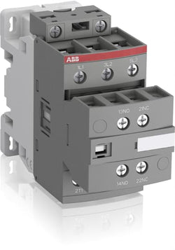
Ordering
1 piece
85364900
Popular Downloads
Dimensions
45 mm
111.5 mm
86 mm
0.35 kg
Technical
3
0
1
1
3P
IEC/EN 60947-1, IEC/EN 60947-4-1, UL 60335-2-40 LZGH2 A2L, UL 60947-4-1, CSA C22.2 No. 60335-2-40 LZGH2 A2L, CSA C22.2 No. 60947-4-1
Auxiliary Circuit 690 V
Main Circuit 690 V
Auxiliary Circuit 690 V
Main Circuit 690 V
Auxiliary Circuit 50 / 60 Hz
Control Circuit 50 / 60 Hz
Main Circuit 50 / 60 Hz
Auxiliary Circuit 50 / 60 Hz
Control Circuit 50 / 60 Hz
Main Circuit 50 / 60 Hz
acc. to IEC 60947-4-1, Open Contactors Θ = 40 °C 50 A
acc. to IEC 60947-5-1, Θ = 40 °C 16 A
acc. to IEC 60947-4-1, Open Contactors Θ = 40 °C 50 A
acc. to IEC 60947-5-1, Θ = 40 °C 16 A
(690 V) 40 °C 45 A
(690 V) 60 °C 40 A
(690 V) 70 °C 32 A
(690 V) 40 °C 45 A
(690 V) 60 °C 40 A
(690 V) 70 °C 32 A
(415 V) 60 °C 26 A
(440 V) 60 °C 26 A
(500 V) 60 °C 23 A
(690 V) 60 °C 17 A
(380 / 400 V) 60 °C 26 A
(220 / 230 / 240 V) 60 °C 26 A
(415 V) 60 °C 26 A
(440 V) 60 °C 26 A
(500 V) 60 °C 23 A
(690 V) 60 °C 17 A
(380 / 400 V) 60 °C 26 A
(220 / 230 / 240 V) 60 °C 26 A
(415 V) 60 °C 26 A
(440 V) 60 °C 26 A
(500 V) 60 °C 23 A
(690 V) 60 °C 17 A
(380 / 400 V) 60 °C 26 A
(220 / 230 / 240 V) 60 °C 26 A
(415 V) 60 °C 26 A
(440 V) 60 °C 26 A
(500 V) 60 °C 23 A
(690 V) 60 °C 17 A
(380 / 400 V) 60 °C 26 A
(220 / 230 / 240 V) 60 °C 26 A
(500 V) 2 A
(690 V) 2 A
(24 / 127 V) 6 A
(220 / 240 V) 4 A
(400 / 440 V) 3 A
(500 V) 2 A
(690 V) 2 A
(24 / 127 V) 6 A
(220 / 240 V) 4 A
(400 / 440 V) 3 A
(110 V) 2 Poles in Series, 40 °C 45 A
(110 V) 2 Poles in Series, 60 °C 40 A
(110 V) 2 Poles in Series, 70 °C 32 A
(110 V) 3 Poles in Series, 40 °C 45 A
(110 V) 3 Poles in Series, 60 °C 40 A
(110 V) 3 Poles in Series, 70 °C 32 A
(220 V) 3 Poles in Series, 40 °C 45 A
(220 V) 3 Poles in Series, 60 °C 40 A
(220 V) 3 Poles in Series, 70 °C 32 A
(72 V) 1-Pole, 40 °C 45 A
(72 V) 1-Pole, 60 °C 40 A
(72 V) 1-Pole, 70 °C 32 A
(72 V) 2 Poles in Series, 40 °C 45 A
(72 V) 2 Poles in Series, 60 °C 40 A
(72 V) 2 Poles in Series, 70 °C 32 A
(72 V) 3 Poles in Series, 40 °C 45 A
(72 V) 3 Poles in Series, 60 °C 40 A
(72 V) 3 Poles in Series, 70 °C 32 A
(110 V) 2 Poles in Series, 40 °C 45 A
(110 V) 2 Poles in Series, 60 °C 40 A
(110 V) 2 Poles in Series, 70 °C 32 A
(110 V) 3 Poles in Series, 40 °C 45 A
(110 V) 3 Poles in Series, 60 °C 40 A
(110 V) 3 Poles in Series, 70 °C 32 A
(220 V) 3 Poles in Series, 40 °C 45 A
(220 V) 3 Poles in Series, 60 °C 40 A
(220 V) 3 Poles in Series, 70 °C 32 A
(72 V) 1-Pole, 40 °C 45 A
(110 V) 2 Poles in Series, 40 °C 45 A
(110 V) 2 Poles in Series, 60 °C 40 A
(110 V) 2 Poles in Series, 70 °C 32 A
(110 V) 3 Poles in Series, 40 °C 45 A
(110 V) 3 Poles in Series, 60 °C 40 A
(110 V) 3 Poles in Series, 70 °C 32 A
(220 V) 3 Poles in Series, 40 °C 45 A
(220 V) 3 Poles in Series, 60 °C 40 A
(220 V) 3 Poles in Series, 70 °C 32 A
(72 V) 1-Pole, 40 °C 45 A
(72 V) 1-Pole, 60 °C 40 A
(72 V) 1-Pole, 70 °C 32 A
(72 V) 2 Poles in Series, 40 °C 45 A
(72 V) 2 Poles in Series, 60 °C 40 A
(72 V) 2 Poles in Series, 70 °C 32 A
(72 V) 3 Poles in Series, 40 °C 45 A
(72 V) 3 Poles in Series, 60 °C 40 A
(72 V) 3 Poles in Series, 70 °C 32 A
(110 V) 2 Poles in Series, 40 °C 45 A
(110 V) 2 Poles in Series, 60 °C 40 A
(110 V) 2 Poles in Series, 70 °C 32 A
(110 V) 3 Poles in Series, 40 °C 45 A
(110 V) 3 Poles in Series, 60 °C 40 A
(110 V) 3 Poles in Series, 70 °C 32 A
(220 V) 3 Poles in Series, 40 °C 45 A
(220 V) 3 Poles in Series, 60 °C 40 A
(220 V) 3 Poles in Series, 70 °C 32 A
(72 V) 1-Pole, 40 °C 45 A
(110 V) 2 Poles in Series, 40 °C 45 A
(110 V) 2 Poles in Series, 60 °C 40 A
(110 V) 2 Poles in Series, 70 °C 32 A
(110 V) 3 Poles in Series, 40 °C 45 A
(110 V) 3 Poles in Series, 60 °C 40 A
(110 V) 3 Poles in Series, 70 °C 32 A
(220 V) 3 Poles in Series, 40 °C 20 A
(220 V) 3 Poles in Series, 60 °C 20 A
(220 V) 3 Poles in Series, 70 °C 20 A
(72 V) 1-Pole, 40 °C 20 A
(72 V) 1-Pole, 60 °C 20 A
(72 V) 1-Pole, 70 °C 20 A
(72 V) 2 Poles in Series, 40 °C 45 A
(72 V) 2 Poles in Series, 60 °C 40 A
(72 V) 2 Poles in Series, 70 °C 32 A
(72 V) 3 Poles in Series, 40 °C 45 A
(72 V) 3 Poles in Series, 60 °C 40 A
(72 V) 3 Poles in Series, 70 °C 32 A
(110 V) 2 Poles in Series, 40 °C 45 A
(110 V) 2 Poles in Series, 60 °C 40 A
(110 V) 2 Poles in Series, 70 °C 32 A
(110 V) 3 Poles in Series, 40 °C 45 A
(110 V) 3 Poles in Series, 60 °C 40 A
(110 V) 3 Poles in Series, 70 °C 32 A
(220 V) 3 Poles in Series, 40 °C 20 A
(220 V) 3 Poles in Series, 60 °C 20 A
(220 V) 3 Poles in Series, 70 °C 20 A
(72 V) 1-Pole, 40 °C 20 A
(24 V) 6 A / 144 W
(48 V) 2.8 A / 134 W
(72 V) 1 A / 72 W
(110 V) 0.55 A / 60 W
(125 V) 0.55 A / 69 W
(220 V) 0.27 A / 60 W
(250 V) 0.27 A / 68 W
(400 V) 0.15 A / 60 W
(500 V) 0.13 A / 65 W
(600 V) 0.1 A / 60 W
(24 V) 6 A / 144 W
(48 V) 2.8 A / 134 W
(72 V) 1 A / 72 W
(110 V) 0.55 A / 60 W
(125 V) 0.55 A / 69 W
(220 V) 0.27 A / 60 W
(250 V) 0.27 A / 68 W
(400 V) 0.15 A / 60 W
(500 V) 0.13 A / 65 W
(600 V) 0.1 A / 60 W
(400 V) 11 kW
(415 V) 11 kW
(440 V) 15 kW
(500 V) 15 kW
(690 V) 15 kW
(380 / 400 V) 11 kW
(220 / 230 / 240 V) 6.5 kW
(400 V) 11 kW
(415 V) 11 kW
(440 V) 15 kW
(500 V) 15 kW
(690 V) 15 kW
(380 / 400 V) 11 kW
(220 / 230 / 240 V) 6.5 kW
(415 V) 11 kW
(440 V) 15 kW
(500 V) 15 kW
(690 V) 15 kW
(380 / 400 V) 11 kW
(220 / 230 / 240 V) 6.5 kW
(415 V) 11 kW
(440 V) 15 kW
(500 V) 15 kW
(690 V) 15 kW
(380 / 400 V) 11 kW
(220 / 230 / 240 V) 6.5 kW
at 40 °C Ambient Temp, in Free Air, from a Cold State 10 s 350 A
at 40 °C Ambient Temp, in Free Air, from a Cold State 15 min 50 A
at 40 °C Ambient Temp, in Free Air, from a Cold State 1 min 150 A
at 40 °C Ambient Temp, in Free Air, from a Cold State 1 s 700 A
at 40 °C Ambient Temp, in Free Air, from a Cold State 30 s 225 A
for 0.1 s 140 A
for 1 s 100 A
cos phi=0.45 (cos phi=0.35 for Ie > 100 A) at 440 V 500 A
cos phi=0.45 (cos phi=0.35 for Ie > 100 A) at 690 V 200 A
cos phi=0.45 (cos phi=0.35 for Ie > 100 A) at 440 V 500 A
cos phi=0.45 (cos phi=0.35 for Ie > 100 A) at 690 V 200 A
acc. to IEC 60947-4-1 690 V
acc. to IEC 60947-5-1 690 V
acc. to UL/CSA 600 V
acc. to IEC 60947-4-1 690 V
acc. to IEC 60947-5-1 690 V
acc. to UL/CSA 600 V
6 kV
(AC-1) 600 cycles per hour
(AC-15) 1200 cycles per hour
(AC-2 / AC-4) 150 cycles per hour
(AC-3) 1200 cycles per hour
(DC-13) 900 cycles per hour
(AC-1) 600 cycles per hour
(AC-15) 1200 cycles per hour
(AC-2 / AC-4) 150 cycles per hour
(AC-3) 1200 cycles per hour
(DC-13) 900 cycles per hour
3600 cycles per hour
50 Hz 100 ... 250 V
60 Hz 100 ... 250 V
DC Operation 100 ... 250 V
50 Hz 100 ... 250 V
60 Hz 100 ... 250 V
DC Operation 100 ... 250 V
at 6 A per Pole 0.1 W
at Rated Operating Conditions AC-1 per Pole 1.8 W
at Rated Operating Conditions AC-3 per Pole 0.6 W
at 6 A per Pole 0.1 W
at Rated Operating Conditions AC-1 per Pole 1.8 W
at Rated Operating Conditions AC-3 per Pole 0.6 W
Between Coil De-energization and NC Contact Closing 13 ... 98 ms
Between Coil De-energization and NO Contact Opening 11 ... 95 ms
Between Coil Energization and NC Contact Opening 38 ... 90 ms
Between Coil Energization and NO Contact Closing 40 ... 95 ms
Between Coil De-energization and NC Contact Closing 13 ... 98 ms
Between Coil De-energization and NO Contact Opening 11 ... 95 ms
Between Coil Energization and NC Contact Opening 38 ... 90 ms
Between Coil Energization and NO Contact Closing 40 ... 95 ms
TH35-15 (35 x 15 mm Mounting Rail) acc. to IEC 60715
TH35-7.5 (35 x 7.5 mm Mounting Rail) acc. to IEC 60715
TH35-15 (35 x 15 mm Mounting Rail) acc. to IEC 60715
TH35-7.5 (35 x 7.5 mm Mounting Rail) acc. to IEC 60715
2 x M4 Screws Placed Diagonally
Flexible with Ferrule 1/2x 1.5 ... 10 mm²
Flexible with Insulated Ferrule 1x 1.5 ... 10 mm²
Flexible with Insulated Ferrule 2x 1.5 ... 4 mm²
Rigid Solid 1/2x 2.5 ... 4 mm²
Rigid Stranded 1/2x 2.5 ... 10 mm²
Flexible with Ferrule 1/2x 1.5 ... 10 mm²
Flexible with Insulated Ferrule 1x 1.5 ... 10 mm²
Flexible with Insulated Ferrule 2x 1.5 ... 4 mm²
Rigid Solid 1/2x 2.5 ... 4 mm²
Rigid Stranded 1/2x 2.5 ... 10 mm²
Flexible with Ferrule 1/2x 0.75 ... 2.5 mm²
Flexible with Insulated Ferrule 1x 0.75 ... 2.5 mm²
Flexible with Insulated Ferrule 2x 0.75 ... 1.5 mm²
Rigid Solid 1/2x 1 ... 2.5 mm²
Rigid Stranded 1/2x 1 ... 2.5 mm²
Flexible with Ferrule 1/2x 0.75 ... 2.5 mm²
Flexible with Insulated Ferrule 1x 0.75 ... 2.5 mm²
Flexible with Insulated Ferrule 2x 0.75 ... 1.5 mm²
Rigid Solid 1/2x 1 ... 2.5 mm²
Rigid Stranded 1/2x 1 ... 2.5 mm²
Flexible with Ferrule 1/2x 0.75 ... 2.5 mm²
Flexible with Insulated Ferrule 1x 0.75 ... 2.5 mm²
Flexible with Insulated Ferrule 2x 0.75 ... 1.5 mm²
Rigid Solid 1/2x 1 ... 2.5 mm²
Rigid Stranded 1/2x 1 ... 2.5 mm²
Flexible with Ferrule 1/2x 0.75 ... 2.5 mm²
Flexible with Insulated Ferrule 1x 0.75 ... 2.5 mm²
Flexible with Insulated Ferrule 2x 0.75 ... 1.5 mm²
Rigid Solid 1/2x 1 ... 2.5 mm²
Rigid Stranded 1/2x 1 ... 2.5 mm²
Auxiliary Circuit 10 mm
Control Circuit 10 mm
Main Circuit 14 mm
Auxiliary Circuit 10 mm
Control Circuit 10 mm
Main Circuit 14 mm
acc. to IEC 60529, IEC 60947-1, EN 60529 Auxiliary Terminals IP20
acc. to IEC 60529, IEC 60947-1, EN 60529 Coil Terminals IP20
acc. to IEC 60529, IEC 60947-1, EN 60529 Main Terminals IP20
acc. to IEC 60529, IEC 60947-1, EN 60529 Auxiliary Terminals IP20
acc. to IEC 60529, IEC 60947-1, EN 60529 Coil Terminals IP20
acc. to IEC 60529, IEC 60947-1, EN 60529 Main Terminals IP20
Auxiliary Circuit 1.2 N·m
Control Circuit 1.2 N·m
Main Circuit 2.5 N·m
Auxiliary Circuit 1.2 N·m
Control Circuit 1.2 N·m
Main Circuit 2.5 N·m
Screw Terminals
Block Contactor
Technical UL/CSA
1
27 A
(115 V AC) Single Phase 2 Hp
(200 V AC) Three Phase 7-1/2 Hp
(230 V AC) Single Phase 3 Hp
(230 V AC) Three Phase 7-1/2 Hp
(460 V AC) Three Phase 10 Hp
(575 V AC) Three Phase 10 Hp
(115 V AC) Single Phase 2 Hp
(200 V AC) Three Phase 7-1/2 Hp
(230 V AC) Single Phase 3 Hp
(230 V AC) Three Phase 7-1/2 Hp
(460 V AC) Three Phase 10 Hp
(575 V AC) Three Phase 10 Hp
Main Circuit 600 V
(600 V AC) 45 A
(120 V AC) Single Phase 2 hp
(200 ... 208 V AC) Three Phase 7-1/2 hp
(220 ... 240 V AC) Three Phase 7-1/2 hp
(240 V AC) Single Phase 3 hp
(440 ... 480 V AC) Three Phase 15 hp
(550 ... 600 V AC) Three Phase 20 hp
(120 V AC) Single Phase 2 hp
(200 ... 208 V AC) Three Phase 7-1/2 hp
(220 ... 240 V AC) Three Phase 7-1/2 hp
(240 V AC) Single Phase 3 hp
(440 ... 480 V AC) Three Phase 15 hp
(550 ... 600 V AC) Three Phase 20 hp
Rigid Solid 1/2x 14-10 AWG
Rigid Stranded 1/2x 14-8 AWG
Rigid Solid 1/2x 14-10 AWG
Rigid Stranded 1/2x 14-8 AWG
Rigid Solid 1/2x 18-14 AWG
Rigid Stranded 1/2x 18-14 AWG
Rigid Solid 1/2x 18-14 AWG
Rigid Stranded 1/2x 18-14 AWG
Rigid Solid 1/2x 18-14 AWG
Rigid Stranded 1/2x 18-14 AWG
Rigid Solid 1/2x 18-14 AWG
Rigid Stranded 1/2x 18-14 AWG
Auxiliary Circuit 11 in·lb
Control Circuit 11 in·lb
Main Circuit 22 in·lb
Auxiliary Circuit 11 in·lb
Control Circuit 11 in·lb
Main Circuit 22 in·lb
(120 V AC) Single Phase 24 A
(200 ... 208 V AC) Three Phase 25.3 A
(220 ... 240 V AC) Three Phase 22 A
(240 V AC) Single Phase 17 A
(440 ... 480 V AC) Three Phase 21 A
(550 ... 600 V AC) Three Phase 22 A
(120 V AC) Single Phase 24 A
(200 ... 208 V AC) Three Phase 25.3 A
(220 ... 240 V AC) Three Phase 22 A
(240 V AC) Single Phase 17 A
(440 ... 480 V AC) Three Phase 21 A
(550 ... 600 V AC) Three Phase 22 A
Environmental
Close to Contactor Fitted with Thermal O/L Relay -25 ... 60 °C
Close to Contactor without Thermal O/L Relay -40 ... 70 °C
Close to Contactor for Storage -60 ... +80 °C
Close to Contactor Fitted with Thermal O/L Relay -25 ... 60 °C
Close to Contactor without Thermal O/L Relay -40 ... 70 °C
Close to Contactor for Storage -60 ... +80 °C
Category B according to IEC 60947-1 Annex Q
Without Derating 3000 m
Closed, Shock Direction: B1 25 g
Open, Shock Direction: B1 5 g
Shock Direction: A 30 g
Shock Direction: B2 15 g
Shock Direction: C1 25 g
Shock Direction: C2 25 g
Closed, Shock Direction: B1 25 g
Open, Shock Direction: B1 5 g
Shock Direction: A 30 g
Shock Direction: B2 15 g
Shock Direction: C1 25 g
Shock Direction: C2 25 g
4g Closed Position & 2g Open position 5 ... 300 Hz
3
Material Compliance
Following EU Directive 2011/65/EU and Amendment 2015/863 July 22, 2019
Business To Business
5. Small Equipment (No External Dimension More Than 50 cm)
ABB EcoSolutions
Recycled Cardboard - 86 %
Recycled Metal - 28 %
Certificates and Declarations
Container Information
box 1 piece
87 mm
121 mm
47 mm
0.35 kg
3471523111035
box 18 piece
250 mm
300 mm
315 mm
12.6 kg
External Classifications and Standards
Q
EC000066 - Power contactor, AC switching
EC000066 - Power contactor, AC switching
EC000066 - Power contactor, AC switching
V11.0 : 27371003
39121529
4758 >> Iec Contactors
3706267

Ordering
1 piece
85364900
Popular Downloads
Dimensions
45 mm
86 mm
86 mm
0.35 kg
Technical
3
0
0
0
3P
IEC/EN 60947-1, IEC/EN 60947-4-1, UL 60335-2-40 LZGH2 A2L, UL 60947-4-1, CSA C22.2 No. 60335-2-40 LZGH2 A2L, CSA C22.2 No. 60947-4-1
Main Circuit 690 V
Control Circuit 50 / 60 Hz
Main Circuit 50 / 60 Hz
Control Circuit 50 / 60 Hz
Main Circuit 50 / 60 Hz
acc. to IEC 60947-4-1, Open Contactors Θ = 40 °C 50 A
(690 V) 40 °C 45 A
(690 V) 60 °C 40 A
(690 V) 70 °C 32 A
(690 V) 40 °C 45 A
(690 V) 60 °C 40 A
(690 V) 70 °C 32 A
(415 V) 60 °C 26 A
(440 V) 60 °C 26 A
(500 V) 60 °C 23 A
(690 V) 60 °C 17 A
(380 / 400 V) 60 °C 26 A
(220 / 230 / 240 V) 60 °C 26 A
(415 V) 60 °C 26 A
(440 V) 60 °C 26 A
(500 V) 60 °C 23 A
(690 V) 60 °C 17 A
(380 / 400 V) 60 °C 26 A
(220 / 230 / 240 V) 60 °C 26 A
(415 V) 60 °C 26 A
(440 V) 60 °C 26 A
(500 V) 60 °C 23 A
(690 V) 60 °C 17 A
(380 / 400 V) 60 °C 26 A
(220 / 230 / 240 V) 60 °C 26 A
(415 V) 60 °C 26 A
(440 V) 60 °C 26 A
(500 V) 60 °C 23 A
(690 V) 60 °C 17 A
(380 / 400 V) 60 °C 26 A
(220 / 230 / 240 V) 60 °C 26 A
(110 V) 2 Poles in Series, 40 °C 45 A
(110 V) 2 Poles in Series, 60 °C 40 A
(110 V) 2 Poles in Series, 70 °C 32 A
(110 V) 3 Poles in Series, 40 °C 45 A
(110 V) 3 Poles in Series, 60 °C 40 A
(110 V) 3 Poles in Series, 70 °C 32 A
(220 V) 3 Poles in Series, 40 °C 45 A
(220 V) 3 Poles in Series, 60 °C 40 A
(220 V) 3 Poles in Series, 70 °C 32 A
(72 V) 1-Pole, 40 °C 45 A
(72 V) 1-Pole, 60 °C 40 A
(72 V) 1-Pole, 70 °C 32 A
(72 V) 2 Poles in Series, 40 °C 45 A
(72 V) 2 Poles in Series, 60 °C 40 A
(72 V) 2 Poles in Series, 70 °C 32 A
(72 V) 3 Poles in Series, 40 °C 45 A
(72 V) 3 Poles in Series, 60 °C 40 A
(72 V) 3 Poles in Series, 70 °C 32 A
(110 V) 2 Poles in Series, 40 °C 45 A
(110 V) 2 Poles in Series, 60 °C 40 A
(110 V) 2 Poles in Series, 70 °C 32 A
(110 V) 3 Poles in Series, 40 °C 45 A
(110 V) 3 Poles in Series, 60 °C 40 A
(110 V) 3 Poles in Series, 70 °C 32 A
(220 V) 3 Poles in Series, 40 °C 45 A
(220 V) 3 Poles in Series, 60 °C 40 A
(220 V) 3 Poles in Series, 70 °C 32 A
(72 V) 1-Pole, 40 °C 45 A
(110 V) 2 Poles in Series, 40 °C 45 A
(110 V) 2 Poles in Series, 60 °C 40 A
(110 V) 2 Poles in Series, 70 °C 32 A
(110 V) 3 Poles in Series, 40 °C 45 A
(110 V) 3 Poles in Series, 60 °C 40 A
(110 V) 3 Poles in Series, 70 °C 32 A
(220 V) 3 Poles in Series, 40 °C 45 A
(220 V) 3 Poles in Series, 60 °C 40 A
(220 V) 3 Poles in Series, 70 °C 32 A
(72 V) 1-Pole, 40 °C 45 A
(72 V) 1-Pole, 60 °C 40 A
(72 V) 1-Pole, 70 °C 32 A
(72 V) 2 Poles in Series, 40 °C 45 A
(72 V) 2 Poles in Series, 60 °C 40 A
(72 V) 2 Poles in Series, 70 °C 32 A
(72 V) 3 Poles in Series, 40 °C 45 A
(72 V) 3 Poles in Series, 60 °C 40 A
(72 V) 3 Poles in Series, 70 °C 32 A
(110 V) 2 Poles in Series, 40 °C 45 A
(110 V) 2 Poles in Series, 60 °C 40 A
(110 V) 2 Poles in Series, 70 °C 32 A
(110 V) 3 Poles in Series, 40 °C 45 A
(110 V) 3 Poles in Series, 60 °C 40 A
(110 V) 3 Poles in Series, 70 °C 32 A
(220 V) 3 Poles in Series, 40 °C 45 A
(220 V) 3 Poles in Series, 60 °C 40 A
(220 V) 3 Poles in Series, 70 °C 32 A
(72 V) 1-Pole, 40 °C 45 A
(110 V) 2 Poles in Series, 40 °C 45 A
(110 V) 2 Poles in Series, 60 °C 40 A
(110 V) 2 Poles in Series, 70 °C 32 A
(110 V) 3 Poles in Series, 40 °C 45 A
(110 V) 3 Poles in Series, 60 °C 40 A
(110 V) 3 Poles in Series, 70 °C 32 A
(220 V) 3 Poles in Series, 40 °C 20 A
(220 V) 3 Poles in Series, 60 °C 20 A
(220 V) 3 Poles in Series, 70 °C 20 A
(72 V) 1-Pole, 40 °C 20 A
(72 V) 1-Pole, 60 °C 20 A
(72 V) 1-Pole, 70 °C 20 A
(72 V) 2 Poles in Series, 40 °C 45 A
(72 V) 2 Poles in Series, 60 °C 40 A
(72 V) 2 Poles in Series, 70 °C 32 A
(72 V) 3 Poles in Series, 40 °C 45 A
(72 V) 3 Poles in Series, 60 °C 40 A
(72 V) 3 Poles in Series, 70 °C 32 A
(110 V) 2 Poles in Series, 40 °C 45 A
(110 V) 2 Poles in Series, 60 °C 40 A
(110 V) 2 Poles in Series, 70 °C 32 A
(110 V) 3 Poles in Series, 40 °C 45 A
(110 V) 3 Poles in Series, 60 °C 40 A
(110 V) 3 Poles in Series, 70 °C 32 A
(220 V) 3 Poles in Series, 40 °C 20 A
(220 V) 3 Poles in Series, 60 °C 20 A
(220 V) 3 Poles in Series, 70 °C 20 A
(72 V) 1-Pole, 40 °C 20 A
(400 V) 11 kW
(415 V) 11 kW
(440 V) 15 kW
(500 V) 15 kW
(690 V) 15 kW
(380 / 400 V) 11 kW
(220 / 230 / 240 V) 6.5 kW
(400 V) 11 kW
(415 V) 11 kW
(440 V) 15 kW
(500 V) 15 kW
(690 V) 15 kW
(380 / 400 V) 11 kW
(220 / 230 / 240 V) 6.5 kW
(415 V) 11 kW
(440 V) 15 kW
(500 V) 15 kW
(690 V) 15 kW
(380 / 400 V) 11 kW
(220 / 230 / 240 V) 6.5 kW
(415 V) 11 kW
(440 V) 15 kW
(500 V) 15 kW
(690 V) 15 kW
(380 / 400 V) 11 kW
(220 / 230 / 240 V) 6.5 kW
at 40 °C Ambient Temp, in Free Air, from a Cold State 10 s 350 A
at 40 °C Ambient Temp, in Free Air, from a Cold State 15 min 50 A
at 40 °C Ambient Temp, in Free Air, from a Cold State 1 min 150 A
at 40 °C Ambient Temp, in Free Air, from a Cold State 1 s 700 A
at 40 °C Ambient Temp, in Free Air, from a Cold State 30 s 225 A
cos phi=0.45 (cos phi=0.35 for Ie > 100 A) at 440 V 500 A
cos phi=0.45 (cos phi=0.35 for Ie > 100 A) at 690 V 200 A
cos phi=0.45 (cos phi=0.35 for Ie > 100 A) at 440 V 500 A
cos phi=0.45 (cos phi=0.35 for Ie > 100 A) at 690 V 200 A
acc. to IEC 60947-4-1 690 V
acc. to UL/CSA 600 V
acc. to IEC 60947-4-1 690 V
acc. to UL/CSA 600 V
6 kV
(AC-1) 600 cycles per hour
(AC-2 / AC-4) 150 cycles per hour
(AC-3) 1200 cycles per hour
(AC-1) 600 cycles per hour
(AC-2 / AC-4) 150 cycles per hour
(AC-3) 1200 cycles per hour
3600 cycles per hour
50 Hz 250 ... 500 V
60 Hz 250 ... 500 V
DC Operation 250 ... 500 V
50 Hz 250 ... 500 V
60 Hz 250 ... 500 V
DC Operation 250 ... 500 V
at Rated Operating Conditions AC-1 per Pole 1.8 W
at Rated Operating Conditions AC-3 per Pole 0.6 W
at Rated Operating Conditions AC-1 per Pole 1.8 W
at Rated Operating Conditions AC-3 per Pole 0.6 W
Between Coil De-energization and NC Contact Closing 13 ... 98 ms
Between Coil De-energization and NO Contact Opening 11 ... 95 ms
Between Coil Energization and NC Contact Opening 38 ... 90 ms
Between Coil Energization and NO Contact Closing 40 ... 95 ms
Between Coil De-energization and NC Contact Closing 13 ... 98 ms
Between Coil De-energization and NO Contact Opening 11 ... 95 ms
Between Coil Energization and NC Contact Opening 38 ... 90 ms
Between Coil Energization and NO Contact Closing 40 ... 95 ms
TH35-15 (35 x 15 mm Mounting Rail) acc. to IEC 60715
TH35-7.5 (35 x 7.5 mm Mounting Rail) acc. to IEC 60715
TH35-15 (35 x 15 mm Mounting Rail) acc. to IEC 60715
TH35-7.5 (35 x 7.5 mm Mounting Rail) acc. to IEC 60715
2 x M4 Screws Placed Diagonally
Flexible with Ferrule 1/2x 1.5 ... 10 mm²
Flexible with Insulated Ferrule 1x 1.5 ... 10 mm²
Flexible with Insulated Ferrule 2x 1.5 ... 4 mm²
Rigid Solid 1/2x 2.5 ... 4 mm²
Rigid Stranded 1/2x 2.5 ... 10 mm²
Flexible with Ferrule 1/2x 1.5 ... 10 mm²
Flexible with Insulated Ferrule 1x 1.5 ... 10 mm²
Flexible with Insulated Ferrule 2x 1.5 ... 4 mm²
Rigid Solid 1/2x 2.5 ... 4 mm²
Rigid Stranded 1/2x 2.5 ... 10 mm²
Flexible with Ferrule 1/2x 0.75 ... 2.5 mm²
Flexible with Insulated Ferrule 1x 0.75 ... 2.5 mm²
Flexible with Insulated Ferrule 2x 0.75 ... 1.5 mm²
Rigid Solid 1/2x 1 ... 2.5 mm²
Rigid Stranded 1/2x 1 ... 2.5 mm²
Flexible with Ferrule 1/2x 0.75 ... 2.5 mm²
Flexible with Insulated Ferrule 1x 0.75 ... 2.5 mm²
Flexible with Insulated Ferrule 2x 0.75 ... 1.5 mm²
Rigid Solid 1/2x 1 ... 2.5 mm²
Rigid Stranded 1/2x 1 ... 2.5 mm²
Control Circuit 10 mm
Main Circuit 14 mm
Control Circuit 10 mm
Main Circuit 14 mm
acc. to IEC 60529, IEC 60947-1, EN 60529 Coil Terminals IP20
acc. to IEC 60529, IEC 60947-1, EN 60529 Main Terminals IP20
acc. to IEC 60529, IEC 60947-1, EN 60529 Coil Terminals IP20
acc. to IEC 60529, IEC 60947-1, EN 60529 Main Terminals IP20
Control Circuit 1.2 N·m
Main Circuit 2.5 N·m
Control Circuit 1.2 N·m
Main Circuit 2.5 N·m
Screw Terminals
Block Contactor
Technical UL/CSA
1
27 A
(115 V AC) Single Phase 2 Hp
(200 V AC) Three Phase 7-1/2 Hp
(230 V AC) Single Phase 3 Hp
(230 V AC) Three Phase 7-1/2 Hp
(460 V AC) Three Phase 10 Hp
(575 V AC) Three Phase 10 Hp
(115 V AC) Single Phase 2 Hp
(200 V AC) Three Phase 7-1/2 Hp
(230 V AC) Single Phase 3 Hp
(230 V AC) Three Phase 7-1/2 Hp
(460 V AC) Three Phase 10 Hp
(575 V AC) Three Phase 10 Hp
Main Circuit 600 V
(600 V AC) 45 A
(120 V AC) Single Phase 2 hp
(200 ... 208 V AC) Three Phase 7-1/2 hp
(220 ... 240 V AC) Three Phase 7-1/2 hp
(240 V AC) Single Phase 3 hp
(440 ... 480 V AC) Three Phase 15 hp
(550 ... 600 V AC) Three Phase 20 hp
(120 V AC) Single Phase 2 hp
(200 ... 208 V AC) Three Phase 7-1/2 hp
(220 ... 240 V AC) Three Phase 7-1/2 hp
(240 V AC) Single Phase 3 hp
(440 ... 480 V AC) Three Phase 15 hp
(550 ... 600 V AC) Three Phase 20 hp
Rigid Solid 1/2x 14-10 AWG
Rigid Stranded 1/2x 14-8 AWG
Rigid Solid 1/2x 14-10 AWG
Rigid Stranded 1/2x 14-8 AWG
Rigid Solid 1/2x 18-14 AWG
Rigid Stranded 1/2x 18-14 AWG
Rigid Solid 1/2x 18-14 AWG
Rigid Stranded 1/2x 18-14 AWG
Control Circuit 11 in·lb
Main Circuit 22 in·lb
Control Circuit 11 in·lb
Main Circuit 22 in·lb
(120 V AC) Single Phase 24 A
(200 ... 208 V AC) Three Phase 25.3 A
(220 ... 240 V AC) Three Phase 22 A
(240 V AC) Single Phase 17 A
(440 ... 480 V AC) Three Phase 21 A
(550 ... 600 V AC) Three Phase 22 A
(120 V AC) Single Phase 24 A
(200 ... 208 V AC) Three Phase 25.3 A
(220 ... 240 V AC) Three Phase 22 A
(240 V AC) Single Phase 17 A
(440 ... 480 V AC) Three Phase 21 A
(550 ... 600 V AC) Three Phase 22 A
Environmental
Close to Contactor Fitted with Thermal O/L Relay -25 ... 60 °C
Close to Contactor without Thermal O/L Relay -40 ... 70 °C
Close to Contactor for Storage -60 ... +80 °C
Close to Contactor Fitted with Thermal O/L Relay -25 ... 60 °C
Close to Contactor without Thermal O/L Relay -40 ... 70 °C
Close to Contactor for Storage -60 ... +80 °C
Category B according to IEC 60947-1 Annex Q
Without Derating 3000 m
Closed, Shock Direction: B1 25 g
Open, Shock Direction: B1 5 g
Shock Direction: A 30 g
Shock Direction: B2 15 g
Shock Direction: C1 25 g
Shock Direction: C2 25 g
Closed, Shock Direction: B1 25 g
Open, Shock Direction: B1 5 g
Shock Direction: A 30 g
Shock Direction: B2 15 g
Shock Direction: C1 25 g
Shock Direction: C2 25 g
4g Closed Position & 2g Open position 5 ... 300 Hz
3
Material Compliance
Following EU Directive 2011/65/EU and Amendment 2015/863 July 22, 2019
b23d5f3a-3323-484b-b62d-76b788cd4559 China
96015e7b-f90e-476a-af14-75b27f353c00 Germany
d70d3632-bbf0-4398-ac26-a16979301568 Poland
151d20ed-e155-4b63-94e7-92307336599b France
fa136433-1926-4aaf-b802-0ec5f8f0e006 Sweden
a0e42373-b521-476a-b645-159efd990bb8 France
ba92c138-6db8-4f1d-87f2-acd1f8d5df15 Germany
b7e8a285-ce5f-4e92-b66f-6478c938f77d Belgium
9b2f0d7a-b4da-4666-bf3a-071d0254f0f3 Hungary
80e8d35b-51a7-41ba-bd5d-1ec499ad392d Spain
643d8369-9b3d-4f28-9fc4-5b659df34da2 Netherlands
0ecfd87a-65dc-4ceb-906d-6d0c1aa91387 Poland
5707fafb-6f89-491b-9702-bdb4be5140de Hungary
657916a5-580c-4049-b8c9-2e682eaa71b9 Estonia
4a5e8425-f2f2-4976-81fb-24f224d1db58 Greece
bfd8d96e-67cc-4b3f-8448-5a3b3b8dea59 Norway
ee17e5c6-0caf-465e-8f73-818948686bce Poland
b8853ec6-da7d-4e2f-9d38-5823bb1630ef Germany
3bdc8caa-33a9-4ae6-ba56-9bbdab1f42a7 Czech Republic
019e974a-a58a-4170-82d9-4d31f4ca53b7 Finland
803a326e-0a59-4c77-81cc-a05a637c6611 Croatia
41b72bc0-e63b-4b96-aab1-dbf3dd944df6 Germany
40b76617-15fd-4ab0-beea-488e824d8ea1 Denmark
ce34d1fb-f2b9-455f-9a71-ffe911bac20e Germany
d51ced58-3783-4b3c-992d-c54790e5bfba Belgium
35eea537-4f4b-4222-8c40-8695705e4082 Bulgaria
05ea92b6-0e2a-4612-aad6-adf0a933ac2a Sweden
aca814bb-73f7-4c88-bb97-692cb3df08f4 Portugal
96015e7b-f90e-476a-af14-75b27f353c00 Germany
d70d3632-bbf0-4398-ac26-a16979301568 Poland
151d20ed-e155-4b63-94e7-92307336599b France
fa136433-1926-4aaf-b802-0ec5f8f0e006 Sweden
a0e42373-b521-476a-b645-159efd990bb8 France
ba92c138-6db8-4f1d-87f2-acd1f8d5df15 Germany
b7e8a285-ce5f-4e92-b66f-6478c938f77d Belgium
9b2f0d7a-b4da-4666-bf3a-071d0254f0f3 Hungary
80e8d35b-51a7-41ba-bd5d-1ec499ad392d Spain
643d8369-9b3d-4f28-9fc4-5b659df34da2 Netherlands
Business To Business
5. Small Equipment (No External Dimension More Than 50 cm)
ABB EcoSolutions
Recycled Cardboard - 86 %
Recycled Metal - 28 %
Certificates and Declarations
Container Information
box 1 piece
87 mm
87 mm
47 mm
0.35 kg
3471523110946
box 21 piece
250 mm
300 mm
315 mm
7.35 kg
External Classifications and Standards
Q
EC000066 - Power contactor, AC switching
EC000066 - Power contactor, AC switching
EC000066 - Power contactor, AC switching
V11.0 : 27371003
39121529
4758 >> Iec Contactors
3706265
3211379

Ordering
1 piece
85364900
Popular Downloads
Dimensions
45 mm
119.5 mm
86 mm
0.36 kg
Technical
3
0
2
2
3P
IEC/EN 60947-1, IEC/EN 60947-4-1, UL 60335-2-40 LZGH2 A2L, UL 60947-4-1, CSA C22.2 No. 60335-2-40 LZGH2 A2L, CSA C22.2 No. 60947-4-1
Auxiliary Circuit 690 V
Main Circuit 690 V
Auxiliary Circuit 690 V
Main Circuit 690 V
Auxiliary Circuit 50 / 60 Hz
Control Circuit 50 / 60 Hz
Main Circuit 50 / 60 Hz
Auxiliary Circuit 50 / 60 Hz
Control Circuit 50 / 60 Hz
Main Circuit 50 / 60 Hz
acc. to IEC 60947-4-1, Open Contactors Θ = 40 °C 50 A
acc. to IEC 60947-5-1, Θ = 40 °C 16 A
acc. to IEC 60947-4-1, Open Contactors Θ = 40 °C 50 A
acc. to IEC 60947-5-1, Θ = 40 °C 16 A
(690 V) 40 °C 45 A
(690 V) 60 °C 40 A
(690 V) 70 °C 32 A
(690 V) 40 °C 45 A
(690 V) 60 °C 40 A
(690 V) 70 °C 32 A
(415 V) 60 °C 26 A
(440 V) 60 °C 26 A
(500 V) 60 °C 23 A
(690 V) 60 °C 17 A
(380 / 400 V) 60 °C 26 A
(220 / 230 / 240 V) 60 °C 26 A
(415 V) 60 °C 26 A
(440 V) 60 °C 26 A
(500 V) 60 °C 23 A
(690 V) 60 °C 17 A
(380 / 400 V) 60 °C 26 A
(220 / 230 / 240 V) 60 °C 26 A
(415 V) 60 °C 26 A
(440 V) 60 °C 26 A
(500 V) 60 °C 23 A
(690 V) 60 °C 17 A
(380 / 400 V) 60 °C 26 A
(220 / 230 / 240 V) 60 °C 26 A
(415 V) 60 °C 26 A
(440 V) 60 °C 26 A
(500 V) 60 °C 23 A
(690 V) 60 °C 17 A
(380 / 400 V) 60 °C 26 A
(220 / 230 / 240 V) 60 °C 26 A
(500 V) 2 A
(690 V) 2 A
(24 / 127 V) 6 A
(220 / 240 V) 4 A
(400 / 440 V) 3 A
(500 V) 2 A
(690 V) 2 A
(24 / 127 V) 6 A
(220 / 240 V) 4 A
(400 / 440 V) 3 A
(110 V) 2 Poles in Series, 40 °C 45 A
(110 V) 2 Poles in Series, 60 °C 40 A
(110 V) 2 Poles in Series, 70 °C 32 A
(110 V) 3 Poles in Series, 40 °C 45 A
(110 V) 3 Poles in Series, 60 °C 40 A
(110 V) 3 Poles in Series, 70 °C 32 A
(220 V) 3 Poles in Series, 40 °C 45 A
(220 V) 3 Poles in Series, 60 °C 40 A
(220 V) 3 Poles in Series, 70 °C 32 A
(72 V) 1-Pole, 40 °C 45 A
(72 V) 1-Pole, 60 °C 40 A
(72 V) 1-Pole, 70 °C 32 A
(72 V) 2 Poles in Series, 40 °C 45 A
(72 V) 2 Poles in Series, 60 °C 40 A
(72 V) 2 Poles in Series, 70 °C 32 A
(72 V) 3 Poles in Series, 40 °C 45 A
(72 V) 3 Poles in Series, 60 °C 40 A
(72 V) 3 Poles in Series, 70 °C 32 A
(110 V) 2 Poles in Series, 40 °C 45 A
(110 V) 2 Poles in Series, 60 °C 40 A
(110 V) 2 Poles in Series, 70 °C 32 A
(110 V) 3 Poles in Series, 40 °C 45 A
(110 V) 3 Poles in Series, 60 °C 40 A
(110 V) 3 Poles in Series, 70 °C 32 A
(220 V) 3 Poles in Series, 40 °C 45 A
(220 V) 3 Poles in Series, 60 °C 40 A
(220 V) 3 Poles in Series, 70 °C 32 A
(72 V) 1-Pole, 40 °C 45 A
(110 V) 2 Poles in Series, 40 °C 45 A
(110 V) 2 Poles in Series, 60 °C 40 A
(110 V) 2 Poles in Series, 70 °C 32 A
(110 V) 3 Poles in Series, 40 °C 45 A
(110 V) 3 Poles in Series, 60 °C 40 A
(110 V) 3 Poles in Series, 70 °C 32 A
(220 V) 3 Poles in Series, 40 °C 45 A
(220 V) 3 Poles in Series, 60 °C 40 A
(220 V) 3 Poles in Series, 70 °C 32 A
(72 V) 1-Pole, 40 °C 45 A
(72 V) 1-Pole, 60 °C 40 A
(72 V) 1-Pole, 70 °C 32 A
(72 V) 2 Poles in Series, 40 °C 45 A
(72 V) 2 Poles in Series, 60 °C 40 A
(72 V) 2 Poles in Series, 70 °C 32 A
(72 V) 3 Poles in Series, 40 °C 45 A
(72 V) 3 Poles in Series, 60 °C 40 A
(72 V) 3 Poles in Series, 70 °C 32 A
(110 V) 2 Poles in Series, 40 °C 45 A
(110 V) 2 Poles in Series, 60 °C 40 A
(110 V) 2 Poles in Series, 70 °C 32 A
(110 V) 3 Poles in Series, 40 °C 45 A
(110 V) 3 Poles in Series, 60 °C 40 A
(110 V) 3 Poles in Series, 70 °C 32 A
(220 V) 3 Poles in Series, 40 °C 45 A
(220 V) 3 Poles in Series, 60 °C 40 A
(220 V) 3 Poles in Series, 70 °C 32 A
(72 V) 1-Pole, 40 °C 45 A
(110 V) 2 Poles in Series, 40 °C 45 A
(110 V) 2 Poles in Series, 60 °C 40 A
(110 V) 2 Poles in Series, 70 °C 32 A
(110 V) 3 Poles in Series, 40 °C 45 A
(110 V) 3 Poles in Series, 60 °C 40 A
(110 V) 3 Poles in Series, 70 °C 32 A
(220 V) 3 Poles in Series, 40 °C 20 A
(220 V) 3 Poles in Series, 60 °C 20 A
(220 V) 3 Poles in Series, 70 °C 20 A
(72 V) 1-Pole, 40 °C 20 A
(72 V) 1-Pole, 60 °C 20 A
(72 V) 1-Pole, 70 °C 20 A
(72 V) 2 Poles in Series, 40 °C 45 A
(72 V) 2 Poles in Series, 60 °C 40 A
(72 V) 2 Poles in Series, 70 °C 32 A
(72 V) 3 Poles in Series, 40 °C 45 A
(72 V) 3 Poles in Series, 60 °C 40 A
(72 V) 3 Poles in Series, 70 °C 32 A
(110 V) 2 Poles in Series, 40 °C 45 A
(110 V) 2 Poles in Series, 60 °C 40 A
(110 V) 2 Poles in Series, 70 °C 32 A
(110 V) 3 Poles in Series, 40 °C 45 A
(110 V) 3 Poles in Series, 60 °C 40 A
(110 V) 3 Poles in Series, 70 °C 32 A
(220 V) 3 Poles in Series, 40 °C 20 A
(220 V) 3 Poles in Series, 60 °C 20 A
(220 V) 3 Poles in Series, 70 °C 20 A
(72 V) 1-Pole, 40 °C 20 A
(24 V) 6 A / 144 W
(48 V) 2.8 A / 134 W
(72 V) 1 A / 72 W
(110 V) 0.55 A / 60 W
(125 V) 0.55 A / 69 W
(220 V) 0.27 A / 60 W
(250 V) 0.27 A / 68 W
(400 V) 0.15 A / 60 W
(500 V) 0.13 A / 65 W
(600 V) 0.1 A / 60 W
(24 V) 6 A / 144 W
(48 V) 2.8 A / 134 W
(72 V) 1 A / 72 W
(110 V) 0.55 A / 60 W
(125 V) 0.55 A / 69 W
(220 V) 0.27 A / 60 W
(250 V) 0.27 A / 68 W
(400 V) 0.15 A / 60 W
(500 V) 0.13 A / 65 W
(600 V) 0.1 A / 60 W
(400 V) 11 kW
(415 V) 11 kW
(440 V) 15 kW
(500 V) 15 kW
(690 V) 15 kW
(380 / 400 V) 11 kW
(220 / 230 / 240 V) 6.5 kW
(400 V) 11 kW
(415 V) 11 kW
(440 V) 15 kW
(500 V) 15 kW
(690 V) 15 kW
(380 / 400 V) 11 kW
(220 / 230 / 240 V) 6.5 kW
(415 V) 11 kW
(440 V) 15 kW
(500 V) 15 kW
(690 V) 15 kW
(380 / 400 V) 11 kW
(220 / 230 / 240 V) 6.5 kW
(415 V) 11 kW
(440 V) 15 kW
(500 V) 15 kW
(690 V) 15 kW
(380 / 400 V) 11 kW
(220 / 230 / 240 V) 6.5 kW
at 40 °C Ambient Temp, in Free Air, from a Cold State 10 s 350 A
at 40 °C Ambient Temp, in Free Air, from a Cold State 15 min 50 A
at 40 °C Ambient Temp, in Free Air, from a Cold State 1 min 150 A
at 40 °C Ambient Temp, in Free Air, from a Cold State 1 s 700 A
at 40 °C Ambient Temp, in Free Air, from a Cold State 30 s 225 A
for 0.1 s 140 A
for 1 s 100 A
cos phi=0.45 (cos phi=0.35 for Ie > 100 A) at 440 V 500 A
cos phi=0.45 (cos phi=0.35 for Ie > 100 A) at 690 V 200 A
cos phi=0.45 (cos phi=0.35 for Ie > 100 A) at 440 V 500 A
cos phi=0.45 (cos phi=0.35 for Ie > 100 A) at 690 V 200 A
acc. to IEC 60947-4-1 690 V
acc. to IEC 60947-5-1 690 V
acc. to UL/CSA 600 V
acc. to IEC 60947-4-1 690 V
acc. to IEC 60947-5-1 690 V
acc. to UL/CSA 600 V
6 kV
(AC-1) 600 cycles per hour
(AC-15) 1200 cycles per hour
(AC-2 / AC-4) 150 cycles per hour
(AC-3) 1200 cycles per hour
(DC-13) 900 cycles per hour
(AC-1) 600 cycles per hour
(AC-15) 1200 cycles per hour
(AC-2 / AC-4) 150 cycles per hour
(AC-3) 1200 cycles per hour
(DC-13) 900 cycles per hour
3600 cycles per hour
50 Hz 24 ... 60 V
60 Hz 24 ... 60 V
DC Operation 20 ... 60 V
50 Hz 24 ... 60 V
60 Hz 24 ... 60 V
DC Operation 20 ... 60 V
at 6 A per Pole 0.1 W
at Rated Operating Conditions AC-1 per Pole 1.8 W
at Rated Operating Conditions AC-3 per Pole 0.6 W
at 6 A per Pole 0.1 W
at Rated Operating Conditions AC-1 per Pole 1.8 W
at Rated Operating Conditions AC-3 per Pole 0.6 W
Between Coil De-energization and NC Contact Closing 13 ... 98 ms
Between Coil De-energization and NO Contact Opening 11 ... 95 ms
Between Coil Energization and NC Contact Opening 38 ... 90 ms
Between Coil Energization and NO Contact Closing 40 ... 95 ms
Between Coil De-energization and NC Contact Closing 13 ... 98 ms
Between Coil De-energization and NO Contact Opening 11 ... 95 ms
Between Coil Energization and NC Contact Opening 38 ... 90 ms
Between Coil Energization and NO Contact Closing 40 ... 95 ms
TH35-15 (35 x 15 mm Mounting Rail) acc. to IEC 60715
TH35-7.5 (35 x 7.5 mm Mounting Rail) acc. to IEC 60715
TH35-15 (35 x 15 mm Mounting Rail) acc. to IEC 60715
TH35-7.5 (35 x 7.5 mm Mounting Rail) acc. to IEC 60715
2 x M4 Screws Placed Diagonally
Flexible with Ferrule 1/2x 1.5 ... 10 mm²
Flexible with Insulated Ferrule 1x 1.5 ... 10 mm²
Flexible with Insulated Ferrule 2x 1.5 ... 4 mm²
Rigid Solid 1/2x 2.5 ... 4 mm²
Rigid Stranded 1/2x 2.5 ... 10 mm²
Flexible with Ferrule 1/2x 1.5 ... 10 mm²
Flexible with Insulated Ferrule 1x 1.5 ... 10 mm²
Flexible with Insulated Ferrule 2x 1.5 ... 4 mm²
Rigid Solid 1/2x 2.5 ... 4 mm²
Rigid Stranded 1/2x 2.5 ... 10 mm²
Flexible with Ferrule 1/2x 0.75 ... 2.5 mm²
Flexible with Insulated Ferrule 1x 0.75 ... 2.5 mm²
Flexible with Insulated Ferrule 2x 0.75 ... 1.5 mm²
Rigid Solid 1/2x 1 ... 2.5 mm²
Rigid Stranded 1/2x 1 ... 2.5 mm²
Flexible with Ferrule 1/2x 0.75 ... 2.5 mm²
Flexible with Insulated Ferrule 1x 0.75 ... 2.5 mm²
Flexible with Insulated Ferrule 2x 0.75 ... 1.5 mm²
Rigid Solid 1/2x 1 ... 2.5 mm²
Rigid Stranded 1/2x 1 ... 2.5 mm²
Flexible with Ferrule 1/2x 0.75 ... 2.5 mm²
Flexible with Insulated Ferrule 1x 0.75 ... 2.5 mm²
Flexible with Insulated Ferrule 2x 0.75 ... 1.5 mm²
Rigid Solid 1/2x 1 ... 2.5 mm²
Rigid Stranded 1/2x 1 ... 2.5 mm²
Flexible with Ferrule 1/2x 0.75 ... 2.5 mm²
Flexible with Insulated Ferrule 1x 0.75 ... 2.5 mm²
Flexible with Insulated Ferrule 2x 0.75 ... 1.5 mm²
Rigid Solid 1/2x 1 ... 2.5 mm²
Rigid Stranded 1/2x 1 ... 2.5 mm²
Auxiliary Circuit 10 mm
Control Circuit 10 mm
Main Circuit 14 mm
Auxiliary Circuit 10 mm
Control Circuit 10 mm
Main Circuit 14 mm
acc. to IEC 60529, IEC 60947-1, EN 60529 Auxiliary Terminals IP20
acc. to IEC 60529, IEC 60947-1, EN 60529 Coil Terminals IP20
acc. to IEC 60529, IEC 60947-1, EN 60529 Main Terminals IP20
acc. to IEC 60529, IEC 60947-1, EN 60529 Auxiliary Terminals IP20
acc. to IEC 60529, IEC 60947-1, EN 60529 Coil Terminals IP20
acc. to IEC 60529, IEC 60947-1, EN 60529 Main Terminals IP20
Auxiliary Circuit 1.2 N·m
Control Circuit 1.2 N·m
Main Circuit 2.5 N·m
Auxiliary Circuit 1.2 N·m
Control Circuit 1.2 N·m
Main Circuit 2.5 N·m
Screw Terminals
Block Contactor
Technical UL/CSA
Main Circuit 600 V
(600 V AC) 45 A
(120 V AC) Single Phase 2 hp
(200 ... 208 V AC) Three Phase 7-1/2 hp
(220 ... 240 V AC) Three Phase 7-1/2 hp
(240 V AC) Single Phase 3 hp
(440 ... 480 V AC) Three Phase 15 hp
(550 ... 600 V AC) Three Phase 20 hp
(120 V AC) Single Phase 2 hp
(200 ... 208 V AC) Three Phase 7-1/2 hp
(220 ... 240 V AC) Three Phase 7-1/2 hp
(240 V AC) Single Phase 3 hp
(440 ... 480 V AC) Three Phase 15 hp
(550 ... 600 V AC) Three Phase 20 hp
Rigid Solid 1/2x 14-10 AWG
Rigid Stranded 1/2x 14-8 AWG
Rigid Solid 1/2x 14-10 AWG
Rigid Stranded 1/2x 14-8 AWG
Rigid Solid 1/2x 18-14 AWG
Rigid Stranded 1/2x 18-14 AWG
Rigid Solid 1/2x 18-14 AWG
Rigid Stranded 1/2x 18-14 AWG
Rigid Solid 1/2x 18-14 AWG
Rigid Stranded 1/2x 18-14 AWG
Rigid Solid 1/2x 18-14 AWG
Rigid Stranded 1/2x 18-14 AWG
Auxiliary Circuit 11 in·lb
Control Circuit 11 in·lb
Main Circuit 22 in·lb
Auxiliary Circuit 11 in·lb
Control Circuit 11 in·lb
Main Circuit 22 in·lb
(120 V AC) Single Phase 24 A
(200 ... 208 V AC) Three Phase 25.3 A
(220 ... 240 V AC) Three Phase 22 A
(240 V AC) Single Phase 17 A
(440 ... 480 V AC) Three Phase 21 A
(550 ... 600 V AC) Three Phase 22 A
(120 V AC) Single Phase 24 A
(200 ... 208 V AC) Three Phase 25.3 A
(220 ... 240 V AC) Three Phase 22 A
(240 V AC) Single Phase 17 A
(440 ... 480 V AC) Three Phase 21 A
(550 ... 600 V AC) Three Phase 22 A
Environmental
Close to Contactor Fitted with Thermal O/L Relay -25 ... 60 °C
Close to Contactor without Thermal O/L Relay -40 ... 70 °C
Close to Contactor for Storage -60 ... +80 °C
Close to Contactor Fitted with Thermal O/L Relay -25 ... 60 °C
Close to Contactor without Thermal O/L Relay -40 ... 70 °C
Close to Contactor for Storage -60 ... +80 °C
Category B according to IEC 60947-1 Annex Q
Without Derating 3000 m
Closed, Shock Direction: A 30 g
Closed, Shock Direction: B1 25 g
Closed, Shock Direction: B2 15 g
Closed, Shock Direction: C1 25 g
Closed, Shock Direction: C2 25 g
Closed, Shock Direction: A 30 g
Closed, Shock Direction: B1 25 g
Closed, Shock Direction: B2 15 g
Closed, Shock Direction: C1 25 g
Closed, Shock Direction: C2 25 g
4g Closed Position & 2g Open position 5 ... 300 Hz
3
Material Compliance
Business To Business
5. Small Equipment (No External Dimension More Than 50 cm)
ABB EcoSolutions
Recycled Cardboard - 86 %
Recycled Metal - 28 %
Certificates and Declarations
Container Information
box 1 piece
87 mm
121 mm
47 mm
0.36 kg
3471523005471
box 18 piece
250 mm
300 mm
315 mm
12.96 kg
External Classifications and Standards
Q
EC000066 - Power contactor, AC switching
EC000066 - Power contactor, AC switching
EC000066 - Power contactor, AC switching
V11.0 : 27371003
39121529
4758 >> Iec Contactors
3708054

Ordering
1 piece
85364900
Popular Downloads
Dimensions
45 mm
119.5 mm
86 mm
0.36 kg
Technical
3
0
2
2
3P
IEC/EN 60947-1, IEC/EN 60947-4-1, UL 60335-2-40 LZGH2 A2L, UL 60947-4-1, CSA C22.2 No. 60335-2-40 LZGH2 A2L, CSA C22.2 No. 60947-4-1
Auxiliary Circuit 690 V
Main Circuit 690 V
Auxiliary Circuit 690 V
Main Circuit 690 V
Auxiliary Circuit 50 / 60 Hz
Control Circuit 50 / 60 Hz
Main Circuit 50 / 60 Hz
Auxiliary Circuit 50 / 60 Hz
Control Circuit 50 / 60 Hz
Main Circuit 50 / 60 Hz
acc. to IEC 60947-4-1, Open Contactors Θ = 40 °C 50 A
acc. to IEC 60947-5-1, Θ = 40 °C 16 A
acc. to IEC 60947-4-1, Open Contactors Θ = 40 °C 50 A
acc. to IEC 60947-5-1, Θ = 40 °C 16 A
(690 V) 40 °C 45 A
(690 V) 60 °C 40 A
(690 V) 70 °C 32 A
(690 V) 40 °C 45 A
(690 V) 60 °C 40 A
(690 V) 70 °C 32 A
(415 V) 60 °C 26 A
(440 V) 60 °C 26 A
(500 V) 60 °C 23 A
(690 V) 60 °C 17 A
(380 / 400 V) 60 °C 26 A
(220 / 230 / 240 V) 60 °C 26 A
(415 V) 60 °C 26 A
(440 V) 60 °C 26 A
(500 V) 60 °C 23 A
(690 V) 60 °C 17 A
(380 / 400 V) 60 °C 26 A
(220 / 230 / 240 V) 60 °C 26 A
(415 V) 60 °C 26 A
(440 V) 60 °C 26 A
(500 V) 60 °C 23 A
(690 V) 60 °C 17 A
(380 / 400 V) 60 °C 26 A
(220 / 230 / 240 V) 60 °C 26 A
(415 V) 60 °C 26 A
(440 V) 60 °C 26 A
(500 V) 60 °C 23 A
(690 V) 60 °C 17 A
(380 / 400 V) 60 °C 26 A
(220 / 230 / 240 V) 60 °C 26 A
(500 V) 2 A
(690 V) 2 A
(24 / 127 V) 6 A
(220 / 240 V) 4 A
(400 / 440 V) 3 A
(500 V) 2 A
(690 V) 2 A
(24 / 127 V) 6 A
(220 / 240 V) 4 A
(400 / 440 V) 3 A
(110 V) 2 Poles in Series, 40 °C 45 A
(110 V) 2 Poles in Series, 60 °C 40 A
(110 V) 2 Poles in Series, 70 °C 32 A
(110 V) 3 Poles in Series, 40 °C 45 A
(110 V) 3 Poles in Series, 60 °C 40 A
(110 V) 3 Poles in Series, 70 °C 32 A
(220 V) 3 Poles in Series, 40 °C 45 A
(220 V) 3 Poles in Series, 60 °C 40 A
(220 V) 3 Poles in Series, 70 °C 32 A
(72 V) 1-Pole, 40 °C 45 A
(72 V) 1-Pole, 60 °C 40 A
(72 V) 1-Pole, 70 °C 32 A
(72 V) 2 Poles in Series, 40 °C 45 A
(72 V) 2 Poles in Series, 60 °C 40 A
(72 V) 2 Poles in Series, 70 °C 32 A
(72 V) 3 Poles in Series, 40 °C 45 A
(72 V) 3 Poles in Series, 60 °C 40 A
(72 V) 3 Poles in Series, 70 °C 32 A
(110 V) 2 Poles in Series, 40 °C 45 A
(110 V) 2 Poles in Series, 60 °C 40 A
(110 V) 2 Poles in Series, 70 °C 32 A
(110 V) 3 Poles in Series, 40 °C 45 A
(110 V) 3 Poles in Series, 60 °C 40 A
(110 V) 3 Poles in Series, 70 °C 32 A
(220 V) 3 Poles in Series, 40 °C 45 A
(220 V) 3 Poles in Series, 60 °C 40 A
(220 V) 3 Poles in Series, 70 °C 32 A
(72 V) 1-Pole, 40 °C 45 A
(110 V) 2 Poles in Series, 40 °C 45 A
(110 V) 2 Poles in Series, 60 °C 40 A
(110 V) 2 Poles in Series, 70 °C 32 A
(110 V) 3 Poles in Series, 40 °C 45 A
(110 V) 3 Poles in Series, 60 °C 40 A
(110 V) 3 Poles in Series, 70 °C 32 A
(220 V) 3 Poles in Series, 40 °C 45 A
(220 V) 3 Poles in Series, 60 °C 40 A
(220 V) 3 Poles in Series, 70 °C 32 A
(72 V) 1-Pole, 40 °C 45 A
(72 V) 1-Pole, 60 °C 40 A
(72 V) 1-Pole, 70 °C 32 A
(72 V) 2 Poles in Series, 40 °C 45 A
(72 V) 2 Poles in Series, 60 °C 40 A
(72 V) 2 Poles in Series, 70 °C 32 A
(72 V) 3 Poles in Series, 40 °C 45 A
(72 V) 3 Poles in Series, 60 °C 40 A
(72 V) 3 Poles in Series, 70 °C 32 A
(110 V) 2 Poles in Series, 40 °C 45 A
(110 V) 2 Poles in Series, 60 °C 40 A
(110 V) 2 Poles in Series, 70 °C 32 A
(110 V) 3 Poles in Series, 40 °C 45 A
(110 V) 3 Poles in Series, 60 °C 40 A
(110 V) 3 Poles in Series, 70 °C 32 A
(220 V) 3 Poles in Series, 40 °C 45 A
(220 V) 3 Poles in Series, 60 °C 40 A
(220 V) 3 Poles in Series, 70 °C 32 A
(72 V) 1-Pole, 40 °C 45 A
(110 V) 2 Poles in Series, 40 °C 45 A
(110 V) 2 Poles in Series, 60 °C 40 A
(110 V) 2 Poles in Series, 70 °C 32 A
(110 V) 3 Poles in Series, 40 °C 45 A
(110 V) 3 Poles in Series, 60 °C 40 A
(110 V) 3 Poles in Series, 70 °C 32 A
(220 V) 3 Poles in Series, 40 °C 20 A
(220 V) 3 Poles in Series, 60 °C 20 A
(220 V) 3 Poles in Series, 70 °C 20 A
(72 V) 1-Pole, 40 °C 20 A
(72 V) 1-Pole, 60 °C 20 A
(72 V) 1-Pole, 70 °C 20 A
(72 V) 2 Poles in Series, 40 °C 45 A
(72 V) 2 Poles in Series, 60 °C 40 A
(72 V) 2 Poles in Series, 70 °C 32 A
(72 V) 3 Poles in Series, 40 °C 45 A
(72 V) 3 Poles in Series, 60 °C 40 A
(72 V) 3 Poles in Series, 70 °C 32 A
(110 V) 2 Poles in Series, 40 °C 45 A
(110 V) 2 Poles in Series, 60 °C 40 A
(110 V) 2 Poles in Series, 70 °C 32 A
(110 V) 3 Poles in Series, 40 °C 45 A
(110 V) 3 Poles in Series, 60 °C 40 A
(110 V) 3 Poles in Series, 70 °C 32 A
(220 V) 3 Poles in Series, 40 °C 20 A
(220 V) 3 Poles in Series, 60 °C 20 A
(220 V) 3 Poles in Series, 70 °C 20 A
(72 V) 1-Pole, 40 °C 20 A
(24 V) 6 A / 144 W
(48 V) 2.8 A / 134 W
(72 V) 1 A / 72 W
(110 V) 0.55 A / 60 W
(125 V) 0.55 A / 69 W
(220 V) 0.27 A / 60 W
(250 V) 0.27 A / 68 W
(400 V) 0.15 A / 60 W
(500 V) 0.13 A / 65 W
(600 V) 0.1 A / 60 W
(24 V) 6 A / 144 W
(48 V) 2.8 A / 134 W
(72 V) 1 A / 72 W
(110 V) 0.55 A / 60 W
(125 V) 0.55 A / 69 W
(220 V) 0.27 A / 60 W
(250 V) 0.27 A / 68 W
(400 V) 0.15 A / 60 W
(500 V) 0.13 A / 65 W
(600 V) 0.1 A / 60 W
(400 V) 11 kW
(415 V) 11 kW
(440 V) 15 kW
(500 V) 15 kW
(690 V) 15 kW
(380 / 400 V) 11 kW
(220 / 230 / 240 V) 6.5 kW
(400 V) 11 kW
(415 V) 11 kW
(440 V) 15 kW
(500 V) 15 kW
(690 V) 15 kW
(380 / 400 V) 11 kW
(220 / 230 / 240 V) 6.5 kW
(415 V) 11 kW
(440 V) 15 kW
(500 V) 15 kW
(690 V) 15 kW
(380 / 400 V) 11 kW
(220 / 230 / 240 V) 6.5 kW
(415 V) 11 kW
(440 V) 15 kW
(500 V) 15 kW
(690 V) 15 kW
(380 / 400 V) 11 kW
(220 / 230 / 240 V) 6.5 kW
at 40 °C Ambient Temp, in Free Air, from a Cold State 10 s 350 A
at 40 °C Ambient Temp, in Free Air, from a Cold State 15 min 50 A
at 40 °C Ambient Temp, in Free Air, from a Cold State 1 min 150 A
at 40 °C Ambient Temp, in Free Air, from a Cold State 1 s 700 A
at 40 °C Ambient Temp, in Free Air, from a Cold State 30 s 225 A
for 0.1 s 140 A
for 1 s 100 A
at 40 °C Ambient Temp, in Free Air, from a Cold State 10 s 350 A
at 40 °C Ambient Temp, in Free Air, from a Cold State 15 min 50 A
at 40 °C Ambient Temp, in Free Air, from a Cold State 1 min 150 A
at 40 °C Ambient Temp, in Free Air, from a Cold State 1 s 700 A
at 40 °C Ambient Temp, in Free Air, from a Cold State 30 s 225 A
for 0.1 s 140 A
for 1 s 100 A
cos phi=0.45 (cos phi=0.35 for Ie > 100 A) at 440 V 500 A
cos phi=0.45 (cos phi=0.35 for Ie > 100 A) at 690 V 200 A
cos phi=0.45 (cos phi=0.35 for Ie > 100 A) at 440 V 500 A
cos phi=0.45 (cos phi=0.35 for Ie > 100 A) at 690 V 200 A
acc. to IEC 60947-4-1 690 V
acc. to IEC 60947-5-1 690 V
acc. to UL/CSA 600 V
acc. to IEC 60947-4-1 690 V
acc. to IEC 60947-5-1 690 V
acc. to UL/CSA 600 V
6 kV
(AC-1) 600 cycles per hour
(AC-15) 1200 cycles per hour
(AC-2 / AC-4) 150 cycles per hour
(AC-3) 1200 cycles per hour
(DC-13) 900 cycles per hour
(AC-1) 600 cycles per hour
(AC-15) 1200 cycles per hour
(AC-2 / AC-4) 150 cycles per hour
(AC-3) 1200 cycles per hour
(DC-13) 900 cycles per hour
3600 cycles per hour
50 Hz 100 ... 250 V
60 Hz 100 ... 250 V
DC Operation 100 ... 250 V
50 Hz 100 ... 250 V
60 Hz 100 ... 250 V
DC Operation 100 ... 250 V
at 6 A per Pole 0.1 W
at Rated Operating Conditions AC-1 per Pole 1.8 W
at Rated Operating Conditions AC-3 per Pole 0.6 W
at 6 A per Pole 0.1 W
at Rated Operating Conditions AC-1 per Pole 1.8 W
at Rated Operating Conditions AC-3 per Pole 0.6 W
Between Coil De-energization and NC Contact Closing 13 ... 98 ms
Between Coil De-energization and NO Contact Opening 11 ... 95 ms
Between Coil Energization and NC Contact Opening 38 ... 90 ms
Between Coil Energization and NO Contact Closing 40 ... 95 ms
Between Coil De-energization and NC Contact Closing 13 ... 98 ms
Between Coil De-energization and NO Contact Opening 11 ... 95 ms
Between Coil Energization and NC Contact Opening 38 ... 90 ms
Between Coil Energization and NO Contact Closing 40 ... 95 ms
TH35-15 (35 x 15 mm Mounting Rail) acc. to IEC 60715
TH35-7.5 (35 x 7.5 mm Mounting Rail) acc. to IEC 60715
TH35-15 (35 x 15 mm Mounting Rail) acc. to IEC 60715
TH35-7.5 (35 x 7.5 mm Mounting Rail) acc. to IEC 60715
2 x M4 Screws Placed Diagonally
Flexible with Ferrule 1/2x 1.5 ... 10 mm²
Flexible with Insulated Ferrule 1x 1.5 ... 10 mm²
Flexible with Insulated Ferrule 2x 1.5 ... 4 mm²
Rigid Solid 1/2x 2.5 ... 4 mm²
Rigid Stranded 1/2x 2.5 ... 10 mm²
Flexible with Ferrule 1/2x 1.5 ... 10 mm²
Flexible with Insulated Ferrule 1x 1.5 ... 10 mm²
Flexible with Insulated Ferrule 2x 1.5 ... 4 mm²
Rigid Solid 1/2x 2.5 ... 4 mm²
Rigid Stranded 1/2x 2.5 ... 10 mm²
Flexible with Ferrule 1/2x 0.75 ... 2.5 mm²
Flexible with Insulated Ferrule 1x 0.75 ... 2.5 mm²
Flexible with Insulated Ferrule 2x 0.75 ... 1.5 mm²
Rigid Solid 1/2x 1 ... 2.5 mm²
Rigid Stranded 1/2x 1 ... 2.5 mm²
Flexible with Ferrule 1/2x 0.75 ... 2.5 mm²
Flexible with Insulated Ferrule 1x 0.75 ... 2.5 mm²
Flexible with Insulated Ferrule 2x 0.75 ... 1.5 mm²
Rigid Solid 1/2x 1 ... 2.5 mm²
Rigid Stranded 1/2x 1 ... 2.5 mm²
Flexible with Ferrule 1/2x 0.75 ... 2.5 mm²
Flexible with Insulated Ferrule 1x 0.75 ... 2.5 mm²
Flexible with Insulated Ferrule 2x 0.75 ... 1.5 mm²
Rigid Solid 1/2x 1 ... 2.5 mm²
Rigid Stranded 1/2x 1 ... 2.5 mm²
Flexible with Ferrule 1/2x 0.75 ... 2.5 mm²
Flexible with Insulated Ferrule 1x 0.75 ... 2.5 mm²
Flexible with Insulated Ferrule 2x 0.75 ... 1.5 mm²
Rigid Solid 1/2x 1 ... 2.5 mm²
Rigid Stranded 1/2x 1 ... 2.5 mm²
Auxiliary Circuit 10 mm
Control Circuit 10 mm
Main Circuit 14 mm
Auxiliary Circuit 10 mm
Control Circuit 10 mm
Main Circuit 14 mm
acc. to IEC 60529, IEC 60947-1, EN 60529 Auxiliary Terminals IP20
acc. to IEC 60529, IEC 60947-1, EN 60529 Coil Terminals IP20
acc. to IEC 60529, IEC 60947-1, EN 60529 Main Terminals IP20
acc. to IEC 60529, IEC 60947-1, EN 60529 Auxiliary Terminals IP20
acc. to IEC 60529, IEC 60947-1, EN 60529 Coil Terminals IP20
acc. to IEC 60529, IEC 60947-1, EN 60529 Main Terminals IP20
Auxiliary Circuit 1.2 N·m
Control Circuit 1.2 N·m
Main Circuit 2.5 N·m
Auxiliary Circuit 1.2 N·m
Control Circuit 1.2 N·m
Main Circuit 2.5 N·m
Screw Terminals
Block Contactor
Technical UL/CSA
Main Circuit 600 V
(600 V AC) 45 A
(120 V AC) Single Phase 2 hp
(200 ... 208 V AC) Three Phase 7-1/2 hp
(220 ... 240 V AC) Three Phase 7-1/2 hp
(240 V AC) Single Phase 3 hp
(440 ... 480 V AC) Three Phase 15 hp
(550 ... 600 V AC) Three Phase 20 hp
(120 V AC) Single Phase 2 hp
(200 ... 208 V AC) Three Phase 7-1/2 hp
(220 ... 240 V AC) Three Phase 7-1/2 hp
(240 V AC) Single Phase 3 hp
(440 ... 480 V AC) Three Phase 15 hp
(550 ... 600 V AC) Three Phase 20 hp
Rigid Solid 1/2x 14-10 AWG
Rigid Stranded 1/2x 14-8 AWG
Rigid Solid 1/2x 14-10 AWG
Rigid Stranded 1/2x 14-8 AWG
Rigid Solid 1/2x 18-14 AWG
Rigid Stranded 1/2x 18-14 AWG
Rigid Solid 1/2x 18-14 AWG
Rigid Stranded 1/2x 18-14 AWG
Rigid Solid 1/2x 18-14 AWG
Rigid Stranded 1/2x 18-14 AWG
Rigid Solid 1/2x 18-14 AWG
Rigid Stranded 1/2x 18-14 AWG
Auxiliary Circuit 11 in·lb
Control Circuit 11 in·lb
Main Circuit 22 in·lb
Auxiliary Circuit 11 in·lb
Control Circuit 11 in·lb
Main Circuit 22 in·lb
(120 V AC) Single Phase 24 A
(200 ... 208 V AC) Three Phase 25.3 A
(220 ... 240 V AC) Three Phase 22 A
(240 V AC) Single Phase 17 A
(440 ... 480 V AC) Three Phase 21 A
(550 ... 600 V AC) Three Phase 22 A
(120 V AC) Single Phase 24 A
(200 ... 208 V AC) Three Phase 25.3 A
(220 ... 240 V AC) Three Phase 22 A
(240 V AC) Single Phase 17 A
(440 ... 480 V AC) Three Phase 21 A
(550 ... 600 V AC) Three Phase 22 A
Environmental
Close to Contactor Fitted with Thermal O/L Relay -25 ... 60 °C
Close to Contactor without Thermal O/L Relay -40 ... 70 °C
Close to Contactor for Storage -60 ... +80 °C
Close to Contactor Fitted with Thermal O/L Relay -25 ... 60 °C
Close to Contactor without Thermal O/L Relay -40 ... 70 °C
Close to Contactor for Storage -60 ... +80 °C
Category B according to IEC 60947-1 Annex Q
Without Derating 3000 m
Closed, Shock Direction: A 30 g
Closed, Shock Direction: B1 25 g
Closed, Shock Direction: B2 15 g
Closed, Shock Direction: C1 25 g
Closed, Shock Direction: C2 25 g
Closed, Shock Direction: A 30 g
Closed, Shock Direction: B1 25 g
Closed, Shock Direction: B2 15 g
Closed, Shock Direction: C1 25 g
Closed, Shock Direction: C2 25 g
4g Closed Position & 2g Open position 5 ... 300 Hz
3
Material Compliance
Business To Business
5. Small Equipment (No External Dimension More Than 50 cm)
ABB EcoSolutions
Recycled Cardboard - 86 %
Recycled Metal - 28 %
Certificates and Declarations
Container Information
box 1 piece
87 mm
121 mm
47 mm
0.36 kg
3471523157330
box 18 piece
250 mm
300 mm
315 mm
12.96 kg
External Classifications and Standards
Q
EC000066 - Power contactor, AC switching
EC000066 - Power contactor, AC switching
EC000066 - Power contactor, AC switching
V11.0 : 27371003
39121529
4758 >> Iec Contactors
3708065
3210664
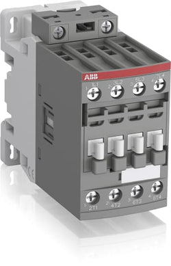
Ordering
1 piece
85364900
Popular Downloads
Dimensions
45 mm
101 mm
86 mm
0.36 kg
Technical
4
0
0
0
4P
IEC/EN 60947-1, IEC/EN 60947-4-1, UL 60335-2-40 LZGH2 A2L, UL 60947-1, UL 60947-4-1, CSA C22.2 No. 60335-2-40 LZGH2 A2L, CAN/CSA C22.2 No.60947-1, CAN/CSA C22.2 No.60947-4-1
Main Circuit 690 V
Control Circuit 50 / 60 Hz
Main Circuit 50 / 60 Hz
Control Circuit 50 / 60 Hz
Main Circuit 50 / 60 Hz
acc. to IEC 60947-4-1, Open Contactors Θ = 40 °C 55 A
(690 V) 40 °C 45 A
(690 V) 60 °C 40 A
(690 V) 70 °C 32 A
(690 V) 40 °C 45 A
(690 V) 60 °C 40 A
(690 V) 70 °C 32 A
(415 V) 60 °C 21.2 A
(440 V) 60 °C 20 A
(500 V) 60 °C 17.6 A
(690 V) 60 °C 10.5 A
(380 / 400 V) 60 °C 22 A
(220 / 230 / 240 V) 60 °C 23.2 A
(415 V) 60 °C 21.2 A
(440 V) 60 °C 20 A
(500 V) 60 °C 17.6 A
(690 V) 60 °C 10.5 A
(380 / 400 V) 60 °C 22 A
(220 / 230 / 240 V) 60 °C 23.2 A
(110 V) 2 Poles in Series, 40 °C 45 A
(110 V) 2 Poles in Series, 60 °C 40 A
(110 V) 2 Poles in Series, 70 °C 32 A
(110 V) 3 Poles in Series, 40 °C 45 A
(110 V) 3 Poles in Series, 60 °C 40 A
(110 V) 3 Poles in Series, 70 °C 32 A
(110 V) 4 Poles in Series, 40 °C 45 A
(110 V) 4 Poles in Series, 60 °C 40 A
(110 V) 4 Poles in Series, 70 °C 32 A
(220 V) 3 Poles in Series, 40 °C 45 A
(220 V) 3 Poles in Series, 60 °C 40 A
(220 V) 3 Poles in Series, 70 °C 32 A
(220 V) 4 Poles in Series, 40 °C 45 A
(220 V) 4 Poles in Series, 60 °C 40 A
(220 V) 4 Poles in Series, 70 °C 32 A
(72 V) 1-Pole, 40 °C 45 A
(72 V) 1-Pole, 60 °C 40 A
(72 V) 1-Pole, 70 °C 32 A
(72 V) 2 Poles in Series, 40 °C 45 A
(72 V) 2 Poles in Series, 60 °C 40 A
(72 V) 2 Poles in Series, 70 °C 32 A
(72 V) 3 Poles in Series, 40 °C 45 A
(72 V) 3 Poles in Series, 60 °C 40 A
(72 V) 3 Poles in Series, 70 °C 32 A
(72 V) 4 Poles in Series, 40 °C 45 A
(72 V) 4 Poles in Series, 60 °C 40 A
(72 V) 4 Poles in Series, 70 °C 32 A
(110 V) 2 Poles in Series, 40 °C 45 A
(110 V) 2 Poles in Series, 60 °C 40 A
(110 V) 2 Poles in Series, 70 °C 32 A
(110 V) 3 Poles in Series, 40 °C 45 A
(110 V) 3 Poles in Series, 60 °C 40 A
(110 V) 3 Poles in Series, 70 °C 32 A
(110 V) 4 Poles in Series, 40 °C 45 A
(110 V) 4 Poles in Series, 60 °C 40 A
(110 V) 4 Poles in Series, 70 °C 32 A
(220 V) 3 Poles in Series, 40 °C 45 A
(400 V) 11 kW
(415 V) 11 kW
(440 V) 11 kW
(500 V) 11 kW
(690 V) 9 kW
(220 / 230 / 240 V) 5.5 kW
(400 V) 11 kW
(415 V) 11 kW
(440 V) 11 kW
(500 V) 11 kW
(690 V) 9 kW
(220 / 230 / 240 V) 5.5 kW
at 40 °C Ambient Temp, in Free Air, from a Cold State 10 s 300 A
at 40 °C Ambient Temp, in Free Air, from a Cold State 15 min 55 A
at 40 °C Ambient Temp, in Free Air, from a Cold State 1 min 150 A
at 40 °C Ambient Temp, in Free Air, from a Cold State 1 s 450 A
at 40 °C Ambient Temp, in Free Air, from a Cold State 30 s 225 A
at 40 °C Ambient Temp, in Free Air, from a Cold State 10 s 300 A
at 40 °C Ambient Temp, in Free Air, from a Cold State 15 min 55 A
at 40 °C Ambient Temp, in Free Air, from a Cold State 1 min 150 A
at 40 °C Ambient Temp, in Free Air, from a Cold State 1 s 450 A
at 40 °C Ambient Temp, in Free Air, from a Cold State 30 s 225 A
acc. to IEC 60947-4-1 690 V
acc. to UL/CSA 600 V
acc. to IEC 60947-4-1 690 V
acc. to UL/CSA 600 V
6 kV
(AC-1) 600 cycles per hour
3600 cycles per hour
50 Hz 24 ... 60 V
60 Hz 24 ... 60 V
DC Operation 20 ... 60 V
50 Hz 24 ... 60 V
60 Hz 24 ... 60 V
DC Operation 20 ... 60 V
at Rated Operating Conditions AC-1 per Pole 1.6 W
at Rated Operating Conditions AC-3 per Pole 0.42 W
at Rated Operating Conditions AC-1 per Pole 1.6 W
at Rated Operating Conditions AC-3 per Pole 0.42 W
Between Coil De-energization and NC Contact Closing 13 ... 98 ms
Between Coil De-energization and NO Contact Opening 11 ... 95 ms
Between Coil Energization and NC Contact Opening 38 ... 90 ms
Between Coil Energization and NO Contact Closing 40 ... 95 ms
Between Coil De-energization and NC Contact Closing 13 ... 98 ms
Between Coil De-energization and NO Contact Opening 11 ... 95 ms
Between Coil Energization and NC Contact Opening 38 ... 90 ms
Between Coil Energization and NO Contact Closing 40 ... 95 ms
TH35-15 (35 x 15 mm Mounting Rail) acc. to IEC 60715
TH35-7.5 (35 x 7.5 mm Mounting Rail) acc. to IEC 60715
TH35-15 (35 x 15 mm Mounting Rail) acc. to IEC 60715
TH35-7.5 (35 x 7.5 mm Mounting Rail) acc. to IEC 60715
2 x M4 Screws Placed Diagonally
Flexible with Ferrule 1/2x 1.5 ... 16 mm²
Flexible with Insulated Ferrule 1/2x 1.5 ... 16 mm²
Rigid Solid 1/2x 1.5 ... 4 mm²
Rigid Stranded 1/2x 1.5 ... 16 mm²
Flexible with Ferrule 1/2x 1.5 ... 16 mm²
Flexible with Insulated Ferrule 1/2x 1.5 ... 16 mm²
Rigid Solid 1/2x 1.5 ... 4 mm²
Rigid Stranded 1/2x 1.5 ... 16 mm²
Flexible with Ferrule 1/2x 0.75 ... 2.5 mm²
Flexible with Insulated Ferrule 1x 0.75 ... 2.5 mm²
Flexible with Insulated Ferrule 2x 0.75 ... 1.5 mm²
Rigid Solid 1/2x 1 ... 2.5 mm²
Rigid Stranded 1/2x 1 ... 2.5 mm²
Flexible with Ferrule 1/2x 0.75 ... 2.5 mm²
Flexible with Insulated Ferrule 1x 0.75 ... 2.5 mm²
Flexible with Insulated Ferrule 2x 0.75 ... 1.5 mm²
Rigid Solid 1/2x 1 ... 2.5 mm²
Rigid Stranded 1/2x 1 ... 2.5 mm²
Control Circuit 10 mm
Main Circuit 12 mm
Control Circuit 10 mm
Main Circuit 12 mm
acc. to IEC 60529, IEC 60947-1, EN 60529 Coil Terminals IP20
acc. to IEC 60529, IEC 60947-1, EN 60529 Main Terminals IP20
acc. to IEC 60529, IEC 60947-1, EN 60529 Coil Terminals IP20
acc. to IEC 60529, IEC 60947-1, EN 60529 Main Terminals IP20
Control Circuit 1.2 N·m
Main Circuit 2.5 N·m
Control Circuit 1.2 N·m
Main Circuit 2.5 N·m
Screw Terminals
Block Contactor
Technical UL/CSA
Main Circuit 600 V
(600 V AC) 45 A
Rigid Solid 1/2x 16-10 AWG
Rigid Stranded 1/2x 16-6 AWG
Rigid Solid 1/2x 16-10 AWG
Rigid Stranded 1/2x 16-6 AWG
Rigid Solid 1/2x 18-14 AWG
Rigid Stranded 1/2x 18-14 AWG
Rigid Solid 1/2x 18-14 AWG
Rigid Stranded 1/2x 18-14 AWG
Control Circuit 11 in·lb
Main Circuit 22 in·lb
Control Circuit 11 in·lb
Main Circuit 22 in·lb
Environmental
Close to Contactor for Storage -60 ... +80 °C
Near Contactor for Operation in Free Air -40 ... 70 °C
Close to Contactor for Storage -60 ... +80 °C
Near Contactor for Operation in Free Air -40 ... 70 °C
Category B according to IEC 60947-1 Annex Q
Without Derating 3000 m
Closed, Shock Direction: B1 25 g
Open, Shock Direction: B1 5 g
Shock Direction: A 30 g
Shock Direction: B2 15 g
Shock Direction: C1 25 g
Shock Direction: C2 25 g
Closed, Shock Direction: B1 25 g
Open, Shock Direction: B1 5 g
Shock Direction: A 30 g
Shock Direction: B2 15 g
Shock Direction: C1 25 g
Shock Direction: C2 25 g
4g Closed Position & 2g Open position 5 ... 300 Hz
3
Material Compliance
Following EU Directive 2011/65/EU and Amendment 2015/863 July 22, 2019
Business To Business
5. Small Equipment (No External Dimension More Than 50 cm)
ABB EcoSolutions
Recycled Cardboard - 86 %
Recycled Metal - 28 %
Certificates and Declarations
Container Information
box 1 piece
87 mm
103 mm
47 mm
0.36 kg
3471523115217
box 18 piece
250 mm
300 mm
315 mm
12.96 kg
External Classifications and Standards
Q
EC000066 - Power contactor, AC switching
EC000066 - Power contactor, AC switching
EC000066 - Power contactor, AC switching
V11.0 : 27371003
39121529
4758 >> Iec Contactors
3705828
3211509

Ordering
1 piece
85364900
Popular Downloads
Dimensions
45 mm
101 mm
86 mm
0.36 kg
Technical
4
0
0
0
4P
IEC/EN 60947-1, IEC/EN 60947-4-1, UL 60335-2-40 LZGH2 A2L, UL 60947-1, UL 60947-4-1, CSA C22.2 No. 60335-2-40 LZGH2 A2L, CAN/CSA C22.2 No.60947-1, CAN/CSA C22.2 No.60947-4-1
Main Circuit 690 V
Control Circuit 50 / 60 Hz
Main Circuit 50 / 60 Hz
Control Circuit 50 / 60 Hz
Main Circuit 50 / 60 Hz
acc. to IEC 60947-4-1, Open Contactors Θ = 40 °C 55 A
(690 V) 40 °C 45 A
(690 V) 60 °C 40 A
(690 V) 70 °C 32 A
(690 V) 40 °C 45 A
(690 V) 60 °C 40 A
(690 V) 70 °C 32 A
(415 V) 60 °C 21.2 A
(440 V) 60 °C 20 A
(500 V) 60 °C 17.6 A
(690 V) 60 °C 10.5 A
(380 / 400 V) 60 °C 22 A
(220 / 230 / 240 V) 60 °C 23.2 A
(415 V) 60 °C 21.2 A
(440 V) 60 °C 20 A
(500 V) 60 °C 17.6 A
(690 V) 60 °C 10.5 A
(380 / 400 V) 60 °C 22 A
(220 / 230 / 240 V) 60 °C 23.2 A
(110 V) 2 Poles in Series, 40 °C 45 A
(110 V) 2 Poles in Series, 60 °C 40 A
(110 V) 2 Poles in Series, 70 °C 32 A
(110 V) 3 Poles in Series, 40 °C 45 A
(110 V) 3 Poles in Series, 60 °C 40 A
(110 V) 3 Poles in Series, 70 °C 32 A
(110 V) 4 Poles in Series, 40 °C 45 A
(110 V) 4 Poles in Series, 60 °C 40 A
(110 V) 4 Poles in Series, 70 °C 32 A
(220 V) 3 Poles in Series, 40 °C 45 A
(220 V) 3 Poles in Series, 60 °C 40 A
(220 V) 3 Poles in Series, 70 °C 32 A
(220 V) 4 Poles in Series, 40 °C 45 A
(220 V) 4 Poles in Series, 60 °C 40 A
(220 V) 4 Poles in Series, 70 °C 32 A
(72 V) 1-Pole, 40 °C 45 A
(72 V) 1-Pole, 60 °C 40 A
(72 V) 1-Pole, 70 °C 32 A
(72 V) 2 Poles in Series, 40 °C 45 A
(72 V) 2 Poles in Series, 60 °C 40 A
(72 V) 2 Poles in Series, 70 °C 32 A
(72 V) 3 Poles in Series, 40 °C 45 A
(72 V) 3 Poles in Series, 60 °C 40 A
(72 V) 3 Poles in Series, 70 °C 32 A
(72 V) 4 Poles in Series, 40 °C 45 A
(72 V) 4 Poles in Series, 60 °C 40 A
(72 V) 4 Poles in Series, 70 °C 32 A
(110 V) 2 Poles in Series, 40 °C 45 A
(110 V) 2 Poles in Series, 60 °C 40 A
(110 V) 2 Poles in Series, 70 °C 32 A
(110 V) 3 Poles in Series, 40 °C 45 A
(110 V) 3 Poles in Series, 60 °C 40 A
(110 V) 3 Poles in Series, 70 °C 32 A
(110 V) 4 Poles in Series, 40 °C 45 A
(110 V) 4 Poles in Series, 60 °C 40 A
(110 V) 4 Poles in Series, 70 °C 32 A
(220 V) 3 Poles in Series, 40 °C 45 A
(400 V) 11 kW
(415 V) 11 kW
(440 V) 11 kW
(500 V) 11 kW
(690 V) 9 kW
(220 / 230 / 240 V) 5.5 kW
(400 V) 11 kW
(415 V) 11 kW
(440 V) 11 kW
(500 V) 11 kW
(690 V) 9 kW
(220 / 230 / 240 V) 5.5 kW
at 40 °C Ambient Temp, in Free Air, from a Cold State 10 s 300 A
at 40 °C Ambient Temp, in Free Air, from a Cold State 15 min 55 A
at 40 °C Ambient Temp, in Free Air, from a Cold State 1 min 150 A
at 40 °C Ambient Temp, in Free Air, from a Cold State 1 s 450 A
at 40 °C Ambient Temp, in Free Air, from a Cold State 30 s 225 A
at 40 °C Ambient Temp, in Free Air, from a Cold State 10 s 300 A
at 40 °C Ambient Temp, in Free Air, from a Cold State 15 min 55 A
at 40 °C Ambient Temp, in Free Air, from a Cold State 1 min 150 A
at 40 °C Ambient Temp, in Free Air, from a Cold State 1 s 450 A
at 40 °C Ambient Temp, in Free Air, from a Cold State 30 s 225 A
acc. to IEC 60947-4-1 690 V
acc. to UL/CSA 600 V
acc. to IEC 60947-4-1 690 V
acc. to UL/CSA 600 V
6 kV
(AC-1) 600 cycles per hour
3600 cycles per hour
50 Hz 48 ... 130 V
60 Hz 48 ... 130 V
DC Operation 48 ... 130 V
50 Hz 48 ... 130 V
60 Hz 48 ... 130 V
DC Operation 48 ... 130 V
at Rated Operating Conditions AC-1 per Pole 1.6 W
at Rated Operating Conditions AC-3 per Pole 0.42 W
at Rated Operating Conditions AC-1 per Pole 1.6 W
at Rated Operating Conditions AC-3 per Pole 0.42 W
Between Coil De-energization and NC Contact Closing 13 ... 98 ms
Between Coil De-energization and NO Contact Opening 11 ... 95 ms
Between Coil Energization and NC Contact Opening 38 ... 90 ms
Between Coil Energization and NO Contact Closing 40 ... 95 ms
Between Coil De-energization and NC Contact Closing 13 ... 98 ms
Between Coil De-energization and NO Contact Opening 11 ... 95 ms
Between Coil Energization and NC Contact Opening 38 ... 90 ms
Between Coil Energization and NO Contact Closing 40 ... 95 ms
TH35-15 (35 x 15 mm Mounting Rail) acc. to IEC 60715
TH35-7.5 (35 x 7.5 mm Mounting Rail) acc. to IEC 60715
TH35-15 (35 x 15 mm Mounting Rail) acc. to IEC 60715
TH35-7.5 (35 x 7.5 mm Mounting Rail) acc. to IEC 60715
2 x M4 Screws Placed Diagonally
Flexible with Ferrule 1/2x 1.5 ... 16 mm²
Flexible with Insulated Ferrule 1/2x 1.5 ... 16 mm²
Rigid Solid 1/2x 1.5 ... 4 mm²
Rigid Stranded 1/2x 1.5 ... 16 mm²
Flexible with Ferrule 1/2x 1.5 ... 16 mm²
Flexible with Insulated Ferrule 1/2x 1.5 ... 16 mm²
Rigid Solid 1/2x 1.5 ... 4 mm²
Rigid Stranded 1/2x 1.5 ... 16 mm²
Flexible with Ferrule 1/2x 0.75 ... 2.5 mm²
Flexible with Insulated Ferrule 1x 0.75 ... 2.5 mm²
Flexible with Insulated Ferrule 2x 0.75 ... 1.5 mm²
Rigid Solid 1/2x 1 ... 2.5 mm²
Rigid Stranded 1/2x 1 ... 2.5 mm²
Flexible with Ferrule 1/2x 0.75 ... 2.5 mm²
Flexible with Insulated Ferrule 1x 0.75 ... 2.5 mm²
Flexible with Insulated Ferrule 2x 0.75 ... 1.5 mm²
Rigid Solid 1/2x 1 ... 2.5 mm²
Rigid Stranded 1/2x 1 ... 2.5 mm²
Control Circuit 10 mm
Main Circuit 12 mm
Control Circuit 10 mm
Main Circuit 12 mm
acc. to IEC 60529, IEC 60947-1, EN 60529 Coil Terminals IP20
acc. to IEC 60529, IEC 60947-1, EN 60529 Main Terminals IP20
acc. to IEC 60529, IEC 60947-1, EN 60529 Coil Terminals IP20
acc. to IEC 60529, IEC 60947-1, EN 60529 Main Terminals IP20
Control Circuit 1.2 N·m
Main Circuit 2.5 N·m
Control Circuit 1.2 N·m
Main Circuit 2.5 N·m
Screw Terminals
Block Contactor
Technical UL/CSA
Main Circuit 600 V
(600 V AC) 45 A
Rigid Solid 1/2x 16-10 AWG
Rigid Stranded 1/2x 16-6 AWG
Rigid Solid 1/2x 16-10 AWG
Rigid Stranded 1/2x 16-6 AWG
Rigid Solid 1/2x 18-14 AWG
Rigid Stranded 1/2x 18-14 AWG
Rigid Solid 1/2x 18-14 AWG
Rigid Stranded 1/2x 18-14 AWG
Control Circuit 11 in·lb
Main Circuit 22 in·lb
Control Circuit 11 in·lb
Main Circuit 22 in·lb
Environmental
Close to Contactor for Storage -60 ... +80 °C
Near Contactor for Operation in Free Air -40 ... 70 °C
Close to Contactor for Storage -60 ... +80 °C
Near Contactor for Operation in Free Air -40 ... 70 °C
Category B according to IEC 60947-1 Annex Q
Without Derating 3000 m
Closed, Shock Direction: B1 25 g
Open, Shock Direction: B1 5 g
Shock Direction: A 30 g
Shock Direction: B2 15 g
Shock Direction: C1 25 g
Shock Direction: C2 25 g
Closed, Shock Direction: B1 25 g
Open, Shock Direction: B1 5 g
Shock Direction: A 30 g
Shock Direction: B2 15 g
Shock Direction: C1 25 g
Shock Direction: C2 25 g
4g Closed Position & 2g Open position 5 ... 300 Hz
3
Material Compliance
Following EU Directive 2011/65/EU and Amendment 2015/863 July 22, 2019
Business To Business
5. Small Equipment (No External Dimension More Than 50 cm)
ABB EcoSolutions
Recycled Cardboard - 86 %
Recycled Metal - 28 %
Certificates and Declarations
Container Information
box 1 piece
87 mm
103 mm
47 mm
0.36 kg
3471523115224
box 18 piece
250 mm
300 mm
315 mm
12.96 kg
External Classifications and Standards
Q
EC000066 - Power contactor, AC switching
EC000066 - Power contactor, AC switching
EC000066 - Power contactor, AC switching
V11.0 : 27371003
39121529
4758 >> Iec Contactors
3705829
3211510

Ordering
1 piece
85364900
Popular Downloads
Dimensions
45 mm
101 mm
86 mm
0.36 kg
Technical
4
0
0
0
4P
IEC/EN 60947-1, IEC/EN 60947-4-1, UL 60335-2-40 LZGH2 A2L, UL 60947-1, UL 60947-4-1, CSA C22.2 No. 60335-2-40 LZGH2 A2L, CAN/CSA C22.2 No.60947-1, CAN/CSA C22.2 No.60947-4-1
Main Circuit 690 V
Control Circuit 50 / 60 Hz
Main Circuit 50 / 60 Hz
Control Circuit 50 / 60 Hz
Main Circuit 50 / 60 Hz
acc. to IEC 60947-4-1, Open Contactors Θ = 40 °C 55 A
(690 V) 40 °C 45 A
(690 V) 60 °C 40 A
(690 V) 70 °C 32 A
(690 V) 40 °C 45 A
(690 V) 60 °C 40 A
(690 V) 70 °C 32 A
(415 V) 60 °C 21.2 A
(440 V) 60 °C 20 A
(500 V) 60 °C 17.6 A
(690 V) 60 °C 10.5 A
(380 / 400 V) 60 °C 22 A
(220 / 230 / 240 V) 60 °C 23.2 A
(415 V) 60 °C 21.2 A
(440 V) 60 °C 20 A
(500 V) 60 °C 17.6 A
(690 V) 60 °C 10.5 A
(380 / 400 V) 60 °C 22 A
(220 / 230 / 240 V) 60 °C 23.2 A
(110 V) 2 Poles in Series, 40 °C 45 A
(110 V) 2 Poles in Series, 60 °C 40 A
(110 V) 2 Poles in Series, 70 °C 32 A
(110 V) 3 Poles in Series, 40 °C 45 A
(110 V) 3 Poles in Series, 60 °C 40 A
(110 V) 3 Poles in Series, 70 °C 32 A
(110 V) 4 Poles in Series, 40 °C 45 A
(110 V) 4 Poles in Series, 60 °C 40 A
(110 V) 4 Poles in Series, 70 °C 32 A
(220 V) 3 Poles in Series, 40 °C 45 A
(220 V) 3 Poles in Series, 60 °C 40 A
(220 V) 3 Poles in Series, 70 °C 32 A
(220 V) 4 Poles in Series, 40 °C 45 A
(220 V) 4 Poles in Series, 60 °C 40 A
(220 V) 4 Poles in Series, 70 °C 32 A
(72 V) 1-Pole, 40 °C 45 A
(72 V) 1-Pole, 60 °C 40 A
(72 V) 1-Pole, 70 °C 32 A
(72 V) 2 Poles in Series, 40 °C 45 A
(72 V) 2 Poles in Series, 60 °C 40 A
(72 V) 2 Poles in Series, 70 °C 32 A
(72 V) 3 Poles in Series, 40 °C 45 A
(72 V) 3 Poles in Series, 60 °C 40 A
(72 V) 3 Poles in Series, 70 °C 32 A
(72 V) 4 Poles in Series, 40 °C 45 A
(72 V) 4 Poles in Series, 60 °C 40 A
(72 V) 4 Poles in Series, 70 °C 32 A
(110 V) 2 Poles in Series, 40 °C 45 A
(110 V) 2 Poles in Series, 60 °C 40 A
(110 V) 2 Poles in Series, 70 °C 32 A
(110 V) 3 Poles in Series, 40 °C 45 A
(110 V) 3 Poles in Series, 60 °C 40 A
(110 V) 3 Poles in Series, 70 °C 32 A
(110 V) 4 Poles in Series, 40 °C 45 A
(110 V) 4 Poles in Series, 60 °C 40 A
(110 V) 4 Poles in Series, 70 °C 32 A
(220 V) 3 Poles in Series, 40 °C 45 A
(400 V) 11 kW
(415 V) 11 kW
(440 V) 11 kW
(500 V) 11 kW
(690 V) 9 kW
(220 / 230 / 240 V) 5.5 kW
(400 V) 11 kW
(415 V) 11 kW
(440 V) 11 kW
(500 V) 11 kW
(690 V) 9 kW
(220 / 230 / 240 V) 5.5 kW
at 40 °C Ambient Temp, in Free Air, from a Cold State 10 s 300 A
at 40 °C Ambient Temp, in Free Air, from a Cold State 15 min 55 A
at 40 °C Ambient Temp, in Free Air, from a Cold State 1 min 150 A
at 40 °C Ambient Temp, in Free Air, from a Cold State 1 s 450 A
at 40 °C Ambient Temp, in Free Air, from a Cold State 30 s 225 A
at 40 °C Ambient Temp, in Free Air, from a Cold State 10 s 300 A
at 40 °C Ambient Temp, in Free Air, from a Cold State 15 min 55 A
at 40 °C Ambient Temp, in Free Air, from a Cold State 1 min 150 A
at 40 °C Ambient Temp, in Free Air, from a Cold State 1 s 450 A
at 40 °C Ambient Temp, in Free Air, from a Cold State 30 s 225 A
acc. to IEC 60947-4-1 690 V
acc. to UL/CSA 600 V
acc. to IEC 60947-4-1 690 V
acc. to UL/CSA 600 V
6 kV
(AC-1) 600 cycles per hour
3600 cycles per hour
50 Hz 100 ... 250 V
60 Hz 100 ... 250 V
DC Operation 100 ... 250 V
50 Hz 100 ... 250 V
60 Hz 100 ... 250 V
DC Operation 100 ... 250 V
at Rated Operating Conditions AC-1 per Pole 1.6 W
at Rated Operating Conditions AC-3 per Pole 0.42 W
at Rated Operating Conditions AC-1 per Pole 1.6 W
at Rated Operating Conditions AC-3 per Pole 0.42 W
Between Coil De-energization and NC Contact Closing 13 ... 98 ms
Between Coil De-energization and NO Contact Opening 11 ... 95 ms
Between Coil Energization and NC Contact Opening 38 ... 90 ms
Between Coil Energization and NO Contact Closing 40 ... 95 ms
Between Coil De-energization and NC Contact Closing 13 ... 98 ms
Between Coil De-energization and NO Contact Opening 11 ... 95 ms
Between Coil Energization and NC Contact Opening 38 ... 90 ms
Between Coil Energization and NO Contact Closing 40 ... 95 ms
TH35-15 (35 x 15 mm Mounting Rail) acc. to IEC 60715
TH35-7.5 (35 x 7.5 mm Mounting Rail) acc. to IEC 60715
TH35-15 (35 x 15 mm Mounting Rail) acc. to IEC 60715
TH35-7.5 (35 x 7.5 mm Mounting Rail) acc. to IEC 60715
2 x M4 Screws Placed Diagonally
Flexible with Ferrule 1/2x 1.5 ... 16 mm²
Flexible with Insulated Ferrule 1/2x 1.5 ... 16 mm²
Rigid Solid 1/2x 1.5 ... 4 mm²
Rigid Stranded 1/2x 1.5 ... 16 mm²
Flexible with Ferrule 1/2x 1.5 ... 16 mm²
Flexible with Insulated Ferrule 1/2x 1.5 ... 16 mm²
Rigid Solid 1/2x 1.5 ... 4 mm²
Rigid Stranded 1/2x 1.5 ... 16 mm²
Flexible with Ferrule 1/2x 0.75 ... 2.5 mm²
Flexible with Insulated Ferrule 1x 0.75 ... 2.5 mm²
Flexible with Insulated Ferrule 2x 0.75 ... 1.5 mm²
Rigid Solid 1/2x 1 ... 2.5 mm²
Rigid Stranded 1/2x 1 ... 2.5 mm²
Flexible with Ferrule 1/2x 0.75 ... 2.5 mm²
Flexible with Insulated Ferrule 1x 0.75 ... 2.5 mm²
Flexible with Insulated Ferrule 2x 0.75 ... 1.5 mm²
Rigid Solid 1/2x 1 ... 2.5 mm²
Rigid Stranded 1/2x 1 ... 2.5 mm²
Control Circuit 10 mm
Main Circuit 12 mm
Control Circuit 10 mm
Main Circuit 12 mm
acc. to IEC 60529, IEC 60947-1, EN 60529 Coil Terminals IP20
acc. to IEC 60529, IEC 60947-1, EN 60529 Main Terminals IP20
acc. to IEC 60529, IEC 60947-1, EN 60529 Coil Terminals IP20
acc. to IEC 60529, IEC 60947-1, EN 60529 Main Terminals IP20
Control Circuit 1.2 N·m
Main Circuit 2.5 N·m
Control Circuit 1.2 N·m
Main Circuit 2.5 N·m
Screw Terminals
Block Contactor
Technical UL/CSA
Main Circuit 600 V
(600 V AC) 45 A
Rigid Solid 1/2x 16-10 AWG
Rigid Stranded 1/2x 16-6 AWG
Rigid Solid 1/2x 16-10 AWG
Rigid Stranded 1/2x 16-6 AWG
Rigid Solid 1/2x 18-14 AWG
Rigid Stranded 1/2x 18-14 AWG
Rigid Solid 1/2x 18-14 AWG
Rigid Stranded 1/2x 18-14 AWG
Control Circuit 11 in·lb
Main Circuit 22 in·lb
Control Circuit 11 in·lb
Main Circuit 22 in·lb
Environmental
Close to Contactor for Storage -60 ... +80 °C
Near Contactor for Operation in Free Air -40 ... 70 °C
Close to Contactor for Storage -60 ... +80 °C
Near Contactor for Operation in Free Air -40 ... 70 °C
Category B according to IEC 60947-1 Annex Q
Without Derating 3000 m
Closed, Shock Direction: B1 25 g
Open, Shock Direction: B1 5 g
Shock Direction: A 30 g
Shock Direction: B2 15 g
Shock Direction: C1 25 g
Shock Direction: C2 25 g
Closed, Shock Direction: B1 25 g
Open, Shock Direction: B1 5 g
Shock Direction: A 30 g
Shock Direction: B2 15 g
Shock Direction: C1 25 g
Shock Direction: C2 25 g
4g Closed Position & 2g Open position 5 ... 300 Hz
3
Material Compliance
Following EU Directive 2011/65/EU and Amendment 2015/863 July 22, 2019
Business To Business
5. Small Equipment (No External Dimension More Than 50 cm)
ABB EcoSolutions
Recycled Cardboard - 86 %
Recycled Metal - 28 %
Certificates and Declarations
Container Information
box 1 piece
87 mm
103 mm
47 mm
0.36 kg
3471523115231
box 18 piece
250 mm
300 mm
315 mm
12.96 kg
External Classifications and Standards
Q
EC000066 - Power contactor, AC switching
EC000066 - Power contactor, AC switching
EC000066 - Power contactor, AC switching
V11.0 : 27371003
39121529
4758 >> Iec Contactors
3705830
3211511

Ordering
1 piece
85364900
Popular Downloads
Dimensions
45 mm
101 mm
86 mm
0.4 kg
Technical
4
0
0
0
4P
IEC/EN 60947-1, IEC/EN 60947-4-1, UL 60335-2-40 LZGH2 A2L, UL 60947-1, UL 60947-4-1, CSA C22.2 No. 60335-2-40 LZGH2 A2L, CAN/CSA C22.2 No.60947-1, CAN/CSA C22.2 No.60947-4-1
Main Circuit 690 V
Control Circuit 50 / 60 Hz
Main Circuit 50 / 60 Hz
Control Circuit 50 / 60 Hz
Main Circuit 50 / 60 Hz
acc. to IEC 60947-4-1, Open Contactors Θ = 40 °C 55 A
(690 V) 40 °C 45 A
(690 V) 60 °C 40 A
(690 V) 70 °C 32 A
(690 V) 40 °C 45 A
(690 V) 60 °C 40 A
(690 V) 70 °C 32 A
(415 V) 60 °C 21.2 A
(440 V) 60 °C 20 A
(500 V) 60 °C 17.6 A
(690 V) 60 °C 10.5 A
(380 / 400 V) 60 °C 22 A
(220 / 230 / 240 V) 60 °C 23.2 A
(415 V) 60 °C 21.2 A
(440 V) 60 °C 20 A
(500 V) 60 °C 17.6 A
(690 V) 60 °C 10.5 A
(380 / 400 V) 60 °C 22 A
(220 / 230 / 240 V) 60 °C 23.2 A
(110 V) 2 Poles in Series, 40 °C 45 A
(110 V) 2 Poles in Series, 60 °C 40 A
(110 V) 2 Poles in Series, 70 °C 32 A
(110 V) 3 Poles in Series, 40 °C 45 A
(110 V) 3 Poles in Series, 60 °C 40 A
(110 V) 3 Poles in Series, 70 °C 32 A
(110 V) 4 Poles in Series, 40 °C 45 A
(110 V) 4 Poles in Series, 60 °C 40 A
(110 V) 4 Poles in Series, 70 °C 32 A
(220 V) 3 Poles in Series, 40 °C 45 A
(220 V) 3 Poles in Series, 60 °C 40 A
(220 V) 3 Poles in Series, 70 °C 32 A
(220 V) 4 Poles in Series, 40 °C 45 A
(220 V) 4 Poles in Series, 60 °C 40 A
(220 V) 4 Poles in Series, 70 °C 32 A
(72 V) 1-Pole, 40 °C 45 A
(72 V) 1-Pole, 60 °C 40 A
(72 V) 1-Pole, 70 °C 32 A
(72 V) 2 Poles in Series, 40 °C 45 A
(72 V) 2 Poles in Series, 60 °C 40 A
(72 V) 2 Poles in Series, 70 °C 32 A
(72 V) 3 Poles in Series, 40 °C 45 A
(72 V) 3 Poles in Series, 60 °C 40 A
(72 V) 3 Poles in Series, 70 °C 32 A
(72 V) 4 Poles in Series, 40 °C 45 A
(72 V) 4 Poles in Series, 60 °C 40 A
(72 V) 4 Poles in Series, 70 °C 32 A
(110 V) 2 Poles in Series, 40 °C 45 A
(110 V) 2 Poles in Series, 60 °C 40 A
(110 V) 2 Poles in Series, 70 °C 32 A
(110 V) 3 Poles in Series, 40 °C 45 A
(110 V) 3 Poles in Series, 60 °C 40 A
(110 V) 3 Poles in Series, 70 °C 32 A
(110 V) 4 Poles in Series, 40 °C 45 A
(110 V) 4 Poles in Series, 60 °C 40 A
(110 V) 4 Poles in Series, 70 °C 32 A
(220 V) 3 Poles in Series, 40 °C 45 A
(400 V) 11 kW
(415 V) 11 kW
(440 V) 11 kW
(500 V) 11 kW
(690 V) 9 kW
(220 / 230 / 240 V) 5.5 kW
(400 V) 11 kW
(415 V) 11 kW
(440 V) 11 kW
(500 V) 11 kW
(690 V) 9 kW
(220 / 230 / 240 V) 5.5 kW
at 40 °C Ambient Temp, in Free Air, from a Cold State 10 s 300 A
at 40 °C Ambient Temp, in Free Air, from a Cold State 15 min 55 A
at 40 °C Ambient Temp, in Free Air, from a Cold State 1 min 150 A
at 40 °C Ambient Temp, in Free Air, from a Cold State 1 s 450 A
at 40 °C Ambient Temp, in Free Air, from a Cold State 30 s 225 A
at 40 °C Ambient Temp, in Free Air, from a Cold State 10 s 300 A
at 40 °C Ambient Temp, in Free Air, from a Cold State 15 min 55 A
at 40 °C Ambient Temp, in Free Air, from a Cold State 1 min 150 A
at 40 °C Ambient Temp, in Free Air, from a Cold State 1 s 450 A
at 40 °C Ambient Temp, in Free Air, from a Cold State 30 s 225 A
acc. to IEC 60947-4-1 690 V
acc. to UL/CSA 600 V
acc. to IEC 60947-4-1 690 V
acc. to UL/CSA 600 V
6 kV
(AC-1) 600 cycles per hour
3600 cycles per hour
50 Hz 250 ... 500 V
60 Hz 250 ... 500 V
DC Operation 250 ... 500 V
50 Hz 250 ... 500 V
60 Hz 250 ... 500 V
DC Operation 250 ... 500 V
at Rated Operating Conditions AC-1 per Pole 1.6 W
at Rated Operating Conditions AC-3 per Pole 0.42 W
at Rated Operating Conditions AC-1 per Pole 1.6 W
at Rated Operating Conditions AC-3 per Pole 0.42 W
Between Coil De-energization and NC Contact Closing 13 ... 98 ms
Between Coil De-energization and NO Contact Opening 11 ... 95 ms
Between Coil Energization and NC Contact Opening 38 ... 90 ms
Between Coil Energization and NO Contact Closing 40 ... 95 ms
Between Coil De-energization and NC Contact Closing 13 ... 98 ms
Between Coil De-energization and NO Contact Opening 11 ... 95 ms
Between Coil Energization and NC Contact Opening 38 ... 90 ms
Between Coil Energization and NO Contact Closing 40 ... 95 ms
TH35-15 (35 x 15 mm Mounting Rail) acc. to IEC 60715
TH35-7.5 (35 x 7.5 mm Mounting Rail) acc. to IEC 60715
TH35-15 (35 x 15 mm Mounting Rail) acc. to IEC 60715
TH35-7.5 (35 x 7.5 mm Mounting Rail) acc. to IEC 60715
2 x M4 Screws Placed Diagonally
Flexible with Ferrule 1/2x 1.5 ... 16 mm²
Flexible with Insulated Ferrule 1/2x 1.5 ... 16 mm²
Rigid Solid 1/2x 1.5 ... 4 mm²
Rigid Stranded 1/2x 1.5 ... 16 mm²
Flexible with Ferrule 1/2x 1.5 ... 16 mm²
Flexible with Insulated Ferrule 1/2x 1.5 ... 16 mm²
Rigid Solid 1/2x 1.5 ... 4 mm²
Rigid Stranded 1/2x 1.5 ... 16 mm²
Flexible with Ferrule 1/2x 0.75 ... 2.5 mm²
Flexible with Insulated Ferrule 1x 0.75 ... 2.5 mm²
Flexible with Insulated Ferrule 2x 0.75 ... 1.5 mm²
Rigid Solid 1/2x 1 ... 2.5 mm²
Rigid Stranded 1/2x 1 ... 2.5 mm²
Flexible with Ferrule 1/2x 0.75 ... 2.5 mm²
Flexible with Insulated Ferrule 1x 0.75 ... 2.5 mm²
Flexible with Insulated Ferrule 2x 0.75 ... 1.5 mm²
Rigid Solid 1/2x 1 ... 2.5 mm²
Rigid Stranded 1/2x 1 ... 2.5 mm²
Control Circuit 10 mm
Main Circuit 12 mm
Control Circuit 10 mm
Main Circuit 12 mm
acc. to IEC 60529, IEC 60947-1, EN 60529 Coil Terminals IP20
acc. to IEC 60529, IEC 60947-1, EN 60529 Main Terminals IP20
acc. to IEC 60529, IEC 60947-1, EN 60529 Coil Terminals IP20
acc. to IEC 60529, IEC 60947-1, EN 60529 Main Terminals IP20
Control Circuit 1.2 N·m
Main Circuit 2.5 N·m
Control Circuit 1.2 N·m
Main Circuit 2.5 N·m
Screw Terminals
Block Contactor
Technical UL/CSA
Main Circuit 600 V
(600 V AC) 45 A
Rigid Solid 1/2x 16-10 AWG
Rigid Stranded 1/2x 16-6 AWG
Rigid Solid 1/2x 16-10 AWG
Rigid Stranded 1/2x 16-6 AWG
Rigid Solid 1/2x 18-14 AWG
Rigid Stranded 1/2x 18-14 AWG
Rigid Solid 1/2x 18-14 AWG
Rigid Stranded 1/2x 18-14 AWG
Control Circuit 11 in·lb
Main Circuit 22 in·lb
Control Circuit 11 in·lb
Main Circuit 22 in·lb
Environmental
Close to Contactor for Storage -60 ... +80 °C
Near Contactor for Operation in Free Air -40 ... 70 °C
Close to Contactor for Storage -60 ... +80 °C
Near Contactor for Operation in Free Air -40 ... 70 °C
Category B according to IEC 60947-1 Annex Q
Without Derating 3000 m
Closed, Shock Direction: B1 25 g
Open, Shock Direction: B1 5 g
Shock Direction: A 30 g
Shock Direction: B2 15 g
Shock Direction: C1 25 g
Shock Direction: C2 25 g
Closed, Shock Direction: B1 25 g
Open, Shock Direction: B1 5 g
Shock Direction: A 30 g
Shock Direction: B2 15 g
Shock Direction: C1 25 g
Shock Direction: C2 25 g
4g Closed Position & 2g Open position 5 ... 300 Hz
3
Material Compliance
Following EU Directive 2011/65/EU and Amendment 2015/863 July 22, 2019
Business To Business
5. Small Equipment (No External Dimension More Than 50 cm)
ABB EcoSolutions
Recycled Cardboard - 86 %
Recycled Metal - 28 %
Certificates and Declarations
Container Information
box 1 piece
87 mm
103 mm
47 mm
0.4 kg
3471523115248
box 18 piece
250 mm
300 mm
315 mm
14.4 kg
External Classifications and Standards
Q
EC000066 - Power contactor, AC switching
EC000066 - Power contactor, AC switching
EC000066 - Power contactor, AC switching
V11.0 : 27371003
39121529
4758 >> Iec Contactors
3705831
3211512

Ordering
1 piece
85364900
Popular Downloads
Dimensions
45 mm
101 mm
86 mm
0.36 kg
Technical
2
2
0
0
4P
IEC/EN 60947-1, IEC/EN 60947-4-1, UL 60335-2-40 LZGH2 A2L, UL 60947-1, UL 60947-4-1, CSA C22.2 No. 60335-2-40 LZGH2 A2L, CAN/CSA C22.2 No.60947-1, CAN/CSA C22.2 No.60947-4-1
Main Circuit 690 V
Control Circuit 50 / 60 Hz
Main Circuit 50 / 60 Hz
Control Circuit 50 / 60 Hz
Main Circuit 50 / 60 Hz
acc. to IEC 60947-4-1, Open Contactors Θ = 40 °C 55 A
(690 V) 40 °C 45 A
(690 V) 60 °C 40 A
(690 V) 70 °C 32 A
(690 V) 40 °C 45 A
(690 V) 60 °C 40 A
(690 V) 70 °C 32 A
(415 V) 60 °C 21.2 A
(440 V) 60 °C 20 A
(500 V) 60 °C 17.6 A
(690 V) 60 °C 10.5 A
(380 / 400 V) 60 °C 22 A
(220 / 230 / 240 V) 60 °C 23.2 A
(415 V) 60 °C 21.2 A
(440 V) 60 °C 20 A
(500 V) 60 °C 17.6 A
(690 V) 60 °C 10.5 A
(380 / 400 V) 60 °C 22 A
(220 / 230 / 240 V) 60 °C 23.2 A
(400 V) 11 kW
(415 V) 11 kW
(440 V) 11 kW
(500 V) 11 kW
(690 V) 9 kW
(220 / 230 / 240 V) 5.5 kW
(400 V) 11 kW
(415 V) 11 kW
(440 V) 11 kW
(500 V) 11 kW
(690 V) 9 kW
(220 / 230 / 240 V) 5.5 kW
at 40 °C Ambient Temp, in Free Air, from a Cold State 10 s 300 A
at 40 °C Ambient Temp, in Free Air, from a Cold State 15 min 55 A
at 40 °C Ambient Temp, in Free Air, from a Cold State 1 min 150 A
at 40 °C Ambient Temp, in Free Air, from a Cold State 1 s 450 A
at 40 °C Ambient Temp, in Free Air, from a Cold State 30 s 225 A
acc. to IEC 60947-4-1 690 V
acc. to UL/CSA 600 V
acc. to IEC 60947-4-1 690 V
acc. to UL/CSA 600 V
6 kV
(AC-1) 600 cycles per hour
3600 cycles per hour
50 Hz 24 ... 60 V
60 Hz 24 ... 60 V
DC Operation 20 ... 60 V
50 Hz 24 ... 60 V
60 Hz 24 ... 60 V
DC Operation 20 ... 60 V
at Rated Operating Conditions AC-1 per Pole 1.6 W
at Rated Operating Conditions AC-3 per Pole 0.42 W
at Rated Operating Conditions AC-1 per Pole 1.6 W
at Rated Operating Conditions AC-3 per Pole 0.42 W
Between Coil De-energization and NC Contact Closing 13 ... 98 ms
Between Coil De-energization and NO Contact Opening 11 ... 95 ms
Between Coil Energization and NC Contact Opening 38 ... 90 ms
Between Coil Energization and NO Contact Closing 40 ... 95 ms
Between Coil De-energization and NC Contact Closing 13 ... 98 ms
Between Coil De-energization and NO Contact Opening 11 ... 95 ms
Between Coil Energization and NC Contact Opening 38 ... 90 ms
Between Coil Energization and NO Contact Closing 40 ... 95 ms
TH35-15 (35 x 15 mm Mounting Rail) acc. to IEC 60715
TH35-7.5 (35 x 7.5 mm Mounting Rail) acc. to IEC 60715
TH35-15 (35 x 15 mm Mounting Rail) acc. to IEC 60715
TH35-7.5 (35 x 7.5 mm Mounting Rail) acc. to IEC 60715
2 x M4 Screws Placed Diagonally
Flexible with Ferrule 1/2x 1.5 ... 16 mm²
Flexible with Insulated Ferrule 1/2x 1.5 ... 16 mm²
Rigid Solid 1/2x 1.5 ... 4 mm²
Rigid Stranded 1/2x 1.5 ... 16 mm²
Flexible with Ferrule 1/2x 1.5 ... 16 mm²
Flexible with Insulated Ferrule 1/2x 1.5 ... 16 mm²
Rigid Solid 1/2x 1.5 ... 4 mm²
Rigid Stranded 1/2x 1.5 ... 16 mm²
Flexible with Ferrule 1/2x 0.75 ... 2.5 mm²
Flexible with Insulated Ferrule 1x 0.75 ... 2.5 mm²
Flexible with Insulated Ferrule 2x 0.75 ... 1.5 mm²
Rigid Solid 1/2x 1 ... 2.5 mm²
Rigid Stranded 1/2x 1 ... 2.5 mm²
Flexible with Ferrule 1/2x 0.75 ... 2.5 mm²
Flexible with Insulated Ferrule 1x 0.75 ... 2.5 mm²
Flexible with Insulated Ferrule 2x 0.75 ... 1.5 mm²
Rigid Solid 1/2x 1 ... 2.5 mm²
Rigid Stranded 1/2x 1 ... 2.5 mm²
Control Circuit 10 mm
Main Circuit 12 mm
Control Circuit 10 mm
Main Circuit 12 mm
acc. to IEC 60529, IEC 60947-1, EN 60529 Coil Terminals IP20
acc. to IEC 60529, IEC 60947-1, EN 60529 Main Terminals IP20
acc. to IEC 60529, IEC 60947-1, EN 60529 Coil Terminals IP20
acc. to IEC 60529, IEC 60947-1, EN 60529 Main Terminals IP20
Control Circuit 1.2 N·m
Main Circuit 2.5 N·m
Control Circuit 1.2 N·m
Main Circuit 2.5 N·m
Screw Terminals
Block Contactor
Technical UL/CSA
Main Circuit 600 V
(600 V AC) 45 A
Rigid Solid 1/2x 16-10 AWG
Rigid Stranded 1/2x 16-6 AWG
Rigid Solid 1/2x 16-10 AWG
Rigid Stranded 1/2x 16-6 AWG
Rigid Solid 1/2x 18-14 AWG
Rigid Stranded 1/2x 18-14 AWG
Rigid Solid 1/2x 18-14 AWG
Rigid Stranded 1/2x 18-14 AWG
Control Circuit 11 in·lb
Main Circuit 22 in·lb
Control Circuit 11 in·lb
Main Circuit 22 in·lb
Environmental
Close to Contactor for Storage -60 ... +80 °C
Near Contactor for Operation in Free Air -40 ... 70 °C
Close to Contactor for Storage -60 ... +80 °C
Near Contactor for Operation in Free Air -40 ... 70 °C
Category B according to IEC 60947-1 Annex Q
Without Derating 3000 m
Closed, Shock Direction: A 30 g
Closed, Shock Direction: B1 25 g
Closed, Shock Direction: B2 15 g
Closed, Shock Direction: C1 25 g
Closed, Shock Direction: C2 25 g
Open, Shock Direction: A 25 g
Open, Shock Direction: B1 5 g
Open, Shock Direction: B2 10 g
Open, Shock Direction: C1 20 g
Open, Shock Direction: C2 20 g
4g Closed Position & 2g Open position 5 ... 300 Hz
3
Material Compliance
Following EU Directive 2011/65/EU and Amendment 2015/863 July 22, 2019
Business To Business
5. Small Equipment (No External Dimension More Than 50 cm)
ABB EcoSolutions
Recycled Cardboard - 86 %
Recycled Metal - 28 %
Certificates and Declarations
Container Information
box 1 piece
87 mm
103 mm
47 mm
0.36 kg
3471523116412
box 18 piece
250 mm
300 mm
315 mm
12.96 kg
External Classifications and Standards
Q
EC000066 - Power contactor, AC switching
EC000066 - Power contactor, AC switching
EC000066 - Power contactor, AC switching
V11.0 : 27371003
39121529
4758 >> Iec Contactors
3705844
3211513

Ordering
1 piece
85364900
Popular Downloads
Dimensions
45 mm
101 mm
86 mm
0.36 kg
Technical
2
2
0
0
4P
IEC/EN 60947-1, IEC/EN 60947-4-1, UL 60335-2-40 LZGH2 A2L, UL 60947-1, UL 60947-4-1, CSA C22.2 No. 60335-2-40 LZGH2 A2L, CAN/CSA C22.2 No.60947-1, CAN/CSA C22.2 No.60947-4-1
Main Circuit 690 V
Control Circuit 50 / 60 Hz
Main Circuit 50 / 60 Hz
Control Circuit 50 / 60 Hz
Main Circuit 50 / 60 Hz
acc. to IEC 60947-4-1, Open Contactors Θ = 40 °C 55 A
(690 V) 40 °C 45 A
(690 V) 60 °C 40 A
(690 V) 70 °C 32 A
(690 V) 40 °C 45 A
(690 V) 60 °C 40 A
(690 V) 70 °C 32 A
(415 V) 60 °C 21.2 A
(440 V) 60 °C 20 A
(500 V) 60 °C 17.6 A
(690 V) 60 °C 10.5 A
(380 / 400 V) 60 °C 22 A
(220 / 230 / 240 V) 60 °C 23.2 A
(415 V) 60 °C 21.2 A
(440 V) 60 °C 20 A
(500 V) 60 °C 17.6 A
(690 V) 60 °C 10.5 A
(380 / 400 V) 60 °C 22 A
(220 / 230 / 240 V) 60 °C 23.2 A
(400 V) 11 kW
(415 V) 11 kW
(440 V) 11 kW
(500 V) 11 kW
(690 V) 9 kW
(220 / 230 / 240 V) 5.5 kW
(400 V) 11 kW
(415 V) 11 kW
(440 V) 11 kW
(500 V) 11 kW
(690 V) 9 kW
(220 / 230 / 240 V) 5.5 kW
at 40 °C Ambient Temp, in Free Air, from a Cold State 10 s 300 A
at 40 °C Ambient Temp, in Free Air, from a Cold State 15 min 55 A
at 40 °C Ambient Temp, in Free Air, from a Cold State 1 min 150 A
at 40 °C Ambient Temp, in Free Air, from a Cold State 1 s 450 A
at 40 °C Ambient Temp, in Free Air, from a Cold State 30 s 225 A
at 40 °C Ambient Temp, in Free Air, from a Cold State 10 s 300 A
at 40 °C Ambient Temp, in Free Air, from a Cold State 15 min 55 A
at 40 °C Ambient Temp, in Free Air, from a Cold State 1 min 150 A
at 40 °C Ambient Temp, in Free Air, from a Cold State 1 s 450 A
at 40 °C Ambient Temp, in Free Air, from a Cold State 30 s 225 A
acc. to IEC 60947-4-1 690 V
acc. to UL/CSA 600 V
acc. to IEC 60947-4-1 690 V
acc. to UL/CSA 600 V
6 kV
(AC-1) 600 cycles per hour
3600 cycles per hour
50 Hz 48 ... 130 V
60 Hz 48 ... 130 V
DC Operation 48 ... 130 V
50 Hz 48 ... 130 V
60 Hz 48 ... 130 V
DC Operation 48 ... 130 V
at Rated Operating Conditions AC-1 per Pole 1.6 W
at Rated Operating Conditions AC-3 per Pole 0.42 W
at Rated Operating Conditions AC-1 per Pole 1.6 W
at Rated Operating Conditions AC-3 per Pole 0.42 W
Between Coil De-energization and NC Contact Closing 13 ... 98 ms
Between Coil De-energization and NO Contact Opening 11 ... 95 ms
Between Coil Energization and NC Contact Opening 38 ... 90 ms
Between Coil Energization and NO Contact Closing 40 ... 95 ms
Between Coil De-energization and NC Contact Closing 13 ... 98 ms
Between Coil De-energization and NO Contact Opening 11 ... 95 ms
Between Coil Energization and NC Contact Opening 38 ... 90 ms
Between Coil Energization and NO Contact Closing 40 ... 95 ms
TH35-15 (35 x 15 mm Mounting Rail) acc. to IEC 60715
TH35-7.5 (35 x 7.5 mm Mounting Rail) acc. to IEC 60715
TH35-15 (35 x 15 mm Mounting Rail) acc. to IEC 60715
TH35-7.5 (35 x 7.5 mm Mounting Rail) acc. to IEC 60715
2 x M4 Screws Placed Diagonally
Flexible with Ferrule 1/2x 1.5 ... 16 mm²
Flexible with Insulated Ferrule 1/2x 1.5 ... 16 mm²
Rigid Solid 1/2x 1.5 ... 4 mm²
Rigid Stranded 1/2x 1.5 ... 16 mm²
Flexible with Ferrule 1/2x 1.5 ... 16 mm²
Flexible with Insulated Ferrule 1/2x 1.5 ... 16 mm²
Rigid Solid 1/2x 1.5 ... 4 mm²
Rigid Stranded 1/2x 1.5 ... 16 mm²
Flexible with Ferrule 1/2x 0.75 ... 2.5 mm²
Flexible with Insulated Ferrule 1x 0.75 ... 2.5 mm²
Flexible with Insulated Ferrule 2x 0.75 ... 1.5 mm²
Rigid Solid 1/2x 1 ... 2.5 mm²
Rigid Stranded 1/2x 1 ... 2.5 mm²
Flexible with Ferrule 1/2x 0.75 ... 2.5 mm²
Flexible with Insulated Ferrule 1x 0.75 ... 2.5 mm²
Flexible with Insulated Ferrule 2x 0.75 ... 1.5 mm²
Rigid Solid 1/2x 1 ... 2.5 mm²
Rigid Stranded 1/2x 1 ... 2.5 mm²
Control Circuit 10 mm
Main Circuit 12 mm
Control Circuit 10 mm
Main Circuit 12 mm
acc. to IEC 60529, IEC 60947-1, EN 60529 Coil Terminals IP20
acc. to IEC 60529, IEC 60947-1, EN 60529 Main Terminals IP20
acc. to IEC 60529, IEC 60947-1, EN 60529 Coil Terminals IP20
acc. to IEC 60529, IEC 60947-1, EN 60529 Main Terminals IP20
Control Circuit 1.2 N·m
Main Circuit 2.5 N·m
Control Circuit 1.2 N·m
Main Circuit 2.5 N·m
Screw Terminals
Block Contactor
Technical UL/CSA
Main Circuit 600 V
(600 V AC) 45 A
Rigid Solid 1/2x 16-10 AWG
Rigid Stranded 1/2x 16-6 AWG
Rigid Solid 1/2x 16-10 AWG
Rigid Stranded 1/2x 16-6 AWG
Rigid Solid 1/2x 18-14 AWG
Rigid Stranded 1/2x 18-14 AWG
Rigid Solid 1/2x 18-14 AWG
Rigid Stranded 1/2x 18-14 AWG
Control Circuit 11 in·lb
Main Circuit 22 in·lb
Control Circuit 11 in·lb
Main Circuit 22 in·lb
Environmental
Close to Contactor for Storage -60 ... +80 °C
Near Contactor for Operation in Free Air -40 ... 70 °C
Close to Contactor for Storage -60 ... +80 °C
Near Contactor for Operation in Free Air -40 ... 70 °C
Category B according to IEC 60947-1 Annex Q
Without Derating 3000 m
Closed, Shock Direction: A 30 g
Closed, Shock Direction: B1 25 g
Closed, Shock Direction: B2 15 g
Closed, Shock Direction: C1 25 g
Closed, Shock Direction: C2 25 g
Open, Shock Direction: A 25 g
Open, Shock Direction: B1 5 g
Open, Shock Direction: B2 10 g
Open, Shock Direction: C1 20 g
Open, Shock Direction: C2 20 g
Closed, Shock Direction: A 30 g
Closed, Shock Direction: B1 25 g
Closed, Shock Direction: B2 15 g
Closed, Shock Direction: C1 25 g
Closed, Shock Direction: C2 25 g
Open, Shock Direction: A 25 g
Open, Shock Direction: B1 5 g
Open, Shock Direction: B2 10 g
Open, Shock Direction: C1 20 g
Open, Shock Direction: C2 20 g
4g Closed Position & 2g Open position 5 ... 300 Hz
3
Material Compliance
Following EU Directive 2011/65/EU and Amendment 2015/863 July 22, 2019
Business To Business
5. Small Equipment (No External Dimension More Than 50 cm)
ABB EcoSolutions
Recycled Cardboard - 86 %
Recycled Metal - 28 %
Certificates and Declarations
Container Information
box 1 piece
87 mm
103 mm
47 mm
0.36 kg
3471523116429
box 18 piece
250 mm
300 mm
315 mm
12.96 kg
External Classifications and Standards
Q
EC000066 - Power contactor, AC switching
EC000066 - Power contactor, AC switching
EC000066 - Power contactor, AC switching
V11.0 : 27371003
39121529
4758 >> Iec Contactors
3705845
3211514

Ordering
1 piece
85364900
Popular Downloads
Dimensions
45 mm
101 mm
86 mm
0.36 kg
Technical
2
2
0
0
4P
IEC/EN 60947-1, IEC/EN 60947-4-1, UL 60335-2-40 LZGH2 A2L, UL 60947-1, UL 60947-4-1, CSA C22.2 No. 60335-2-40 LZGH2 A2L, CAN/CSA C22.2 No.60947-1, CAN/CSA C22.2 No.60947-4-1
Main Circuit 690 V
Control Circuit 50 / 60 Hz
Main Circuit 50 / 60 Hz
Control Circuit 50 / 60 Hz
Main Circuit 50 / 60 Hz
acc. to IEC 60947-4-1, Open Contactors Θ = 40 °C 55 A
(690 V) 40 °C 45 A
(690 V) 60 °C 40 A
(690 V) 70 °C 32 A
(690 V) 40 °C 45 A
(690 V) 60 °C 40 A
(690 V) 70 °C 32 A
(415 V) 60 °C 21.2 A
(440 V) 60 °C 20 A
(500 V) 60 °C 17.6 A
(690 V) 60 °C 10.5 A
(380 / 400 V) 60 °C 22 A
(220 / 230 / 240 V) 60 °C 23.2 A
(415 V) 60 °C 21.2 A
(440 V) 60 °C 20 A
(500 V) 60 °C 17.6 A
(690 V) 60 °C 10.5 A
(380 / 400 V) 60 °C 22 A
(220 / 230 / 240 V) 60 °C 23.2 A
(400 V) 11 kW
(415 V) 11 kW
(440 V) 11 kW
(500 V) 11 kW
(690 V) 9 kW
(220 / 230 / 240 V) 5.5 kW
(400 V) 11 kW
(415 V) 11 kW
(440 V) 11 kW
(500 V) 11 kW
(690 V) 9 kW
(220 / 230 / 240 V) 5.5 kW
at 40 °C Ambient Temp, in Free Air, from a Cold State 10 s 300 A
at 40 °C Ambient Temp, in Free Air, from a Cold State 15 min 55 A
at 40 °C Ambient Temp, in Free Air, from a Cold State 1 min 150 A
at 40 °C Ambient Temp, in Free Air, from a Cold State 1 s 450 A
at 40 °C Ambient Temp, in Free Air, from a Cold State 30 s 225 A
at 40 °C Ambient Temp, in Free Air, from a Cold State 10 s 300 A
at 40 °C Ambient Temp, in Free Air, from a Cold State 15 min 55 A
at 40 °C Ambient Temp, in Free Air, from a Cold State 1 min 150 A
at 40 °C Ambient Temp, in Free Air, from a Cold State 1 s 450 A
at 40 °C Ambient Temp, in Free Air, from a Cold State 30 s 225 A
acc. to IEC 60947-4-1 690 V
acc. to UL/CSA 600 V
acc. to IEC 60947-4-1 690 V
acc. to UL/CSA 600 V
6 kV
(AC-1) 600 cycles per hour
3600 cycles per hour
50 Hz 100 ... 250 V
60 Hz 100 ... 250 V
DC Operation 100 ... 250 V
50 Hz 100 ... 250 V
60 Hz 100 ... 250 V
DC Operation 100 ... 250 V
at Rated Operating Conditions AC-1 per Pole 1.6 W
at Rated Operating Conditions AC-3 per Pole 0.42 W
at Rated Operating Conditions AC-1 per Pole 1.6 W
at Rated Operating Conditions AC-3 per Pole 0.42 W
Between Coil De-energization and NC Contact Closing 13 ... 98 ms
Between Coil De-energization and NO Contact Opening 11 ... 95 ms
Between Coil Energization and NC Contact Opening 38 ... 90 ms
Between Coil Energization and NO Contact Closing 40 ... 95 ms
Between Coil De-energization and NC Contact Closing 13 ... 98 ms
Between Coil De-energization and NO Contact Opening 11 ... 95 ms
Between Coil Energization and NC Contact Opening 38 ... 90 ms
Between Coil Energization and NO Contact Closing 40 ... 95 ms
TH35-15 (35 x 15 mm Mounting Rail) acc. to IEC 60715
TH35-7.5 (35 x 7.5 mm Mounting Rail) acc. to IEC 60715
TH35-15 (35 x 15 mm Mounting Rail) acc. to IEC 60715
TH35-7.5 (35 x 7.5 mm Mounting Rail) acc. to IEC 60715
2 x M4 Screws Placed Diagonally
Flexible with Ferrule 1/2x 1.5 ... 16 mm²
Flexible with Insulated Ferrule 1/2x 1.5 ... 16 mm²
Rigid Solid 1/2x 1.5 ... 4 mm²
Rigid Stranded 1/2x 1.5 ... 16 mm²
Flexible with Ferrule 1/2x 1.5 ... 16 mm²
Flexible with Insulated Ferrule 1/2x 1.5 ... 16 mm²
Rigid Solid 1/2x 1.5 ... 4 mm²
Rigid Stranded 1/2x 1.5 ... 16 mm²
Flexible with Ferrule 1/2x 0.75 ... 2.5 mm²
Flexible with Insulated Ferrule 1x 0.75 ... 2.5 mm²
Flexible with Insulated Ferrule 2x 0.75 ... 1.5 mm²
Rigid Solid 1/2x 1 ... 2.5 mm²
Rigid Stranded 1/2x 1 ... 2.5 mm²
Flexible with Ferrule 1/2x 0.75 ... 2.5 mm²
Flexible with Insulated Ferrule 1x 0.75 ... 2.5 mm²
Flexible with Insulated Ferrule 2x 0.75 ... 1.5 mm²
Rigid Solid 1/2x 1 ... 2.5 mm²
Rigid Stranded 1/2x 1 ... 2.5 mm²
Control Circuit 10 mm
Main Circuit 12 mm
Control Circuit 10 mm
Main Circuit 12 mm
acc. to IEC 60529, IEC 60947-1, EN 60529 Coil Terminals IP20
acc. to IEC 60529, IEC 60947-1, EN 60529 Main Terminals IP20
acc. to IEC 60529, IEC 60947-1, EN 60529 Coil Terminals IP20
acc. to IEC 60529, IEC 60947-1, EN 60529 Main Terminals IP20
Control Circuit 1.2 N·m
Main Circuit 2.5 N·m
Control Circuit 1.2 N·m
Main Circuit 2.5 N·m
Screw Terminals
Block Contactor
Technical UL/CSA
Main Circuit 600 V
(600 V AC) 45 A
Rigid Solid 1/2x 16-10 AWG
Rigid Stranded 1/2x 16-6 AWG
Rigid Solid 1/2x 16-10 AWG
Rigid Stranded 1/2x 16-6 AWG
Rigid Solid 1/2x 18-14 AWG
Rigid Stranded 1/2x 18-14 AWG
Rigid Solid 1/2x 18-14 AWG
Rigid Stranded 1/2x 18-14 AWG
Control Circuit 11 in·lb
Main Circuit 22 in·lb
Control Circuit 11 in·lb
Main Circuit 22 in·lb
Environmental
Close to Contactor for Storage -60 ... +80 °C
Near Contactor for Operation in Free Air -40 ... 70 °C
Close to Contactor for Storage -60 ... +80 °C
Near Contactor for Operation in Free Air -40 ... 70 °C
Category B according to IEC 60947-1 Annex Q
Without Derating 3000 m
Closed, Shock Direction: A 30 g
Closed, Shock Direction: B1 25 g
Closed, Shock Direction: B2 15 g
Closed, Shock Direction: C1 25 g
Closed, Shock Direction: C2 25 g
Open, Shock Direction: A 25 g
Open, Shock Direction: B1 5 g
Open, Shock Direction: B2 10 g
Open, Shock Direction: C1 20 g
Open, Shock Direction: C2 20 g
Closed, Shock Direction: A 30 g
Closed, Shock Direction: B1 25 g
Closed, Shock Direction: B2 15 g
Closed, Shock Direction: C1 25 g
Closed, Shock Direction: C2 25 g
Open, Shock Direction: A 25 g
Open, Shock Direction: B1 5 g
Open, Shock Direction: B2 10 g
Open, Shock Direction: C1 20 g
Open, Shock Direction: C2 20 g
4g Closed Position & 2g Open position 5 ... 300 Hz
3
Material Compliance
Following EU Directive 2011/65/EU and Amendment 2015/863 July 22, 2019
Business To Business
5. Small Equipment (No External Dimension More Than 50 cm)
ABB EcoSolutions
Recycled Cardboard - 86 %
Recycled Metal - 28 %
Certificates and Declarations
Container Information
box 1 piece
87 mm
103 mm
47 mm
0.36 kg
3471523116436
box 18 piece
250 mm
300 mm
315 mm
12.96 kg
External Classifications and Standards
Q
EC000066 - Power contactor, AC switching
EC000066 - Power contactor, AC switching
EC000066 - Power contactor, AC switching
V11.0 : 27371003
39121529
4758 >> Iec Contactors
3705846
3211516
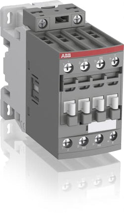
Ordering
1 piece
85364900
Popular Downloads
Dimensions
45 mm
101 mm
86 mm
0.4 kg
Technical
2
2
0
0
4P
IEC/EN 60947-1, IEC/EN 60947-4-1, UL 60335-2-40 LZGH2 A2L, UL 60947-1, UL 60947-4-1, CSA C22.2 No. 60335-2-40 LZGH2 A2L, CAN/CSA C22.2 No.60947-1, CAN/CSA C22.2 No.60947-4-1
Main Circuit 690 V
Control Circuit 50 / 60 Hz
Main Circuit 50 / 60 Hz
Control Circuit 50 / 60 Hz
Main Circuit 50 / 60 Hz
acc. to IEC 60947-4-1, Open Contactors Θ = 40 °C 55 A
(690 V) 40 °C 45 A
(690 V) 60 °C 40 A
(690 V) 70 °C 32 A
(690 V) 40 °C 45 A
(690 V) 60 °C 40 A
(690 V) 70 °C 32 A
(415 V) 60 °C 21.2 A
(440 V) 60 °C 20 A
(500 V) 60 °C 17.6 A
(690 V) 60 °C 10.5 A
(380 / 400 V) 60 °C 22 A
(220 / 230 / 240 V) 60 °C 23.2 A
(415 V) 60 °C 21.2 A
(440 V) 60 °C 20 A
(500 V) 60 °C 17.6 A
(690 V) 60 °C 10.5 A
(380 / 400 V) 60 °C 22 A
(220 / 230 / 240 V) 60 °C 23.2 A
(400 V) 11 kW
(415 V) 11 kW
(440 V) 11 kW
(500 V) 11 kW
(690 V) 9 kW
(220 / 230 / 240 V) 5.5 kW
(400 V) 11 kW
(415 V) 11 kW
(440 V) 11 kW
(500 V) 11 kW
(690 V) 9 kW
(220 / 230 / 240 V) 5.5 kW
at 40 °C Ambient Temp, in Free Air, from a Cold State 10 s 300 A
at 40 °C Ambient Temp, in Free Air, from a Cold State 15 min 55 A
at 40 °C Ambient Temp, in Free Air, from a Cold State 1 min 150 A
at 40 °C Ambient Temp, in Free Air, from a Cold State 1 s 450 A
at 40 °C Ambient Temp, in Free Air, from a Cold State 30 s 225 A
at 40 °C Ambient Temp, in Free Air, from a Cold State 10 s 300 A
at 40 °C Ambient Temp, in Free Air, from a Cold State 15 min 55 A
at 40 °C Ambient Temp, in Free Air, from a Cold State 1 min 150 A
at 40 °C Ambient Temp, in Free Air, from a Cold State 1 s 450 A
at 40 °C Ambient Temp, in Free Air, from a Cold State 30 s 225 A
acc. to IEC 60947-4-1 690 V
acc. to UL/CSA 600 V
acc. to IEC 60947-4-1 690 V
acc. to UL/CSA 600 V
6 kV
(AC-1) 600 cycles per hour
3600 cycles per hour
50 Hz 250 ... 500 V
60 Hz 250 ... 500 V
DC Operation 250 ... 500 V
50 Hz 250 ... 500 V
60 Hz 250 ... 500 V
DC Operation 250 ... 500 V
at Rated Operating Conditions AC-1 per Pole 1.6 W
at Rated Operating Conditions AC-3 per Pole 0.42 W
at Rated Operating Conditions AC-1 per Pole 1.6 W
at Rated Operating Conditions AC-3 per Pole 0.42 W
Between Coil De-energization and NC Contact Closing 13 ... 98 ms
Between Coil De-energization and NO Contact Opening 11 ... 95 ms
Between Coil Energization and NC Contact Opening 38 ... 90 ms
Between Coil Energization and NO Contact Closing 40 ... 95 ms
Between Coil De-energization and NC Contact Closing 13 ... 98 ms
Between Coil De-energization and NO Contact Opening 11 ... 95 ms
Between Coil Energization and NC Contact Opening 38 ... 90 ms
Between Coil Energization and NO Contact Closing 40 ... 95 ms
TH35-15 (35 x 15 mm Mounting Rail) acc. to IEC 60715
TH35-7.5 (35 x 7.5 mm Mounting Rail) acc. to IEC 60715
TH35-15 (35 x 15 mm Mounting Rail) acc. to IEC 60715
TH35-7.5 (35 x 7.5 mm Mounting Rail) acc. to IEC 60715
2 x M4 Screws Placed Diagonally
Flexible with Ferrule 1/2x 1.5 ... 16 mm²
Flexible with Insulated Ferrule 1/2x 1.5 ... 16 mm²
Rigid Solid 1/2x 1.5 ... 4 mm²
Rigid Stranded 1/2x 1.5 ... 16 mm²
Flexible with Ferrule 1/2x 1.5 ... 16 mm²
Flexible with Insulated Ferrule 1/2x 1.5 ... 16 mm²
Rigid Solid 1/2x 1.5 ... 4 mm²
Rigid Stranded 1/2x 1.5 ... 16 mm²
Flexible with Ferrule 1/2x 0.75 ... 2.5 mm²
Flexible with Insulated Ferrule 1x 0.75 ... 2.5 mm²
Flexible with Insulated Ferrule 2x 0.75 ... 1.5 mm²
Rigid Solid 1/2x 1 ... 2.5 mm²
Rigid Stranded 1/2x 1 ... 2.5 mm²
Flexible with Ferrule 1/2x 0.75 ... 2.5 mm²
Flexible with Insulated Ferrule 1x 0.75 ... 2.5 mm²
Flexible with Insulated Ferrule 2x 0.75 ... 1.5 mm²
Rigid Solid 1/2x 1 ... 2.5 mm²
Rigid Stranded 1/2x 1 ... 2.5 mm²
Control Circuit 10 mm
Main Circuit 12 mm
Control Circuit 10 mm
Main Circuit 12 mm
acc. to IEC 60529, IEC 60947-1, EN 60529 Coil Terminals IP20
acc. to IEC 60529, IEC 60947-1, EN 60529 Main Terminals IP20
acc. to IEC 60529, IEC 60947-1, EN 60529 Coil Terminals IP20
acc. to IEC 60529, IEC 60947-1, EN 60529 Main Terminals IP20
Control Circuit 1.2 N·m
Main Circuit 2.5 N·m
Control Circuit 1.2 N·m
Main Circuit 2.5 N·m
Screw Terminals
Block Contactor
Technical UL/CSA
Main Circuit 600 V
(600 V AC) 45 A
Rigid Solid 1/2x 16-10 AWG
Rigid Stranded 1/2x 16-6 AWG
Rigid Solid 1/2x 16-10 AWG
Rigid Stranded 1/2x 16-6 AWG
Rigid Solid 1/2x 18-14 AWG
Rigid Stranded 1/2x 18-14 AWG
Rigid Solid 1/2x 18-14 AWG
Rigid Stranded 1/2x 18-14 AWG
Control Circuit 11 in·lb
Main Circuit 22 in·lb
Control Circuit 11 in·lb
Main Circuit 22 in·lb
Environmental
Close to Contactor for Storage -60 ... +80 °C
Near Contactor for Operation in Free Air -40 ... 70 °C
Close to Contactor for Storage -60 ... +80 °C
Near Contactor for Operation in Free Air -40 ... 70 °C
Category B according to IEC 60947-1 Annex Q
Without Derating 3000 m
Closed, Shock Direction: A 30 g
Closed, Shock Direction: B1 25 g
Closed, Shock Direction: B2 15 g
Closed, Shock Direction: C1 25 g
Closed, Shock Direction: C2 25 g
Open, Shock Direction: A 25 g
Open, Shock Direction: B1 5 g
Open, Shock Direction: B2 10 g
Open, Shock Direction: C1 20 g
Open, Shock Direction: C2 20 g
Closed, Shock Direction: A 30 g
Closed, Shock Direction: B1 25 g
Closed, Shock Direction: B2 15 g
Closed, Shock Direction: C1 25 g
Closed, Shock Direction: C2 25 g
Open, Shock Direction: A 25 g
Open, Shock Direction: B1 5 g
Open, Shock Direction: B2 10 g
Open, Shock Direction: C1 20 g
Open, Shock Direction: C2 20 g
4g Closed Position & 2g Open position 5 ... 300 Hz
3
Material Compliance
Following EU Directive 2011/65/EU and Amendment 2015/863 July 22, 2019
Business To Business
5. Small Equipment (No External Dimension More Than 50 cm)
ABB EcoSolutions
Recycled Cardboard - 86 %
Recycled Metal - 28 %
Certificates and Declarations
Container Information
box 1 piece
87 mm
103 mm
47 mm
0.4 kg
3471523116443
box 18 piece
250 mm
300 mm
315 mm
14.4 kg
External Classifications and Standards
Q
EC000066 - Power contactor, AC switching
EC000066 - Power contactor, AC switching
EC000066 - Power contactor, AC switching
V11.0 : 27371003
39121529
4758 >> Iec Contactors
3705847
3211517
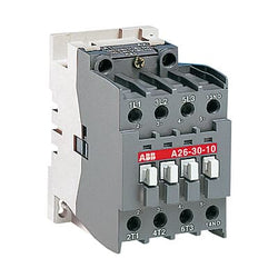
A26-30-01 220-230V 50Hz / 230-240V 60Hz Contactor.A26 contactors are mainly used for controlling 3-phase motors and generally for controlling power circuits up to 690 V AC or 220 V DC. The contactors can also be used for many other applications such as isolation, capacitor switching, lighting.

ABB
1SBL241001R8010 ABB - A26-30-10 220-230V 50Hz / 230-240V 60Hz
Sale price
€115,95
Only 7 units leftA26-30-10 220-230V 50Hz / 230-240V 60Hz Contactor