
 1 year warranty

Ordering
1 piece
85364900
Popular Downloads
Dimensions
45 mm
77 mm
86 mm
0.27 kg
Technical
2
2
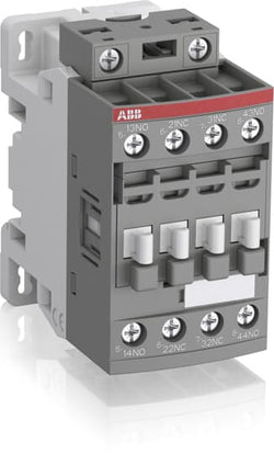
4P
IEC/EN 60947-1, IEC/EN 60947-5-1, UL 60335-2-40 LZGH2 A2L, UL 508, CSA C22.2 No. 60335-2-40 LZGH2 A2L, CSA C22.2 No. 14-13
Auxiliary Circuit 690 V
Auxiliary Circuit 50 / 60 Hz
Control Circuit 50 / 60 Hz
Auxiliary Circuit 50 / 60 Hz
Control Circuit 50 / 60 Hz
acc. to IEC 60947-5-1, Θ = 40 °C 16 A
(500 V) 2 A
(690 V) 2 A
(24 / 127 V) 6 A
(220 / 240 V) 4 A
(400 / 440 V) 3 A
(500 V) 2 A
(690 V) 2 A
(24 / 127 V) 6 A
(220 / 240 V) 4 A
(400 / 440 V) 3 A
(24 V) 6 A / 144 W
(48 V) 2.8 A / 134 W
(72 V) 1 A / 72 W
(110 V) 0.55 A / 60 W
(125 V) 0.55 A / 69 W
(220 V) 0.27 A / 60 W
(250 V) 0.27 A / 68 W
(400 V) 0.15 A / 60 W
(500 V) 0.13 A / 65 W
(600 V) 0.1 A / 60 W
(24 V) 6 A / 144 W
(48 V) 2.8 A / 134 W
(72 V) 1 A / 72 W
(110 V) 0.55 A / 60 W
(125 V) 0.55 A / 69 W
(220 V) 0.27 A / 60 W
(250 V) 0.27 A / 68 W
(400 V) 0.15 A / 60 W
(500 V) 0.13 A / 65 W
(600 V) 0.1 A / 60 W
for 0.1 s 140 A
for 1 s 100 A
for 0.1 s 140 A
for 1 s 100 A
acc. to IEC 60947-5-1 690 V
acc. to UL/CSA 600 V
acc. to IEC 60947-5-1 690 V
acc. to UL/CSA 600 V
6 kV
(AC-15) 1200 cycles per hour
(DC-13) 900 cycles per hour
(AC-15) 1200 cycles per hour
(DC-13) 900 cycles per hour
6000 cycles per hour
50 Hz 100 ... 250 V
60 Hz 100 ... 250 V
DC Operation 100 ... 250 V
50 Hz 100 ... 250 V
60 Hz 100 ... 250 V
DC Operation 100 ... 250 V
Between Coil De-energization and NC Contact Closing 13 ... 98 ms
Between Coil De-energization and NO Contact Opening 11 ... 95 ms
Between Coil Energization and NC Contact Opening 38 ... 90 ms
Between Coil Energization and NO Contact Closing 40 ... 95 ms
Between Coil De-energization and NC Contact Closing 13 ... 98 ms
Between Coil De-energization and NO Contact Opening 11 ... 95 ms
Between Coil Energization and NC Contact Opening 38 ... 90 ms
Between Coil Energization and NO Contact Closing 40 ... 95 ms
TH35-15 (35 x 15 mm Mounting Rail) acc. to IEC 60715
TH35-7.5 (35 x 7.5 mm Mounting Rail) acc. to IEC 60715
TH35-15 (35 x 15 mm Mounting Rail) acc. to IEC 60715
TH35-7.5 (35 x 7.5 mm Mounting Rail) acc. to IEC 60715
2 x M4 Screws Placed Diagonally
Flexible with Ferrule 1/2x 0.75 ... 2.5 mm²
Flexible with Insulated Ferrule 1x 0.75 ... 2.5 mm²
Flexible with Insulated Ferrule 2x 0.75 ... 1.5 mm²
Rigid Solid 1/2x 1 ... 2.5 mm²
Rigid Stranded 1/2x 1 ... 2.5 mm²
Flexible with Ferrule 1/2x 0.75 ... 2.5 mm²
Flexible with Insulated Ferrule 1x 0.75 ... 2.5 mm²
Flexible with Insulated Ferrule 2x 0.75 ... 1.5 mm²
Rigid Solid 1/2x 1 ... 2.5 mm²
Rigid Stranded 1/2x 1 ... 2.5 mm²
Flexible with Ferrule 1/2x 0.75 ... 2.5 mm²
Flexible with Insulated Ferrule 1x 0.75 ... 2.5 mm²
Flexible with Insulated Ferrule 2x 0.75 ... 1.5 mm²
Rigid Solid 1/2x 1 ... 2.5 mm²
Rigid Stranded 1/2x 1 ... 2.5 mm²
Flexible with Ferrule 1/2x 0.75 ... 2.5 mm²
Flexible with Insulated Ferrule 1x 0.75 ... 2.5 mm²
Flexible with Insulated Ferrule 2x 0.75 ... 1.5 mm²
Rigid Solid 1/2x 1 ... 2.5 mm²
Rigid Stranded 1/2x 1 ... 2.5 mm²
Auxiliary Circuit 10 mm
Control Circuit 10 mm
Auxiliary Circuit 10 mm
Control Circuit 10 mm
acc. to IEC 60529, IEC 60947-1, EN 60529 Auxiliary Terminals IP20
acc. to IEC 60529, IEC 60947-1, EN 60529 Coil Terminals IP20
acc. to IEC 60529, IEC 60947-1, EN 60529 Auxiliary Terminals IP20
acc. to IEC 60529, IEC 60947-1, EN 60529 Coil Terminals IP20
Auxiliary Circuit 1.2 N·m
Control Circuit 1.2 N·m
Auxiliary Circuit 1.2 N·m
Control Circuit 1.2 N·m
Screw Terminals
Block Contactor Relay
Technical UL/CSA
Rigid Solid 1/2x 18-14 AWG
Rigid Stranded 1/2x 18-14 AWG
Rigid Solid 1/2x 18-14 AWG
Rigid Stranded 1/2x 18-14 AWG
Auxiliary Circuit 11 in·lb
Control Circuit 11 in·lb
Auxiliary Circuit 11 in·lb
Control Circuit 11 in·lb
Environmental
Close to Contactor for Storage -60 ... +80 °C
Near Contactor for Operation in Free Air -40 ... 70 °C
Close to Contactor for Storage -60 ... +80 °C
Near Contactor for Operation in Free Air -40 ... 70 °C
Category B according to IEC 60947-1 Annex Q
Without Derating 3000 m
Closed, Shock Direction: B1 25 g
Open, Shock Direction: B1 5 g
Shock Direction: A 30 g
Shock Direction: B2 15 g
Shock Direction: C1 25 g
Shock Direction: C2 25 g
Closed, Shock Direction: B1 25 g
Open, Shock Direction: B1 5 g
Shock Direction: A 30 g
Shock Direction: B2 15 g
Shock Direction: C1 25 g
Shock Direction: C2 25 g
4g Closed Position & 2g Open position 5 ... 300 Hz
3
Material Compliance
Following EU Directive 2011/65/EU and Amendment 2015/863 July 22, 2019
5611a638-de62-42f4-ab21-bce6bffa1c76 China
f3bae351-c0cd-4bab-bf7b-6bd0db1d1f37 Estonia
1885854c-d808-4403-a683-cfc666ca8ed9 Finland
a8a790c6-8865-42dc-9a16-25c71c579cd4 Hungary
59605740-7ed4-4540-b17c-1518303e80a5 France
cc44becd-3e4c-4438-a018-76c100575d4a Czech Republic
f76f9696-c830-41c5-b415-8c237939b7eb Germany
6f76ebd8-1e69-449a-976c-6ff242c1e41a Croatia
9f56f5f1-8011-409e-8370-61a20483a92f Germany
d4147311-807d-4704-8816-6937315d9f78 Poland
ce59d800-bdf2-465e-af6f-fe6d1ba44fd1 France
d62686b9-6abd-4dd6-b569-b45f1df84332 Sweden
09ef808a-e3aa-4c6d-a04a-aebb099d2357 Germany
a4ec99a6-f169-44e5-b94e-26a2bc67bc67 Portugal
8d8029c9-ad99-4e21-a5e9-7fc522e5e887 Denmark
f4311c29-4ca4-44e2-b3ec-25dd1aba9a81 Germany
f62bf0b2-925a-4c1e-90c0-0dd30d54e965 Germany
9f85c2e0-013e-4516-8563-37b66ba26fcd Bulgaria
8101e312-0d84-4d34-9a04-330462c44519 Sweden
d3407bd3-bf30-4d85-acd5-2d32b1c79fc1 Belgium
b0226ce6-f0c7-40b5-8b57-5ec6648fe56b Spain
016176d6-283d-44d6-b525-56f0360a6d44 Belgium
0b14c632-d6ac-49d1-8487-ee8816a82d15 Greece
8e0a69aa-6cf3-4534-a91e-d73643b77111 Norway
cbcd985c-25da-4de1-9f2f-20d6be1e5549 Poland
aec57acf-fcca-4684-87ea-bf712a874385 Poland
53829389-b1d3-4434-b42f-a362e318a659 Netherlands
5de59291-108d-468f-a1d0-570d71b20dda Hungary
f3bae351-c0cd-4bab-bf7b-6bd0db1d1f37 Estonia
1885854c-d808-4403-a683-cfc666ca8ed9 Finland
a8a790c6-8865-42dc-9a16-25c71c579cd4 Hungary
59605740-7ed4-4540-b17c-1518303e80a5 France
cc44becd-3e4c-4438-a018-76c100575d4a Czech Republic
f76f9696-c830-41c5-b415-8c237939b7eb Germany
6f76ebd8-1e69-449a-976c-6ff242c1e41a Croatia
9f56f5f1-8011-409e-8370-61a20483a92f Germany
d4147311-807d-4704-8816-6937315d9f78 Poland
ce59d800-bdf2-465e-af6f-fe6d1ba44fd1 France
Business To Business
5. Small Equipment (No External Dimension More Than 50 cm)
ABB EcoSolutions
Recycled Cardboard - 86 %
Recycled Metal - 28 %
Certificates and Declarations
Container Information
box 1 piece
87 mm
79 mm
47 mm
0.27 kg
3471523100138
box 27 piece
250 mm
300 mm
315 mm
14.58 kg
External Classifications and Standards
K
EC000196 - Contactor relay
EC000196 - Contactor relay
EC000196 - Contactor relay
V11.0 : 27371001
39121529
4763 >> Power contactor, DC switching
3706401
3211448

Ordering
1 piece
85364900
Popular Downloads
Dimensions
45 mm
77 mm
86 mm
0.27 kg
Technical
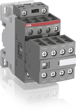
3
1
4P
IEC/EN 60947-1, IEC/EN 60947-5-1, UL 60335-2-40 LZGH2 A2L, UL 508, CSA C22.2 No. 60335-2-40 LZGH2 A2L, CSA C22.2 No. 14-13
Auxiliary Circuit 690 V
Auxiliary Circuit 50 / 60 Hz
Control Circuit 50 / 60 Hz
Auxiliary Circuit 50 / 60 Hz
Control Circuit 50 / 60 Hz
acc. to IEC 60947-5-1, Θ = 40 °C 16 A
(500 V) 2 A
(690 V) 2 A
(24 / 127 V) 6 A
(220 / 240 V) 4 A
(400 / 440 V) 3 A
(500 V) 2 A
(690 V) 2 A
(24 / 127 V) 6 A
(220 / 240 V) 4 A
(400 / 440 V) 3 A
(24 V) 6 A / 144 W
(48 V) 2.8 A / 134 W
(72 V) 1 A / 72 W
(110 V) 0.55 A / 60 W
(125 V) 0.55 A / 69 W
(220 V) 0.27 A / 60 W
(250 V) 0.27 A / 68 W
(400 V) 0.15 A / 60 W
(500 V) 0.13 A / 65 W
(600 V) 0.1 A / 60 W
(24 V) 6 A / 144 W
(48 V) 2.8 A / 134 W
(72 V) 1 A / 72 W
(110 V) 0.55 A / 60 W
(125 V) 0.55 A / 69 W
(220 V) 0.27 A / 60 W
(250 V) 0.27 A / 68 W
(400 V) 0.15 A / 60 W
(500 V) 0.13 A / 65 W
(600 V) 0.1 A / 60 W
for 0.1 s 140 A
for 1 s 100 A
for 0.1 s 140 A
for 1 s 100 A
acc. to IEC 60947-5-1 690 V
acc. to UL/CSA 600 V
acc. to IEC 60947-5-1 690 V
acc. to UL/CSA 600 V
6 kV
(AC-15) 1200 cycles per hour
(DC-13) 900 cycles per hour
(AC-15) 1200 cycles per hour
(DC-13) 900 cycles per hour
6000 cycles per hour
50 Hz 100 ... 250 V
60 Hz 100 ... 250 V
DC Operation 100 ... 250 V
50 Hz 100 ... 250 V
60 Hz 100 ... 250 V
DC Operation 100 ... 250 V
Between Coil De-energization and NC Contact Closing 13 ... 98 ms
Between Coil De-energization and NO Contact Opening 11 ... 95 ms
Between Coil Energization and NC Contact Opening 38 ... 90 ms
Between Coil Energization and NO Contact Closing 40 ... 95 ms
Between Coil De-energization and NC Contact Closing 13 ... 98 ms
Between Coil De-energization and NO Contact Opening 11 ... 95 ms
Between Coil Energization and NC Contact Opening 38 ... 90 ms
Between Coil Energization and NO Contact Closing 40 ... 95 ms
TH35-15 (35 x 15 mm Mounting Rail) acc. to IEC 60715
TH35-7.5 (35 x 7.5 mm Mounting Rail) acc. to IEC 60715
TH35-15 (35 x 15 mm Mounting Rail) acc. to IEC 60715
TH35-7.5 (35 x 7.5 mm Mounting Rail) acc. to IEC 60715
2 x M4 Screws Placed Diagonally
Flexible with Ferrule 1/2x 0.75 ... 2.5 mm²
Flexible with Insulated Ferrule 1x 0.75 ... 2.5 mm²
Flexible with Insulated Ferrule 2x 0.75 ... 1.5 mm²
Rigid Solid 1/2x 1 ... 2.5 mm²
Rigid Stranded 1/2x 1 ... 2.5 mm²
Flexible with Ferrule 1/2x 0.75 ... 2.5 mm²
Flexible with Insulated Ferrule 1x 0.75 ... 2.5 mm²
Flexible with Insulated Ferrule 2x 0.75 ... 1.5 mm²
Rigid Solid 1/2x 1 ... 2.5 mm²
Rigid Stranded 1/2x 1 ... 2.5 mm²
Flexible with Ferrule 1/2x 0.75 ... 2.5 mm²
Flexible with Insulated Ferrule 1x 0.75 ... 2.5 mm²
Flexible with Insulated Ferrule 2x 0.75 ... 1.5 mm²
Rigid Solid 1/2x 1 ... 2.5 mm²
Rigid Stranded 1/2x 1 ... 2.5 mm²
Flexible with Ferrule 1/2x 0.75 ... 2.5 mm²
Flexible with Insulated Ferrule 1x 0.75 ... 2.5 mm²
Flexible with Insulated Ferrule 2x 0.75 ... 1.5 mm²
Rigid Solid 1/2x 1 ... 2.5 mm²
Rigid Stranded 1/2x 1 ... 2.5 mm²
Auxiliary Circuit 10 mm
Control Circuit 10 mm
Auxiliary Circuit 10 mm
Control Circuit 10 mm
acc. to IEC 60529, IEC 60947-1, EN 60529 Auxiliary Terminals IP20
acc. to IEC 60529, IEC 60947-1, EN 60529 Coil Terminals IP20
acc. to IEC 60529, IEC 60947-1, EN 60529 Auxiliary Terminals IP20
acc. to IEC 60529, IEC 60947-1, EN 60529 Coil Terminals IP20
Auxiliary Circuit 1.2 N·m
Control Circuit 1.2 N·m
Auxiliary Circuit 1.2 N·m
Control Circuit 1.2 N·m
Screw Terminals
Block Contactor Relay
Technical UL/CSA
Rigid Solid 1/2x 18-14 AWG
Rigid Stranded 1/2x 18-14 AWG
Rigid Solid 1/2x 18-14 AWG
Rigid Stranded 1/2x 18-14 AWG
Auxiliary Circuit 11 in·lb
Control Circuit 11 in·lb
Auxiliary Circuit 11 in·lb
Control Circuit 11 in·lb
Environmental
Close to Contactor for Storage -60 ... +80 °C
Near Contactor for Operation in Free Air -40 ... 70 °C
Close to Contactor for Storage -60 ... +80 °C
Near Contactor for Operation in Free Air -40 ... 70 °C
Category B according to IEC 60947-1 Annex Q
Without Derating 3000 m
Closed, Shock Direction: B1 25 g
Open, Shock Direction: B1 5 g
Shock Direction: A 30 g
Shock Direction: B2 15 g
Shock Direction: C1 25 g
Shock Direction: C2 25 g
Closed, Shock Direction: B1 25 g
Open, Shock Direction: B1 5 g
Shock Direction: A 30 g
Shock Direction: B2 15 g
Shock Direction: C1 25 g
Shock Direction: C2 25 g
4g Closed Position & 2g Open position 5 ... 300 Hz
3
Material Compliance
Following EU Directive 2011/65/EU and Amendment 2015/863 July 22, 2019
a000906b-ee90-4914-a705-5dbe89ad884e China
08ed39a6-d5f0-4b77-9a7c-3ad1a5fdfce0 France
50dfbd34-ce1f-4ba9-a9c8-8ea154f200e0 Sweden
e32fc31c-ba09-4e2d-b9c0-5153dee29d4b Croatia
dd5d464d-48d7-4e22-a751-c9cb6a7c51e5 Czech Republic
05c537b2-74e1-4315-b1bd-cc3488f94469 Germany
6d615b49-4560-4f9c-8a62-a6ca6cbaa101 Denmark
fcf6a977-ffc4-4a13-aa36-46647fc45834 Bulgaria
0371d898-49b5-4aa0-8544-7cf410e6f415 Belgium
7f7fe1d5-690b-420b-816c-af5ad74f49e7 Greece
06b23ae7-55ec-4400-9b4e-243a62d05505 Spain
d2055ce8-9d59-4388-b13a-6557cc1c8e49 Portugal
b79060f8-ef03-45d7-a748-e435c580b744 Belgium
3b4eb8fa-4169-4455-8d03-e5d0ed0176d5 Finland
6a9db7a1-8d74-4bdf-b9a1-706b76f087f3 Hungary
ef3b0b48-babb-42be-bd15-06d832124a2d Estonia
c1bdd10d-447a-498f-90b0-b4219b53fcc8 Hungary
c45981e2-78a5-4d77-b673-a0235182729b Netherlands
c40d1270-6aae-4508-ae94-58d2f0e5153d Poland
169c4d16-87fc-495a-a480-a72d9b0c074f Norway
a9936961-d1d2-49da-8833-c4767539bff9 Poland
b4208a2c-0fdb-49ba-8b79-48f8d32ae739 Germany
8c80b00d-c7f3-4088-b4ed-a8db0b3d4b35 France
ed5b84ba-c80a-4150-9f47-6b798bf3e6d4 Sweden
6ec38270-a4eb-49e5-a8b2-c40a8b55b0cf Germany
f711759d-136f-4625-8b4a-5528cd99b329 Germany
ebabf4ac-94de-4cc7-a6fe-b8d814487367 Germany
970cf98c-b19a-4e5b-9dba-765b1c7b9f36 Poland
08ed39a6-d5f0-4b77-9a7c-3ad1a5fdfce0 France
50dfbd34-ce1f-4ba9-a9c8-8ea154f200e0 Sweden
e32fc31c-ba09-4e2d-b9c0-5153dee29d4b Croatia
dd5d464d-48d7-4e22-a751-c9cb6a7c51e5 Czech Republic
05c537b2-74e1-4315-b1bd-cc3488f94469 Germany
6d615b49-4560-4f9c-8a62-a6ca6cbaa101 Denmark
fcf6a977-ffc4-4a13-aa36-46647fc45834 Bulgaria
0371d898-49b5-4aa0-8544-7cf410e6f415 Belgium
7f7fe1d5-690b-420b-816c-af5ad74f49e7 Greece
06b23ae7-55ec-4400-9b4e-243a62d05505 Spain
Business To Business
5. Small Equipment (No External Dimension More Than 50 cm)
ABB EcoSolutions
Recycled Cardboard - 86 %
Recycled Metal - 28 %
Certificates and Declarations
Container Information
box 1 piece
87 mm
79 mm
47 mm
0.27 kg
3471523100237
box 27 piece
250 mm
300 mm
315 mm
14.58 kg
External Classifications and Standards
K
EC000196 - Contactor relay
EC000196 - Contactor relay
EC000196 - Contactor relay
V11.0 : 27371001
39121529
4763 >> Power contactor, DC switching
3706408
3211452

Ordering
1 piece
85364900
Popular Downloads
Dimensions
45 mm
77 mm
86 mm
0.27 kg
Technical
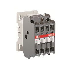
4
0
4P
IEC/EN 60947-1, IEC/EN 60947-5-1, UL 60335-2-40 LZGH2 A2L, UL 508, CSA C22.2 No. 60335-2-40 LZGH2 A2L, CSA C22.2 No. 14-13
Auxiliary Circuit 690 V
Auxiliary Circuit 50 / 60 Hz
Control Circuit 50 / 60 Hz
Auxiliary Circuit 50 / 60 Hz
Control Circuit 50 / 60 Hz
acc. to IEC 60947-5-1, Θ = 40 °C 16 A
(500 V) 2 A
(690 V) 2 A
(24 / 127 V) 6 A
(220 / 240 V) 4 A
(400 / 440 V) 3 A
(500 V) 2 A
(690 V) 2 A
(24 / 127 V) 6 A
(220 / 240 V) 4 A
(400 / 440 V) 3 A
(24 V) 6 A / 144 W
(48 V) 2.8 A / 134 W
(72 V) 1 A / 72 W
(110 V) 0.55 A / 60 W
(125 V) 0.55 A / 69 W
(220 V) 0.27 A / 60 W
(250 V) 0.27 A / 68 W
(400 V) 0.15 A / 60 W
(500 V) 0.13 A / 65 W
(600 V) 0.1 A / 60 W
(24 V) 6 A / 144 W
(48 V) 2.8 A / 134 W
(72 V) 1 A / 72 W
(110 V) 0.55 A / 60 W
(125 V) 0.55 A / 69 W
(220 V) 0.27 A / 60 W
(250 V) 0.27 A / 68 W
(400 V) 0.15 A / 60 W
(500 V) 0.13 A / 65 W
(600 V) 0.1 A / 60 W
for 0.1 s 140 A
for 1 s 100 A
for 0.1 s 140 A
for 1 s 100 A
acc. to IEC 60947-5-1 690 V
acc. to UL/CSA 600 V
acc. to IEC 60947-5-1 690 V
acc. to UL/CSA 600 V
6 kV
(AC-15) 1200 cycles per hour
(DC-13) 900 cycles per hour
(AC-15) 1200 cycles per hour
(DC-13) 900 cycles per hour
6000 cycles per hour
50 Hz 100 ... 250 V
60 Hz 100 ... 250 V
DC Operation 100 ... 250 V
50 Hz 100 ... 250 V
60 Hz 100 ... 250 V
DC Operation 100 ... 250 V
Between Coil De-energization and NC Contact Closing 13 ... 98 ms
Between Coil De-energization and NO Contact Opening 11 ... 95 ms
Between Coil Energization and NC Contact Opening 38 ... 90 ms
Between Coil Energization and NO Contact Closing 40 ... 95 ms
Between Coil De-energization and NC Contact Closing 13 ... 98 ms
Between Coil De-energization and NO Contact Opening 11 ... 95 ms
Between Coil Energization and NC Contact Opening 38 ... 90 ms
Between Coil Energization and NO Contact Closing 40 ... 95 ms
TH35-15 (35 x 15 mm Mounting Rail) acc. to IEC 60715
TH35-7.5 (35 x 7.5 mm Mounting Rail) acc. to IEC 60715
TH35-15 (35 x 15 mm Mounting Rail) acc. to IEC 60715
TH35-7.5 (35 x 7.5 mm Mounting Rail) acc. to IEC 60715
2 x M4 Screws Placed Diagonally
Flexible with Ferrule 1/2x 0.75 ... 2.5 mm²
Flexible with Insulated Ferrule 1x 0.75 ... 2.5 mm²
Flexible with Insulated Ferrule 2x 0.75 ... 1.5 mm²
Rigid Solid 1/2x 1 ... 2.5 mm²
Rigid Stranded 1/2x 1 ... 2.5 mm²
Flexible with Ferrule 1/2x 0.75 ... 2.5 mm²
Flexible with Insulated Ferrule 1x 0.75 ... 2.5 mm²
Flexible with Insulated Ferrule 2x 0.75 ... 1.5 mm²
Rigid Solid 1/2x 1 ... 2.5 mm²
Rigid Stranded 1/2x 1 ... 2.5 mm²
Flexible with Ferrule 1/2x 0.75 ... 2.5 mm²
Flexible with Insulated Ferrule 1x 0.75 ... 2.5 mm²
Flexible with Insulated Ferrule 2x 0.75 ... 1.5 mm²
Rigid Solid 1/2x 1 ... 2.5 mm²
Rigid Stranded 1/2x 1 ... 2.5 mm²
Flexible with Ferrule 1/2x 0.75 ... 2.5 mm²
Flexible with Insulated Ferrule 1x 0.75 ... 2.5 mm²
Flexible with Insulated Ferrule 2x 0.75 ... 1.5 mm²
Rigid Solid 1/2x 1 ... 2.5 mm²
Rigid Stranded 1/2x 1 ... 2.5 mm²
Auxiliary Circuit 10 mm
Control Circuit 10 mm
Auxiliary Circuit 10 mm
Control Circuit 10 mm
acc. to IEC 60529, IEC 60947-1, EN 60529 Auxiliary Terminals IP20
acc. to IEC 60529, IEC 60947-1, EN 60529 Coil Terminals IP20
acc. to IEC 60529, IEC 60947-1, EN 60529 Auxiliary Terminals IP20
acc. to IEC 60529, IEC 60947-1, EN 60529 Coil Terminals IP20
Auxiliary Circuit 1.2 N·m
Control Circuit 1.2 N·m
Auxiliary Circuit 1.2 N·m
Control Circuit 1.2 N·m
Screw Terminals
Block Contactor Relay
Technical UL/CSA
Rigid Solid 1/2x 18-14 AWG
Rigid Stranded 1/2x 18-14 AWG
Rigid Solid 1/2x 18-14 AWG
Rigid Stranded 1/2x 18-14 AWG
Auxiliary Circuit 11 in·lb
Control Circuit 11 in·lb
Auxiliary Circuit 11 in·lb
Control Circuit 11 in·lb
Environmental
Close to Contactor for Storage -60 ... +80 °C
Near Contactor for Operation in Free Air -40 ... 70 °C
Close to Contactor for Storage -60 ... +80 °C
Near Contactor for Operation in Free Air -40 ... 70 °C
Category B according to IEC 60947-1 Annex Q
Without Derating 3000 m
Closed, Shock Direction: B1 25 g
Open, Shock Direction: B1 5 g
Shock Direction: A 30 g
Shock Direction: B2 15 g
Shock Direction: C1 25 g
Shock Direction: C2 25 g
Closed, Shock Direction: B1 25 g
Open, Shock Direction: B1 5 g
Shock Direction: A 30 g
Shock Direction: B2 15 g
Shock Direction: C1 25 g
Shock Direction: C2 25 g
4g Closed Position & 2g Open position 5 ... 300 Hz
3
Material Compliance
Following EU Directive 2011/65/EU and Amendment 2015/863 July 22, 2019
7f157d16-dd5e-4b7b-9580-f91e0f6278a7 China
dc6fcf2e-d541-43a2-9f4b-6ca86e1f25dd Czech Republic
7435d2de-2aa7-4a6a-9c2b-ada758f086b2 Germany
ddab8a04-b0e1-4615-a03a-ec81c79ac303 Croatia
2582c948-b266-4607-a80c-ee6f8be2e314 Poland
6d939e8d-72a0-42c9-af49-1e8ad30e67ef Poland
37d088d2-7c79-477f-87ca-33f1e15bdfa9 Netherlands
51b74668-515d-4dfb-8ff3-c46ca8a94b9d Hungary
a25eaa8b-f543-4849-b85f-6f6f097736fe Norway
b8475ac9-d9ab-4215-b695-48163578f8d4 Finland
1cf00ec8-e95d-4059-bfbd-17813d26470f Hungary
5e716a07-653a-4d45-bd83-3801cc78fda8 Estonia
75441054-627a-48f0-9603-c33e2acc3f40 Denmark
66b048dc-3364-4b04-a56e-81a3167747b3 Bulgaria
501b87e6-616e-4883-a911-fabbea35f0d6 Greece
2520be6a-a05a-4ed8-b6a8-07a00ecc423c Germany
a636f80b-7ae5-4eff-8102-bb5a083232ff Portugal
cc935eb2-9cfd-4558-aba6-09f9bf79f705 Spain
c7e0338e-c1cd-413b-a689-afda05efb11b Belgium
c7e26a42-ff75-43a4-9481-97875b523bd3 Belgium
fe1361a7-80aa-46b9-9748-0c8880ab5e2b France
9a52a025-058e-4344-aee3-d0de210c229b Sweden
aa49fb37-9f0a-42e4-80f3-31b729e1ac8c Germany
bbc87858-0799-4ce7-8c83-8999a279a25b Germany
f5168fa0-681f-4b62-b7d2-eb09e7edf164 Poland
aae6891e-ab71-42b7-b7fb-dc5ae946b2c2 Germany
31bfffaf-82e2-430d-93a5-8bb50db96639 Sweden
5d806e57-9d31-41da-b4f8-356ad2696755 France
dc6fcf2e-d541-43a2-9f4b-6ca86e1f25dd Czech Republic
7435d2de-2aa7-4a6a-9c2b-ada758f086b2 Germany
ddab8a04-b0e1-4615-a03a-ec81c79ac303 Croatia
2582c948-b266-4607-a80c-ee6f8be2e314 Poland
6d939e8d-72a0-42c9-af49-1e8ad30e67ef Poland
37d088d2-7c79-477f-87ca-33f1e15bdfa9 Netherlands
51b74668-515d-4dfb-8ff3-c46ca8a94b9d Hungary
a25eaa8b-f543-4849-b85f-6f6f097736fe Norway
b8475ac9-d9ab-4215-b695-48163578f8d4 Finland
1cf00ec8-e95d-4059-bfbd-17813d26470f Hungary
Business To Business
5. Small Equipment (No External Dimension More Than 50 cm)
ABB EcoSolutions
Recycled Cardboard - 86 %
Recycled Metal - 28 %
Certificates and Declarations
Container Information
box 1 piece
87 mm
79 mm
47 mm
0.27 kg
3471523100039
box 27 piece
250 mm
300 mm
315 mm
14.58 kg
External Classifications and Standards
K
EC000196 - Contactor relay
EC000196 - Contactor relay
EC000196 - Contactor relay
V11.0 : 27371001
39121529
4763 >> Power contactor, DC switching
3706415
3211456
Ordering
1 piece
85364900
Popular Downloads
Dimensions
45 mm
110.5 mm
86 mm
0.32 kg
Technical
4
4
8P
IEC/EN 60947-1, IEC/EN 60947-5-1, UL 60335-2-40 LZGH2 A2L, UL 508, CSA C22.2 No. 60335-2-40 LZGH2 A2L, CSA C22.2 No. 14-13
Auxiliary Circuit 690 V
Auxiliary Circuit 50 / 60 Hz
Control Circuit 50 / 60 Hz
Auxiliary Circuit 50 / 60 Hz
Control Circuit 50 / 60 Hz
acc. to IEC 60947-5-1, Θ = 40 °C 16 A
(500 V) 2 A
(690 V) 2 A
(24 / 127 V) 6 A
(220 / 240 V) 4 A
(400 / 440 V) 3 A
(500 V) 2 A
(690 V) 2 A
(24 / 127 V) 6 A
(220 / 240 V) 4 A
(400 / 440 V) 3 A
(24 V) 6 A / 144 W
(48 V) 2.8 A / 134 W
(72 V) 1 A / 72 W
(110 V) 0.55 A / 60 W
(125 V) 0.55 A / 69 W
(220 V) 0.27 A / 60 W
(250 V) 0.27 A / 68 W
(400 V) 0.15 A / 60 W
(500 V) 0.13 A / 65 W
(600 V) 0.1 A / 60 W
(24 V) 6 A / 144 W
(48 V) 2.8 A / 134 W
(72 V) 1 A / 72 W
(110 V) 0.55 A / 60 W
(125 V) 0.55 A / 69 W
(220 V) 0.27 A / 60 W
(250 V) 0.27 A / 68 W
(400 V) 0.15 A / 60 W
(500 V) 0.13 A / 65 W
(600 V) 0.1 A / 60 W
for 0.1 s 140 A
for 1 s 100 A
for 0.1 s 140 A
for 1 s 100 A
acc. to IEC 60947-5-1 690 V
acc. to UL/CSA 600 V
acc. to IEC 60947-5-1 690 V
acc. to UL/CSA 600 V
6 kV
(AC-15) 1200 cycles per hour
(DC-13) 900 cycles per hour
(AC-15) 1200 cycles per hour
(DC-13) 900 cycles per hour
6000 cycles per hour
50 Hz 100 ... 250 V
60 Hz 100 ... 250 V
DC Operation 100 ... 250 V
50 Hz 100 ... 250 V
60 Hz 100 ... 250 V
DC Operation 100 ... 250 V
Between Coil De-energization and NC Contact Closing 13 ... 98 ms
Between Coil De-energization and NO Contact Opening 11 ... 95 ms
Between Coil Energization and NC Contact Opening 38 ... 90 ms
Between Coil Energization and NO Contact Closing 40 ... 95 ms
Between Coil De-energization and NC Contact Closing 13 ... 98 ms
Between Coil De-energization and NO Contact Opening 11 ... 95 ms
Between Coil Energization and NC Contact Opening 38 ... 90 ms
Between Coil Energization and NO Contact Closing 40 ... 95 ms
TH35-15 (35 x 15 mm Mounting Rail) acc. to IEC 60715
TH35-7.5 (35 x 7.5 mm Mounting Rail) acc. to IEC 60715
TH35-15 (35 x 15 mm Mounting Rail) acc. to IEC 60715
TH35-7.5 (35 x 7.5 mm Mounting Rail) acc. to IEC 60715
2 x M4 Screws Placed Diagonally
Flexible with Ferrule 1/2x 0.75 ... 2.5 mm²
Flexible with Insulated Ferrule 1x 0.75 ... 2.5 mm²
Flexible with Insulated Ferrule 2x 0.75 ... 1.5 mm²
Rigid Solid 1/2x 1 ... 2.5 mm²
Rigid Stranded 1/2x 1 ... 2.5 mm²
Flexible with Ferrule 1/2x 0.75 ... 2.5 mm²
Flexible with Insulated Ferrule 1x 0.75 ... 2.5 mm²
Flexible with Insulated Ferrule 2x 0.75 ... 1.5 mm²
Rigid Solid 1/2x 1 ... 2.5 mm²
Rigid Stranded 1/2x 1 ... 2.5 mm²
Flexible with Ferrule 1/2x 0.75 ... 2.5 mm²
Flexible with Insulated Ferrule 1x 0.75 ... 2.5 mm²
Flexible with Insulated Ferrule 2x 0.75 ... 1.5 mm²
Rigid Solid 1/2x 1 ... 2.5 mm²
Rigid Stranded 1/2x 1 ... 2.5 mm²
Flexible with Ferrule 1/2x 0.75 ... 2.5 mm²
Flexible with Insulated Ferrule 1x 0.75 ... 2.5 mm²
Flexible with Insulated Ferrule 2x 0.75 ... 1.5 mm²
Rigid Solid 1/2x 1 ... 2.5 mm²
Rigid Stranded 1/2x 1 ... 2.5 mm²
Auxiliary Circuit 10 mm
Control Circuit 10 mm
Auxiliary Circuit 10 mm
Control Circuit 10 mm
acc. to IEC 60529, IEC 60947-1, EN 60529 Auxiliary Terminals IP20
acc. to IEC 60529, IEC 60947-1, EN 60529 Coil Terminals IP20
acc. to IEC 60529, IEC 60947-1, EN 60529 Auxiliary Terminals IP20
acc. to IEC 60529, IEC 60947-1, EN 60529 Coil Terminals IP20
Auxiliary Circuit 1.2 N·m
Control Circuit 1.2 N·m
Auxiliary Circuit 1.2 N·m
Control Circuit 1.2 N·m
Screw Terminals
Block Contactor Relay
Technical UL/CSA
Rigid Solid 1/2x 18-14 AWG
Rigid Stranded 1/2x 18-14 AWG
Rigid Solid 1/2x 18-14 AWG
Rigid Stranded 1/2x 18-14 AWG
Auxiliary Circuit 11 in·lb
Control Circuit 11 in·lb
Auxiliary Circuit 11 in·lb
Control Circuit 11 in·lb
Environmental
Close to Contactor for Storage -60 ... +80 °C
Near Contactor for Operation in Free Air -40 ... 70 °C
Close to Contactor for Storage -60 ... +80 °C
Near Contactor for Operation in Free Air -40 ... 70 °C
Category B according to IEC 60947-1 Annex Q
Without Derating 3000 m
Closed, Shock Direction: B1 25 g
Open, Shock Direction: B1 5 g
Shock Direction: A 30 g
Shock Direction: B2 15 g
Shock Direction: C1 25 g
Shock Direction: C2 25 g
Closed, Shock Direction: B1 25 g
Open, Shock Direction: B1 5 g
Shock Direction: A 30 g
Shock Direction: B2 15 g
Shock Direction: C1 25 g
Shock Direction: C2 25 g
4g Closed Position & 2g Open position 5 ... 300 Hz
3
Material Compliance
Following EU Directive 2011/65/EU and Amendment 2015/863 July 22, 2019
Business To Business
5. Small Equipment (No External Dimension More Than 50 cm)
ABB EcoSolutions
Recycled Cardboard - 86 %
Recycled Metal - 28 %
Certificates and Declarations
Container Information
box 1 piece
87 mm
113 mm
47 mm
0.32 kg
3471523100732
box 18 piece
250 mm
300 mm
315 mm
11.52 kg
External Classifications and Standards
K
EC000196 - Contactor relay
EC000196 - Contactor relay
EC000196 - Contactor relay
V11.0 : 27371001
39121529
4763 >> Power contactor, DC switching
3706422

Ordering
1 piece
85364900
Popular Downloads
Dimensions
45 mm
110.5 mm
86 mm
0.32 kg
Technical
6
2
8P
IEC/EN 60947-1, IEC/EN 60947-5-1, UL 60335-2-40 LZGH2 A2L, UL 508, CSA C22.2 No. 60335-2-40 LZGH2 A2L, CSA C22.2 No. 14-13
Auxiliary Circuit 690 V
Auxiliary Circuit 50 / 60 Hz
Control Circuit 50 / 60 Hz
Auxiliary Circuit 50 / 60 Hz
Control Circuit 50 / 60 Hz
acc. to IEC 60947-5-1, Θ = 40 °C 16 A
(500 V) 2 A
(690 V) 2 A
(24 / 127 V) 6 A
(220 / 240 V) 4 A
(400 / 440 V) 3 A
(500 V) 2 A
(690 V) 2 A
(24 / 127 V) 6 A
(220 / 240 V) 4 A
(400 / 440 V) 3 A
(24 V) 6 A / 144 W
(48 V) 2.8 A / 134 W
(72 V) 1 A / 72 W
(110 V) 0.55 A / 60 W
(125 V) 0.55 A / 69 W
(220 V) 0.27 A / 60 W
(250 V) 0.27 A / 68 W
(400 V) 0.15 A / 60 W
(500 V) 0.13 A / 65 W
(600 V) 0.1 A / 60 W
(24 V) 6 A / 144 W
(48 V) 2.8 A / 134 W
(72 V) 1 A / 72 W
(110 V) 0.55 A / 60 W
(125 V) 0.55 A / 69 W
(220 V) 0.27 A / 60 W
(250 V) 0.27 A / 68 W
(400 V) 0.15 A / 60 W
(500 V) 0.13 A / 65 W
(600 V) 0.1 A / 60 W
for 0.1 s 140 A
for 1 s 100 A
for 0.1 s 140 A
for 1 s 100 A
acc. to IEC 60947-5-1 690 V
acc. to UL/CSA 600 V
acc. to IEC 60947-5-1 690 V
acc. to UL/CSA 600 V
6 kV
(AC-15) 1200 cycles per hour
(DC-13) 900 cycles per hour
(AC-15) 1200 cycles per hour
(DC-13) 900 cycles per hour
6000 cycles per hour
50 Hz 100 ... 250 V
60 Hz 100 ... 250 V
DC Operation 100 ... 250 V
50 Hz 100 ... 250 V
60 Hz 100 ... 250 V
DC Operation 100 ... 250 V
Between Coil De-energization and NC Contact Closing 13 ... 98 ms
Between Coil De-energization and NO Contact Opening 11 ... 95 ms
Between Coil Energization and NC Contact Opening 38 ... 90 ms
Between Coil Energization and NO Contact Closing 40 ... 95 ms
Between Coil De-energization and NC Contact Closing 13 ... 98 ms
Between Coil De-energization and NO Contact Opening 11 ... 95 ms
Between Coil Energization and NC Contact Opening 38 ... 90 ms
Between Coil Energization and NO Contact Closing 40 ... 95 ms
TH35-15 (35 x 15 mm Mounting Rail) acc. to IEC 60715
TH35-7.5 (35 x 7.5 mm Mounting Rail) acc. to IEC 60715
TH35-15 (35 x 15 mm Mounting Rail) acc. to IEC 60715
TH35-7.5 (35 x 7.5 mm Mounting Rail) acc. to IEC 60715
2 x M4 Screws Placed Diagonally
Flexible with Ferrule 1/2x 0.75 ... 2.5 mm²
Flexible with Insulated Ferrule 1x 0.75 ... 2.5 mm²
Flexible with Insulated Ferrule 2x 0.75 ... 1.5 mm²
Rigid Solid 1/2x 1 ... 2.5 mm²
Rigid Stranded 1/2x 1 ... 2.5 mm²
Flexible with Ferrule 1/2x 0.75 ... 2.5 mm²
Flexible with Insulated Ferrule 1x 0.75 ... 2.5 mm²
Flexible with Insulated Ferrule 2x 0.75 ... 1.5 mm²
Rigid Solid 1/2x 1 ... 2.5 mm²
Rigid Stranded 1/2x 1 ... 2.5 mm²
Flexible with Ferrule 1/2x 0.75 ... 2.5 mm²
Flexible with Insulated Ferrule 1x 0.75 ... 2.5 mm²
Flexible with Insulated Ferrule 2x 0.75 ... 1.5 mm²
Rigid Solid 1/2x 1 ... 2.5 mm²
Rigid Stranded 1/2x 1 ... 2.5 mm²
Flexible with Ferrule 1/2x 0.75 ... 2.5 mm²
Flexible with Insulated Ferrule 1x 0.75 ... 2.5 mm²
Flexible with Insulated Ferrule 2x 0.75 ... 1.5 mm²
Rigid Solid 1/2x 1 ... 2.5 mm²
Rigid Stranded 1/2x 1 ... 2.5 mm²
Auxiliary Circuit 10 mm
Control Circuit 10 mm
Auxiliary Circuit 10 mm
Control Circuit 10 mm
acc. to IEC 60529, IEC 60947-1, EN 60529 Auxiliary Terminals IP20
acc. to IEC 60529, IEC 60947-1, EN 60529 Coil Terminals IP20
acc. to IEC 60529, IEC 60947-1, EN 60529 Auxiliary Terminals IP20
acc. to IEC 60529, IEC 60947-1, EN 60529 Coil Terminals IP20
Auxiliary Circuit 1.2 N·m
Control Circuit 1.2 N·m
Auxiliary Circuit 1.2 N·m
Control Circuit 1.2 N·m
Screw Terminals
Block Contactor Relay
Technical UL/CSA
Rigid Solid 1/2x 18-14 AWG
Rigid Stranded 1/2x 18-14 AWG
Rigid Solid 1/2x 18-14 AWG
Rigid Stranded 1/2x 18-14 AWG
Auxiliary Circuit 11 in·lb
Control Circuit 11 in·lb
Auxiliary Circuit 11 in·lb
Control Circuit 11 in·lb
Environmental
Close to Contactor for Storage -60 ... +80 °C
Near Contactor for Operation in Free Air -40 ... 70 °C
Close to Contactor for Storage -60 ... +80 °C
Near Contactor for Operation in Free Air -40 ... 70 °C
Category B according to IEC 60947-1 Annex Q
Without Derating 3000 m
Closed, Shock Direction: B1 25 g
Open, Shock Direction: B1 5 g
Shock Direction: A 30 g
Shock Direction: B2 15 g
Shock Direction: C1 25 g
Shock Direction: C2 25 g
Closed, Shock Direction: B1 25 g
Open, Shock Direction: B1 5 g
Shock Direction: A 30 g
Shock Direction: B2 15 g
Shock Direction: C1 25 g
Shock Direction: C2 25 g
4g Closed Position & 2g Open position 5 ... 300 Hz
3
Material Compliance
Following EU Directive 2011/65/EU and Amendment 2015/863 July 22, 2019
Business To Business
5. Small Equipment (No External Dimension More Than 50 cm)
ABB EcoSolutions
Recycled Cardboard - 86 %
Recycled Metal - 28 %
Certificates and Declarations
Container Information
box 1 piece
87 mm
113 mm
47 mm
0.32 kg
3471523100534
box 18 piece
250 mm
300 mm
315 mm
11.52 kg
External Classifications and Standards
K
EC000196 - Contactor relay
EC000196 - Contactor relay
EC000196 - Contactor relay
V11.0 : 27371001
39121529
4763 >> Power contactor, DC switching
3706436

Ordering
1 piece
85364900
Popular Downloads
Dimensions
45 mm
77 mm
86 mm
0.31 kg
Technical
2
2
4P
IEC/EN 60947-1, IEC/EN 60947-5-1, UL 60335-2-40 LZGH2 A2L, UL 508, CSA C22.2 No. 60335-2-40 LZGH2 A2L, CSA C22.2 No. 14-13
Auxiliary Circuit 690 V
Auxiliary Circuit 50 / 60 Hz
Control Circuit 50 / 60 Hz
Auxiliary Circuit 50 / 60 Hz
Control Circuit 50 / 60 Hz
acc. to IEC 60947-5-1, Θ = 40 °C 16 A
(500 V) 2 A
(690 V) 2 A
(24 / 127 V) 6 A
(220 / 240 V) 4 A
(400 / 440 V) 3 A
(500 V) 2 A
(690 V) 2 A
(24 / 127 V) 6 A
(220 / 240 V) 4 A
(400 / 440 V) 3 A
(24 V) 6 A / 144 W
(48 V) 2.8 A / 134 W
(72 V) 1 A / 72 W
(110 V) 0.55 A / 60 W
(125 V) 0.55 A / 69 W
(220 V) 0.27 A / 60 W
(250 V) 0.27 A / 68 W
(400 V) 0.15 A / 60 W
(500 V) 0.13 A / 65 W
(600 V) 0.1 A / 60 W
(24 V) 6 A / 144 W
(48 V) 2.8 A / 134 W
(72 V) 1 A / 72 W
(110 V) 0.55 A / 60 W
(125 V) 0.55 A / 69 W
(220 V) 0.27 A / 60 W
(250 V) 0.27 A / 68 W
(400 V) 0.15 A / 60 W
(500 V) 0.13 A / 65 W
(600 V) 0.1 A / 60 W
for 0.1 s 140 A
for 1 s 100 A
for 0.1 s 140 A
for 1 s 100 A
acc. to IEC 60947-5-1 690 V
acc. to UL/CSA 600 V
acc. to IEC 60947-5-1 690 V
acc. to UL/CSA 600 V
6 kV
(AC-15) 1200 cycles per hour
(DC-13) 900 cycles per hour
(AC-15) 1200 cycles per hour
(DC-13) 900 cycles per hour
6000 cycles per hour
50 Hz 250 ... 500 V
60 Hz 250 ... 500 V
DC Operation 250 ... 500 V
50 Hz 250 ... 500 V
60 Hz 250 ... 500 V
DC Operation 250 ... 500 V
Between Coil De-energization and NC Contact Closing 13 ... 98 ms
Between Coil De-energization and NO Contact Opening 11 ... 95 ms
Between Coil Energization and NC Contact Opening 38 ... 90 ms
Between Coil Energization and NO Contact Closing 40 ... 95 ms
Between Coil De-energization and NC Contact Closing 13 ... 98 ms
Between Coil De-energization and NO Contact Opening 11 ... 95 ms
Between Coil Energization and NC Contact Opening 38 ... 90 ms
Between Coil Energization and NO Contact Closing 40 ... 95 ms
TH35-15 (35 x 15 mm Mounting Rail) acc. to IEC 60715
TH35-7.5 (35 x 7.5 mm Mounting Rail) acc. to IEC 60715
TH35-15 (35 x 15 mm Mounting Rail) acc. to IEC 60715
TH35-7.5 (35 x 7.5 mm Mounting Rail) acc. to IEC 60715
2 x M4 Screws Placed Diagonally
Flexible with Ferrule 1/2x 0.75 ... 2.5 mm²
Flexible with Insulated Ferrule 1x 0.75 ... 2.5 mm²
Flexible with Insulated Ferrule 2x 0.75 ... 1.5 mm²
Rigid Solid 1/2x 1 ... 2.5 mm²
Rigid Stranded 1/2x 1 ... 2.5 mm²
Flexible with Ferrule 1/2x 0.75 ... 2.5 mm²
Flexible with Insulated Ferrule 1x 0.75 ... 2.5 mm²
Flexible with Insulated Ferrule 2x 0.75 ... 1.5 mm²
Rigid Solid 1/2x 1 ... 2.5 mm²
Rigid Stranded 1/2x 1 ... 2.5 mm²
Flexible with Ferrule 1/2x 0.75 ... 2.5 mm²
Flexible with Insulated Ferrule 1x 0.75 ... 2.5 mm²
Flexible with Insulated Ferrule 2x 0.75 ... 1.5 mm²
Rigid Solid 1/2x 1 ... 2.5 mm²
Rigid Stranded 1/2x 1 ... 2.5 mm²
Flexible with Ferrule 1/2x 0.75 ... 2.5 mm²
Flexible with Insulated Ferrule 1x 0.75 ... 2.5 mm²
Flexible with Insulated Ferrule 2x 0.75 ... 1.5 mm²
Rigid Solid 1/2x 1 ... 2.5 mm²
Rigid Stranded 1/2x 1 ... 2.5 mm²
Auxiliary Circuit 10 mm
Control Circuit 10 mm
Auxiliary Circuit 10 mm
Control Circuit 10 mm
acc. to IEC 60529, IEC 60947-1, EN 60529 Auxiliary Terminals IP20
acc. to IEC 60529, IEC 60947-1, EN 60529 Coil Terminals IP20
acc. to IEC 60529, IEC 60947-1, EN 60529 Auxiliary Terminals IP20
acc. to IEC 60529, IEC 60947-1, EN 60529 Coil Terminals IP20
Auxiliary Circuit 1.2 N·m
Control Circuit 1.2 N·m
Auxiliary Circuit 1.2 N·m
Control Circuit 1.2 N·m
Screw Terminals
Block Contactor Relay
Technical UL/CSA
Rigid Solid 1/2x 18-14 AWG
Rigid Stranded 1/2x 18-14 AWG
Rigid Solid 1/2x 18-14 AWG
Rigid Stranded 1/2x 18-14 AWG
Auxiliary Circuit 11 in·lb
Control Circuit 11 in·lb
Auxiliary Circuit 11 in·lb
Control Circuit 11 in·lb
Environmental
Close to Contactor for Storage -60 ... +80 °C
Near Contactor for Operation in Free Air -40 ... 70 °C
Close to Contactor for Storage -60 ... +80 °C
Near Contactor for Operation in Free Air -40 ... 70 °C
Category B according to IEC 60947-1 Annex Q
Without Derating 3000 m
Closed, Shock Direction: B1 25 g
Open, Shock Direction: B1 5 g
Shock Direction: A 30 g
Shock Direction: B2 15 g
Shock Direction: C1 25 g
Shock Direction: C2 25 g
Closed, Shock Direction: B1 25 g
Open, Shock Direction: B1 5 g
Shock Direction: A 30 g
Shock Direction: B2 15 g
Shock Direction: C1 25 g
Shock Direction: C2 25 g
4g Closed Position & 2g Open position 5 ... 300 Hz
3
Material Compliance
Following EU Directive 2011/65/EU and Amendment 2015/863 July 22, 2019
501299e1-3f1f-47bb-bbc2-8620cf7e24dc China
64ec9214-8d09-4915-9a2e-2599ddf9469c Czech Republic
3c18f97e-d4a4-40f0-b5b8-39181e21aab9 Norway
e6df8623-3c6f-43a7-8726-cd8a54dbfedd Poland
3455306c-f556-4b93-994b-40c4efb44086 Belgium
74f45d66-b2be-492f-94a3-4169038dcb36 Finland
b326d75a-d39a-446c-8004-ccc4a614b5a5 Germany
aa54311b-a3f7-41f9-a789-2146581c1505 Spain
bc7e9413-f679-442f-962c-f843ea484cd7 Germany
62c70d61-bd62-4c1d-a3f5-9dc427e3269f Germany
498f32ff-8e5e-4713-bd3f-628fc0f939f1 Denmark
19b4bc92-d05d-492c-a6fd-fff50a036432 Croatia
fa1329ce-eae4-44b6-aebd-77ac06471db3 Greece
60bcd356-aac2-47a8-8aa7-166047c4f5b9 Estonia
1b282a37-2f76-475d-b211-045abd5a2904 Hungary
0659418e-c709-4fb6-824e-0410d41bc05d Netherlands
6e3a9307-3c95-4b0b-9064-3cccb3850404 Poland
53542047-cd54-4eb1-aacb-504a826f20d8 France
c2c319c5-185a-456d-acec-a5da81307eae Hungary
2a04c4df-d5d7-4f4b-b7c3-883fb3fe0cb8 Belgium
34e08d39-aa3f-413a-8fe8-6c5ad480b35e Sweden
30790aa4-91d7-4d62-bca7-bc031fd4686f Germany
6f8a99c8-2f97-4c0c-af0a-16384fb15d3a Portugal
872ce996-0a86-4d70-80b9-03539280d178 Bulgaria
85e0263f-adbb-482c-91f0-014a231a46e1 Poland
d7aaae42-04f2-49c5-908b-41f4053fc59f Sweden
9aa83c53-b3ba-4336-abdc-8877797b75e1 France
f9edfad2-9bf2-457a-9dda-2ee39251fb50 Germany
64ec9214-8d09-4915-9a2e-2599ddf9469c Czech Republic
3c18f97e-d4a4-40f0-b5b8-39181e21aab9 Norway
e6df8623-3c6f-43a7-8726-cd8a54dbfedd Poland
3455306c-f556-4b93-994b-40c4efb44086 Belgium
74f45d66-b2be-492f-94a3-4169038dcb36 Finland
b326d75a-d39a-446c-8004-ccc4a614b5a5 Germany
aa54311b-a3f7-41f9-a789-2146581c1505 Spain
bc7e9413-f679-442f-962c-f843ea484cd7 Germany
62c70d61-bd62-4c1d-a3f5-9dc427e3269f Germany
498f32ff-8e5e-4713-bd3f-628fc0f939f1 Denmark
Business To Business
5. Small Equipment (No External Dimension More Than 50 cm)
ABB EcoSolutions
Recycled Cardboard - 86 %
Recycled Metal - 28 %
Certificates and Declarations
Container Information
box 1 piece
87 mm
79 mm
47 mm
0.31 kg
3471523100145
box 27 piece
250 mm
300 mm
315 mm
16.74 kg
External Classifications and Standards
K
EC000196 - Contactor relay
EC000196 - Contactor relay
EC000196 - Contactor relay
V11.0 : 27371001
39121529
4763 >> Power contactor, DC switching
3706402
3211449

Ordering
1 piece
85364900
Popular Downloads
Dimensions
45 mm
77 mm
86 mm
0.31 kg
Technical
3
1
4P
IEC/EN 60947-1, IEC/EN 60947-5-1, UL 60335-2-40 LZGH2 A2L, UL 508, CSA C22.2 No. 60335-2-40 LZGH2 A2L, CSA C22.2 No. 14-13
Auxiliary Circuit 690 V
Auxiliary Circuit 50 / 60 Hz
Control Circuit 50 / 60 Hz
Auxiliary Circuit 50 / 60 Hz
Control Circuit 50 / 60 Hz
acc. to IEC 60947-5-1, Θ = 40 °C 16 A
(500 V) 2 A
(690 V) 2 A
(24 / 127 V) 6 A
(220 / 240 V) 4 A
(400 / 440 V) 3 A
(500 V) 2 A
(690 V) 2 A
(24 / 127 V) 6 A
(220 / 240 V) 4 A
(400 / 440 V) 3 A
(24 V) 6 A / 144 W
(48 V) 2.8 A / 134 W
(72 V) 1 A / 72 W
(110 V) 0.55 A / 60 W
(125 V) 0.55 A / 69 W
(220 V) 0.27 A / 60 W
(250 V) 0.27 A / 68 W
(400 V) 0.15 A / 60 W
(500 V) 0.13 A / 65 W
(600 V) 0.1 A / 60 W
(24 V) 6 A / 144 W
(48 V) 2.8 A / 134 W
(72 V) 1 A / 72 W
(110 V) 0.55 A / 60 W
(125 V) 0.55 A / 69 W
(220 V) 0.27 A / 60 W
(250 V) 0.27 A / 68 W
(400 V) 0.15 A / 60 W
(500 V) 0.13 A / 65 W
(600 V) 0.1 A / 60 W
for 0.1 s 140 A
for 1 s 100 A
for 0.1 s 140 A
for 1 s 100 A
acc. to IEC 60947-5-1 690 V
acc. to UL/CSA 600 V
acc. to IEC 60947-5-1 690 V
acc. to UL/CSA 600 V
6 kV
(AC-15) 1200 cycles per hour
(DC-13) 900 cycles per hour
(AC-15) 1200 cycles per hour
(DC-13) 900 cycles per hour
6000 cycles per hour
50 Hz 250 ... 500 V
60 Hz 250 ... 500 V
DC Operation 250 ... 500 V
50 Hz 250 ... 500 V
60 Hz 250 ... 500 V
DC Operation 250 ... 500 V
Between Coil De-energization and NC Contact Closing 13 ... 98 ms
Between Coil De-energization and NO Contact Opening 11 ... 95 ms
Between Coil Energization and NC Contact Opening 38 ... 90 ms
Between Coil Energization and NO Contact Closing 40 ... 95 ms
Between Coil De-energization and NC Contact Closing 13 ... 98 ms
Between Coil De-energization and NO Contact Opening 11 ... 95 ms
Between Coil Energization and NC Contact Opening 38 ... 90 ms
Between Coil Energization and NO Contact Closing 40 ... 95 ms
TH35-15 (35 x 15 mm Mounting Rail) acc. to IEC 60715
TH35-7.5 (35 x 7.5 mm Mounting Rail) acc. to IEC 60715
TH35-15 (35 x 15 mm Mounting Rail) acc. to IEC 60715
TH35-7.5 (35 x 7.5 mm Mounting Rail) acc. to IEC 60715
2 x M4 Screws Placed Diagonally
Flexible with Ferrule 1/2x 0.75 ... 2.5 mm²
Flexible with Insulated Ferrule 1x 0.75 ... 2.5 mm²
Flexible with Insulated Ferrule 2x 0.75 ... 1.5 mm²
Rigid Solid 1/2x 1 ... 2.5 mm²
Rigid Stranded 1/2x 1 ... 2.5 mm²
Flexible with Ferrule 1/2x 0.75 ... 2.5 mm²
Flexible with Insulated Ferrule 1x 0.75 ... 2.5 mm²
Flexible with Insulated Ferrule 2x 0.75 ... 1.5 mm²
Rigid Solid 1/2x 1 ... 2.5 mm²
Rigid Stranded 1/2x 1 ... 2.5 mm²
Flexible with Ferrule 1/2x 0.75 ... 2.5 mm²
Flexible with Insulated Ferrule 1x 0.75 ... 2.5 mm²
Flexible with Insulated Ferrule 2x 0.75 ... 1.5 mm²
Rigid Solid 1/2x 1 ... 2.5 mm²
Rigid Stranded 1/2x 1 ... 2.5 mm²
Flexible with Ferrule 1/2x 0.75 ... 2.5 mm²
Flexible with Insulated Ferrule 1x 0.75 ... 2.5 mm²
Flexible with Insulated Ferrule 2x 0.75 ... 1.5 mm²
Rigid Solid 1/2x 1 ... 2.5 mm²
Rigid Stranded 1/2x 1 ... 2.5 mm²
Auxiliary Circuit 10 mm
Control Circuit 10 mm
Auxiliary Circuit 10 mm
Control Circuit 10 mm
acc. to IEC 60529, IEC 60947-1, EN 60529 Auxiliary Terminals IP20
acc. to IEC 60529, IEC 60947-1, EN 60529 Coil Terminals IP20
acc. to IEC 60529, IEC 60947-1, EN 60529 Auxiliary Terminals IP20
acc. to IEC 60529, IEC 60947-1, EN 60529 Coil Terminals IP20
Auxiliary Circuit 1.2 N·m
Control Circuit 1.2 N·m
Auxiliary Circuit 1.2 N·m
Control Circuit 1.2 N·m
Screw Terminals
Block Contactor Relay
Technical UL/CSA
Rigid Solid 1/2x 18-14 AWG
Rigid Stranded 1/2x 18-14 AWG
Rigid Solid 1/2x 18-14 AWG
Rigid Stranded 1/2x 18-14 AWG
Auxiliary Circuit 11 in·lb
Control Circuit 11 in·lb
Auxiliary Circuit 11 in·lb
Control Circuit 11 in·lb
Environmental
Close to Contactor for Storage -60 ... +80 °C
Near Contactor for Operation in Free Air -40 ... 70 °C
Close to Contactor for Storage -60 ... +80 °C
Near Contactor for Operation in Free Air -40 ... 70 °C
Category B according to IEC 60947-1 Annex Q
Without Derating 3000 m
Closed, Shock Direction: B1 25 g
Open, Shock Direction: B1 5 g
Shock Direction: A 30 g
Shock Direction: B2 15 g
Shock Direction: C1 25 g
Shock Direction: C2 25 g
Closed, Shock Direction: B1 25 g
Open, Shock Direction: B1 5 g
Shock Direction: A 30 g
Shock Direction: B2 15 g
Shock Direction: C1 25 g
Shock Direction: C2 25 g
4g Closed Position & 2g Open position 5 ... 300 Hz
3
Material Compliance
Following EU Directive 2011/65/EU and Amendment 2015/863 July 22, 2019
6223e699-7340-4f26-81e3-7f1a19089542 China
73ffd832-9799-4109-846f-c5a2e7f132a4 Poland
1c5b9721-76fd-4c2b-a7c0-9d8eac032e6a Netherlands
7821043f-e342-4c0d-9b74-1dda3b803331 Hungary
88ce6db2-d61a-4853-a582-48a3f2b71a62 Greece
bd1ebc58-4e95-4785-9469-3da5951073ae Estonia
431397dd-d7eb-40c0-959f-e2d3d8d442c2 Croatia
9db97a6c-01f1-4a0f-bdcf-4845945dbd16 Germany
461c26f0-b107-4c50-abb2-1f1bd574d426 Finland
d838415e-7219-47c6-892e-e5174de4c7af Belgium
50c6d89d-b3cf-49b4-9973-2047037913c6 Germany
8f2a9a3f-d415-40a9-8408-c0e15a34f2c7 Denmark
4c2384a3-6ba1-4a96-9c15-4470a84d43cf Portugal
54f40ae7-d601-48a6-a11c-1bd978d43c16 Bulgaria
c925e18a-eecb-4bcf-946b-53b760525de4 Sweden
a814dd3e-df93-4185-94f9-fa8067b094a9 Poland
7531e9be-b935-4c3e-9124-b93320b8f0cb France
f6e61212-7dbe-429f-9e2b-9c90d8c1f3bf Germany
e54ce852-5e1d-4f8e-be94-83288132eca9 Belgium
62347827-6e9b-43f3-b5c4-a5b5f3b49a7a Hungary
2c78fbe0-c157-41ea-afcb-a667f8969523 Germany
a614e485-41ba-4e1c-873f-f3ea4c7fcbd5 France
49d48cf1-73e9-46dd-874c-054c12f3573e Sweden
24992be4-8a4f-4d46-97e2-2dc5263e33ca Norway
6b872eb6-df49-4485-ae01-6a82bcd056f5 Poland
eaafa6d0-b59e-4868-925c-d36294cef4e5 Czech Republic
6e630e7c-2c86-4794-ae65-a7ca3df9d406 Spain
c7cbdea9-ddad-4c09-b95a-af04298c82ac Germany
73ffd832-9799-4109-846f-c5a2e7f132a4 Poland
1c5b9721-76fd-4c2b-a7c0-9d8eac032e6a Netherlands
7821043f-e342-4c0d-9b74-1dda3b803331 Hungary
88ce6db2-d61a-4853-a582-48a3f2b71a62 Greece
bd1ebc58-4e95-4785-9469-3da5951073ae Estonia
431397dd-d7eb-40c0-959f-e2d3d8d442c2 Croatia
9db97a6c-01f1-4a0f-bdcf-4845945dbd16 Germany
461c26f0-b107-4c50-abb2-1f1bd574d426 Finland
d838415e-7219-47c6-892e-e5174de4c7af Belgium
50c6d89d-b3cf-49b4-9973-2047037913c6 Germany
Business To Business
5. Small Equipment (No External Dimension More Than 50 cm)
ABB EcoSolutions
Recycled Cardboard - 86 %
Recycled Metal - 28 %
Certificates and Declarations
Container Information
box 1 piece
87 mm
79 mm
47 mm
0.31 kg
3471523100244
box 27 piece
250 mm
300 mm
315 mm
16.74 kg
External Classifications and Standards
K
EC000196 - Contactor relay
EC000196 - Contactor relay
EC000196 - Contactor relay
V11.0 : 27371001
39121529
4763 >> Power contactor, DC switching
3706409
3211453
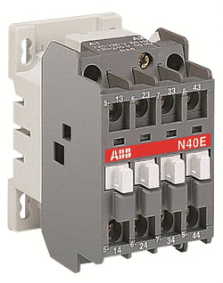
4-pole contactor relays , Control circuit AC operated with laminated magnet circuit - N40E 220-230V 50Hz / 230-240V 60Hz Contactor Relay
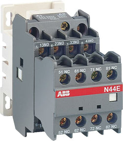
N44E 220-230V 50Hz / 230-240V 60Hz Contactor Relay

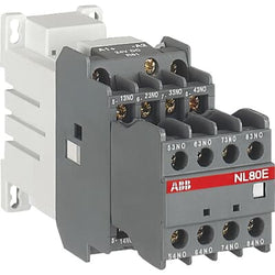
N80E 24V 50Hz / 24V 60Hz Contactor Relay

N22E 110V 50Hz / 110-120V 60Hz Contactor Relay

N31E 110V 50Hz / 110-120V 60Hz Contactor Relay

N40E 110V 50Hz / 110-120V 60Hz Contactor Relay

N44E 110V 50Hz / 110-120V 60Hz Contactor Relay

N62E 400-415V 50Hz / 415-440V 60Hz Contactor Relay

N22E 230-240V 50Hz / 240-260V 60Hz Contactor Relay
N31E 230-240V 50Hz / 240-260V 60Hz Contactor Relay

NL44E 220V DC Contactor Relay
NL62E 220V DC Contactor Relay

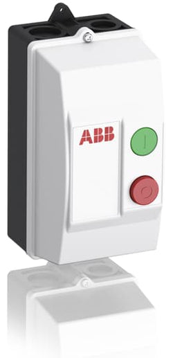
DRAS12-28P Contactor Starter
Ordering
1 piece
85364900
DRAF09
Popular Downloads
Dimensions
107 mm
131 mm
230 mm
0.82 kg
Technical
Holding at Max. Rated Control Circuit Voltage 60 Hz 250 V·A
Flexible with Ferrule 1/2x 0.75 ... 2.5 mm²
Flexible with Insulated Ferrule 1x 0.75 ... 2.5 mm²
Flexible with Insulated Ferrule 2x 0.75 ... 1.5 mm²
Rigid Solid 1/2x 1 ... 2.5 mm²
Rigid Stranded 1/2x 1 ... 2.5 mm²
Flexible with Ferrule 1/2x 0.75 ... 2.5 mm²
Flexible with Insulated Ferrule 1x 0.75 ... 2.5 mm²
Flexible with Insulated Ferrule 2x 0.75 ... 1.5 mm²
Rigid Solid 1/2x 1 ... 2.5 mm²
Rigid Stranded 1/2x 1 ... 2.5 mm²
Flexible with Ferrule 1/2x 0.75 ... 2.5 mm²
Flexible with Insulated Ferrule 1x 0.75 ... 2.5 mm²
Flexible with Insulated Ferrule 1x 0.75 ... 1.5 mm²
Rigid Solid 1/2x 1 ... 2.5 mm²
Rigid Stranded 1/2x 1 ... 2.5 mm²
Flexible with Ferrule 1/2x 0.75 ... 2.5 mm²
Flexible with Insulated Ferrule 1x 0.75 ... 2.5 mm²
Flexible with Insulated Ferrule 1x 0.75 ... 1.5 mm²
Rigid Solid 1/2x 1 ... 2.5 mm²
Rigid Stranded 1/2x 1 ... 2.5 mm²
Flexible with Ferrule 1/2x 0.75 ... 6 mm²
Flexible with Insulated Ferrule 1x 0.75 ... 4 mm²
Flexible with Insulated Ferrule 2x 0.75 ... 2.5 mm²
Rigid Solid 1/2x 1 ... 4 mm²
Rigid Stranded 1/2x 1 ... 6 mm²
Flexible with Ferrule 1/2x 0.75 ... 6 mm²
Flexible with Insulated Ferrule 1x 0.75 ... 4 mm²
Flexible with Insulated Ferrule 2x 0.75 ... 2.5 mm²
Rigid Solid 1/2x 1 ... 4 mm²
Rigid Stranded 1/2x 1 ... 6 mm²
ABS
0
1
0
3
3P
3
50 Hz 250 ... 500 V
60 Hz 250 ... 500 V
DC Operation 250 ... 500 V
50 Hz 250 ... 500 V
60 Hz 250 ... 500 V
DC Operation 250 ... 500 V
Auxiliary Circuit 50 / 60 Hz
Control Circuit 50 / 60 Hz
Main Circuit 50 / 60 Hz
Auxiliary Circuit 50 / 60 Hz
Control Circuit 50 / 60 Hz
Main Circuit 50 / 60 Hz
acc. to IEC 60947-4-1 690 V
acc. to IEC 60947-5-1 690 V
acc. to IEC 60947-4-1 690 V
acc. to IEC 60947-5-1 690 V
(690 V) 40 °C 25 A
(690 V) 60 °C 25 A
(690 V) 70 °C 22 A
(690 V) 40 °C 25 A
(690 V) 60 °C 25 A
(690 V) 70 °C 22 A
(415 V) 60 °C 9 A
(440 V) 60 °C 9 A
(500 V) 60 °C 9.5 A
(690 V) 60 °C 7 A
(380 / 400 V) 60 °C 9 A
(220 / 230 / 240 V) 60 °C 9 A
(415 V) 60 °C 9 A
(440 V) 60 °C 9 A
(500 V) 60 °C 9.5 A
(690 V) 60 °C 7 A
(380 / 400 V) 60 °C 9 A
(220 / 230 / 240 V) 60 °C 9 A
(415 V) 60 °C 9 A
(440 V) 60 °C 9 A
(500 V) 60 °C 9.5 A
(690 V) 60 °C 7 A
(380 / 400 V) 60 °C 9 A
(220 / 230 / 240 V) 60 °C 9 A
(415 V) 60 °C 9 A
(440 V) 60 °C 9 A
(500 V) 60 °C 9.5 A
(690 V) 60 °C 7 A
(380 / 400 V) 60 °C 9 A
(220 / 230 / 240 V) 60 °C 9 A
(415 V) 4 kW
(440 V) 4 kW
(500 V) 5.5 kW
(690 V) 5.5 kW
(380 / 400 V) 4 kW
(220 / 230 / 240 V) 2.2 kW
(415 V) 4 kW
(440 V) 4 kW
(500 V) 5.5 kW
(690 V) 5.5 kW
(380 / 400 V) 4 kW
(220 / 230 / 240 V) 2.2 kW
(415 V) 4 kW
(440 V) 4 kW
(500 V) 5.5 kW
(690 V) 5.5 kW
(380 / 400 V) 4 kW
(220 / 230 / 240 V) 2.2 kW
(415 V) 4 kW
(440 V) 4 kW
(500 V) 5.5 kW
(690 V) 5.5 kW
(380 / 400 V) 4 kW
(220 / 230 / 240 V) 2.2 kW
Screw Terminals
Technical UL/CSA
A600
Q600
A600
Q600
Material Compliance
Following EU Directive 2011/65/EU and Amendment 2015/863 July 22, 2019
Business To Business
5. Small Equipment (No External Dimension More Than 50 cm)
Certificates and Declarations
Container Information
box 1 piece
243 mm
112 mm
143 mm
0.82 kg
3471522144843
External Classifications and Standards
V11.0 : 27371205
3709751
EC000200 - Enclosure for control circuit devices
EC000200 - Enclosure for control circuit devices
EC000200 - Enclosure for control circuit devices
EC000200 - Enclosure for control circuit devices
4727 >> Motor starter controls
39121521

Ordering
1 piece
85364900
DRAF09
Popular Downloads
Dimensions
107 mm
131 mm
230 mm
0.82 kg
Technical
Holding at Max. Rated Control Circuit Voltage 60 Hz 100 V·A
Flexible with Ferrule 1/2x 0.75 ... 2.5 mm²
Flexible with Insulated Ferrule 1x 0.75 ... 2.5 mm²
Flexible with Insulated Ferrule 2x 0.75 ... 1.5 mm²
Rigid Solid 1/2x 1 ... 2.5 mm²
Rigid Stranded 1/2x 1 ... 2.5 mm²
Flexible with Ferrule 1/2x 0.75 ... 2.5 mm²
Flexible with Insulated Ferrule 1x 0.75 ... 2.5 mm²
Flexible with Insulated Ferrule 2x 0.75 ... 1.5 mm²
Rigid Solid 1/2x 1 ... 2.5 mm²
Rigid Stranded 1/2x 1 ... 2.5 mm²
Flexible with Ferrule 1/2x 0.75 ... 2.5 mm²
Flexible with Insulated Ferrule 1x 0.75 ... 2.5 mm²
Flexible with Insulated Ferrule 1x 0.75 ... 1.5 mm²
Rigid Solid 1/2x 1 ... 2.5 mm²
Rigid Stranded 1/2x 1 ... 2.5 mm²
Flexible with Ferrule 1/2x 0.75 ... 2.5 mm²
Flexible with Insulated Ferrule 1x 0.75 ... 2.5 mm²
Flexible with Insulated Ferrule 1x 0.75 ... 1.5 mm²
Rigid Solid 1/2x 1 ... 2.5 mm²
Rigid Stranded 1/2x 1 ... 2.5 mm²
Flexible with Ferrule 1/2x 0.75 ... 6 mm²
Flexible with Insulated Ferrule 1x 0.75 ... 4 mm²
Flexible with Insulated Ferrule 2x 0.75 ... 2.5 mm²
Rigid Solid 1/2x 1 ... 4 mm²
Rigid Stranded 1/2x 1 ... 6 mm²
Flexible with Ferrule 1/2x 0.75 ... 6 mm²
Flexible with Insulated Ferrule 1x 0.75 ... 4 mm²
Flexible with Insulated Ferrule 2x 0.75 ... 2.5 mm²
Rigid Solid 1/2x 1 ... 4 mm²
Rigid Stranded 1/2x 1 ... 6 mm²
ABS
0
1
0
3
3P
3
50 Hz 100 ... 250 V
60 Hz 100 ... 250 V
DC Operation 100 ... 250 V
50 Hz 100 ... 250 V
60 Hz 100 ... 250 V
DC Operation 100 ... 250 V
Auxiliary Circuit 50 / 60 Hz
Control Circuit 50 / 60 Hz
Main Circuit 50 / 60 Hz
Auxiliary Circuit 50 / 60 Hz
Control Circuit 50 / 60 Hz
Main Circuit 50 / 60 Hz
acc. to IEC 60947-4-1 690 V
acc. to IEC 60947-5-1 690 V
acc. to IEC 60947-4-1 690 V
acc. to IEC 60947-5-1 690 V
(690 V) 40 °C 25 A
(690 V) 60 °C 25 A
(690 V) 70 °C 22 A
(690 V) 40 °C 25 A
(690 V) 60 °C 25 A
(690 V) 70 °C 22 A
(415 V) 60 °C 9 A
(440 V) 60 °C 9 A
(500 V) 60 °C 9.5 A
(690 V) 60 °C 7 A
(380 / 400 V) 60 °C 9 A
(220 / 230 / 240 V) 60 °C 9 A
(415 V) 60 °C 9 A
(440 V) 60 °C 9 A
(500 V) 60 °C 9.5 A
(690 V) 60 °C 7 A
(380 / 400 V) 60 °C 9 A
(220 / 230 / 240 V) 60 °C 9 A
(415 V) 60 °C 9 A
(440 V) 60 °C 9 A
(500 V) 60 °C 9.5 A
(690 V) 60 °C 7 A
(380 / 400 V) 60 °C 9 A
(220 / 230 / 240 V) 60 °C 9 A
(415 V) 60 °C 9 A
(440 V) 60 °C 9 A
(500 V) 60 °C 9.5 A
(690 V) 60 °C 7 A
(380 / 400 V) 60 °C 9 A
(220 / 230 / 240 V) 60 °C 9 A
(415 V) 4 kW
(440 V) 4 kW
(500 V) 5.5 kW
(690 V) 5.5 kW
(380 / 400 V) 4 kW
(220 / 230 / 240 V) 2.2 kW
(415 V) 4 kW
(440 V) 4 kW
(500 V) 5.5 kW
(690 V) 5.5 kW
(380 / 400 V) 4 kW
(220 / 230 / 240 V) 2.2 kW
(415 V) 4 kW
(440 V) 4 kW
(500 V) 5.5 kW
(690 V) 5.5 kW
(380 / 400 V) 4 kW
(220 / 230 / 240 V) 2.2 kW
(415 V) 4 kW
(440 V) 4 kW
(500 V) 5.5 kW
(690 V) 5.5 kW
(380 / 400 V) 4 kW
(220 / 230 / 240 V) 2.2 kW
Screw Terminals
Technical UL/CSA
A600
Q600
A600
Q600
Material Compliance
Following EU Directive 2011/65/EU and Amendment 2015/863 July 22, 2019
Business To Business
5. Small Equipment (No External Dimension More Than 50 cm)
Certificates and Declarations
Container Information
box 1 piece
243 mm
112 mm
143 mm
0.82 kg
3471522144539
External Classifications and Standards
V11.0 : 27371205
3709762
EC000200 - Enclosure for control circuit devices
EC000200 - Enclosure for control circuit devices
EC000200 - Enclosure for control circuit devices
EC000200 - Enclosure for control circuit devices
4727 >> Motor starter controls
39121521

Ordering
1 piece
85364900
DRAF12
Popular Downloads
Dimensions
107 mm
131 mm
230 mm
0.82 kg
Technical
Holding at Max. Rated Control Circuit Voltage 60 Hz 250 V·A
Flexible with Ferrule 1/2x 0.75 ... 2.5 mm²
Flexible with Insulated Ferrule 1x 0.75 ... 2.5 mm²
Flexible with Insulated Ferrule 2x 0.75 ... 1.5 mm²
Rigid Solid 1/2x 1 ... 2.5 mm²
Rigid Stranded 1/2x 1 ... 2.5 mm²
Flexible with Ferrule 1/2x 0.75 ... 2.5 mm²
Flexible with Insulated Ferrule 1x 0.75 ... 2.5 mm²
Flexible with Insulated Ferrule 2x 0.75 ... 1.5 mm²
Rigid Solid 1/2x 1 ... 2.5 mm²
Rigid Stranded 1/2x 1 ... 2.5 mm²
Flexible with Ferrule 1/2x 0.75 ... 2.5 mm²
Flexible with Insulated Ferrule 1x 0.75 ... 2.5 mm²
Flexible with Insulated Ferrule 1x 0.75 ... 1.5 mm²
Rigid Solid 1/2x 1 ... 2.5 mm²
Rigid Stranded 1/2x 1 ... 2.5 mm²
Flexible with Ferrule 1/2x 0.75 ... 2.5 mm²
Flexible with Insulated Ferrule 1x 0.75 ... 2.5 mm²
Flexible with Insulated Ferrule 1x 0.75 ... 1.5 mm²
Rigid Solid 1/2x 1 ... 2.5 mm²
Rigid Stranded 1/2x 1 ... 2.5 mm²
Flexible with Ferrule 1/2x 0.75 ... 6 mm²
Flexible with Insulated Ferrule 1x 0.75 ... 4 mm²
Flexible with Insulated Ferrule 2x 0.75 ... 2.5 mm²
Rigid Solid 1/2x 1 ... 4 mm²
Rigid Stranded 1/2x 1 ... 6 mm²
Flexible with Ferrule 1/2x 0.75 ... 6 mm²
Flexible with Insulated Ferrule 1x 0.75 ... 4 mm²
Flexible with Insulated Ferrule 2x 0.75 ... 2.5 mm²
Rigid Solid 1/2x 1 ... 4 mm²
Rigid Stranded 1/2x 1 ... 6 mm²
ABS
0
1
0
3
3P
3
50 Hz 250 ... 500 V
60 Hz 250 ... 500 V
DC Operation 250 ... 500 V
50 Hz 250 ... 500 V
60 Hz 250 ... 500 V
DC Operation 250 ... 500 V
Auxiliary Circuit 50 / 60 Hz
Control Circuit 50 / 60 Hz
Main Circuit 50 / 60 Hz
Auxiliary Circuit 50 / 60 Hz
Control Circuit 50 / 60 Hz
Main Circuit 50 / 60 Hz
acc. to IEC 60947-4-1 690 V
acc. to IEC 60947-5-1 690 V
acc. to IEC 60947-4-1 690 V
acc. to IEC 60947-5-1 690 V
(690 V) 40 °C 28 A
(690 V) 60 °C 28 A
(690 V) 70 °C 24 A
(690 V) 40 °C 28 A
(690 V) 60 °C 28 A
(690 V) 70 °C 24 A
(415 V) 60 °C 12 A
(440 V) 60 °C 12 A
(500 V) 60 °C 12.5 A
(690 V) 60 °C 9 A
(380 / 400 V) 60 °C 12 A
(220 / 230 / 240 V) 60 °C 12 A
(415 V) 60 °C 12 A
(440 V) 60 °C 12 A
(500 V) 60 °C 12.5 A
(690 V) 60 °C 9 A
(380 / 400 V) 60 °C 12 A
(220 / 230 / 240 V) 60 °C 12 A
(415 V) 60 °C 12 A
(440 V) 60 °C 12 A
(500 V) 60 °C 12.5 A
(690 V) 60 °C 9 A
(380 / 400 V) 60 °C 12 A
(220 / 230 / 240 V) 60 °C 12 A
(415 V) 60 °C 12 A
(440 V) 60 °C 12 A
(500 V) 60 °C 12.5 A
(690 V) 60 °C 9 A
(380 / 400 V) 60 °C 12 A
(220 / 230 / 240 V) 60 °C 12 A
(415 V) 5.5 kW
(440 V) 5.5 kW
(500 V) 7.5 kW
(690 V) 7.5 kW
(380 / 400 V) 5.5 kW
(220 / 230 / 240 V) 3 kW
(415 V) 5.5 kW
(440 V) 5.5 kW
(500 V) 7.5 kW
(690 V) 7.5 kW
(380 / 400 V) 5.5 kW
(220 / 230 / 240 V) 3 kW
(415 V) 5.5 kW
(440 V) 5.5 kW
(500 V) 7.5 kW
(690 V) 7.5 kW
(380 / 400 V) 5.5 kW
(220 / 230 / 240 V) 3 kW
(415 V) 5.5 kW
(440 V) 5.5 kW
(500 V) 7.5 kW
(690 V) 7.5 kW
(380 / 400 V) 5.5 kW
(220 / 230 / 240 V) 3 kW
Screw Terminals
Technical UL/CSA
Rigid Solid 1/2x 18-14 AWG
Rigid Stranded 1/2x 18-14 AWG
Rigid Solid 1/2x 18-14 AWG
Rigid Stranded 1/2x 18-14 AWG
Rigid Solid 1/2x 18-14 AWG
Rigid Stranded 1/2x 18-14 AWG
Rigid Solid 1/2x 18-14 AWG
Rigid Stranded 1/2x 18-14 AWG
Rigid Solid 1/2x 16-10 AWG
Rigid Stranded 1/2x 16-10 AWG
Rigid Solid 1/2x 16-10 AWG
Rigid Stranded 1/2x 16-10 AWG
(115 V AC) Single Phase 1 Hp
(200 V AC) Three Phase 3 Hp
(230 V AC) Single Phase 2 Hp
(230 V AC) Three Phase 3 Hp
(460 V AC) Three Phase 5 Hp
(575 V AC) Three Phase 5 Hp
(115 V AC) Single Phase 1 Hp
(200 V AC) Three Phase 3 Hp
(230 V AC) Single Phase 2 Hp
(230 V AC) Three Phase 3 Hp
(460 V AC) Three Phase 5 Hp
(575 V AC) Three Phase 5 Hp
(120 V AC) Single Phase 1 Hp
(200 ... 208 V AC) Three Phase 3 Hp
(220 ... 240 V AC) Three Phase 3 Hp
(240 V AC) Single Phase 2 Hp
(440 ... 480 V AC) Three Phase 7.5 Hp
(550 ... 600 V AC) Three Phase 10 Hp
(120 V AC) Single Phase 1 Hp
(200 ... 208 V AC) Three Phase 3 Hp
(220 ... 240 V AC) Three Phase 3 Hp
(240 V AC) Single Phase 2 Hp
(440 ... 480 V AC) Three Phase 7.5 Hp
(550 ... 600 V AC) Three Phase 10 Hp
A600
Q600
A600
Q600
Material Compliance
Following EU Directive 2011/65/EU and Amendment 2015/863 July 22, 2019
Business To Business
5. Small Equipment (No External Dimension More Than 50 cm)
Certificates and Declarations
Container Information
box 1 piece
243 mm
112 mm
143 mm
0.82 kg
3471522145246
External Classifications and Standards
V11.0 : 27371205
3709772
EC000200 - Enclosure for control circuit devices
EC000200 - Enclosure for control circuit devices
EC000200 - Enclosure for control circuit devices
EC000200 - Enclosure for control circuit devices
4727 >> Motor starter controls
39121521
Ordering
1 piece
85364900
Popular Downloads
Dimensions
45 mm
72.5 mm
68 mm
0.22 kg
Technical
3
0
0
1
IEC 60947-1 / 60947-4-1 and EN 60947-1 / 60947-4-1, UL 508, CSA C22.2 N°14
Auxiliary Circuit 690 V
Main Circuit 690 V
Auxiliary Circuit 690 V
Main Circuit 690 V
Auxiliary Circuit 50 / 60 Hz
Main Circuit 50 / 60 Hz
Auxiliary Circuit 50 / 60 Hz
Main Circuit 50 / 60 Hz
acc. to IEC 60947-4-1, Open Contactors Θ = 40 °C 22 A
acc. to IEC 60947-5-1, Θ = 40 °C 10 A
acc. to IEC 60947-4-1, Open Contactors Θ = 40 °C 22 A
acc. to IEC 60947-5-1, Θ = 40 °C 10 A
(690 V) 40 °C 22 A
(690 V) 60 °C 18 A
(690 V) 70 °C 15 A
(690 V) 40 °C 22 A
(690 V) 60 °C 18 A
(690 V) 70 °C 15 A
(415 V) 60 °C 9 A
(440 V) 60 °C 8 A
(500 V) 60 °C 8 A
(690 V) 60 °C 5 A
(380 / 400 V) 60 °C 9 A
(220 / 230 / 240 V) 60 °C 9 A
(415 V) 60 °C 9 A
(440 V) 60 °C 8 A
(500 V) 60 °C 8 A
(690 V) 60 °C 5 A
(380 / 400 V) 60 °C 9 A
(220 / 230 / 240 V) 60 °C 9 A
(500 V) NC 2
(500 V) 2 A
(690 V) 2 A
(24 / 127 V) 6 A
(220 / 240 V) 4 A
(400 / 440 V) 3 A
(500 V) NC 2
(500 V) 2 A
(690 V) 2 A
(24 / 127 V) 6 A
(220 / 240 V) 4 A
(400 / 440 V) 3 A
(24 V) 6 A / 144 W
(48 V) 2.8 A / 134 W
(72 V) 1 A / 72 W
(110 V) 0.55 A / 60 W
(125 V) 0.55 A / 69 W
(220 V) 0.27 A / 60 W
(250 V) 0.27 A / 68 W
(24 V) 6 A / 144 W
(48 V) 2.8 A / 134 W
(72 V) 1 A / 72 W
(110 V) 0.55 A / 60 W
(125 V) 0.55 A / 69 W
(220 V) 0.27 A / 60 W
(250 V) 0.27 A / 68 W
(400 V) 4 kW
(415 V) 4 kW
(440 V) 4 kW
(500 V) 4 kW
(690 V) 4 kW
(220 / 230 / 240 V) 2.2 kW
(400 V) 4 kW
(415 V) 4 kW
(440 V) 4 kW
(500 V) 4 kW
(690 V) 4 kW
(220 / 230 / 240 V) 2.2 kW
at 40 °C Ambient Temp, in Free Air, from a Cold State 10 s 100 A
at 40 °C Ambient Temp, in Free Air, from a Cold State 15 min 22 A
at 40 °C Ambient Temp, in Free Air, from a Cold State 1 min 50 A
at 40 °C Ambient Temp, in Free Air, from a Cold State 1 s 230 A
at 40 °C Ambient Temp, in Free Air, from a Cold State 30 s 65 A
for 0.1 s 140 A
for 1 s 100 A
cos phi=0.45 (cos phi=0.35 for Ie > 100 A) at 440 V 155 A
cos phi=0.45 (cos phi=0.35 for Ie > 100 A) at 690 V 90 A
cos phi=0.45 (cos phi=0.35 for Ie > 100 A) at 440 V 155 A
cos phi=0.45 (cos phi=0.35 for Ie > 100 A) at 690 V 90 A
acc. to IEC 60947-4-1 and VDE 0110 (Gr. C) 690 V
acc. to IEC 60947-5-1 and VDE 0110 (Gr. C) 690 V
acc. to UL/CSA 600 V
acc. to IEC 60947-4-1 and VDE 0110 (Gr. C) 690 V
acc. to IEC 60947-5-1 and VDE 0110 (Gr. C) 690 V
acc. to UL/CSA 600 V
Auxiliary Circuit 6 kV
(AC-1) 600 cycles per hour
(AC-15) 1200 cycles per hour
(AC-2 / AC-4) 300 cycles per hour
(AC-3) 1200 cycles per hour
(DC-13) 900 cycles per hour
(AC-1) 600 cycles per hour
(AC-15) 1200 cycles per hour
(AC-2 / AC-4) 300 cycles per hour
(AC-3) 1200 cycles per hour
(DC-13) 900 cycles per hour
3600 cycles per hour
50 Hz 24 V
60 Hz 24 V
50 Hz 24 V
60 Hz 24 V
at Rated Operating Conditions AC-1 per Pole 1 W
at Rated Operating Conditions AC-3 per Pole 0.16 W
at Rated Operating Conditions AC-1 per Pole 1 W
at Rated Operating Conditions AC-3 per Pole 0.16 W
Between Coil De-energization and NC Contact Closing 7 ... 22 ms
Between Coil De-energization and NO Contact Opening 5 ... 19 ms
Between Coil Energization and NC Contact Opening 6 ... 18 ms
Between Coil Energization and NO Contact Closing 9 ... 24 ms
Between Coil De-energization and NC Contact Closing 7 ... 22 ms
Between Coil De-energization and NO Contact Opening 5 ... 19 ms
Between Coil Energization and NC Contact Opening 6 ... 18 ms
Between Coil Energization and NO Contact Closing 9 ... 24 ms
Flexible with Ferrule 1/2x 0.75 ... 2.5 mm²
Flexible with Insulated Ferrule 1x 0.75 ... 2.5 mm²
Flexible with Insulated Ferrule 2x 0.75 ... 1.5 mm²
Rigid 1/2x 0.75 ... 4 mm²
Flexible with Ferrule 1/2x 0.75 ... 2.5 mm²
Flexible with Insulated Ferrule 1x 0.75 ... 2.5 mm²
Flexible with Insulated Ferrule 2x 0.75 ... 1.5 mm²
Rigid 1/2x 0.75 ... 4 mm²
Flexible with Ferrule 1/2x 0.75 ... 2.5 mm²
Flexible with Insulated Ferrule 1x 0.75 ... 2.5 mm²
Flexible with Insulated Ferrule 2x 0.75 ... 1.5 mm²
Rigid 1/2x 0.75 ... 2.5 mm²
Flexible with Ferrule 1/2x 0.75 ... 2.5 mm²
Flexible with Insulated Ferrule 1x 0.75 ... 2.5 mm²
Flexible with Insulated Ferrule 2x 0.75 ... 1.5 mm²
Rigid 1/2x 0.75 ... 2.5 mm²
Flexible with Ferrule 1/2x 0.75 ... 2.5 mm²
Flexible with Insulated Ferrule 1x 0.75 ... 2.5 mm²
Flexible with Insulated Ferrule 2x 0.75 ... 1.5 mm²
Rigid 1/2x 0.75 ... 2.5 mm²
Flexible with Ferrule 1/2x 0.75 ... 2.5 mm²
Flexible with Insulated Ferrule 1x 0.75 ... 2.5 mm²
Flexible with Insulated Ferrule 2x 0.75 ... 1.5 mm²
Rigid 1/2x 0.75 ... 2.5 mm²
Auxiliary Circuit 9 mm
Control Circuit 9 mm
Main Circuit 9 mm
Auxiliary Circuit 9 mm
Control Circuit 9 mm
Main Circuit 9 mm
acc. to IEC 60529, IEC 60947-1, EN 60529 Auxiliary Terminals IP20
acc. to IEC 60529, IEC 60947-1, EN 60529 Coil Terminals IP20
acc. to IEC 60529, IEC 60947-1, EN 60529 Main Terminals IP20
acc. to IEC 60529, IEC 60947-1, EN 60529 Auxiliary Terminals IP20
acc. to IEC 60529, IEC 60947-1, EN 60529 Coil Terminals IP20
acc. to IEC 60529, IEC 60947-1, EN 60529 Main Terminals IP20
Auxiliary Circuit 1 N·m
Control Circuit 1 N·m
Main Circuit 1 N·m
Auxiliary Circuit 1 N·m
Control Circuit 1 N·m
Main Circuit 1 N·m
Screw Terminals
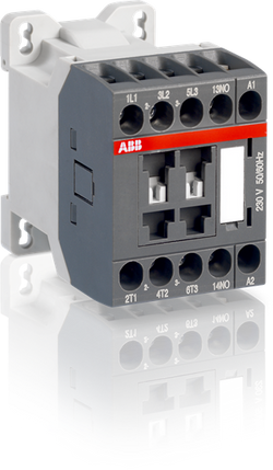
Block Contactor
Technical UL/CSA
(600 V AC) 20 A
(120 V AC) Single Phase 1/3 hp
(200 ... 208 V AC) Three Phase 2 hp
(220 ... 240 V AC) Three Phase 2 hp
(240 V AC) Single Phase 1 hp
(440 ... 480 V AC) Three Phase 5 hp
(550 ... 600 V AC) Three Phase 7.5 hp
(120 V AC) Single Phase 1/3 hp
(200 ... 208 V AC) Three Phase 2 hp
(220 ... 240 V AC) Three Phase 2 hp
(240 V AC) Single Phase 1 hp
(440 ... 480 V AC) Three Phase 5 hp
(550 ... 600 V AC) Three Phase 7.5 hp
Auxiliary Circuit 9 in·lb
Control Circuit 9 in·lb
Main Circuit 9 in·lb
Auxiliary Circuit 9 in·lb
Control Circuit 9 in·lb
Main Circuit 9 in·lb
(120 V AC) Single Phase 7.2 A
(200 ... 208 V AC) Three Phase 7.8 A
(220 ... 240 V AC) Three Phase 6.8 A
(240 V AC) Single Phase 8 A
(440 ... 480 V AC) Three Phase 7.6 A
(550 ... 600 V AC) Three Phase 9 A
(120 V AC) Single Phase 7.2 A
(200 ... 208 V AC) Three Phase 7.8 A
(220 ... 240 V AC) Three Phase 6.8 A
(240 V AC) Single Phase 8 A
(440 ... 480 V AC) Three Phase 7.6 A
(550 ... 600 V AC) Three Phase 9 A
Environmental
Close to Contactor Fitted with Thermal O/L Relay -25 ... 60 °C
Close to Contactor without Thermal O/L Relay -40 ... 70 °C
Close to Contactor for Storage -60 ... +80 °C
Close to Contactor Fitted with Thermal O/L Relay -25 ... 60 °C
Close to Contactor without Thermal O/L Relay -40 ... 70 °C
Close to Contactor for Storage -60 ... +80 °C
Category B according to IEC 60947-1 Annex Q
Without Derating 3000 m
Closed, Shock Direction: B1 10 g
Closed, Shock Direction: C1 20 g
Closed, Shock Direction: C2 20 g
Open, Shock Direction: B1 5 g
Open, Shock Direction: C1 9 g
Open, Shock Direction: C2 14 g
Shock Direction: A 20 g
Shock Direction: B2 15 g
Closed, Shock Direction: B1 10 g
Closed, Shock Direction: C1 20 g
Closed, Shock Direction: C2 20 g
Open, Shock Direction: B1 5 g
Open, Shock Direction: C1 9 g
Open, Shock Direction: C2 14 g
Shock Direction: A 20 g
Shock Direction: B2 15 g
3g Closed Position & 2g Open Position 5 ... 300 Hz
Material Compliance
Following EU Directive 2011/65/EU and Amendment 2015/863 July 22, 2019
Business To Business
5. Small Equipment (No External Dimension More Than 50 cm)
Certificates and Declarations
Container Information
box 1 piece
78 mm
80 mm
48 mm
0.22 kg
3471523033207
960 piece
External Classifications and Standards
Q
EC000066 - Power contactor, AC switching
EC000066 - Power contactor, AC switching
EC000066 - Power contactor, AC switching
V11.0 : 27371003
39121529
4761 >> Magnet contactor, AC-switching
3210505