
 1 year warranty


TeSys GV5 - long terminal shields IP40
EasyPact TVS contactor 3P(3 NO) - AC-3 - = 440 V 32A - 110 V AC coil
TeSys K contactor - 3P - AC-3 <= 440 V 6 A - 1 NC aux. - 230 V AC coil
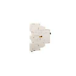
TeSys GV auxiliary contact block, for motor circuit breakers GV2 and GV3. 1C/O contact for short circuit signaling. Rated for operation up to 2A/240V AC and 1A/60V DC. To be installed on left-hand side of the circuit breaker (1 block mounting maximum), connection by screw clamp terminals. Multi standards certified (IEC, UL, CSA, CCC, EAC).
Main
| Characteristic | Value(s) |
|---|---|
| Range | TeSys TeSys Deca |
| Device short name | GVAM |
| Product or Component Type | Auxiliary contact block |
| Product Compatibility | GV2L GV2ME GV2RT GV3L GV2P GV3P GV2LE |
| Mounting Location | Left side |
| Auxiliary contacts operation | Short-circuit signal 1 C/O |
| Pole contact composition | 1 C/O |
Complementary
| Characteristic | Value(s) |
|---|---|
| [Ui] rated insulation voltage | 690 V IEC 60947-1 300 V UL 508 300 V CSA C22.2 No 14 |
| [Ue] rated operational voltage | 24...240 V AC 24...60 V DC |
| [Ith] conventional free air thermal current | 2.5 A for fault signalling |
| Mechanical durability | 100000 cycles |
| Minimum switching current | 5 mA |
| Minimum switching voltage | 17 V |
| Protection type | GB2CB... circuit breaker GG fuse 10 A |
| Rated operational power in VA | 36 VA 24 V AC-14 1000 cycles 1.5 A 48 VA 48 V AC-14 1000 cycles 1 A 72 VA 110â¦127 V AC-14 1000 cycles 0.5 A 72 VA 230â¦240 V AC-14 1000 cycles 0.3 A |
| Rated operational power in W | 120 W 240 V DC-13 100000 cycles 140 W 110 V DC-13 100000 cycles 140 W 24 V DC-13 100000 cycles 180 W 60 V DC-13 100000 cycles 240 W 48 V DC-13 100000 cycles 15 W 48 V DC-13 1000 cycles 24 W 24 V DC-13 1000 cycles 9 W 60 V DC-13 1000 cycles |
| Tightening torque | 12.4 lbf.in (1.4 N.m) screw clamp terminals |
| Height | 3.5 in (89 mm) |
| Width | 0.4 in (9.3 mm) |
| Depth | 2.6 in (66 mm) |
| Product Weight | 0.121 lb(US) (0.055 kg) |
| color | Dark grey |

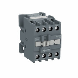
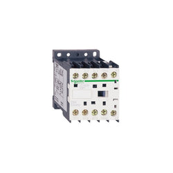
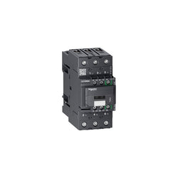
LC1K1210E7 is a compact 3-pole TeSys K contactor from Schneider Electric for motor applications. Rated 12A AC-3 5.5kW@400V, it includes a 48V 50/60Hz AC coil and 1NO auxiliary contact. LC1K1210E7 is a 3-pole TeSys K contactor from Schneider Electric for simple motor applications rated up to 5.5kW@400V. Very compact, DIN-rail compatible, with connections by screw clamp terminals, it includes a 40V 50/60Hz AC coil and 1NO built-in auxiliary contact. Available worldwide, it complies with multi-standards (IEC, UL, CSA, CCC, EAC, Marine). Very compact, 45mm wide, for DIN-rail and panel mounting. Provides a control circuit compatible with 50Hz and 60Hz supplies and 1NO built-in auxiliary contact. Optimized for simple power applications. Can be completed with auxiliary contact blocks (LA1K, LA2K) and thermal relays (LR2K).
Main
| Characteristic | Value(s) |
|---|---|
| Range | TeSys |
| Product or Component Type | Contactor |
| Device short name | LC1K |
| Device Application | Control |
| Contactor application | Resistive load Motor control |
Complementary
| Characteristic | Value(s) |
|---|---|
| Utilisation category | AC-3 AC-3e AC-1 AC-4 |
| Poles description | 3P |
| power pole contact composition | 3 NO |
| [Ue] rated operational voltage | Power circuit <= 690 V AC <= 400 Hz Signalling circuit <= 690 V AC <= 400 Hz |
| [Ie] rated operational current | 12 A (at <140 °F (60 °C)) at <= 440 V AC AC-3 for power circuit 12 A (at <140 °F (60 °C)) at <= 440 V AC AC-3e for power circuit 20 A (at <140 °F (60 °C)) at <= 690 V AC AC-1 for power circuit |
| Control circuit type | AC 50/60 Hz |
| [Uc] control circuit voltage | 48 V AC 50/60 Hz |
| Motor power kW | 3 kW 220...230 V AC 50/60 Hz AC-3 5.5 kW 380...415 V AC 50/60 Hz AC-3 5.5 kW 440 V AC 50/60 Hz AC-3 4 kW 690 V AC 50/60 Hz AC-3 3 kW 220...230 V AC 50/60 Hz AC-3e 5.5 kW 380...415 V AC 50/60 Hz AC-3e 5.5 kW 440 V AC 50/60 Hz AC-3e 4 kW 690 V AC 50/60 Hz AC-3e 3 kW 220...230 V AC 50/60 Hz AC-4 5.5 kW 380...415 V AC 50/60 Hz AC-4 5.5 kW 440 V AC 50/60 Hz AC-4 4 kW 690 V AC 50/60 Hz AC-4 |
| Auxiliary contact composition | 1 NO |
| [Uimp] rated impulse withstand voltage | 8 kV |
| Overvoltage category | III |
| [Ith] conventional free air thermal current | 20 A (at 140 °F (60 °C)) for power circuit 10 A (at 122 °F (50 °C)) for signalling circuit |
| Irms rated making capacity | 144 A AC for power circuit conforming to IEC 60947 110 A AC for signalling circuit conforming to IEC 60947 |
| Rated breaking capacity | 110 A at 440 V conforming to IEC 60947 80 A at 500 V conforming to IEC 60947 70 A at 660...690 V conforming to IEC 60947 |
| [Icw] rated short-time withstand current | 115 A 122 °F (50 °C) - 1 s for power circuit 105 A 122 °F (50 °C) - 5 s for power circuit 100 A 122 °F (50 °C) - 10 s for power circuit 75 A 122 °F (50 °C) - 30 s for power circuit 55 A 122 °F (50 °C) - 1 min for power circuit 50 A 122 °F (50 °C) - 3 min for power circuit 25 A 122 °F (50 °C) - >= 15 min for power circuit 80 A - 1 s for signalling circuit 90 A - 500 ms for signalling circuit 110 A - 100 ms for signalling circuit |
| Associated fuse rating | 25 A gG at <= 440 V for power circuit 25 A aM for power circuit 10 A gG for signalling circuit conforming to IEC 60947 10 A gG for signalling circuit conforming to VDE 0660 |
| Average impedance | 3 mOhm - Ith 20 A 50 Hz for power circuit |
| [Ui] rated insulation voltage | Power circuit 600 V UL 508 Power circuit 690 V IEC 60947-4-1 Signalling circuit 690 V IEC 60947-4-1 Signalling circuit 690 V IEC 60947-5-1 Signalling circuit 600 V UL 508 Power circuit 600 V CSA C22.2 No 14 Signalling circuit 600 V CSA C22.2 No 14 |
| Insulation resistance | > 10 MOhm for signalling circuit |
| Inrush power in VA | 30 VA (at 68 °F (20 °C)) |
| Hold-in power consumption in VA | 4.5 VA (at 68 °F (20 °C)) |
| Heat dissipation | 1.3 W |
| Control circuit voltage limits | Operational: 0.8...1.15 Uc (at <122 °F (50 °C)) Drop-out: >= 0.20 Uc (at <122 °F (50 °C)) |
| Connections - terminals | screw clamp terminals 1 0.002â¦0.006 in² (1.5â¦4 mm²)solid screw clamp terminals 1 0.001â¦0.006 in² (0.75â¦4 mm²)flexible without cable end screw clamp terminals 1 0.0005â¦0.004 in² (0.34â¦2.5 mm²)flexible with cable end screw clamp terminals 2 0.002â¦0.006 in² (1.5â¦4 mm²)solid screw clamp terminals 2 0.001â¦0.006 in² (0.75â¦4 mm²)flexible without cable end screw clamp terminals 2 0.0005â¦0.002 in² (0.34â¦1.5 mm²)flexible with cable end |
| Maximum operating rate | 3600 cyc/h |
| Auxiliary contacts type | Instantaneous 1 NO |
| Signalling circuit frequency | <= 400 Hz |
| Minimum switching current | 5 mA for signalling circuit |
| Minimum switching voltage | 17 V for signalling circuit |
| Mounting Support | Plate Rail |
| Tightening torque | 7.08â¦11.5 lbf.in (0.8â¦1.3 N.m) screw clamp terminals Philips No 2 7.08â¦11.5 lbf.in (0.8â¦1.3 N.m) screw clamp terminals flat à 6 mm 7.08â¦11.5 lbf.in (0.8â¦1.3 N.m) screw clamp terminals pozidriv No 2 |
| Operating time | 10...20 ms coil de-energisation and NO opening 10...20 ms coil energisation and NO closing |
| Safety reliability level | B10d = 1369863 cycles contactor with nominal load EN/ISO 13849-1 B10d = 20000000 cycles contactor with mechanical load EN/ISO 13849-1 |
| Non overlap distance | 0.02 in (0.5 mm) |
| Mechanical durability | 10 Mcycles |
| Electrical durability | 1.3 Mcycles 12 A AC-3 <= 440 V 1.3 Mcycles 12 A AC-3e <= 440 V 0.3 Mcycles 20 A AC-1 <= 690 V 0.02 Mcycles 72 A AC-4 <= 440 V |
| Mechanical robustness | Shocks contactor closed, on X axis10 Gn for 11 ms IEC 60068-2-27 Shocks contactor closed, on Y axis15 Gn for 11 ms IEC 60068-2-27 Shocks contactor closed, on Z axis15 Gn for 11 ms IEC 60068-2-27 Shocks contactor opened, on X axis6 Gn for 11 ms IEC 60068-2-27 Shocks contactor opened, on Y axis10 Gn for 11 ms IEC 60068-2-27 Shocks contactor opened, on Z axis10 Gn for 11 ms IEC 60068-2-27 Vibrations contactor closed4 Gn, 5...300 Hz IEC 60068-2-6 Vibrations contactor opened2 Gn, 5...300 Hz IEC 60068-2-6 |
| Height | 2.3 in (58 mm) |
| Width | 1.8 in (45 mm) |
| Depth | 2.2 in (57 mm) |
| Product Weight | 0.40 lb(US) (0.18 kg) |
Main
| Characteristic | Value(s) |
|---|---|
| Range | TeSys |
| Range of Product | TeSys Deca |
| Product or Component Type | Contactor |
| Device short name | LC1D |
| Contactor application | Resistive load |
| Utilisation category | AC-1 |
| Poles description | 4P |
| [Ue] rated operational voltage | Power circuit <= 690 V AC 25...400 Hz Power circuit <= 300 V DC |
| [Ie] rated operational current | 80 A (at <140 °F (60 °C)) at <= 440 V AC AC-1 for power circuit |
| [Uc] control circuit voltage | 440 V DC |
Complementary
| Characteristic | Value(s) |
|---|---|
| Compatibility code | LC1D |
| Pole contact composition | 4 NO |
| Protective cover | With |
| [Ith] conventional free air thermal current | 10 A (at 140 °F (60 °C)) for signalling circuit 80 A (at 140 °F (60 °C)) for power circuit |
| Irms rated making capacity | 140 A AC for signalling circuit conforming to IEC 60947-5-1 250 A DC for signalling circuit conforming to IEC 60947-5-1 1000 A at 440 V for power circuit conforming to IEC 60947 |
| Rated breaking capacity | 1000 A at 440 V for power circuit conforming to IEC 60947 |
| [Icw] rated short-time withstand current | 520 A 104 °F (40 °C) - 10 s for power circuit 900 A 104 °F (40 °C) - 1 s for power circuit 110 A 104 °F (40 °C) - 10 min for power circuit 260 A 104 °F (40 °C) - 1 min for power circuit 100 A - 1 s for signalling circuit 120 A - 500 ms for signalling circuit 140 A - 100 ms for signalling circuit |
| Associated fuse rating | 10 A gG for signalling circuit conforming to IEC 60947-5-1 125 A gG at <= 690 V coordination type 1 for power circuit 125 A gG at <= 690 V coordination type 2 for power circuit |
| Average impedance | 1.6 mOhm - Ith 80 A 50 Hz for power circuit |
| Power dissipation per pole | 10.2 W AC-1 |
| [Ui] rated insulation voltage | Power circuit 600 V CSA Power circuit 600 V UL Signalling circuit 690 V IEC 60947-1 Signalling circuit 600 V CSA Signalling circuit 600 V UL Power circuit 690 V IEC 60947-4-1 |
| Overvoltage category | III |
| pollution degree | 3 |
| [Uimp] rated impulse withstand voltage | 6 kV IEC 60947 |
| Safety reliability level | B10d = 1369863 cycles contactor with nominal load EN/ISO 13849-1 B10d = 20000000 cycles contactor with mechanical load EN/ISO 13849-1 |
| Mechanical durability | 10 Mcycles |
| Electrical durability | 0.5 Mcycles 80 A AC-1 <= 440 V |
| Control circuit type | DC standard |
| Coil technology | Built-in bidirectional peak limiting diode suppressor |
| Control circuit voltage limits | 0.1...0.3 Uc (-40â¦158 °F (-40â¦70 °C)):drop-out DC 0.75...1.25 Uc (-40â¦140 °F (-40â¦60 °C)):operational DC 1...1.25 Uc (140â¦158 °F (60â¦70 °C)):operational DC |
| Inrush power in W | 19 W 68 °F (20 °C)) |
| Hold-in power consumption in W | 7.4 W 68 °F (20 °C) |
| Operating time | 42.5...57.5 ms closing 16...24 ms opening |
| Time constant | 34 ms |
| Connections - terminals | Control circuit: screw clamp terminals 2 0.002â¦0.004 in² (1â¦2.5 mm²) - cable stiffness: flexible with cable end Control circuit: screw clamp terminals 1 0.002â¦0.006 in² (1â¦4 mm²) - cable stiffness: flexible without cable end Control circuit: screw clamp terminals 2 0.002â¦0.006 in² (1â¦4 mm²) - cable stiffness: flexible without cable end Control circuit: screw clamp terminals 1 0.002â¦0.006 in² (1â¦4 mm²) - cable stiffness: flexible with cable end Control circuit: screw clamp terminals 1 0.002â¦0.006 in² (1â¦4 mm²) - cable stiffness: solid without cable end Control circuit: screw clamp terminals 2 0.002â¦0.006 in² (1â¦4 mm²) - cable stiffness: solid without cable end Power circuit: EverLink BTR screw connectors 1 0.002â¦0.05 in² (1â¦35 mm²) - cable stiffness: flexible without cable end Power circuit: EverLink BTR screw connectors 2 0.002â¦0.04 in² (1â¦25 mm²) - cable stiffness: flexible without cable end Power circuit: EverLink BTR screw connectors 1 0.002â¦0.05 in² (1â¦35 mm²) - cable stiffness: flexible with cable end Power circuit: EverLink BTR screw connectors 2 0.002â¦0.04 in² (1â¦25 mm²) - cable stiffness: flexible with cable end Power circuit: EverLink BTR screw connectors 1 0.002â¦0.05 in² (1â¦35 mm²) - cable stiffness: solid without cable end Power circuit: EverLink BTR screw connectors 2 0.002â¦0.04 in² (1â¦25 mm²) - cable stiffness: solid without cable end |
| Tightening torque | Control circuit 15.05 lbf.in (1.7 N.m) screw clamp terminals flat à 6 mm Control circuit 15.05 lbf.in (1.7 N.m) screw clamp terminals Philips No 2 Power circuit 70.8 lbf.in (8 N.m) screw clamp terminals 0.04â¦0.05 in² (25â¦35 mm²) hexagonal 0.2 in (4 mm) Power circuit 44.3 lbf.in (5 N.m) screw clamp terminals 0.002â¦0.04 in² (1â¦25 mm²) hexagonal 0.2 in (4 mm) |
| Auxiliary contact composition | 1 NO + 1 NC |
| Auxiliary contacts type | Mechanically linked 1 NO + 1 NC IEC 60947-5-1 Mirror contact 1 NC IEC 60947-4-1 |
| Signalling circuit frequency | 25...400 Hz |
| Minimum switching voltage | 17 V for signalling circuit |
| Minimum switching current | 5 mA for signalling circuit |
| Insulation resistance | > 10 MOhm for signalling circuit |
| Non-overlap time | 1.5 ms on de-energisation between NC and NO contact 1.5 ms on energisation between NC and NO contact |
| Mounting Support | Plate Rail |
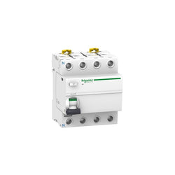
Acti 9 iID - RCCB - 4P - 63A - 30mA - type A

Main
| Characteristic | Value(s) |
|---|---|
| Range | TeSys |
| Product or Component Type | Long shaft |
| Device short name | GVAP |
| Accessory / separate part category | Control accessory |
Complementary
| Characteristic | Value(s) |
|---|---|
| Product Compatibility | GVAPB54 GVAPR54 GVAPB65 GVAPR65 |
| Length | 12.4 in (315 mm) |
| Product Weight | 0.24 lb(US) (0.11 kg) |
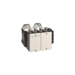
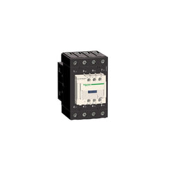
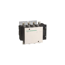
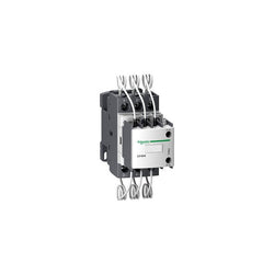
TeSys F contactor, 4 poles (4NO), 500A/1000V AC-1, for non-inductive load applications. It provides a low sealed consumption 220V 40-400Hz AC coil, bolt terminals for bars or cables with lugs. For high operating rates until 2400 cycles/hour and environments until 55°C, it procures high reliability and durability. It makes installation and maintenance easy thanks to its drawer-mounted coil and a large choice of add-on blocks and accessories (to be ordered separately). Multi standards certified (IEC, UL, CSA, CCC, EAC, Marine), Green Premium compliant (RoHS/REACh).
Main
| Characteristic | Value(s) |
|---|---|
| Range | TeSys |
| Range of Product | TeSys F |
| Product or Component Type | Contactor |
| Device short name | LC1F |
| Contactor application | Resistive load |
| Utilisation category | AC-1 |
| Poles description | 4P |
| [Ue] rated operational voltage | <= 1000 V AC 50/60 Hz <= 460 V DC |
| [Uc] control circuit voltage | 220 V AC 40...400 Hz |
| [Ie] rated operational current | 500 A (at <104 °F (40 °C)) at <= 440 V AC AC-1 |
Complementary
| Characteristic | Value(s) |
|---|---|
| [Uimp] rated impulse withstand voltage | 8 kV |
| [Ith] conventional free air thermal current | 500 A (at 104 °F (40 °C)) |
| Rated breaking capacity | 3200 A conforming to IEC 60947-4-1 |
| [Icw] rated short-time withstand current | 3600 A 104 °F (40 °C) - 10 s 2400 A 104 °F (40 °C) - 30 s 1700 A 104 °F (40 °C) - 1 min 1200 A 104 °F (40 °C) - 3 min 1000 A 104 °F (40 °C) - 10 min |
| Associated fuse rating | 400 A aM at <= 440 V 500 A gG at <= 440 V |
| Average impedance | 0.26 mOhm - Ith 500 A 50 Hz |
| [Ui] rated insulation voltage | 1000 V IEC 60947-4-1 1500 V VDE 0110 group C |
| Power dissipation per pole | 65 W AC-1 |
| Overvoltage category | III |
| power pole contact composition | 4 NO |
| Control circuit voltage limits | Operational 0.85...1.1 Uc 40...400 Hz 131 °F (55 °C)) Drop-out 0.3...0.5 Uc 40...400 Hz 131 °F (55 °C)) |
| Mechanical durability | 10 Mcycles |
| Inrush power in VA | 1075 VA, 40...400 Hz 0.9 68 °F (20 °C)) |
| Hold-in power consumption in VA | 15 VA, 40...400 Hz 0.9 68 °F (20 °C)) |
| Maximum operating rate | 2400 cyc/h 131 °F (55 °C) |
| Operating time | 40...65 ms closing 100...170 ms opening |
| Connections - terminals | Control circuit screw clamp terminals 1 0.002â¦0.006 in² (1â¦4 mm²)flexible without cable end Control circuit screw clamp terminals 2 0.002â¦0.006 in² (1â¦4 mm²)flexible without cable end Control circuit screw clamp terminals 1 0.002â¦0.006 in² (1â¦4 mm²)flexible with cable end Control circuit screw clamp terminals 2 0.002â¦0.004 in² (1â¦2.5 mm²)flexible with cable end Control circuit screw clamp terminals 1 0.002â¦0.006 in² (1â¦4 mm²)solid without cable end Control circuit screw clamp terminals 2 0.002â¦0.006 in² (1â¦4 mm²)solid without cable end Power circuit bar 2 30 x 5 mm Power circuit lugs-ring terminals 2 0.2 in² (150 mm²) Power circuit bolted connection |
| Tightening torque | Control circuit 10.6 lbf.in (1.2 N.m) Power circuit 309.8 lbf.in (35 N.m) |
| Mounting Support | Plate |
| Heat dissipation | 14 W |
| Standards | JIS C8201-4-1 IEC 60947-4-1 IEC 60947-1 EN 60947-4-1 EN 60947-1 |
| Product Certifications | RMRoS BV DNV RINA CCC ABS CB UL LROS (Lloyds register of shipping) UKCA |
| Compatibility code | LC1F |
| Control circuit type | AC 40...400 Hz |

This Acti9 C120N is a low voltage multistandard miniature circuit breaker (MCB). It is a 2P circuit breaker with 2 protected poles, 125A rated current and C tripping curve. The Icn rated short circuit breaking capacity is up to 10000A at 230VAC to 400VAC conforming to IEC/EN 60898-1 standard. This product complies with industrial standard IEC/EN 60898-1 and residential standard IEC/EN 60947-2. This miniature circuit breaker protects circuit against short circuit and overload current. The presence of green strip guarantees contact open physically and allows work to be carried out safely on the downstream circuit. It has an electrical endurance going up to 5000 cycles and a mechanical endurance going up to 20000 cycles. The Ue operational voltage is going from 380VAC to 415VAC. The Ui rated insulation voltage is 500VAC. Its limitation class 3 (according to IEC/EN 60947-2 standard) improves downstream circuit protection cost. The product can be clipped on a DIN rail. Its width is 6 pitches of 9mm. Pollution degree is 3. Overvoltage category is IV. The product colour is white (RAL 9003). The dimensions are (W) 54mm x (H) 81mm x (D) 73mm. The weight is 0.41kg. It has an IP20 degree of protection (as per IEC 60529 standard) on its terminals. The operating temperature is from -25°C to +70°C. The storage temperature is from -40°C to +85°C.
Main
| Characteristic | Value(s) |
|---|---|
| Range | Acti9 |
| product name | Acti9 C120 |
| Product or component type | Miniature circuit-breaker |
| Device short name | C120N |
| Device application | Distribution |
| Poles description | 2P |
| Number of protected poles | 2 |
| Neutral position | Left |
| [In] rated current | 125 A at 30 °C |
| Network type | AC |
| Trip unit technology | Thermal-magnetic |
| Curve code | C |
| Breaking capacity | 10000 A Icn at 230...400 V AC 50/60 Hz conforming to EN/IEC 60898-1 6 kA Icu at 440 V AC 50/60 Hz conforming to EN/IEC 60947-2 10 kA Icu at <= 250 V DC conforming to EN/IEC 60947-2 20 kA Icu at 220...240 V AC 50/60 Hz conforming to EN/IEC 60947-2 10 kA Icu at 380...415 V AC 50/60 Hz conforming to EN/IEC 60947-2 |
| Suitability for isolation | Yes conforming to IEC 60947-2 |
| Standards | EN/IEC 60947-2 EN/IEC 60898-1 |
| Product certifications | EAC |
Complementary
| Characteristic | Value(s) |
|---|---|
| Network frequency | 50/60 Hz |
| [Ue] rated operational voltage | 380...415 V AC 50/60 Hz 220...240 V AC 50/60 Hz 440 V AC 50/60 Hz <= 250 V DC 230...400 V AC 50/60 Hz |
| Magnetic tripping limit | 5...10 x In |
| [Ics] rated service breaking capacity | 7500 A 75 % conforming to EN/IEC 60898-1 - 230...400 V AC 50/60 Hz 4.5 kA 75 % conforming to EN/IEC 60947-2 - 440 V AC 50/60 Hz 7.5 kA 75 % conforming to EN/IEC 60947-2 - 380...415 V AC 50/60 Hz 15 kA 75 % conforming to EN/IEC 60947-2 - 220...240 V AC 50/60 Hz 10 kA 100 % conforming to EN/IEC 60947-2 - <= 250 V DC |
| Limitation class | 3 conforming to EN/IEC 60947-2 |
| [Ui] rated insulation voltage | 500 V AC 50/60 Hz conforming to EN/IEC 60947-2 |
| [Uimp] rated impulse withstand voltage | 6 kV conforming to EN/IEC 60947-2 |
| Contact position indicator | Yes |
| control type | Toggle |
| Local signalling | ON/OFF indication |
| Mounting mode | Clip-on |
| Mounting support | 35 mm symmetrical DIN rail |
| Comb busbar and distribution block compatibility | YES |
| 9 mm pitches | 6 |
| Height | 81 mm |
| Depth | 73 mm |
| Width | 54 mm |
| Product weight | 0.41 kg |
| Colour | White |
| Mechanical durability | 20000 cycles |
| Electrical durability | 5000 cycles conforming to IEC 60947-2 |
| Locking options description | Handle sealable with cable diameter 0.7mm in OFF or ON position |
| Connections - terminals | Tunnel type terminals1â¦50 mm² rigid Tunnel type terminals1.5â¦35 mm² flexible |
| Wire stripping length | 15 mm |
| Tightening torque | 3.5 N.m |
| Earth-leakage protection | Separate block |
TeSys F contactor - 4P (4 NO) - AC-1 - <= 440 V 200 A - coil 110 V AC
TeSys D contactor 3P 66A AC-3 up to 440V coil 48-130V AC/DC EverLink
TeSys D contactor - 3P(3 NO) - AC-3 - <= 440 V 150 A - 110 V AC 50/60 Hz coil

Miniature circuit-breaker, Acti9 iC60H, 2P, 10 A, D curve, 10000 A (IEC 60898-1), 15 kA (IEC 60947-2)
TeSys D contactor - 3P(3 NO) - AC-3 - <= 440 V 50 A - 48 V AC 50/60 Hz coil

C120N - circuit breaker - 3P - 100A - B curve

Motor circuit breaker, TeSys GV4, 3P, 80A, Icu 50kA, thermal magnetic, Everlink terminals


PLC Direct is not an authorized distributor. We offer a broad range of in-stock products with minimal lead time.
This Acti9 iC60 is a modular residual current breaker with overcurrent protection (RCBO). It is a 2P RCBO with 2 protected poles, rated current is 32A, and operating voltage is 220VAC to 240VAC. The earth leakage protection class is A type with a sensitivity of 300mA. The earth-leakage protection time delay is instantaneous. Breaking capacity at 220VAC to 240VAC is 10000A according to EN/IEC 61009-2-1. Breaking capacity at 220VAC to 240VAC is 15kA according to EN/IEC 60947-2. Its fast closing mechanism independent of manual operation improves its service life. This product is compliant with EN/IEC 60947-2 and EN/IEC 61009-2-1 standards. Electrical endurance goes up to 10000 cycles, and mechanical endurance goes up to 20000 cycles. The Ue operational voltage is 220VAC to 240VAC. The Ui rated insulation voltage is 500VAC. The Uimp rated impulse withstand voltage is 4kV. The frequency is 50Hz. It is DIN rail mountable. The width in 9mm pitches is 4. The product color is white (RAL9003). The dimensions are (W) 36mm x (H) 86mm x (D) 78mm. The weight is 273g. According to IEC 60529 standard, the degree of protection is IP20 and IP40 in enclosure. The operating temperature is from -25°C to 40°C. The storage temperature is from -40°C to 70°C.
Main
| Characteristic | Value(s) |
|---|---|
| Range | Acti9 |
| product name | Acti9 iC60 RCBO |
| Product or component type | Residual current breaker with overcurrent protection (RCBO) |
| Device short name | iC60 RCBO |
| Device application | Distribution |
| Poles description | 2P |
| Number of protected poles | 2 |
| [In] rated current | 32 A |
| Network type | AC |
| Network frequency | 50 Hz |
| Trip unit technology | Thermal-magnetic |
| Curve code | C |
| Earth-leakage sensitivity | 300 mA |
| Suitability for isolation | No conforming to IEC 60947-1 |
| Quality labels | KEMA-KEUR IMQ VDE NF |
Complementary
| Characteristic | Value(s) |
|---|---|
| Device location in system | Outgoer |
| [Ue] rated operational voltage | 220...240 V AC 50 Hz |
| Magnetic tripping limit | 5...10 x In |
| Residual current tripping technology | Voltage independent |
| Earth-leakage protection time delay | Instantaneous |
| Earth-leakage protection class | Type A |
| Breaking capacity | 10000 A Icn at 220...240 V AC 50 Hz conforming to EN/IEC 61009-2-1 15 kA Icu at 220...240 V AC 50 Hz conforming to EN/IEC 60947-2 |
| [Ics] rated service breaking capacity | 7500 A 75 % x Icn at 220...240 V AC 50 Hz conforming to EN/IEC 61009-2-1 7.5 kA 50 % x Icu at 220...240 V AC 50 Hz conforming to EN/IEC 60947-2 |
| Rated breaking and making capacity | Idm 6000 A at 220...240 V AC 50 Hz conforming to EN/IEC 61009-2-1 |
| Limitation class | 3 conforming to EN/IEC 61009-2-1 |
| [Ui] rated insulation voltage | 500 V AC 50 Hz |
| [Uimp] rated impulse withstand voltage | 4 kV |
| Surge current | 250 A |
| Contact position indicator | No |
| control type | Toggle |
| Local signalling | ON, OFF, fault trip |
| Mounting mode | Clip-on |
| Mounting support | DIN rail |
| Comb busbar and distribution block compatibility | Top or bottom: YES Bottom: biconnect |
| Connection pitch | 9 mm between poles |
| 9 mm pitches | 4 |
| Height | 86 mm |
| Width | 36 mm |
| Depth | 78 mm |
| Product weight | 273 g |
| Colour | White |
| Mechanical durability | 20000 cycles |
| Electrical durability | 10000 cycles |
| Connections - terminals | Tunnel type terminal top or bottom 1â¦35 mm² rigid Tunnel type terminal top or bottom 1â¦25 mm² flexible Tunnel type terminal top or bottom 1â¦25 mm² flexible with ferrule |
| Wire stripping length | 12 mm for top or bottom connection |
| Tightening torque | 2 N.m |
| Earth-leakage protection | Integrated |
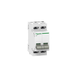
switch Acti9 iSW - 4 poles - 32 A - 415V
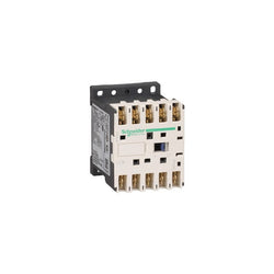
TeSys K contactor - 3P - AC-3 <= 440 V 6 A - 1 NO aux. - 380...400 V AC coil
Capacitor contactor, TeSys D, 25 kVAR at 400 V/50 Hz, coil 400 V AC 50/60 Hz