
 1 year warranty


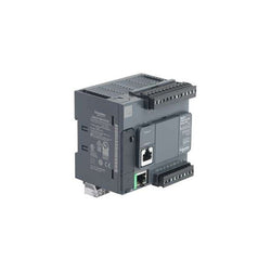
The M340 processor module has a maximum of 1024 discrete and 256 analog I/O (Modbus or Ethernet). 36 application specific channels, product or component type. The processor module can do monitoring, diagnostic counters Modbus, event counters Modbus, is transparent ready, has 4 CANopen racks and 11 slots. It also has 1024 I/O multirack configuration, 704 I/O single rack configuration, analog I/O processor capacity, 256 I/O multirack configuration and 66 I/O single rack configuration. The Modicon M340 offers in a small form factor flexibility and integrated functions. In the heart of your process, it provides plug-and-play solutions with both Schneider Electric and third party devices. The large capacity of Unity Pro SoCollaborative software will ease and shorten programming and commissioning time. Modicon M340 Programmable Automation Controllers (PACs) are built to suit the needs of the process industry and a wide range of demanding automation applications. Modicon M340 PACs can be used individually, but are also the perfect companion to the Modicon M580. Together they can increase the performance, quality, and the profitability of your machine production. M340 PACs have an all in one CPU. It operates at 7 Kinst/ms. By using a multitasking system, it has reflex time. This PAC is programmed with Unity⢠Pro software. The M340 has a USB port for programming and HMI. Two additional Ethernet, CANopen® or Modbus⢠ports are available as required. The memory can process programming code up to 70 Kinst. Application back up is in a supplied memory card. Additional file storage is available up to 128 MB with FTP access. Additional file storage is available up to 128 MB with FTP access. The M340 range doesnât require a battery. It has extended temperature (-25°C +70°C) and conformal coating for operation in harsh environments. Protection for SI and OEM know how by using a SD card technology. Replace or hot swap I/O modules without stopping process. Configuration change on the fly (CCOTF) is used. No need to stop the process to expand system. FTD/DTM configuration tools for plug and play device integration. This simplifies configuration, commissioning, and maintenance. The M340 range is used in process industries, renewable energy applications (Solar, Wind power, etc.), water and cement applications, in manufacturing, in infrastructures and on machines.
Main
| Characteristic | Value(s) |
|---|---|
| Range of Product | Modicon M340 automation platform |
| Product or Component Type | Processor module |
| Concept | Transparent Ready CANopen |
| Number of racks | 4 |
| Number of slots | 11 |
| Discrete I/O processor capacity | 1024 I/O multi-rack configuration 704 I/O single-rack configuration |
| Analogue I/O processor capacity | 256 I/O multi-rack configuration 66 I/O single-rack configuration |
| Number of application specific channel | 36 |
| Monitoring | Diagnostic counters Modbus Event counters Modbus |
Complementary
| Characteristic | Value(s) |
|---|---|
| Control channels | Programmable loops |
| Integrated connection type | Non isolated serial link RJ45 character mode asynchronous in baseband, RS232C 2 twisted shielded pairs 0.3...19.2 kbit/s full duplex Non isolated serial link RJ45 character mode asynchronous in baseband, RS485 1 twisted shielded pair 0.3...19.2 kbit/s half duplex Non isolated serial link RJ45, master/slave Modbus, RTU/ASCII asynchronous in baseband, RS232C 1 twisted shielded pair 0.3...19.2 kbit/s half duplex Non isolated serial link RJ45, master/slave Modbus, RTU/ASCII asynchronous in baseband, RS485 1 twisted shielded pair 0.3...19.2 kbit/s half duplex USB port 12 Mbit/s Ethernet TCP/IP RJ45 1 twisted pair 10/100 Mbit/s |
| Communication module processor capacity | 2 Ethernet communication module 4 AS-Interface module |
| embedded communication service | Bandwidth management, Ethernet TCP/IP Data Editor, Ethernet TCP/IP Modbus TCP messaging, Ethernet TCP/IP Rack Viewer, Ethernet TCP/IP SNMP network administrator, Ethernet TCP/IP |
| Port Ethernet | 10BASE-T/100BASE-TX |
| Number of devices per segment | 0â¦32character mode) 0â¦32Modbus) |
| Number of devices | 2 point-to-point character mode 2 point-to-point Modbus |
| Bus length | 0.0000000000â¦32.8 ft (0â¦10 m) serial link non isolated character mode segment 0.0000000000â¦32.8 ft (0â¦10 m) serial link non isolated Modbus segment 0.0000000000â¦3280.8 ft (0â¦1000 m) serial link isolated character mode segment 0.0000000000â¦3280.8 ft (0â¦1000 m) serial link isolated Modbus segment 0.0000000000â¦49.2 ft (0â¦15 m) character mode point-to-point 0.0000000000â¦49.2 ft (0â¦15 m) Modbus point-to-point |
| Maximum tap links length | <49.2 ft (15 m) serial link non isolated character mode segment <49.2 ft (15 m) serial link non isolated Modbus segment <131.2 ft (40 m) serial link isolated character mode segment <131.2 ft (40 m) serial link isolated Modbus segment |
| Number of addresses | 0â¦248 character mode 0â¦248 Modbus |
| Requests | 1 K data bytes per request character mode 252 data bytes per RTU request Modbus 504 data bytes per ASCII request Modbus |
| Control parameter | One CRC on each frame (RTU) Modbus One LRC on each frame (ASCII) character mode One LRC on each frame (ASCII) Modbus |
| Memory description | Supplied memory card (BMXRMS008MP) backup of programs, constants, symbols and data Internal RAM 4096 kB Internal RAM 256 kB data Internal RAM 3584 kB program constants and symbols Supplied memory card (BMXRMS008MP) activation of standard web server, class B10 |
| Maximum size of object areas | 256 kB unlocated internal data 32634 %Mi located internal bits |
| Default size of object areas | 1024 %MWi internal words located internal data 256 %KWi constant words located internal data 512 %Mi located internal bits |
| Application structure | 1 cyclic/periodic master task 1 periodic fast task No auxiliary task 64 event tasks |
| Execution time per instruction | 0.12 µs Boolean 0.17 µs double-length words 0.25 µs single-length words 1.16 µs floating points |
| Number of instructions per ms | 6.4 Kinst/ms 65 % Boolean + 35 % fixed arithmetic 8.1 Kinst/ms 100 % Boolean |
| System overhead | 0.13 ms fast task 0.7 ms master task |
| Current consumption | 95 mA 24 V DC |
| Supply | Internal power supply via rack |
| Marking | CE |
| Status LED | 1 LED (Green) activity on Ethernet network (ETH ACT) 1 LED (Green) processor running (RUN) 1 LED (Green) status of Ethernet network (ETH STS) 1 LED (Red) data rate (ETH 100) 1 LED (Red) I/O module fault (I/O) 1 LED (Red) memory card fault (CARD ERR) 1 LED (Red) processor or system fault (ERR) 1 LED (Yellow) activity on Modbus (SER COM) |
| Product Weight | 0.452 lb(US) (0.205 kg) |

Modicon M221 Controller M221 40 IO relay Ethernet
Logic controller, Modicon M241, 24 IO transistor PNP Ethernet
Main
| Characteristic | Value(s) |
|---|---|
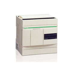
| Range of Product | Twido |
| Product or Component Type | Compact base controller |
| Discrete I/O number | 24 |
| Discrete input number | 14 |
| Discrete input voltage | 24 V |
| Discrete input voltage type | DC |
| Discrete output number | 10 relay |
| [Us] rated supply voltage | 100...240 V AC |
| Maximum Number of I/O Expansion Module | 4 |
| Use of slot | Memory cartridge or realtime clock cartridge |
| Data backed up | Internal RAM lithium, 30 days 10 h 10 year(s) |
| Integrated connection type | Power supply Non isolated serial link mini DIN, Modbus/character mode master/slave RTU/ASCII RS485) half duplex, 38.4 kbit/s Serial link interface adaptor RS232C/RS485) |
| Complementary function | Event processing PID |
| Range Compatibility | Twido |
Complementary
| Characteristic | Value(s) |
|---|---|
| Discrete input logic | Sink or source |
| Input voltage limits | 20.4...28.8 V |
| Discrete input current | 11 mA I0.0 to I0.1 7 mA I0.2 to I0.13 |
| Input impedance | 2100 Ohm I0.0 to I0.1 3400 Ohm I0.2 to I0.13 |
| Filter time | 150 µs + programmed filter time for I0.6 to I0.13 at state 0 35 µs + programmed filter time for I0.0 to I0.5 at state 1 40 µs + programmed filter time for I0.6 to I0.13 at state 1 45 µs + programmed filter time for I0.0 to I0.5 at state 0 |
| Insulation between channel and internal logic | 1500 Vrms for 1 minute |
| Insulation resistance between channel | None |
| Minimum load | 0.1 mA |
| Contact resistance | 30000 µOhm |
| Load current | 2 A 240 V AC inductive 30 cyc/mn relay output 2 A 240 V AC resistive 30 cyc/mn relay output 2 A 30 V DC inductive 30 cyc/mn relay output 2 A 30 V DC resistive 30 cyc/mn relay output |
| Mechanical durability | 20000000 cycles relay output |
| Electrical durability | 100000 cycles relay output |
| Current consumption | 36 mA 5 V DC at state 1 5 mA 5 V DC at state 0 55 mA 24 V DC at state 1 |
| I/O connection | Non-removable screw terminal block |
| Maximum input/output number | 120 spring terminal block with I/O expansion module 152 HE-10 connector with I/O expansion module 88 removable screw terminal block with I/O expansion module |
| Network Frequency | 50/60 Hz |
| Supply voltage limits | 85â¦264 V |
| Network frequency limits | 47â¦63 Hz |
| Power supply output current | 0.25 A 24 V DC sensors |
| Input current | 450 mA |
| Inrush current | 40 A |
| Protection type | Power protection internal fuse |
| Power consumption in VA | 33 VA 100 V 40 VA 264 V |
| Insulation resistance | > 10 MOhm at 500 V, between I/O and earth terminals > 10 MOhm at 500 V, between supply and earth terminals |
| Program memory | 3000 instructions |
| Exact time for 1 Kinstruction | 1 ms |
| System overhead | 0.5 ms |
| Memory description | Internal RAM, 128 counters, no floating, no trigonometrical Internal RAM, 128 timers, no floating, no trigonometrical Internal RAM, 256 internal bits, no floating, no trigonometrical Internal RAM, 3000 internal words, no floating, no trigonometrical Internal RAM, double words, no floating, no trigonometrical |
| Free slots | 1 |
| Realtime clock | Without |
| Counting input number | 1 20000 Hz 32 bits 3 5000 Hz 16 bits |
| Analogue adjustment points | 1 point adjustable from 0 to 511 points 1 point adjustable from 0...1023 |
| Status LED | 1 LED (Green) PWR 1 LED (Green) RUN 1 LED per channel (Green) I/O status 1 LED (Red) module error (ERR) 1 LED user pilot light (STAT) |
| Depth | 2.8 in (70 mm) |
| Height | 3.7 in (95 mm) |
| Width | 3.5 in (90 mm) |
| Terminals description PLC n°1 | (6)IN_DIS#6 COM_NEG#0-13 (-)PW_OUT_NEG (4)IN_DIS#4 ALT (0)IN_DIS#0 (13)IN_DIS#13 (5)IN_DIS#5 (8)IN_DIS#8 (10)IN_DIS#10 (11)IN_DIS#11 TB_TOP (+)PW_OUT_POS (9)IN_DIS#9 (3)IN_DIS#3 (7)IN_DIS#7 (12)IN_DIS#12 (1)IN_DIS#1 (2)IN_DIS#2 |
| Terminals description PLC n°2 | (11)IN_DIS#10 (9)IN_DIS#9 (2)IN_DIS#2 (1)IN_DIS#1 (7)IN_DIS#7 (3)IN_DIS#3 (8)IN_DIS#8 (+)PW_OUT_POS ALT_1 COM_POS#0-13 (12)IN_DIS#12 (-)PW_OUT_NEG (4)IN_DIS#4 (13)IN_DIS#13 TB_TOP (6)IN_DIS#6 (10)IN_DIS#10 (0)IN_DIS#0 (5)IN_DIS#5 |
| Terminals description PLC n°3 | (COM0)COM#0-3 (9)OUT_DIS#9 (7)OUT_DIS#7 (3)OUT_DIS#3 (1)OUT_DIS#1 (GND)GROUND (6)OUT_DIS#6 (-)PW_NEG (COM2)COM#8 TB_BOTTOM (COM1)COM#4-7 (8)OUT_DIS#8 (COM3)COM#9 (5)OUT_DIS#5 (4)OUT_DIS#4 (2)OUT_DIS#2 (0)OUT_DIS#0 (+)PW_POS |
| Product Weight | 0.672 lb(US) (0.305 kg) |
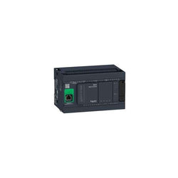
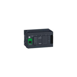
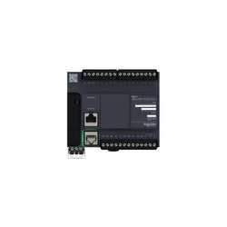
This product is part of the Modicon M241 range, an offer of logic controllers for performance demanding applications. This logic controller provides 14 discrete, 8 fast inputs, 6 relay, 4 transistor, 4 fast outputs with transistor, ethernet relay output. It has a rated supply voltage of 100V to 240V AC, an output voltage of 5V to 125V DC or 5V to 250V AC for relay, 24V DC for transistor and an output current of 2A for relay, 0.1A for fast output, 0.5A for transistor. This product enables to build application intuitively as never before due to an organised screen design. Integrated connections are USB port with mini B USB 2.0 connector, non isolated serial link 1 with RJ45 connector and RS232/RS485 interface and non isolated serial link 2 with removable screw terminal block connector and RS485 interface. It is a Modicon M241 controller with 8MB for program, 64MB for system memory RAM, 128MB built-in flash memory for backup of user programs and a SD card memory capacity of 16GB. It is an IP20 rated product. Its dimensions are 150mm (Width) x 95mm (Depth) x 90mm (Height). It weighs 0.53kg. The Modicon M241 logic controllers are designed for high-performance compact machines incorporating speed and position control functions. This product is certified by CE, IACS E10, RCM, CSA, CULus. It meets ANSI/ISA 12-12-01, CSA C22.2 No 142, CSA C22.2 No 213, EN/IEC 61131-22007, marine specification (LR, ABS, DNV, GL), UL 1604 and UL 508 standards. It supports DIN rail mount. Achieve benchmark performance while increasing profitability with the Modicon M241 through intuitive machine programming with EcoStruxure Machine Expert, ready-to-use applications and function blocks.
Main
| Characteristic | Value(s) |
|---|---|
| Range of Product | Modicon M241 |
| Product or Component Type | Logic controller |
| [Us] rated supply voltage | 100...240 V AC |
| Discrete input number | 14, discrete input 8 fast input IEC 61131-2 Type 1 |
| Discrete output type | Relay Transistor |
| Discrete output number | 6 relay 4 transistor 4 fast output |
| Discrete output voltage | 5...125 V DC relay output 5...250 V AC relay output 24 V DC transistor output |
| Discrete output current | 2 A relay output Q4...Q9) 0.1 A fast output (PTO mode) TR0...TR3) 0.5 A transistor output TR0...TR3) |
Complementary
| Characteristic | Value(s) |
|---|---|
| Discrete I/O number | 24 |
| Maximum number of I/O expansion module | 7 (local I/O-Architecture) 14 (remote I/O-Architecture) |
| Supply voltage limits | 85â¦264 V |
| Network Frequency | 50/60 Hz |
| Discrete input logic | Sink or source |
| Discrete input voltage | 24 V |
| Discrete input voltage type | DC |
| Voltage state 1 guaranteed | >= 15 V input |
| Voltage state 0 guaranteed | <= 5 V input |
| Discrete input current | 5 mA input |
| Input impedance | 4.7 kOhm input |
| Response time | 50 µs turn-on, I0...I13 input |
| Configurable filtering time | 1 µs fast input |
| Discrete output logic | Positive logic (source) |
| Output voltage limits | 125 V DC relay output 30 V DC transistor output 277 V AC relay output |
| Maximum output frequency | 1 kHz transistor output 20 kHz fast output (PWM mode) 100 kHz fast output (PLS mode) |
| Accuracy | +/- 0.1 % 0.02â¦0.1 kHz fast output +/- 1 % 0.1â¦1 kHz fast output |
| Protection type | Short-circuit protection transistor output Short-circuit and overload protection with automatic reset transistor output Reverse polarity protection transistor output Without protection relay output |
| Reset time | 10 ms automatic reset output 12 s automatic reset fast output |
| Memory capacity | 64 MB system memory RAM |
| Data backed up | 128 MB built-in flash memory backup of user programs |
| Data storage equipment | <= 16 GB SD card optional) |
| Battery type | BR2032 lithium non-rechargeable 4 year(s) |
| Backup time | 2 years 77 °F (25 °C) |
| Execution time for 1 KInstruction | 0.3 ms event and periodic task 0.7 ms other instruction |
| Application structure | 8 external event tasks 3 cyclic master tasks + 1 freewheeling task 8 event tasks 4 cyclic master tasks |
| Realtime clock | With |
| Clock drift | <= 60 s/month 77 °F (25 °C) |
| Positioning functions | PTO 4 100 kHz) |
| Counting input number | 4 fast input (HSC mode) 200 kHz 14 standard input 1 kHz |
| Control signal type | A/B 100 kHz fast input (HSC mode) Pulse/direction 200 kHz fast input (HSC mode) Single phase 200 kHz fast input (HSC mode) |
| Integrated connection type | Non isolated serial link serial 1 RJ45 RS232/RS485 Non isolated serial link serial 2 removable screw terminal block RS485 USB port mini B USB 2.0 Ethernet RJ45 |
| Supply | Serial 1)serial link supply 5 V, <200 mA |
| Transmission rate | 1.2...115.2 kbit/s (115.2 kbit/s by default) 49.2 ft (15 m) RS485 1.2...115.2 kbit/s (115.2 kbit/s by default) 9.8 ft (3 m) RS232 480 Mbit/s 9.8 ft (3 m) USB 10/100 Mbit/s Ethernet |
| Communication port protocol | Non isolated serial link Modbus master/slave |
| Port Ethernet | 10BASE-T/100BASE-TX - 1 copper cable |
| ethernet services | FDR DHCP server via TM4 Ethernet switch network module DHCP client embedded Ethernet port SMS notifications Updating firmware SNMP client/server Programming NGVL Monitoring IEC VAR ACCESS FTP client/server Downloading SQL client Modbus TCP client I/O scanner Ethernet/IP originator I/O scanner embedded Ethernet port Ethernet/IP target, Modbus TCP server and Modbus TCP slave Send and receive email from the controller based on TCP/UDP library Web server (WebVisu & XWeb system) OPC UA server DNS client |
| Local signalling | 1 LED (green) for PWR 1 LED (green) for RUN 1 LED (red) for module error (ERR) 1 LED (red) for I/O error (I/O) 1 LED (green) for SD card access (SD) 1 LED (red) for BAT 1 LED (green) for SL1 1 LED (green) for SL2 1 LED (red) for bus fault on TM4 (TM4) 1 LED per channel (green) for I/O state 1 LED (green) for Ethernet port activity |
| Electrical connection | removable screw terminal block for inputs and outputs pitch 5.08 mm) removable screw terminal block for connecting the 24 V DC power supply pitch 5.08 mm) |
| Maximum cable distance between devices | Unshielded cable <164.04 ft (50 m) input Shielded cable <32.8 ft (10 m) fast input Unshielded cable <164.04 ft (50 m) output Shielded cable <9.8 ft (3 m) fast output |
| Insulation | Between supply and internal logic 500 V AC Non-insulated between supply and ground |
| Marking | CE |
| Sensor power supply | 24 V DC 400 mA supplied by the controller |
| Surge withstand | 2 kV power lines (AC) common mode IEC 61000-4-5 2 kV relay output common mode IEC 61000-4-5 1 kV shielded cable common mode IEC 61000-4-5 1 kV power lines (AC) differential mode IEC 61000-4-5 1 kV relay output differential mode IEC 61000-4-5 1 kV input common mode IEC 61000-4-5 1 kV transistor output common mode IEC 61000-4-5 |
| Web services | Web server |
| Maximum number of connections | 8 Modbus server 8 SoMachine protocol 10 web server 4 FTP server 16 Ethernet/IP target 8 Modbus client |
| Number of server device(s) | 64 Modbus TCP 16 EtherNet/IP |
| Cycle time | 10 ms 16 EtherNet/IP 64 ms 64 Modbus TCP |
| Mounting support | Top hat type TH35-15 rail IEC 60715 Top hat type TH35-7.5 rail IEC 60715 plate or panel with fixing kit |
| Height | 3.5 in (90 mm) |
| Depth | 3.7 in (95 mm) |
| Width | 5.9 in (150 mm) |
| Product Weight | 1.17 lb(US) (0.53 kg) |
Logic controller, Modicon M221, 24 IO relay
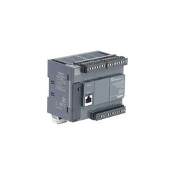
This product is part of the Modicon M221 range, an offer of programmable logic controllers for hardwired architectures. This logic controller provides 9 discrete inputs and 7 relay ethernet outputs with 10bit input resolution, normally opened relay output. It is a Modicon logic controller with a rated supply voltage of 100V to 240V AC, an output voltage of 5V to 125V DC, 5V to 250V AC and an output current of 2A with sink or source input logic. This product requires minimal installation and offers tremendous versatility. Integrated connections are USB port with mini B USB 2.0 connector, non isolated serial link serial 1 with RJ45 connector and RS232/RS485 interface and ethernet with RJ45 connector. It is a Modicon M221 controller with a network frequency of 50/60Hz, 256KB for internal variables RAM, user application and data RAM, a built-in flash memory of 256KB and a SD card memory capacity of 2GB. It is an IP20 rated product. Its dimensions are 95mm (Width) x 70mm (Depth) x 90mm (Height). It weighs 0.346kg. This product is certified by CE, IACS E10, RCM, ABS, LR, DNV-GL, CSA, EAC and CULus. It meets EN/IEC 60664-1, EN/IEC 61131-2 and EN/IEC 61010-2-201 standards. It supports DIN rail mount. Achieve benchmark performance while increasing profitability with the Modicon M221 through intuitive machine programming with SoMachine Basic, ready-to-use applications and function blocks
Main
| Characteristic | Value(s) |
|---|---|
| Range of Product | Modicon M221 |
| Product or Component Type | Logic controller |
| [Us] rated supply voltage | 100...240 V AC |
| Discrete input number | 9, discrete input IEC 61131-2 Type 1 |
| Analogue input number | 2 0...10 V |
| Discrete output type | Relay normally open |
| Discrete output number | 7 relay |
| Discrete output voltage | 5...125 V DC 5...250 V AC |
| Discrete output current | 2 A |
Complementary
| Characteristic | Value(s) |
|---|---|
| Discrete I/O number | 16 |
| Maximum number of I/O expansion module | 4 (local I/O-Architecture) 11 (remote I/O-Architecture) |
| Supply voltage limits | 85â¦264 V |
| Network Frequency | 50/60 Hz |
| Inrush current | 40 A |
| Maximum power consumption in VA | 49 VA 100...240 V with max number of I/O expansion module 33 VA 100...240 V without I/O expansion module |
| Power supply output current | 0.325 A 5 V expansion bus 0.12 A 24 V expansion bus |
| Discrete input logic | Sink or source (positive/negative) |
| Discrete input voltage | 24 V |
| Discrete input voltage type | DC |
| Analogue input resolution | 10 bits |
| LSB value | 10 mV |
| Conversion time | 1 ms per channel + 1 controller cycle time analog input |
| Permitted overload on inputs | +/- 30 V DC 5 min maximum)analog input +/- 13 V DC permanent)analog input |
| Voltage state 1 guaranteed | >= 15 V input |
| Voltage state 0 guaranteed | <= 5 V input |
| Discrete input current | 7 mA discrete input 5 mA fast input |
| Input impedance | 3.4 kOhm discrete input 100 kOhm analog input 4.9 kOhm fast input |
| Response time | 35 µs turn-off, I2...I5 input 10 ms turn-on output 10 ms turn-off output 5 µs turn-on, I0, I1, I6, I7 fast input 35 µs turn-on, other terminals input 5 µs turn-off, I0, I1, I6, I7 fast input 100 µs turn-off, other terminals input |
| Configurable filtering time | 0 ms input 3 ms input 12 ms input |
| Output voltage limits | 125 V DC 277 V AC |
| Maximum current per output common | 6 A COM 1 7 A COM 0 |
| Absolute accuracy error | +/- 1 % of full scale analog input |
| Electrical durability | 100000 cycles AC-12, 120 V, 240 VA, resistive 100000 cycles AC-12, 240 V, 480 VA, resistive 300000 cycles AC-12, 120 V, 80 VA, resistive 300000 cycles AC-12, 240 V, 160 VA, resistive 100000 cycles AC-15, cos phi = 0.35, 120 V, 60 VA, inductive 100000 cycles AC-15, cos phi = 0.35, 240 V, 120 VA, inductive 300000 cycles AC-15, cos phi = 0.35, 120 V, 18 VA, inductive 300000 cycles AC-15, cos phi = 0.35, 240 V, 36 VA, inductive 100000 cycles AC-14, cos phi = 0.7, 120 V, 120 VA, inductive 100000 cycles AC-14, cos phi = 0.7, 240 V, 240 VA, inductive 300000 cycles AC-14, cos phi = 0.7, 120 V, 36 VA, inductive 300000 cycles AC-14, cos phi = 0.7, 240 V, 72 VA, inductive 100000 cycles DC-12, 24 V, 48 W, resistive 300000 cycles DC-12, 24 V, 16 W, resistive 100000 cycles DC-13, 24 V, 24 W, inductive (L/R = 7 ms) 300000 cycles DC-13, 24 V, 7.2 W, inductive (L/R = 7 ms) |
| Switching frequency | 20 switching operations/minute with maximum load |
| Mechanical durability | 20000000 cycles relay output |
| Minimum load | 1 mA 5 V DC relay output |
| Protection type | Without protection 5 A |
| Reset time | 1 s |
| Memory capacity | 256 kB user application and data RAM 10000 instructions 256 kB internal variables RAM |
| Data backed up | 256 kB built-in flash memory backup of application and data |
| Data storage equipment | 2 GB SD card optional) |
| Battery type | BR2032 or CR2032X lithium non-rechargeable |
| Backup time | 1 year 77 °F (25 °C) by interruption of power supply) |
| Execution time for 1 KInstruction | 0.3 ms event and periodic task |
| Execution time per instruction | 0.2 µs Boolean |
| Exct time for event task | 60 µs response time |
| Maximum size of object areas | 255 %C counters 512 %KW constant words 255 %TM timers 512 %M memory bits 8000 %MW memory words |
| Realtime clock | With |
| Clock drift | <= 30 s/month 77 °F (25 °C) |
| Regulation loop | Adjustable PID regulator up to 14 simultaneous loops |
| Counting input number | 4 fast input (HSC mode) 100 kHz 32 bits |
| counter function | Pulse/direction A/B Single phase |
| Integrated connection type | USB port mini B USB 2.0 Non isolated serial link serial 1 RJ45 RS232/RS485 Ethernet RJ45 |
| Supply | Serial)serial link supply 5 V, <200 mA |
| Transmission rate | 1.2...115.2 kbit/s (115.2 kbit/s by default) 49.2 ft (15 m) RS485 1.2...115.2 kbit/s (115.2 kbit/s by default) 9.8 ft (3 m) RS232 480 Mbit/s USB |
| Communication port protocol | USB port USB - SoMachine-Network Non isolated serial link Modbus master/slave - RTU/ASCII or SoMachine-Network Ethernet |
| Port Ethernet | 10BASE-T/100BASE-TX 1 328.08 ft (100 m) copper cable |
| Communication Service | DHCP client Ethernet/IP adapter Modbus TCP server Modbus TCP slave device Modbus TCP client |
| Local signalling | 1 LED (green) for PWR 1 LED (green) for RUN 1 LED (red) for module error (ERR) 1 LED (green) for SD card access (SD) 1 LED (red) for BAT 1 LED per channel (green) for I/O state 1 LED (green) for SL Ethernet network activity (green) for ACT Ethernet network link (yellow) for Link (Link Status) |
| Electrical connection | removable screw terminal block for inputs removable screw terminal block for outputs terminal block, 3 for connecting the 24 V DC power supply connector, 4 for analogue inputs Mini B USB 2.0 connector for a programming terminal |
| Maximum cable distance between devices | Shielded cable <32.8 ft (10 m) fast input Unshielded cable <98.4 ft (30 m) output Unshielded cable <98.4 ft (30 m) digital input Unshielded cable <3.3 ft (1 m) analog input |
| Insulation | Between input and internal logic 500 V AC Non-insulated between analogue input and internal logic Non-insulated between analogue inputs Between supply and ground 1500 V AC Between sensor power supply and ground 500 V AC Between input and ground 500 V AC Between output and ground 1500 V AC Between supply and internal logic 2300 V AC Between sensor power supply and internal logic 500 V AC Between output and internal logic 2300 V AC Between Ethernet terminal and internal logic 500 V AC Between supply and sensor power supply 2300 V AC |
| Marking | CE |
| Sensor power supply | 24 V DC 250 mA supplied by the controller |
| Mounting support | Top hat type TH35-15 rail IEC 60715 Top hat type TH35-7.5 rail IEC 60715 plate or panel with fixing kit |
| Height | 3.5 in (90 mm) |
| Depth | 2.8 in (70 mm) |
| Width | 3.7 in (95 mm) |
| Product Weight | 0.763 lb(US) (0.346 kg) |
This TM221 controller is part of the Modicon M221 Logic controller range. It has 24 logic I/O and it is supplied with 24V DC. It is supplied with removable screw terminal blocks for connecting the I/O, a removable screw terminal block for connecting the power supply, a button cell backup battery BR2032 and a cable for connecting the analog inputs. M221 logic controllers have three types of integrated communication port, Ethernet, RS 232/RS 485 serial link and USB mini-B programming port. It enables the control of simple machines. The capacity of M221 logic controllers can be enhanced with the Modicon TM3 expansion module offer.
Main
| Characteristic | Value(s) |
|---|---|
| Range of Product | Modicon M221 |
| Product or Component Type | Logic controller |
| [Us] rated supply voltage | 24 V DC |
| Discrete input number | 14, discrete input 4 fast input IEC 61131-2 Type 1 |
| Analogue input number | 2 0...10 V |
| Discrete output type | Transistor |
| Discrete output number | 10 transistor 2 fast output |
| Discrete output voltage | 24 V DC |
| Discrete output current | 0.5 A |
Complementary
| Characteristic | Value(s) |
|---|---|
| Discrete I/O number | 24 |
| Maximum number of I/O expansion module | 7 (local I/O-Architecture) 14 (remote I/O-Architecture) |
| Supply voltage limits | 20.4â¦28.8 V |
| Inrush current | 35 A |
| Maximum power consumption in W | 14 W 24 V with max number of I/O expansion module) 4.8 W 24 V without I/O expansion module) |
| Power supply output current | 0.52 A 5 V expansion bus 0.2 A 24 V expansion bus |
| Discrete input logic | Sink or source (positive/negative) |
| Discrete input voltage | 24 V |
| Discrete input voltage type | DC |
| Analogue input resolution | 10 bits |
| LSB value | 10 mV |
| Conversion time | 1 ms per channel + 1 controller cycle time analog input |
| Permitted overload on inputs | +/- 30 V DC 5 min maximum)analog input +/- 13 V DC permanent)analog input |
| Voltage state 1 guaranteed | >= 15 V input |
| Voltage state 0 guaranteed | <= 5 V input |
| Discrete input current | 7 mA discrete input 5 mA fast input |
| Input impedance | 3.4 kOhm discrete input 100 kOhm analog input 4.9 kOhm fast input |
| Response time | 35 µs turn-off, I2...I5 input 5 µs turn-on, I0, I1, I6, I7 fast input 35 µs turn-on, other terminals input 5 µs turn-off, I0, I1, I6, I7 fast input 100 µs turn-off, other terminals input 5 µs turn-on, turn-off, Q0...Q1 output 50 µs turn-on, turn-off, Q2...Q3 output 300 µs turn-on, turn-off, other terminals output |
| Configurable filtering time | 0 ms input 3 ms input 12 ms input |
| Discrete output logic | Positive logic (source) |
| Maximum current per output common | 5 A |
| Output frequency | 100 kHz fast output (PWM/PLS mode) Q0...Q1 5 kHz output Q2...Q3 0.1 kHz output Q4...Q9 |
| Absolute accuracy error | +/- 1 % of full scale analog input |
| Maximum leakage current | 0.1 mA transistor output |
| Maximum voltage drop | <1 V |
| Mechanical durability | 20000000 cycles transistor output |
| Maximum tungsten load | <12 W output and fast output |
| Protection type | Overload and short-circuit protection 1 A |
| Reset time | 1 s automatic reset |
| Memory capacity | 256 kB user application and data RAM 10000 instructions 256 kB internal variables RAM |
| Data backed up | 256 kB built-in flash memory backup of application and data |
| Data storage equipment | 2 GB SD card optional) |
| Battery type | BR2032 or CR2032X lithium non-rechargeable |
| Backup time | 1 year 77 °F (25 °C) by interruption of power supply) |
| Execution time for 1 KInstruction | 0.3 ms event and periodic task |
| Execution time per instruction | 0.2 µs Boolean |
| Exct time for event task | 60 µs response time |
| Maximum size of object areas | 255 %C counters 512 %M memory bits 8000 %MW memory words 512 %KW constant words 255 %TM timers |
| Realtime clock | With |
| Clock drift | <= 30 s/month 77 °F (25 °C) |
| Regulation loop | Adjustable PID regulator up to 14 simultaneous loops |
| Positioning functions | PTO 2 pulse/direction 100 kHz) PTO 1 CW/CCW 100 kHz) |
| Function Available | Frequency generator PLS PWM |
| Counting input number | 4 fast input (HSC mode) 100 kHz 32 bits |
| counter function | A/B Single phase Pulse/direction |
| Integrated connection type | USB port mini B USB 2.0 Non isolated serial link serial 1 RJ45 RS232/RS485 Ethernet RJ45 |
| Supply | Serial)serial link supply 5 V, <200 mA |
| Transmission rate | 1.2...115.2 kbit/s (115.2 kbit/s by default) 49.2 ft (15 m) RS485 1.2...115.2 kbit/s (115.2 kbit/s by default) 9.8 ft (3 m) RS232 480 Mbit/s USB |
| Communication port protocol | USB port USB - SoMachine-Network Non isolated serial link Modbus master/slave - RTU/ASCII or SoMachine-Network Ethernet |
| Port Ethernet | 10BASE-T/100BASE-TX 1 328.08 ft (100 m) copper cable |
| Communication Service | Modbus TCP slave device Modbus TCP server Modbus TCP client Ethernet/IP adapter DHCP client |
| Local signalling | 1 LED (green) for PWR 1 LED (green) for RUN 1 LED (red) for module error (ERR) 1 LED (green) for SD card access (SD) 1 LED (red) for BAT 1 LED per channel (green) for I/O state 1 LED (green) for SL Ethernet network activity (green) for ACT Ethernet network link (yellow) for Link (Link Status) |
| Electrical connection | removable screw terminal block for inputs removable screw terminal block for outputs terminal block, 3 for connecting the 24 V DC power supply connector, 4 for analogue inputs Mini B USB 2.0 connector for a programming terminal |
| Maximum cable distance between devices | Shielded cable <32.8 ft (10 m) fast input Unshielded cable <98.4 ft (30 m) output Unshielded cable <98.4 ft (30 m) digital input Unshielded cable <3.3 ft (1 m) analog input Shielded cable <9.8 ft (3 m) fast output |
| Insulation | Between input and internal logic 500 V AC Between fast input and internal logic 500 V AC Non-insulated between inputs Between output and internal logic 500 V AC Non-insulated between analogue input and internal logic Non-insulated between analogue inputs |
| Marking | CE |
| Mounting support | Top hat type TH35-15 rail IEC 60715 Top hat type TH35-7.5 rail IEC 60715 plate or panel with fixing kit |
| Height | 3.5 in (90 mm) |
| Depth | 2.8 in (70 mm) |
| Width | 4.3 in (110 mm) |
| Product Weight | 0.871 lb(US) (0.395 kg) |

compact base - 42 I/O - 24 V DC supply

Logic controller, Modicon M221, 24 IO relay Ethernet

This TM221 controller is part of the Modicon M221 Logic controller range. It has 16 logic I/O and it is supplied with 24V dc. It is supplied with removable screw terminal blocks for connecting the I/O, a removable screw terminal block for connecting the power supply, a button cell backup battery BR2032 and a cable for connecting the analog inputs. M221 logic controllers have three types of integrated communication port, Ethernet, RS 232/RS 485 serial link and USB mini-B programming port. It enables the control of simple machines. The capacity of M221 logic controllers can be enhanced with the Modicon TM3 expansion module offer.
Main
| Characteristic | Value(s) |
|---|---|
| Range of Product | Modicon M221 |
| Product or Component Type | Logic controller |
| [Us] rated supply voltage | 24 V DC |
| Discrete input number | 8, discrete input IEC 61131-2 Type 1 |
| Analogue input number | 2 0...10 V |
| Discrete output type | Relay normally open |
| Discrete output number | 8 relay |
| Discrete output voltage | 5...125 V DC 5...250 V AC |
| Discrete output current | 2 A |
Complementary
| Characteristic | Value(s) |
|---|---|
| Discrete I/O number | 16 |
| Maximum number of I/O expansion module | 7 (local I/O-Architecture) 14 (remote I/O-Architecture) |
| Supply voltage limits | 20.4â¦28.8 V |
| Inrush current | 35 A |
| Maximum power consumption in W | 23.3 W 24 V with max number of I/O expansion module) 4.3 W 24 V without I/O expansion module) |
| Power supply output current | 0.52 A 5 V expansion bus 0.46 A 24 V expansion bus |
| Discrete input logic | Sink or source (positive/negative) |
| Discrete input voltage | 24 V |
| Discrete input voltage type | DC |
| Analogue input resolution | 10 bits |
| LSB value | 10 mV |
| Conversion time | 1 ms per channel + 1 controller cycle time analog input |
| Permitted overload on inputs | +/- 30 V DC 5 min maximum)analog input +/- 13 V DC permanent)analog input |
| Voltage state 1 guaranteed | >= 15 V input |
| Voltage state 0 guaranteed | <= 5 V input |
| Discrete input current | 7 mA discrete input 5 mA fast input |
| Input impedance | 100 kOhm analog input 3.4 kOhm input 4.9 kOhm fast input |
| Response time | 35 µs turn-off, I2...I5 input 5 µs turn-on, I0, I1, I6, I7 fast input 35 µs turn-on, other terminals input 5 µs turn-off, I0, I1, I6, I7 fast input 100 µs turn-off, other terminals input 5 µs turn-on, turn-off, Q0...Q1 output 50 µs turn-on, turn-off, Q2...Q3 output 300 µs turn-on, turn-off, other terminals output |
| Configurable filtering time | 0 ms input 3 ms input 12 ms input |
| Output voltage limits | 125 V DC 277 V AC |
| Maximum current per output common | 7 A |
| Absolute accuracy error | +/- 1 % of full scale analog input |
| Electrical durability | 100000 cycles AC-12, 120 V, 240 VA, resistive 100000 cycles AC-12, 240 V, 480 VA, resistive 300000 cycles AC-12, 120 V, 80 VA, resistive 300000 cycles AC-12, 240 V, 160 VA, resistive 100000 cycles AC-15, cos phi = 0.35, 120 V, 60 VA, inductive 100000 cycles AC-15, cos phi = 0.35, 240 V, 120 VA, inductive 300000 cycles AC-15, cos phi = 0.35, 120 V, 18 VA, inductive 300000 cycles AC-15, cos phi = 0.35, 240 V, 36 VA, inductive 100000 cycles AC-14, cos phi = 0.7, 120 V, 120 VA, inductive 100000 cycles AC-14, cos phi = 0.7, 240 V, 240 VA, inductive 300000 cycles AC-14, cos phi = 0.7, 120 V, 36 VA, inductive 300000 cycles AC-14, cos phi = 0.7, 240 V, 72 VA, inductive 100000 cycles DC-12, 24 V, 48 W, resistive 300000 cycles DC-12, 24 V, 16 W, resistive 100000 cycles DC-13, 24 V, 24 W, inductive (L/R = 7 ms) 300000 cycles DC-13, 24 V, 7.2 W, inductive (L/R = 7 ms) |
| Switching frequency | 20 switching operations/minute with maximum load |
| Mechanical durability | 20000000 cycles relay output |
| Minimum load | 1 mA 5 V DC relay output |
| Protection type | Without protection 5 A |
| Reset time | 1 s |
| Memory capacity | 256 kB user application and data RAM 10000 instructions 256 kB internal variables RAM |
| Data backed up | 256 kB built-in flash memory backup of application and data |
| Data storage equipment | 2 GB SD card optional) |
| Battery type | BR2032 or CR2032X lithium non-rechargeable |
| Backup time | 1 year 77 °F (25 °C) by interruption of power supply) |
| Execution time for 1 KInstruction | 0.3 ms event and periodic task 0.7 ms other instruction |
| Execution time per instruction | 0.2 µs Boolean |
| Exct time for event task | 60 µs response time |
| Application structure | 1 configurable freewheeling/cyclic master task 1 cyclic auxiliary task 8 interrupt tasks |
| Maximum size of object areas | 512 %KW constant words 255 %C counters 8000 %MW memory words 255 %TM timers 512 %M memory bits |
| Realtime clock | With |
| Clock drift | <= 30 s/month 77 °F (25 °C) |
| Regulation loop | Adjustable PID regulator up to 14 simultaneous loops |
| Function Available | Frequency generator PWM PLS |
| Counting input number | 4 fast input (HSC mode) 100 kHz 32 bits |
| counter function | Single phase A/B Pulse/direction |
| Integrated connection type | USB port mini B USB 2.0 Non isolated serial link serial 1 RJ45 RS232/RS485 Ethernet RJ45 |
| Supply | Serial 1)serial link supply 5 V, <200 mA |
| Transmission rate | 1.2...115.2 kbit/s (115.2 kbit/s by default) 49.2 ft (15 m) RS485 1.2...115.2 kbit/s (115.2 kbit/s by default) 9.8 ft (3 m) RS232 480 Mbit/s USB |
| Communication port protocol | USB port USB - SoMachine-Network Non isolated serial link Modbus master/slave - RTU/ASCII or SoMachine-Network Ethernet |
| Port Ethernet | 10BASE-T/100BASE-TX 1 328.08 ft (100 m) copper cable |
| Communication Service | DHCP client Modbus TCP slave device Ethernet/IP adapter Modbus TCP client Modbus TCP server |
| Local signalling | 1 LED (green) for PWR 1 LED (green) for RUN 1 LED (red) for module error (ERR) 1 LED (green) for SD card access (SD) 1 LED (red) for BAT 1 LED per channel (green) for I/O state 1 LED (green) for SL Ethernet network activity (green) for ACT Ethernet network link (yellow) for Link (Link Status) |
| Electrical connection | terminal block, 3 for connecting the 24 V DC power supply connector, 4 for analogue inputs Mini B USB 2.0 connector for a programming terminal removable screw terminal block, 10 for inputs removable screw terminal block, 11 for outputs |
| Maximum cable distance between devices | Shielded cable <32.8 ft (10 m) fast input Unshielded cable <98.4 ft (30 m) output Unshielded cable <98.4 ft (30 m) digital input Unshielded cable <3.3 ft (1 m) analog input Shielded cable <9.8 ft (3 m) fast output |
| Insulation | Between input and internal logic 500 V AC Between fast input and internal logic 500 V AC Non-insulated between inputs Between output and internal logic 500 V AC Between output groups 500 V AC Non-insulated between analogue input and internal logic Non-insulated between analogue inputs |
| Marking | CE |
| Mounting support | Top hat type TH35-15 rail IEC 60715 Top hat type TH35-7.5 rail IEC 60715 plate or panel with fixing kit |
| Height | 3.5 in (90 mm) |
| Depth | 2.8 in (70 mm) |
| Width | 2.8 in (70 mm) |
| Product Weight | 0.582 lb(US) (0.264 kg) |

controller M241 40 IO relay Ethernet

Logic controller, Modicon M251, 2x Ethernet

This product is part of the Modicon M221 range, an offer of programmable logic controllers for hardwired architectures. This logic controller provides 8 discrete, 4 fast inputs, 8 transistor, 2 fast outputs with PNP transistor output with 10bit resolution. It is a Modicon logic controller with a rated supply/output voltage of 24V DC, an output current of 0.5A with sink or source input logic and positive output logic. This product requires minimal installation and offers tremendous versatility. Integrated connections are USB port with mini B USB 2.0 connector, non isolated serial link serial 1 with RJ45 connector and RS485 interface and non isolated serial link serial 2 with RJ45 connector and RS232/RS485 interface. It is a Modicon M221 controller with 256kB for user application and data RAM, internal variables RAM, 256kB built-in flash memory and a SD card memory capacity of 2GB. It is an IP20 rated product. Its dimensions are 70mm (Width) x 70mm (Depth) x 90mm (Height). It weighs 0.264kg. This product is certified by CE, IACS E10, CSA, RCM, LR, ABS, DNV-GL, EAC and CULus. It meets EN/IEC 61010-2-201, EN/IEC 61131-2 and EN/IEC 60664-1 standards. It supports DIN rail mount. Achieve benchmark performance while increasing profitability with the Modicon M221 through intuitive machine programming with SoMachine Basic, ready-to-use applications and function blocks
Main
| Characteristic | Value(s) |
|---|---|
| Range of Product | Modicon M221 |
| Product or Component Type | Logic controller |
| [Us] rated supply voltage | 24 V DC |
| Discrete input number | 8, discrete input 4 fast input IEC 61131-2 Type 1 |
| Analogue input number | 2 0...10 V |
| Discrete output type | Transistor |
| Discrete output number | 8 transistor 2 fast output |
| Discrete output voltage | 24 V DC |
| Discrete output current | 0.5 A |
Complementary
| Characteristic | Value(s) |
|---|---|
| Discrete I/O number | 16 |
| Maximum number of I/O expansion module | 7 (local I/O-Architecture) 14 (remote I/O-Architecture) |
| Supply voltage limits | 20.4â¦28.8 V |
| Inrush current | 35 A |
| Maximum power consumption in W | 22 W 24 V with max number of I/O expansion module) 3.2 W 24 V without I/O expansion module) |
| Power supply output current | 0.52 A 5 V expansion bus 0.49 A 24 V expansion bus |
| Discrete input logic | Sink or source (positive/negative) |
| Discrete input voltage | 24 V |
| Discrete input voltage type | DC |
| Analogue input resolution | 10 bits |
| LSB value | 10 mV |
| Conversion time | 1 ms per channel + 1 controller cycle time analog input |
| Permitted overload on inputs | +/- 30 V DC 5 min maximum)analog input +/- 13 V DC permanent)analog input |
| Voltage state 1 guaranteed | >= 15 V input |
| Voltage state 0 guaranteed | <= 5 V input |
| Discrete input current | 7 mA discrete input 5 mA fast input |
| Input impedance | 100 kOhm analog input 3.4 kOhm input 4.9 kOhm fast input |
| Response time | 35 µs turn-off, I2...I5 input 5 µs turn-on, I0, I1, I6, I7 fast input 35 µs turn-on, other terminals input 5 µs turn-off, I0, I1, I6, I7 fast input 100 µs turn-off, other terminals input 5 µs turn-on, turn-off, Q0...Q1 output 50 µs turn-on, turn-off, Q2...Q3 output 300 µs turn-on, turn-off, other terminals output |
| Configurable filtering time | 0 ms input 3 ms input 12 ms input |
| Discrete output logic | Positive logic (source) |
| Maximum current per output common | 4 A |
| Output frequency | 100 kHz fast output (PWM/PLS mode) Q0...Q1 5 kHz output Q2...Q3 0.1 kHz output Q4...Q6 |
| Absolute accuracy error | +/- 1 % of full scale analog input |
| Maximum leakage current | 0.1 mA transistor output |
| Maximum voltage drop | <1 V |
| Mechanical durability | 20000000 cycles transistor output |
| Maximum tungsten load | <12 W output and fast output |
| Protection type | Short-circuit and overload protection with automatic reset Short-circuit protection on output Overload and short-circuit protection 1 A |
| Reset time | 1 s automatic reset |
| Memory capacity | 256 kB user application and data RAM 10000 instructions 256 kB internal variables RAM |
| Data backed up | 256 kB built-in flash memory backup of application and data |
| Data storage equipment | 2 GB SD card optional) |
| Battery type | BR2032 or CR2032X lithium non-rechargeable |
| Backup time | 1 year 77 °F (25 °C) by interruption of power supply) |
| Execution time for 1 KInstruction | 0.3 ms event and periodic task 0.7 ms other instruction |
| Execution time per instruction | 0.2 µs Boolean |
| Exct time for event task | 60 µs response time |
| Application structure | 8 interrupt tasks 1 cyclic auxiliary task 1 configurable freewheeling/cyclic master task |
| Maximum size of object areas | 8000 %MW memory words 255 %C counters 512 %KW constant words 255 %TM timers 512 %M memory bits |
| Realtime clock | With |
| Clock drift | <= 30 s/month 77 °F (25 °C) |
| Regulation loop | Adjustable PID regulator up to 14 simultaneous loops |
| Positioning functions | PTO 2 pulse/direction 100 kHz) PTO 1 CW/CCW 100 kHz) |
| Function Available | Frequency generator PWM PLS |
| Counting input number | 4 fast input (HSC mode) 100 kHz 32 bits |
| counter function | Single phase Pulse/direction A/B |
| Integrated connection type | USB port mini B USB 2.0 Non isolated serial link serial 1 RJ45 RS485 Non isolated serial link serial 2 RJ45 RS232/RS485 |
| Supply | Serial 1)serial link supply 5 V, <200 mA |
| Transmission rate | 1.2...115.2 kbit/s (115.2 kbit/s by default) 49.2 ft (15 m) RS485 1.2...115.2 kbit/s (115.2 kbit/s by default) 9.8 ft (3 m) RS232 480 Mbit/s USB |
| Communication port protocol | USB port USB - SoMachine-Network Non isolated serial link Modbus master/slave - RTU/ASCII or SoMachine-Network |
| Communication Service | Modbus master Modbus slave |
| Local signalling | 1 LED (green) for PWR 1 LED (green) for RUN 1 LED (red) for module error (ERR) 1 LED (green) for SD card access (SD) 1 LED (red) for BAT 1 LED (green) for SL1 1 LED (green) for SL2 1 LED per channel (green) for I/O state |
| Electrical connection | terminal block, 3 for connecting the 24 V DC power supply connector, 4 for analogue inputs Mini B USB 2.0 connector for a programming terminal removable screw terminal block, 10 for inputs removable screw terminal block, 11 for outputs |
| Maximum cable distance between devices | Shielded cable <32.8 ft (10 m) fast input Unshielded cable <98.4 ft (30 m) output Unshielded cable <98.4 ft (30 m) digital input Unshielded cable <3.3 ft (1 m) analog input Shielded cable <9.8 ft (3 m) fast output |
| Insulation | Between input and internal logic 500 V AC Between fast input and internal logic 500 V AC Non-insulated between inputs Between output and internal logic 500 V AC Between output groups 500 V AC Non-insulated between analogue input and internal logic Non-insulated between analogue inputs Between fast output and internal logic 500 V AC Non-insulated between outputs |
| Marking | CE |
| Mounting support | Top hat type TH35-15 rail IEC 60715 Top hat type TH35-7.5 rail IEC 60715 plate or panel with fixing kit |
| Height | 3.5 in (90 mm) |
| Depth | 2.8 in (70 mm) |
| Width | 2.8 in (70 mm) |
| Product Weight | 0.582 lb(US) (0.264 kg) |

Logic controller, Modicon M221, 16 IO transistor PNP Ethernet

Main
| Characteristic | Value(s) |
|---|---|
| Range of Product | Twido |
| Product or Component Type | Modular base controller |
| Discrete I/O number | 20 |
| Discrete input number | 12 |
| Discrete input logic | Sink or source |
| Discrete input voltage | 24 V |
| Discrete input voltage type | DC |
| Discrete output number | 2 transistor source) 6 relay |
| [Us] rated supply voltage | 24 V DC |
| Maximum Number of I/O Expansion Module | 7 |
| Free slots | 2 |
| Use of slot | 32 K or 64 K memory cartridge and 1 realtime clock |
Complementary
| Characteristic | Value(s) |
|---|---|
| Input voltage limits | 20.4...26.4 V |
| Discrete input current | 5 mA I0.0 to I0.1 5 mA I0.6 to I0.7 7 mA I0.2 to I0.5 7 mA I0.8 to I0.11 |
| Input impedance | 4700 Ohm I0.2 to I0.5 4700 Ohm I0.8 to I0.11 5700 Ohm I0.0 to I0.1 5700 Ohm I0.6 to I0.7 |
| Filter time | 150 µs for I0.2 to I0.5 at state 0 150 µs for I0.8 to I0.11 at state 0 35 µs for I0.0 to I0.1 at state 1 35 µs for I0.6 to I0.7 at state 1 40 µs for I0.2 to I0.5 at state 1 40 µs for I0.8 to I0.11 at state 1 45 µs for I0.0 to I0.1 at state 0 45 µs for I0.6 to I0.7 at state 0 |
| Insulation between channel and internal logic | 1500 Vrms for 1 minute |
| Insulation resistance between channel | None |
| Discrete output voltage | 24 V |
| Output voltage limits | 20.4...28.8 V |
| Current per channel | 2 A relay output 0.36 A transistor output |
| Maximum current per output common | 1 A transistor output 8 A relay output |
| Response Time | 5 µs for Q0.0 to Q0.1 at state 0 5 µs for Q0.0 to Q0.1 at state 1 |
| [Ures] residual voltage | 1 V at state 1 |
| Maximum leakage current | 0.1 mA |
| Output overvoltage protection | 39 V |
| Maximum tungsten load | 8 W |
| Surge current | 5 A relay output |
| Discrete output current | 300 mA |
| Minimum load | 0.1 mA |
| Contact resistance | 40000 µOhm |
| Load current | 2 A 240 V AC inductive 30 cyc/mn relay output 2 A 240 V AC resistive 30 cyc/mn relay output 2 A 30 V DC inductive 30 cyc/mn relay output 2 A 30 V DC resistive 30 cyc/mn relay output |
| Mechanical durability | 20000000 cycles relay output |
| Electrical durability | 100000 cycles relay output |
| Current consumption | 30 mA 5 V DC at state 1 40 mA 24 V DC at state 1 5 mA 5 V DC at state 0 |
| I/O connection | Removable screw terminal block |
| Maximum input/output number | 132 removable screw terminal block with I/O expansion module 188 spring terminal block with I/O expansion module 244 HE-10 connector with I/O expansion module |
| Supply voltage limits | 20.4â¦26.4 V |
| Protection type | Power protection internal fuse |
| Maximum power consumption in W | 19 W base + 4 expension module |
| Inrush current | 1 A transistor output 50 A power supply |
| Insulation resistance | > 10 MOhm at 500 V, between I/O and earth terminals > 10 MOhm at 500 V, between supply and earth terminals |
| Program memory | 3000 instructions 6000 instructions with 64 K memory cartridge |
| Exact time for 1 Kinstruction | 1 ms |
| System overhead | 0.5 ms |
| Memory description | Internal RAM, 128 counters, no floating, no trigonometrical Internal RAM, 128 timers, no floating, no trigonometrical Internal RAM, 256 internal bits, no floating, no trigonometrical Internal RAM, 3000 internal words, no floating, no trigonometrical Internal RAM, double words, no floating, no trigonometrical Internal RAM, floating, trigonometrical |
| Battery type | Lithium internal RAM 30 days 15 h 10 year(s) |
| Integrated connection type | Power supply Non isolated serial link mini DIN, Modbus/character mode master/slave RTU/ASCII RS485) half duplex, 38.4 kbit/s |
| Counting input number | 2 20000 Hz 32 bits 2 5000 Hz 16 bits |
| Positioning functions | PWM/PLS 2 7 kHz |
| Analogue input number | 1 |
| Analogue input range | 0...10 V |
| Analogue input resolution | 9 bits |
| Input impedance | 100000 Ohm |
| Complementary function | Event processing PID |
| Analogue adjustment points | 1 point adjustable from 0...1023 |
| Status LED | 1 LED ERR 1 LED STAT 1 LED (Green) PWR 1 LED (Green) RUN 1 LED per channel I/O status |
| CAD overall width | 1.9 in (48 mm) |
| CAD overall height | 3.7 in (95 mm) |
| CAD overall depth | 2.8 in (70 mm) |
| Terminals description PLC n°1 | (6)IN_DIS#6 (5)IN_DIS#5 (2)IN_DIS#2 (3)IN_DIS#3 TB_1 (9)IN_DIS#9 ALT (11)IN_DIS#11 (10)IN_DIS#10 (8)IN_DIS#8 (COM)COM_NEG#0-11 (7)IN_DIS#7 (0)IN_DIS#0 (4)IN_DIS#4 (1)IN_DIS#1 |
| Terminals description PLC n°2 | (11)IN_DIS#11 (5)IN_DIS#5 (4)IN_DIS#4 ALT_1 (1)IN_DIS#1 (2)IN_DIS#2 (9)IN_DIS#9 (7)IN_DIS#7 (6)IN_DIS#6 (8)IN_DIS#8 (10)IN_DIS#10 TB_1 (0)IN_DIS#0 (3)IN_DIS#3 (COM)COM_POS#0-11 |
| Terminals description PLC n°3 | (3)OUT_DIS#3 (1)OUT_DIS#1 (V-)PW_NEG TB_2 (4)OUT_DIS#4 (COM0)COM0_POS#0-1 (5)OUT_DIS#5 (7)OUT_DIS#7 (6)OUT_DIS#6 (0)OUT_DIS#0 (COM1)COM1#2-4 (2)OUT_DIS#2 (NC)UNUSED (COM2)COM2#5-6 (COM3)COM3#7 |
| Product Weight | 0.408 lb(US) (0.185 kg) |

Main
| Characteristic | Value(s) |
|---|---|
| Range of Product | Twido |
| Product or Component Type | Modular base controller |
| Discrete I/O number | 40 |
| Discrete input number | 24 |
| Discrete input logic | Sink or source |
| Discrete input voltage | 24 V |
| Discrete input voltage type | DC |
| Discrete output number | 16 transistor source) |
| [Us] rated supply voltage | 24 V DC |
| Maximum Number of I/O Expansion Module | 7 |
| Free slots | 2 |
| Use of slot | 32 K or 64 K memory cartridge and 1 realtime clock |
Complementary
| Characteristic | Value(s) |
|---|---|
| Input voltage limits | 20.4...26.4 V |
| Discrete input current | 5 mA I0.0 to I0.1 5 mA I0.6 to I0.7 7 mA I0.2 to I0.5 7 mA I0.8 to I0.23 |
| Input impedance | 4700 Ohm I0.2 to I0.5 4700 Ohm I0.8 to I0.23 5700 Ohm I0.0 to I0.1 5700 Ohm I0.6 to I0.7 |
| Filter time | 150 µs for I0.2 to I0.5 at state 0 150 µs for I0.8 to I0.23 at state 0 35 µs for I0.0 to I0.1 at state 1 35 µs for I0.6 to I0.7 at state 1 40 µs for I0.2 to I0.5 at state 1 40 µs for I0.8 to I0.23 at state 1 45 µs for I0.0 to I0.1 at state 0 45 µs for I0.6 to I0.7 at state 0 |
| Insulation between channel and internal logic | 1500 Vrms for 1 minute |
| Insulation resistance between channel | None |
| Discrete output voltage | 24 V |
| Output voltage limits | 20.4...28.8 V |
| Current per channel | 0.36 A transistor output |
| Maximum current per output common | 1 A transistor output |
| Response Time | 300 µs for Q0.2 to Q0.15 at state 0 300 µs for Q0.2 to Q0.15 at state 1 5 µs for Q0.0 to Q0.1 at state 0 5 µs for Q0.0 to Q0.1 at state 1 |
| [Ures] residual voltage | 1 V at state 1 |
| Maximum leakage current | 0.1 mA |
| Output overvoltage protection | 39 V |
| Maximum tungsten load | 8 W |
| Discrete output current | 300 mA |
| I/O connection | HE-10 connector |
| Maximum input/output number | 152 removable screw terminal block with I/O expansion module 208 spring terminal block with I/O expansion module 264 HE-10 connector with I/O expansion module |
| Supply voltage limits | 20.4â¦26.4 V |
| Protection type | Power protection internal fuse |
| Maximum power consumption in W | 19 W base + 4 expension module |
| Inrush current | 1 A transistor output 50 A power supply |
| Insulation resistance | > 10 MOhm at 500 V, between I/O and earth terminals > 10 MOhm at 500 V, between supply and earth terminals |
| Program memory | 3000 instructions 6000 instructions with 64 K memory cartridge |
| Exact time for 1 Kinstruction | 1 ms |
| System overhead | 0.5 ms |
| Memory description | Internal RAM, 128 counters, no floating, no trigonometrical Internal RAM, 128 timers, no floating, no trigonometrical Internal RAM, 256 internal bits, no floating, no trigonometrical Internal RAM, 3000 internal words, no floating, no trigonometrical Internal RAM, double words, no floating, no trigonometrical Internal RAM, floating, trigonometrical |
| Battery type | Lithium internal RAM 30 days 15 h 10 year(s) |
| Integrated connection type | Power supply Non isolated serial link mini DIN, Modbus/character mode master/slave RTU/ASCII RS485) half duplex, 38.4 kbit/s |
| Counting input number | 2 20000 Hz 32 bits 2 5000 Hz 16 bits |
| Positioning functions | PWM/PLS 2 7 kHz |
| Analogue input number | 1 |
| Analogue input range | 0...10 V |
| Analogue input resolution | 9 bits |
| Input impedance | 100000 Ohm |
| Complementary function | Event processing PID |
| Analogue adjustment points | 1 point adjustable from 0...1023 |
| Status LED | 1 LED ERR 1 LED STAT 1 LED (Green) PWR 1 LED (Green) RUN 1 LED per channel I/O status |
| Product Weight | 0.40 lb(US) (0.18 kg) |

Compact PLC base Twido - 100..240 V AC supply - 24 I 24 V DC - 16 O

Main
| Characteristic | Value(s) |
|---|---|
| Range of Product | Twido |
| Product or Component Type | Compact base controller |
| Discrete I/O number | 40 |
| Discrete input number | 24 |
| Discrete input voltage | 24 V |
| Discrete input voltage type | DC |
| Discrete output number | 14 relay 2 transistor |
| [Us] rated supply voltage | 100...240 V AC |
| Maximum Number of I/O Expansion Module | 7 |
| Use of slot | Memory cartridge |
| Data backed up | Internal RAM external battery TSXPLP01, 3 years |
| Integrated connection type | Power supply Non isolated serial link mini DIN, Modbus/character mode master/slave RTU/ASCII RS485) half duplex, 38.4 kbit/s Serial link interface adaptor RS232C/RS485) |
| Complementary function | Event processing PID |
| Range Compatibility | Twido |
Complementary
| Characteristic | Value(s) |
|---|---|
| Discrete input logic | Sink or source |
| Input voltage limits | 20.4...26.4 V |
| Discrete input current | 11 mA I0.0 to I0.1 11 mA I0.6 to I0.7 7 mA I0.2 to I0.5 7 mA I0.8 to I0.23 |
| Input impedance | 2100 Ohm I0.0 to I0.1 2100 Ohm I0.6 to I0.7 3400 Ohm I0.2 to I0.5 3400 Ohm I0.8 to I0.23 |
| Filter time | 150 µs + programmed filter time for I0.6 to I0.23 at state 0 35 µs + programmed filter time for I0.0 to I0.5 at state 1 40 µs + programmed filter time for I0.0 to I0.5 at state 0 40 µs + programmed filter time for I0.6 to I0.23 at state 1 |
| Insulation between channel and internal logic | 1500 Vrms for 1 minute |
| Insulation resistance between channel | None |
| Minimum load | 0.1 mA |
| Contact resistance | 30000 µOhm |
| Load current | 2 A 240 V AC inductive 30 cyc/mn relay output 2 A 240 V AC resistive 30 cyc/mn relay output 2 A 30 V DC inductive 30 cyc/mn relay output 2 A 30 V DC resistive 30 cyc/mn relay output |
| Mechanical durability | 20000000 cycles relay output |
| Electrical durability | 100000 cycles relay output |
| Current consumption | 128 mA 24 V DC at state 1 128 mA 24 V DC state 1 + input ON 140 mA 5 V DC state 1 + input ON 5 mA 24 V DC at state 0 70 mA 5 V DC at state 0 90 mA 5 V DC at state 1 |
| I/O connection | Non-removable screw terminal block |
| Maximum input/output number | 152 removable screw terminal block with I/O expansion module 208 spring terminal block with I/O expansion module 264 HE-10 connector with I/O expansion module |
| Network Frequency | 50/60 Hz |
| Supply voltage limits | 85â¦264 V |
| Network frequency limits | 47â¦63 Hz |
| Power supply output current | 0.4 A 24 V DC sensors |
| Input current | 790 mA |
| Inrush current | 35 A |
| Protection type | Power protection internal fuse |
| Power consumption in VA | 65 VA 100 V 77 VA 264 V |
| Insulation resistance | > 10 MOhm at 500 V, between I/O and earth terminals > 10 MOhm at 500 V, between supply and earth terminals |
| Program memory | 3000 instructions |
| Exact time for 1 Kinstruction | 1 ms |
| System overhead | 0.5 ms |
| Memory description | Internal RAM, 128 counters, no floating, no trigonometrical Internal RAM, 128 timers, no floating, no trigonometrical Internal RAM, 256 internal bits, no floating, no trigonometrical Internal RAM, 3000 internal words, no floating, no trigonometrical Internal RAM, double words, no floating, no trigonometrical Internal RAM, floating, trigonometrical |
| Free slots | 1 |
| Realtime clock | With <= 30 s/month 30 days |
| Positioning functions | PWM/PLS 2 7 kHz |
| Counting input number | 2 20000 Hz 32 bits 4 5000 Hz 16 bits |
| Analogue adjustment points | 1 point adjustable from 0 to 511 points 1 point adjustable from 0...1023 |
| Status LED | 1 LED (Green) PWR 1 LED (Green) RUN 1 LED per channel (Green) I/O status 1 LED (Red) module error (ERR) 1 LED user pilot light (STAT) |
| Depth | 2.8 in (70 mm) |
| Height | 3.7 in (95 mm) |
| Width | 3.5 in (90 mm) |
| Product Weight | 1.157 lb(US) (0.525 kg) |

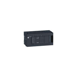
This product is part of the Modicon M241 range, an offer of logic controllers for performance demanding applications. This logic controller provides 24 discrete, 8 fast inputs, 16 transistor, 4 fast outputs with ethernet PNP transistor output. It is a Modicon logic controller with a rated supply/output voltage of 24V DC and an output current of 0.5A for transistor output, 0.1A for fast output current with sink or source input logic positive output logic. This product enables to build application intuitively as never before due to an organised screen design. Integrated connections are USB port with mini B USB 2.0, non isolated serial link 1 with RJ45 and RS232/RS485 interface, non isolated serial link 2 with removable screw terminal block and RS485 interface and ethernet with RJ45 . It is a Modicon M241 controller with 8MB for program, 64MB for system memory RAM, 128MB built-in flash memory for backup of user programs and a SD card memory capacity of 16GB. It is an IP20 rated product. Its dimensions are 190mm (Width) x 95mm (Depth) x 90mm (Height). It weighs 0.62kg. The Modicon M241 logic controllers are designed for high-performance compact machines incorporating speed and position control functions. This product is certified by CE, IACS E10, CSA, RCM and CULus. It meets ANSI/ISA 12-12-01, CSA C22.2 No 142, CSA C22.2 No 213, EN/IEC 61131-22007, marine specification (LR, ABS, DNV, GL), UL 1604 and UL 508 standards. It supports DIN rail mount. Achieve benchmark performance while increasing profitability with the Modicon M241 through intuitive machine programming with EcoStruxure Machine Expert, ready-to-use applications and function blocks.
Main
| Characteristic | Value(s) |
|---|---|
| Range of Product | Modicon M241 |
| Product or Component Type | Logic controller |
| [Us] rated supply voltage | 24 V DC |
| Discrete input number | 24, discrete input 8 fast input IEC 61131-2 Type 1 |
| Discrete output type | Transistor |
| Discrete output number | 16 transistor 4 fast output |
| Discrete output voltage | 24 V DC transistor output |
| Discrete output current | 0.1 A fast output (PTO mode) Q0...Q3) 0.5 A transistor output Q0...Q15) |
Complementary
| Characteristic | Value(s) |
|---|---|
| Discrete I/O number | 40 |
| Maximum number of I/O expansion module | 7 (local I/O-Architecture) 14 (remote I/O-Architecture) |
| Supply voltage limits | 20.4â¦28.8 V |
| Inrush current | 50 A |
| Power consumption in W | 32.6â¦40.4 W with max number of I/O expansion module) |
| Discrete input logic | Sink or source |
| Discrete input voltage | 24 V |
| Discrete input voltage type | DC |
| Voltage state 1 guaranteed | >= 15 V input |
| Voltage state 0 guaranteed | <= 5 V input |
| Discrete input current | 10.7 mA fast input 7 mA input |
| Input impedance | 4.7 kOhm input 2.81 kOhm fast input |
| Response time | <= 2 µs turn-on, I0...I7 fast input <= 2 µs turn-off, I0...I7 fast input <= 2 µs turn-on, Q0...Q3 fast output <= 2 µs turn-off, Q0...Q3 fast output 50 µs turn-on, I0...I15 input 50 µs turn-off, I0...I15 input <= 34 µs turn-on, Q0...Q15 output <= 250 µs turn-off, Q0...Q15 output |
| Configurable filtering time | 1 µs fast input 12 ms fast input 0 ms input 1 ms input 4 ms input 12 ms input |
| Discrete output logic | Positive logic (source) |
| Output voltage limits | 30 V DC |
| Maximum current per output common | 2 A |
| Maximum output frequency | 20 kHz fast output (PWM mode) 100 kHz fast output (PLS mode) 1 kHz output |
| Accuracy | +/- 0.1 % 0.02â¦0.1 kHz fast output +/- 1 % 0.1â¦1 kHz fast output |
| Maximum leakage current | 5 µA output |
| Maximum voltage drop | <1 V |
| Maximum tungsten load | <2.4 W |
| Protection type | Short-circuit protection Short-circuit and overload protection with automatic reset Reverse polarity protection fast output |
| Reset time | 10 ms automatic reset output 12 s automatic reset fast output |
| Memory capacity | 64 MB system memory RAM |
| Data backed up | 128 MB built-in flash memory backup of user programs |
| Data storage equipment | <= 16 GB SD card optional) |
| Battery type | BR2032 lithium non-rechargeable 4 year(s) |
| Backup time | 2 years 77 °F (25 °C) |
| Execution time for 1 KInstruction | 0.3 ms event and periodic task 0.7 ms other instruction |
| Application structure | 3 cyclic master tasks + 1 freewheeling task 8 external event tasks 4 cyclic master tasks 8 event tasks |
| Realtime clock | With |
| Clock drift | <= 60 s/month 77 °F (25 °C) |
| Positioning functions | PTO 4 100 kHz) PTO 4 transistor output 1 kHz) |
| Counting input number | 4 fast input (HSC mode) 200 kHz 16 standard input 1 kHz |
| Control signal type | A/B 100 kHz fast input (HSC mode) Pulse/direction 200 kHz fast input (HSC mode) Single phase 200 kHz fast input (HSC mode) |
| Integrated connection type | Non isolated serial link serial 1 RJ45 RS232/RS485 Non isolated serial link serial 2 removable screw terminal block RS485 USB port mini B USB 2.0 Ethernet RJ45 |
| Supply | Serial 1)serial link supply 5 V, <200 mA |
| Transmission rate | 1.2...115.2 kbit/s (115.2 kbit/s by default) 49.2 ft (15 m) RS485 1.2...115.2 kbit/s (115.2 kbit/s by default) 9.8 ft (3 m) RS232 480 Mbit/s 9.8 ft (3 m) USB 10/100 Mbit/s Ethernet |
| Communication port protocol | Non isolated serial link Modbus master/slave |
| Port Ethernet | 10BASE-T/100BASE-TX - 1 copper cable |
| ethernet services | FDR DHCP server via TM4 Ethernet switch network module DHCP client embedded Ethernet port SMS notifications Updating firmware SNMP client/server Programming NGVL Monitoring IEC VAR ACCESS FTP client/server Downloading SQL client Modbus TCP client I/O scanner Ethernet/IP originator I/O scanner embedded Ethernet port Ethernet/IP target, Modbus TCP server and Modbus TCP slave Send and receive email from the controller based on TCP/UDP library Web server (WebVisu & XWeb system) OPC UA server DNS client |
| Local signalling | 1 LED (green) for PWR 1 LED (green) for RUN 1 LED (red) for module error (ERR) 1 LED (red) for I/O error (I/O) 1 LED (green) for SD card access (SD) 1 LED (red) for BAT 1 LED (green) for SL1 1 LED (green) for SL2 1 LED (red) for bus fault on TM4 (TM4) 1 LED per channel (green) for I/O state 1 LED (green) for Ethernet port activity |
| Electrical connection | removable screw terminal block for inputs and outputs pitch 5.08 mm) removable screw terminal block for connecting the 24 V DC power supply pitch 5.08 mm) |
| Maximum cable distance between devices | Unshielded cable <164.04 ft (50 m) input Shielded cable <32.8 ft (10 m) fast input Unshielded cable <164.04 ft (50 m) output Shielded cable <9.8 ft (3 m) fast output |
| Insulation | Between supply and internal logic 500 V AC Non-insulated between supply and ground Between input and internal logic 500 V AC Non-insulated between inputs Between fast input and internal logic 500 V AC Between output and internal logic 500 V AC Non-insulated between outputs Between fast output and internal logic 500 V AC Between output groups 500 V AC |
| Marking | CE |
| Surge withstand | 1 kV power lines (DC) common mode IEC 61000-4-5 1 kV shielded cable common mode IEC 61000-4-5 0.5 kV power lines (DC) differential mode IEC 61000-4-5 1 kV relay output differential mode IEC 61000-4-5 1 kV input common mode IEC 61000-4-5 1 kV transistor output common mode IEC 61000-4-5 |
| Web services | Web server |
| Maximum number of connections | 8 Modbus server 8 SoMachine protocol 10 web server 4 FTP server 16 Ethernet/IP target 8 Modbus client |
| Number of server device(s) | 64 Modbus TCP 16 EtherNet/IP |
| Cycle time | 10 ms 16 EtherNet/IP 64 ms 64 Modbus TCP |
| Mounting support | Top hat type TH35-15 rail IEC 60715 Top hat type TH35-7.5 rail IEC 60715 plate or panel with fixing kit |
| Height | 3.5 in (90 mm) |
| Depth | 3.7 in (95 mm) |
| Width | 7.5 in (190 mm) |
| Product Weight | 1.37 lb(US) (0.62 kg) |

controller M241 24 IO transistor PNP Ethernet CAN master

controller M241 40 IO transistor NPN Ethernet
controller M241 40 IO transistor NPN

compact base M238 - 24 I/O - 24 V DC Supply - CANOpen - internal RAM 1000 kB