
 1 year warranty

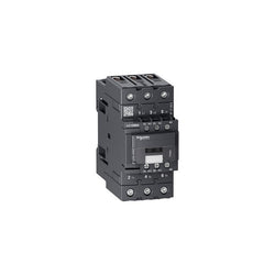
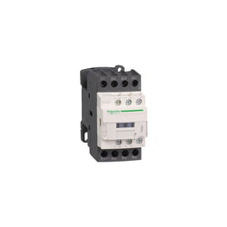
TeSys Deca contactor, 4 poles (4NO), for non-inductive load applications up to 60A/440V AC-1. They can be used to create motor starters for almost any type of application. It provides a 24V 50/60Hz AC coil, 1NO+1NC built-in auxiliary contacts (NC mirror contact), power connection by EverLink BTR screw connectors and control by screw clamp terminals. For operating rates until 3600 cycles/hour and environments until 60°C, it procures high reliability and durability. Compact (70mm width), DIN-rail mounting or screw fixing. Power contacts have a 60A resistive load rating. Multi standards certified (IEC, UL, CSA, CCC, EAC, Marine). Contactor has one normally open and one normally closed auxiliary contact built-in as standard. The NC contact is mirror certified. Screw clamp terminals are used for load and auxiliary connections. An extensive line of accessories makes it easy to meet the requirements of most applications. The contactor is 4.80 inches tall, 2.76 inches wide and 4.72 inches deep. It weighs 2.40 lbs. Contactor is certified to UL, CSA, IEC, CCC, EAC and Marine standards.
Main
| Characteristic | Value(s) |
|---|---|
| Range | TeSys TeSys Deca |
| Range of Product | TeSys Deca |
| Product or Component Type | Contactor |
| Device short name | LC1D |
| Contactor application | Resistive load |
| Utilisation category | AC-1 |
| Poles description | 4P |
| [Ue] rated operational voltage | Power circuit <= 690 V AC 25...400 Hz Power circuit <= 300 V DC |
| [Ie] rated operational current | 60 A (at <140 °F (60 °C)) at <= 440 V AC AC-1 for power circuit |
| [Uc] control circuit voltage | 24 V AC 50/60 Hz |
Complementary
| Characteristic | Value(s) |
|---|---|
| Compatibility code | LC1D |
| Pole contact composition | 4 NO |
| Protective cover | With |
| [Ith] conventional free air thermal current | 10 A (at 140 °F (60 °C)) for signalling circuit 60 A (at 140 °F (60 °C)) for power circuit |
| Irms rated making capacity | 140 A AC for signalling circuit conforming to IEC 60947-5-1 250 A DC for signalling circuit conforming to IEC 60947-5-1 800 A at 440 V for power circuit conforming to IEC 60947 |
| Rated breaking capacity | 800 A at 440 V for power circuit conforming to IEC 60947 |
| [Icw] rated short-time withstand current | 320 A 104 °F (40 °C) - 10 s for power circuit 720 A 104 °F (40 °C) - 1 s for power circuit 72 A 104 °F (40 °C) - 10 min for power circuit 165 A 104 °F (40 °C) - 1 min for power circuit 100 A - 1 s for signalling circuit 120 A - 500 ms for signalling circuit 140 A - 100 ms for signalling circuit |
| Associated fuse rating | 10 A gG for signalling circuit conforming to IEC 60947-5-1 80 A gG at <= 690 V coordination type 1 for power circuit 80 A gG at <= 690 V coordination type 2 for power circuit |
| Average impedance | 1.6 mOhm - Ith 60 A 50 Hz for power circuit |
| Power dissipation per pole | 5.8 W AC-1 |
| [Ui] rated insulation voltage | Power circuit 600 V CSA Power circuit 600 V UL Signalling circuit 690 V IEC 60947-1 Signalling circuit 600 V CSA Signalling circuit 600 V UL Power circuit 690 V IEC 60947-4-1 |
| Overvoltage category | III |
| pollution degree | 3 |
| [Uimp] rated impulse withstand voltage | 6 kV IEC 60947 |
| Safety reliability level | B10d = 1369863 cycles contactor with nominal load EN/ISO 13849-1 B10d = 20000000 cycles contactor with mechanical load EN/ISO 13849-1 |
| Mechanical durability | 6 Mcycles |
| Electrical durability | 1.4 Mcycles 60 A AC-1 <= 440 V |
| Control circuit type | AC 50/60 Hz |
| Coil technology | Without built-in suppressor module |
| Control circuit voltage limits | 0.3...0.6 Uc (-40â¦158 °F (-40â¦70 °C)):drop-out AC 50/60 Hz 0.8...1.1 Uc (-40â¦140 °F (-40â¦60 °C)):operational AC 50 Hz 0.85...1.1 Uc (-40â¦140 °F (-40â¦60 °C)):operational AC 60 Hz 1...1.1 Uc (140â¦158 °F (60â¦70 °C)):operational AC 50/60 Hz |
| Inrush power in VA | 140 VA 60 Hz cos phi 0.75 (at 68 °F (20 °C)) 160 VA 50 Hz cos phi 0.75 (at 68 °F (20 °C)) |
| Hold-in power consumption in VA | 13 VA 60 Hz cos phi 0.3 (at 68 °F (20 °C)) 15 VA 50 Hz cos phi 0.3 (at 68 °F (20 °C)) |
| Heat dissipation | 4â¦5 W at 50/60 Hz |
| Operating time | 4...19 ms opening 12...26 ms closing |
| Maximum operating rate | 3600 cyc/h at 60 °C |
| Connections - terminals | Control circuit: screw clamp terminals 2 0.002â¦0.004 in² (1â¦2.5 mm²) - cable stiffness: flexible with cable end Control circuit: screw clamp terminals 1 0.002â¦0.006 in² (1â¦4 mm²) - cable stiffness: flexible without cable end Control circuit: screw clamp terminals 2 0.002â¦0.006 in² (1â¦4 mm²) - cable stiffness: flexible without cable end Control circuit: screw clamp terminals 1 0.002â¦0.006 in² (1â¦4 mm²) - cable stiffness: flexible with cable end Control circuit: screw clamp terminals 1 0.002â¦0.006 in² (1â¦4 mm²) - cable stiffness: solid without cable end Control circuit: screw clamp terminals 2 0.002â¦0.006 in² (1â¦4 mm²) - cable stiffness: solid without cable end Power circuit: EverLink BTR screw connectors 1 0.002â¦0.05 in² (1â¦35 mm²) - cable stiffness: flexible without cable end Power circuit: EverLink BTR screw connectors 2 0.002â¦0.04 in² (1â¦25 mm²) - cable stiffness: flexible without cable end Power circuit: EverLink BTR screw connectors 1 0.002â¦0.05 in² (1â¦35 mm²) - cable stiffness: flexible with cable end Power circuit: EverLink BTR screw connectors 2 0.002â¦0.04 in² (1â¦25 mm²) - cable stiffness: flexible with cable end Power circuit: EverLink BTR screw connectors 1 0.002â¦0.05 in² (1â¦35 mm²) - cable stiffness: solid without cable end Power circuit: EverLink BTR screw connectors 2 0.002â¦0.04 in² (1â¦25 mm²) - cable stiffness: solid without cable end |
| Tightening torque | Control circuit 15.05 lbf.in (1.7 N.m) EverLink BTR screw connectors flat à 6 mm Control circuit 15.05 lbf.in (1.7 N.m) EverLink BTR screw connectors Philips No 2 Power circuit 70.8 lbf.in (8 N.m) EverLink BTR screw connectors 0.04â¦0.05 in² (25â¦35 mm²) hexagonal 0.2 in (4 mm) Power circuit 44.3 lbf.in (5 N.m) EverLink BTR screw connectors 0.002â¦0.04 in² (1â¦25 mm²) hexagonal 0.2 in (4 mm) Control circuit 15.05 lbf.in (1.7 N.m) EverLink BTR screw connectors pozidriv No 2 Power circuit 22.1 lbf.in (2.5 N.m) EverLink BTR screw connectors pozidriv No 2 |
| Auxiliary contact composition | 1 NO + 1 NC |
| Auxiliary contacts type | Mechanically linked 1 NO + 1 NC IEC 60947-5-1 Mirror contact 1 NC IEC 60947-4-1 |
| Signalling circuit frequency | 25...400 Hz |
| Minimum switching voltage | 17 V for signalling circuit |
| Minimum switching current | 5 mA for signalling circuit |
| Insulation resistance | > 10 MOhm for signalling circuit |
| Non-overlap time | 1.5 ms on de-energisation between NC and NO contact 1.5 ms on energisation between NC and NO contact |
| Mounting Support | Rail Plate |
TeSys Deca contactor, 4 poles (4NO), for non-inductive load applications up to 80A/440V AC-1. They can be used to create motor starters for almost any type of application. It provides a 48V 50/60Hz AC coil, 1NO+1NC built-in auxiliary contacts (NC mirror certified), power connection by EverLink BTR screw connectors, control connection by screw clamp terminals. For operating rates until 3600 cycles/hour and environments until 60°C, it procures high reliability and durability. Compact (70mm width), DIN-rail mounting or screw fixing. Power contacts have a 80A resistive load rating. Multi standards certified (IEC, UL, CSA, CCC, EAC, Marine). Contactor has one normally open and one normally closed auxiliary contact built-in as standard. The NC contact is mirror certified. Screw clamp terminals are used for load and auxiliary connections. An extensive line of accessories makes it easy to meet the requirements of most applications. The contactor is 4.80 inches tall, 2.76 inches wide and 4.72 inches deep. It weighs 2.54 lbs. Contactor is certified to UL, CSA, IEC, CCC, EAC and Marine standards.
Main
| Characteristic | Value(s) |
|---|---|
| Range | TeSys TeSys Deca |
| Range of Product | TeSys Deca |
| Product or Component Type | Contactor |
| Device short name | LC1D |
| Contactor application | Resistive load |
| Utilisation category | AC-1 |
| Poles description | 4P |
| [Ue] rated operational voltage | Power circuit <= 690 V AC 25...400 Hz Power circuit <= 300 V DC |
| [Ie] rated operational current | 80 A (at <140 °F (60 °C)) at <= 440 V AC AC-1 for power circuit |
| [Uc] control circuit voltage | 48 V AC 50/60 Hz |
Complementary
| Characteristic | Value(s) |
|---|---|
| Compatibility code | LC1D |
| Pole contact composition | 4 NO |
| Protective cover | With |
| [Ith] conventional free air thermal current | 10 A (at 140 °F (60 °C)) for signalling circuit 80 A (at 140 °F (60 °C)) for power circuit |
| Irms rated making capacity | 140 A AC for signalling circuit conforming to IEC 60947-5-1 250 A DC for signalling circuit conforming to IEC 60947-5-1 1000 A at 440 V for power circuit conforming to IEC 60947 |
| Rated breaking capacity | 1000 A at 440 V for power circuit conforming to IEC 60947 |
| [Icw] rated short-time withstand current | 640 A 104 °F (40 °C) - 10 s for power circuit 900 A 104 °F (40 °C) - 1 s for power circuit 110 A 104 °F (40 °C) - 10 min for power circuit 260 A 104 °F (40 °C) - 1 min for power circuit 100 A - 1 s for signalling circuit 120 A - 500 ms for signalling circuit 140 A - 100 ms for signalling circuit |
| Associated fuse rating | 10 A gG for signalling circuit conforming to IEC 60947-5-1 125 A gG at <= 690 V coordination type 1 for power circuit 125 A gG at <= 690 V coordination type 2 for power circuit |
| Average impedance | 1.6 mOhm - Ith 80 A 50 Hz for power circuit |
| Power dissipation per pole | 10.2 W AC-1 |
| [Ui] rated insulation voltage | Power circuit 600 V CSA Power circuit 600 V UL Signalling circuit 690 V IEC 60947-1 Signalling circuit 600 V CSA Signalling circuit 600 V UL Power circuit 690 V IEC 60947-4-1 |
| Overvoltage category | III |
| pollution degree | 3 |
| [Uimp] rated impulse withstand voltage | 6 kV IEC 60947 |
| Safety reliability level | B10d = 1369863 cycles contactor with nominal load EN/ISO 13849-1 B10d = 20000000 cycles contactor with mechanical load EN/ISO 13849-1 |
| Mechanical durability | 6 Mcycles |
| Electrical durability | 1.4 Mcycles 80 A AC-1 <= 440 V |
| Control circuit type | AC 50/60 Hz |
| Coil technology | Without built-in suppressor module |
| Control circuit voltage limits | 0.3...0.6 Uc (-40â¦158 °F (-40â¦70 °C)):drop-out AC 50/60 Hz 0.8...1.1 Uc (-40â¦140 °F (-40â¦60 °C)):operational AC 50 Hz 0.85...1.1 Uc (-40â¦140 °F (-40â¦60 °C)):operational AC 60 Hz 1...1.1 Uc (140â¦158 °F (60â¦70 °C)):operational AC 50/60 Hz |
| Inrush power in VA | 140 VA 60 Hz cos phi 0.75 (at 68 °F (20 °C)) 160 VA 50 Hz cos phi 0.75 (at 68 °F (20 °C)) |
| Hold-in power consumption in VA | 13 VA 60 Hz cos phi 0.3 (at 68 °F (20 °C)) 15 VA 50 Hz cos phi 0.3 (at 68 °F (20 °C)) |
| Heat dissipation | 4â¦5 W at 50/60 Hz |
| Operating time | 4...19 ms opening 12...26 ms closing |
| Maximum operating rate | 3600 cyc/h at 60 °C |
| Connections - terminals | Control circuit: screw clamp terminals 2 0.002â¦0.004 in² (1â¦2.5 mm²) - cable stiffness: flexible with cable end Control circuit: screw clamp terminals 1 0.002â¦0.006 in² (1â¦4 mm²) - cable stiffness: flexible without cable end Control circuit: screw clamp terminals 2 0.002â¦0.006 in² (1â¦4 mm²) - cable stiffness: flexible without cable end Control circuit: screw clamp terminals 1 0.002â¦0.006 in² (1â¦4 mm²) - cable stiffness: flexible with cable end Control circuit: screw clamp terminals 1 0.002â¦0.006 in² (1â¦4 mm²) - cable stiffness: solid without cable end Control circuit: screw clamp terminals 2 0.002â¦0.006 in² (1â¦4 mm²) - cable stiffness: solid without cable end Power circuit: EverLink BTR screw connectors 1 0.002â¦0.05 in² (1â¦35 mm²) - cable stiffness: flexible without cable end Power circuit: EverLink BTR screw connectors 2 0.002â¦0.04 in² (1â¦25 mm²) - cable stiffness: flexible without cable end Power circuit: EverLink BTR screw connectors 1 0.002â¦0.05 in² (1â¦35 mm²) - cable stiffness: flexible with cable end Power circuit: EverLink BTR screw connectors 2 0.002â¦0.04 in² (1â¦25 mm²) - cable stiffness: flexible with cable end Power circuit: EverLink BTR screw connectors 1 0.002â¦0.05 in² (1â¦35 mm²) - cable stiffness: solid without cable end Power circuit: EverLink BTR screw connectors 2 0.002â¦0.04 in² (1â¦25 mm²) - cable stiffness: solid without cable end |
| Tightening torque | Control circuit 15.05 lbf.in (1.7 N.m) screw clamp terminals flat à 6 mm Control circuit 15.05 lbf.in (1.7 N.m) screw clamp terminals Philips No 2 Power circuit 70.8 lbf.in (8 N.m) screw clamp terminals 0.04â¦0.05 in² (25â¦35 mm²) hexagonal 0.2 in (4 mm) Power circuit 44.3 lbf.in (5 N.m) screw clamp terminals 0.002â¦0.04 in² (1â¦25 mm²) hexagonal 0.2 in (4 mm) Control circuit 15.05 lbf.in (1.7 N.m) screw clamp terminals pozidriv No 2 Power circuit 22.1 lbf.in (2.5 N.m) screw clamp terminals pozidriv No 2 |
| Auxiliary contact composition | 1 NO + 1 NC |
| Auxiliary contacts type | Mechanically linked 1 NO + 1 NC IEC 60947-5-1 Mirror contact 1 NC IEC 60947-4-1 |
| Signalling circuit frequency | 25...400 Hz |
| Minimum switching voltage | 17 V for signalling circuit |
| Minimum switching current | 5 mA for signalling circuit |
| Insulation resistance | > 10 MOhm for signalling circuit |
| Non-overlap time | 1.5 ms on de-energisation between NC and NO contact 1.5 ms on energisation between NC and NO contact |
| Mounting Support | Plate Rail |

TeSys D contactor - 4P(4 NO) - AC-1 - <= 440 V 32 A - 110 V AC 50/60 Hz coil
TeSys D contactor - 3P(3 NO) - AC-3 - <= 440 V 18 A - 380 V AC coil

Capacitor contactor, TeSys D, 63 kVAR at 400 V/50 Hz, coil 230 V AC 50/60 Hz
Main
| Characteristic | Value(s) |
|---|---|
| Range | TeSys |
| Range of Product | TeSys F |
| Product or Component Type | Contactor |
| Device short name | LC1F |
| Contactor application | Resistive load Motor control |
| Utilisation category | AC-4 AC-3 AC-1 |
| Poles description | 3P |
| [Ue] rated operational voltage | <= 690 V AC 50/60 Hz <= 460 V DC |
| [Uc] control circuit voltage | 220 V AC 50 Hz |
| [Ie] rated operational current | 200 A (at <104 °F (40 °C)) at <= 440 V AC-1 115 A (at <131 °F (55 °C)) at <= 440 V AC-3 |
Complementary
| Characteristic | Value(s) |
|---|---|
| [Uimp] rated impulse withstand voltage | 8 kV |
| [Ith] conventional free air thermal current | 200 A (at 104 °F (40 °C)) |
| Rated breaking capacity | 920 A conforming to IEC 60947-4-1 |
| [Icw] rated short-time withstand current | 1100 A 104 °F (40 °C) - 10 s 640 A 104 °F (40 °C) - 30 s 520 A 104 °F (40 °C) - 1 min 400 A 104 °F (40 °C) - 3 min 320 A 104 °F (40 °C) - 10 min |
| Associated fuse rating | 125 A aM at <= 440 V 200 A gG at <= 440 V |
| Average impedance | 0.37 mOhm - Ith 200 A 50 Hz |
| [Ui] rated insulation voltage | 1000 V IEC 60947-4-1 1500 V VDE 0110 group C |
| Power dissipation per pole | 15 W AC-1 5 W AC-3 |
| Overvoltage category | III |
| power pole contact composition | 3 NO |
| Motor power kW | 55 kW at 380...400 V AC 50/60 Hz (AC-3) 59 kW at 415 V AC 50/60 Hz (AC-3) 59 kW at 440 V AC 50/60 Hz (AC-3) 75 kW at 500 V AC 50/60 Hz (AC-3) 80 kW at 660...690 V AC 50/60 Hz (AC-3) 30 kW at 220...230 V AC 50/60 Hz (AC-3) 18.5 kW at 400 V AC 50/60 Hz (AC-4) |
| Control circuit voltage limits | Operational 0.85...1.1 Uc 50/60 Hz 131 °F (55 °C)) Drop-out 0.35...0.55 Uc 50/60 Hz 131 °F (55 °C)) |
| Mechanical durability | 10 Mcycles |
| Inrush power in VA | 550 VA, 50 Hz 0.3 68 °F (20 °C)) |
| Hold-in power consumption in VA | 45 VA, 50 Hz 0.3 68 °F (20 °C)) |
| Maximum operating rate | 2400 cyc/h 131 °F (55 °C) |
| Operating time | 23...35 ms closing 5...15 ms opening |
| Connections - terminals | Power circuit bar 2 20 x 3 mm Power circuit lugs-ring terminals 1 0.1 in² (95 mm²) Power circuit connector 1 0.1 in² (95 mm²) Control circuit screw clamp terminals 1 0.002â¦0.006 in² (1â¦4 mm²)flexible without cable end Control circuit screw clamp terminals 2 0.002â¦0.006 in² (1â¦4 mm²)flexible without cable end Control circuit screw clamp terminals 1 0.002â¦0.006 in² (1â¦4 mm²)flexible with cable end Control circuit screw clamp terminals 2 0.002â¦0.004 in² (1â¦2.5 mm²)flexible with cable end Control circuit screw clamp terminals 1 0.002â¦0.006 in² (1â¦4 mm²)solid without cable end Control circuit screw clamp terminals 2 0.002â¦0.006 in² (1â¦4 mm²)solid without cable end Power circuit bolted connection |
| Tightening torque | Power circuit 88.5 lbf.in (10 N.m) Control circuit 10.6 lbf.in (1.2 N.m) |
| Mounting Support | Plate |
| Heat dissipation | 12â¦16 W |
| Standards | EN 60947-4-1 IEC 60947-1 JIS C8201-4-1 EN 60947-1 IEC 60947-4-1 |
| Product Certifications | RINA BV RMRoS ABS CB CCC UL DNV LROS (Lloyds register of shipping) |
| Compatibility code | LC1F |
| Control circuit type | AC 50 Hz |


TeSys K contactor - 3P - AC-3 <= 440 V 6 A - 1 NC aux. - 110 V DC low

PLC Direct is not an authorized distributor. We offer a broad range of in-stock products with minimal lead time.

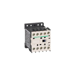
TeSys K contactor, 3 poles (3NO), for motor control applications up to 9A/690V AC-3 (4kW@400V), and for non-inductive load control applications up to 20A/690V AC-1. It provides a 440V 50/60Hz AC coil, 1NO built-in auxiliary contact, connection by screw clamp terminals. For operating rates until 600 cycles/hour and environments until 50°C, it procures reliability and durability to standard applications. Very compact (45mm width), DIN-rail mounting or screw fixing. Multi standards certified (IEC, UL, CSA, CCC, EAC), Green Premium compliant (RoHS/REACh).
Main
| Characteristic | Value(s) |
|---|---|
| Range | TeSys |
| Product or Component Type | Contactor |
| Device Application | Control |
| Contactor application | Motor control Resistive load |
Complementary
| Characteristic | Value(s) |
|---|---|
| Utilisation category | AC-3 AC-3e AC-1 AC-4 |
| Poles description | 3P |
| power pole contact composition | 3 NO |
| [Ue] rated operational voltage | Power circuit <= 690 V AC <= 400 Hz Signalling circuit <= 690 V AC <= 400 Hz |
| [Ie] rated operational current | 9 A (at <140 °F (60 °C)) at <= 440 V AC AC-3 for power circuit 9 A (at <140 °F (60 °C)) at <= 440 V AC AC-3e for power circuit 20 A (at <140 °F (60 °C)) at <= 690 V AC AC-1 for power circuit |
| Control circuit type | AC 50/60 Hz |
| [Uc] control circuit voltage | 440 V AC 50/60 Hz |
| Motor power kW | 2.2 kW 220...230 V AC 50/60 Hz AC-3 4 kW 380...415 V AC 50/60 Hz AC-3 4 kW 440/690 V AC 50/60 Hz AC-3 2.2 kW 220...230 V AC 50/60 Hz AC-3e 4 kW 380...415 V AC 50/60 Hz AC-3e 4 kW 440/690 V AC 50/60 Hz AC-3e 2.2 kW 220...230 V AC 50/60 Hz AC-4 4 kW 380...415 V AC 50/60 Hz AC-4 4 kW 440/690 V AC 50/60 Hz AC-4 |
| Auxiliary contact composition | 1 NO |
| [Uimp] rated impulse withstand voltage | 8 kV |
| Overvoltage category | III |
| [Ith] conventional free air thermal current | 20 A (at 140 °F (60 °C)) for power circuit 10 A (at 122 °F (50 °C)) for signalling circuit |
| Irms rated making capacity | 110 A AC for power circuit conforming to IEC 60947 110 A AC for signalling circuit conforming to IEC 60947 |
| Rated breaking capacity | 110 A at 220...230 V conforming to IEC 60947 110 A at 380...400 V conforming to IEC 60947 110 A at 415 V conforming to IEC 60947 110 A at 440 V conforming to IEC 60947 80 A at 500 V conforming to IEC 60947 70 A at 660...690 V conforming to IEC 60947 |
| [Icw] rated short-time withstand current | 90 A 122 °F (50 °C) - 1 s for power circuit 85 A 122 °F (50 °C) - 5 s for power circuit 80 A 122 °F (50 °C) - 10 s for power circuit 60 A 122 °F (50 °C) - 30 s for power circuit 45 A 122 °F (50 °C) - 1 min for power circuit 40 A 122 °F (50 °C) - 3 min for power circuit 20 A 122 °F (50 °C) - >= 15 min for power circuit 80 A - 1 s for signalling circuit 90 A - 500 ms for signalling circuit 110 A - 100 ms for signalling circuit |
| Associated fuse rating | 25 A gG at <= 440 V for power circuit 25 A aM for power circuit 10 A gG for signalling circuit conforming to IEC 60947 10 A gG for signalling circuit conforming to VDE 0660 |
| Average impedance | 3 mOhm - Ith 20 A 50 Hz for power circuit |
| Insulation resistance | > 10 MOhm for signalling circuit |
| Inrush power in VA | 30 VA (at 68 °F (20 °C)) |
| Hold-in power consumption in VA | 4.5 VA (at 68 °F (20 °C)) |
| Heat dissipation | 1.3 W |
| Control circuit voltage limits | Operational: 0.8...1.15 Uc (at <122 °F (50 °C)) Drop-out: >= 0.20 Uc (at <122 °F (50 °C)) |
| Connections - terminals | screw clamp terminals 1 0.002â¦0.006 in² (1.5â¦4 mm²)solid screw clamp terminals 1 0.001â¦0.006 in² (0.75â¦4 mm²)flexible without cable end screw clamp terminals 1 0.0005â¦0.004 in² (0.34â¦2.5 mm²)flexible with cable end screw clamp terminals 2 0.002â¦0.006 in² (1.5â¦4 mm²)solid screw clamp terminals 2 0.001â¦0.006 in² (0.75â¦4 mm²)flexible without cable end screw clamp terminals 2 0.0005â¦0.002 in² (0.34â¦1.5 mm²)flexible with cable end |
| Maximum operating rate | 3600 cyc/h |
| Auxiliary contacts type | Instantaneous 1 NO |
| Signalling circuit frequency | <= 400 Hz |
| Minimum switching current | 5 mA for signalling circuit |
| Minimum switching voltage | 17 V for signalling circuit |
| Operating time | 10...20 ms coil de-energisation and NO opening 10...20 ms coil energisation and NO closing |
| Safety reliability level | B10d = 1369863 cycles contactor with nominal load EN/ISO 13849-1 B10d = 20000000 cycles contactor with mechanical load EN/ISO 13849-1 |
| Non overlap distance | 0.02 in (0.5 mm) |
| Mechanical durability | 10 Mcycles |
| Electrical durability | 1.3 Mcycles 9 A AC-3 <= 440 V 1.3 Mcycles 9 A AC-3e <= 440 V 0.16 Mcycles 20 A AC-1 <= 690 V 0.02 Mcycles 54 A AC-4 <= 440 V |
| Mechanical robustness | Shocks contactor closed, on X axis10 Gn for 11 ms IEC 60068-2-27 Shocks contactor closed, on Y axis15 Gn for 11 ms IEC 60068-2-27 Shocks contactor closed, on Z axis15 Gn for 11 ms IEC 60068-2-27 Shocks contactor opened, on X axis6 Gn for 11 ms IEC 60068-2-27 Shocks contactor opened, on Y axis10 Gn for 11 ms IEC 60068-2-27 Shocks contactor opened, on Z axis10 Gn for 11 ms IEC 60068-2-27 Vibrations contactor closed4 Gn, 5...300 Hz IEC 60068-2-6 Vibrations contactor opened2 Gn, 5...300 Hz IEC 60068-2-6 |
| Height | 2.3 in (58 mm) |
| Width | 1.8 in (45 mm) |
| Depth | 2.2 in (57 mm) |
TeSys K contactor - 3P - AC-3 <= 440 V 6 A - 1 NO aux. - 24 V DC low
Capacitor contactor, TeSys D, 40 kVAR at 400 V/50 Hz, coil 230 V AC 50/60 Hz
TeSys D contactor 3P 66A AC-3 up to 440V coil 440V AC 50/60Hz
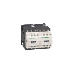
TeSys Deca reversing contactor, 3 poles (3NO), for motor control applications up to 32A/690V AC-3 (15kW@400V). It provides 48V DC coils with transient suppressor module, 2NO+2NC built-in auxiliary contacts (NC mirror contacts), connection by screw clamp terminals. For operating rates until 3600 cycles/hour and environments until 60°C, it procures high reliability and durability. Compact (90mm width), DIN-rail mounting or screw fixing. With pre-wired reversing power connections, mechanical interlock (without electrical interlocking). Multi standards certified (IEC, UL, CSA, CCC, EAC, Marine), Green Premium compliant (RoHS/REACh).
Main
| Characteristic | Value(s) |
|---|---|
| Range | TeSys |
| product name | TeSys Deca |
| Product or Component Type | Reversing contactor |
| Device short name | LC2D |
| Contactor application | Resistive load Motor control |
| Utilisation category | AC-3 AC-1 |
| Device presentation | Preassembled with reversing power busbar |
| Poles description | 3P |
| power pole contact composition | 3 NO |
| [Ue] rated operational voltage | Power circuit <= 690 V AC 25...400 Hz Power circuit <= 300 V DC |
| [Ie] rated operational current | 32 A (at <140 °F (60 °C)) at <= 440 V AC AC-3 for power circuit 50 A (at <140 °F (60 °C)) at <= 440 V AC AC-1 for power circuit |
| Motor power kW | 7.5 kW at 220...230 V AC 50 Hz 15 kW at 380...400 V AC 50 Hz 15 kW at 415...440 V AC 50 Hz 18.5 kW at 500 V AC 50 Hz 18.5 kW at 660...690 V AC 50 Hz |
| motor power HP (UL / CSA) | 2 hp at 115 V AC 60 Hz for 1 phase motors 5 hp at 230/240 V AC 60 Hz for 1 phase motors 7.5 hp at 200/208 V AC 60 Hz for 3 phase motors 10 hp at 230/240 V AC 60 Hz for 3 phase motors 20 hp at 460/480 V AC 60 Hz for 3 phase motors 30 hp at 575/600 V AC 60 Hz for 3 phase motors |
| Control circuit type | DC standard |
| [Uc] control circuit voltage | 48 V DC |
| Auxiliary contact composition | 1 NO + 1 NC |
| [Uimp] rated impulse withstand voltage | 6 kV IEC 60947 |
| Overvoltage category | III |
| [Ith] conventional free air thermal current | 10 A (at 140 °F (60 °C)) for signalling circuit 50 A (at 140 °F (60 °C)) for power circuit |
| Irms rated making capacity | 140 A AC for signalling circuit conforming to IEC 60947-5-1 250 A DC for signalling circuit conforming to IEC 60947-5-1 550 A at 440 V for power circuit conforming to IEC 60947 |
| Rated breaking capacity | 550 A at 440 V for power circuit conforming to IEC 60947 |
| [Icw] rated short-time withstand current | 60 A 104 °F (40 °C) - 10 min for power circuit 138 A 104 °F (40 °C) - 1 min for power circuit 260 A 104 °F (40 °C) - 10 s for power circuit 430 A 104 °F (40 °C) - 1 s for power circuit 100 A - 1 s for signalling circuit 120 A - 500 ms for signalling circuit 140 A - 100 ms for signalling circuit |
| Associated fuse rating | 10 A gG for signalling circuit conforming to IEC 60947-5-1 63 A gG at <= 690 V coordination type 1 for power circuit 63 A gG at <= 690 V coordination type 2 for power circuit |
| Average impedance | 2 mOhm - Ith 50 A 50 Hz for power circuit |
| [Ui] rated insulation voltage | Power circuit 690 V IEC 60947-4-1 Power circuit 600 V CSA Power circuit 600 V UL Signalling circuit 690 V IEC 60947-1 Signalling circuit 600 V CSA Signalling circuit 600 V UL |
| Electrical durability | 1.65 Mcycles 32 A AC-3 <= 440 V 1.4 Mcycles 50 A AC-1 <= 440 V |
| Power dissipation per pole | 2 W AC-3 5 W AC-1 |
| Front cover | With |
| Interlocking type | Mechanical |
| Mounting Support | Plate Rail |
| Standards | CSA C22.2 No 14 EN 60947-4-1 EN 60947-5-1 IEC 60947-4-1 IEC 60947-5-1 UL 508 |
| Product Certifications | DNV RINA CCC CSA GL BV GOST UL LROS (Lloyds register of shipping) |
| Connections - terminals | Control circuit screw clamp terminals 1 0.002â¦0.006 in² (1â¦4 mm²)flexible without cable end Control circuit screw clamp terminals 2 0.002â¦0.006 in² (1â¦4 mm²)flexible without cable end Control circuit screw clamp terminals 1 0.002â¦0.006 in² (1â¦4 mm²)flexible with cable end Control circuit screw clamp terminals 2 0.002â¦0.004 in² (1â¦2.5 mm²)flexible with cable end Control circuit screw clamp terminals 1 0.002â¦0.006 in² (1â¦4 mm²)solid Control circuit screw clamp terminals 2 0.002â¦0.006 in² (1â¦4 mm²)solid Power circuit screw clamp terminals 1 0.004â¦0.02 in² (2.5â¦10 mm²)flexible without cable end Power circuit screw clamp terminals 2 0.004â¦0.02 in² (2.5â¦10 mm²)flexible without cable end Power circuit screw clamp terminals 1 0.002â¦0.02 in² (1â¦10 mm²)flexible with cable end Power circuit screw clamp terminals 2 0.002â¦0.009 in² (1.5â¦6 mm²)flexible with cable end Power circuit screw clamp terminals 1 0.002â¦0.02 in² (1.5â¦10 mm²)solid Power circuit screw clamp terminals 2 0.004â¦0.02 in² (2.5â¦10 mm²)solid |
| Tightening torque | Control circuit 15.05 lbf.in (1.7 N.m) screw clamp terminals flat à 6 mm Control circuit 15.05 lbf.in (1.7 N.m) screw clamp terminals Philips No 2 Power circuit 22.1 lbf.in (2.5 N.m) screw clamp terminals flat à 6 mm Power circuit 22.1 lbf.in (2.5 N.m) screw clamp terminals Philips No 2 |
| Operating time | 53.55...72.45 ms closing 16...24 ms opening |
| Safety reliability level | B10d = 1369863 cycles contactor with nominal load EN/ISO 13849-1 B10d = 20000000 cycles contactor with mechanical load EN/ISO 13849-1 |
| Mechanical durability | 30 Mcycles |
| Maximum operating rate | 3600 cyc/h 140 °F (60 °C) |
Complementary
| Characteristic | Value(s) |
|---|---|
| Coil technology | Built-in bidirectional peak limiting diode suppressor |
| Control circuit voltage limits | 0.1...0.25 Uc (-40â¦158 °F (-40â¦70 °C)):drop-out DC 0.7...1.25 Uc (-40â¦140 °F (-40â¦60 °C)):operational DC 1...1.25 Uc (140â¦158 °F (60â¦70 °C)):operational DC |
| Time constant | 28 ms |
| Inrush power in W | 5.4 W 68 °F (20 °C)) |
| Hold-in power consumption in W | 5.4 W 68 °F (20 °C) |
| Auxiliary contacts type | Mechanically linked 1 NO + 1 NC IEC 60947-5-1 Mirror contact 1 NC IEC 60947-4-1 |
| Signalling circuit frequency | 25...400 Hz |
| Minimum switching current | 5 mA for signalling circuit |
| Minimum switching voltage | 17 V for signalling circuit |
| Non-overlap time | 1.5 ms on de-energisation between NC and NO contact 1.5 ms on energisation between NC and NO contact |
| Insulation resistance | > 10 MOhm for signalling circuit |

TeSys D reversing contactor, 3 poles (3NO), for motor control applications up to 38A/690V AC-3 (18.5kW@400V). It provides 48V 50/60Hz AC coils, 2NO+2NC built-in auxiliary contacts (NC mirror contacts), connection by screw clamp terminals. For operating rates until 3600 cycles/hour and environments until 60°C, it procures high reliability and durability. Compact (90mm width), DIN-rail mounting or screw fixing. With pre-wired reversing power connections, mechanical interlock (without electrical interlocking). Multi standards certified (IEC, UL, CSA, CCC, EAC, Marine), Green Premium compliant (RoHS/REACh).
Main
| Characteristic | Value(s) |
|---|---|
| Range | TeSys TeSys Deca |
| product name | TeSys D TeSys Deca |
| Product or component type | Reversing contactor |
| Device short name | LC2D |
| Contactor application | Resistive load Motor control |
| Utilisation category | AC-3 AC-1 AC-3e |
| Device presentation | Preassembled with reversing power busbar |
| Poles description | 3P |
| power pole contact composition | 3 NO |
| [Ue] rated operational voltage | Power circuit: <= 690 V AC 25...400 Hz Power circuit: <= 300 V DC |
| [Ie] rated operational current | 50 A (at <60 °C) at <= 440 V AC AC-1 for power circuit 38 A (at <60 °C) at <= 440 V AC AC-3 for power circuit 38 A (at <60 °C) at <= 440 V AC AC-3e for power circuit |
| Motor power kW | 9 kW at 220...230 V AC 50...60 Hz 18.5 kW at 380...400 V AC 50...60 Hz 18.5 kW at 415 V AC 50...60 Hz 18.5 kW at 440 V AC 50...60 Hz 18.5 kW at 500 V AC 50...60 Hz 18.5 kW at 660...690 V AC 50...60 Hz |
| motor power HP (UL / CSA) | 5 hp at 240 V AC 60 Hz for 1 phase motors |
| Control circuit type | AC at 50/60 Hz |
| [Uc] control circuit voltage | 48 V AC 50/60 Hz |
| Auxiliary contact composition | 1 NO + 1 NC |
| [Uimp] rated impulse withstand voltage | 6 kV conforming to IEC 60947 |
| Overvoltage category | III |
| [Ith] conventional free air thermal current | 10 A (at 60 °C) for signalling circuit 50 A (at 60 °C) for power circuit |
| Irms rated making capacity | 140 A AC for signalling circuit conforming to IEC 60947-5-1 250 A DC for signalling circuit conforming to IEC 60947-5-1 550 A at 440 V for power circuit conforming to IEC 60947 |
| Rated breaking capacity | 550 A at 440 V for power circuit conforming to IEC 60947 |
| [Icw] rated short-time withstand current | 60 A 40 °C - 10 min for power circuit 430 A 40 °C - 1 s for power circuit 150 A 40 °C - 1 min for power circuit 310 A 40 °C - 10 s for power circuit 100 A - 1 s for signalling circuit 120 A - 500 ms for signalling circuit 140 A - 100 ms for signalling circuit |
| Associated fuse rating | 10 A gG for signalling circuit conforming to IEC 60947-5-1 63 A gG at <= 690 V coordination type 1 for power circuit 63 A gG at <= 690 V coordination type 2 for power circuit |
| Average impedance | 2 mOhm - Ith 50 A 50 Hz for power circuit |
| [Ui] rated insulation voltage | Power circuit: 690 V conforming to IEC 60947-4-1 Power circuit: 600 V CSA certified Power circuit: 600 V UL certified Signalling circuit: 690 V conforming to IEC 60947-1 Signalling circuit: 600 V CSA certified Signalling circuit: 600 V UL certified |
| Electrical durability | 1.4 Mcycles 50 A AC-1 at Ue <= 440 V 1.4 Mcycles 38 A AC-3 at Ue <= 440 V 1.4 Mcycles 38 A AC-3e at Ue <= 440 V |
| Power dissipation per pole | 5 W AC-1 3 W AC-3 3 W AC-3e |
| Front cover | With |
| Interlocking type | Mechanical |
| Mounting support | Rail Plate |
| Standards | CSA C22.2 No 14 EN 60947-4-1 EN 60947-5-1 IEC 60947-4-1 IEC 60947-5-1 UL 508 IEC 60335-1 |
| Product certifications | UL CSA RINA GOST CCC DNV LROS (Lloyds register of shipping) GL BV UKCA CB |
| Connections - terminals | Control circuit: screw clamp terminals 1 cable(s) 1â¦4 mm²flexible without cable end Control circuit: screw clamp terminals 2 cable(s) 1â¦4 mm²flexible without cable end Control circuit: screw clamp terminals 1 cable(s) 1â¦4 mm²flexible with cable end Control circuit: screw clamp terminals 2 cable(s) 1â¦2.5 mm²flexible with cable end Control circuit: screw clamp terminals 1 cable(s) 1â¦4 mm²solid Control circuit: screw clamp terminals 2 cable(s) 1â¦4 mm²solid Power circuit: screw clamp terminals 1 cable(s) 2.5â¦10 mm²flexible without cable end Power circuit: screw clamp terminals 2 cable(s) 2.5â¦10 mm²flexible without cable end Power circuit: screw clamp terminals 1 cable(s) 1â¦10 mm²flexible with cable end Power circuit: screw clamp terminals 2 cable(s) 1.5â¦6 mm²flexible with cable end Power circuit: screw clamp terminals 1 cable(s) 1.5â¦10 mm²solid Power circuit: screw clamp terminals 2 cable(s) 2.5â¦10 mm²solid |
| Tightening torque | Control circuit: 1.7 N.m - on screw clamp terminals - with screwdriver flat à 6 mm Control circuit: 1.7 N.m - on screw clamp terminals - with screwdriver Philips No 2 Power circuit: 2.5 N.m - on screw clamp terminals - with screwdriver flat à 6 mm Power circuit: 2.5 N.m - on screw clamp terminals - with screwdriver Philips No 2 Control circuit: 1.7 N.m - on screw clamp terminals - with screwdriver pozidriv No 2 Power circuit: 2.5 N.m - on screw clamp terminals - with screwdriver pozidriv No 2 |
| Operating time | 12...22 ms closing 4...19 ms opening |
| Safety reliability level | B10d = 1369863 cycles contactor with nominal load conforming to EN/ISO 13849-1 B10d = 20000000 cycles contactor with mechanical load conforming to EN/ISO 13849-1 |
| Mechanical durability | 15 Mcycles |
| Maximum operating rate | 3600 cyc/h 60 °C |
Complementary
| Characteristic | Value(s) |
|---|---|
| Coil technology | Without built-in suppressor module |
| Control circuit voltage limits | 0.3...0.6 Uc (-40â¦70 °C):drop-out AC 50/60 Hz 0.8...1.1 Uc (-40â¦60 °C):operational AC 50 Hz 0.85...1.1 Uc (-40â¦60 °C):operational AC 60 Hz 1...1.1 Uc (60â¦70 °C):operational AC 50/60 Hz |
| Inrush power in VA | 70 VA 60 Hz cos phi 0.75 (at 20 °C) 70 VA 50 Hz cos phi 0.75 (at 20 °C) |
| Hold-in power consumption in VA | 7.5 VA 60 Hz cos phi 0.3 (at 20 °C) 7 VA 50 Hz cos phi 0.3 (at 20 °C) |
| Heat dissipation | 2â¦3 W at 50/60 Hz |
| Auxiliary contacts type | type mechanically linked 1 NO + 1 NC conforming to IEC 60947-5-1 type mirror contact 1 NC conforming to IEC 60947-4-1 |
| Signalling circuit frequency | 25...400 Hz |
| Minimum switching current | 5 mA for signalling circuit |
| Minimum switching voltage | 17 V for signalling circuit |
| Non-overlap time | 1.5 ms on de-energisation between NC and NO contact 1.5 ms on energisation between NC and NO contact |
| Insulation resistance | > 10 MOhm for signalling circuit |

TeSys K contactor - 3P - AC-3 <= 440 V 6 A - 1 NC aux. - 380...400 V AC coil


PLC Direct is not an authorized distributor. We offer a broad range of in-stock products with minimal lead time.
TeSys D contactor - 3P(3 NO) - AC-3 - <= 440 V 12 A - 24 V DC coil
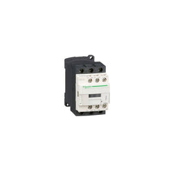
TeSys Deca contactor, 4 poles (4NO), for non-inductive load applications up to 20A/440V AC-1. They can be used to create motor starters for almost any type of application. It provides a 240V 50/60Hz AC coil, 1NO+1NC built-in auxiliary contacts (NC mirror certified), connection by screw clamp terminals. For operating rates until 3600 cycles/hour and environments until 60°C, it procures high reliability and durability. Compact (45mm width), DIN-rail mounting or screw fixing. Power contacts have a 20A resistive load rating. Multi standards certified (IEC, UL, CSA, CCC, EAC, Marine). Contactor has one normally open and one normally closed auxiliary contact built-in as standard. The NC contact is mirror certified. Screw clamp terminals are used for load and auxiliary connections. An extensive line of accessories makes it easy to meet the requirements of most applications. The contactor is 3.35 inches tall, 1.77 inches wide and 3.62 inches deep. It weighs 0.80 lbs. Contactor is certified to UL, CSA, IEC, CCC, EAC and Marine standards.
Main
| Characteristic | Value(s) |
|---|---|
| Range | TeSys TeSys Deca |
| Range of Product | TeSys Deca |
| Product or Component Type | Contactor |
| Device short name | LC1D |
| Contactor application | Resistive load |
| Utilisation category | AC-1 |
| Poles description | 4P |
| [Ue] rated operational voltage | Power circuit <= 690 V AC 25...400 Hz Power circuit <= 300 V DC |
| [Ie] rated operational current | 20 A (at <140 °F (60 °C)) at <= 440 V AC AC-1 for power circuit |
| [Uc] control circuit voltage | 240 V AC 50/60 Hz |
Complementary
| Characteristic | Value(s) |
|---|---|
| Compatibility code | LC1D |
| Pole contact composition | 4 NO |
| Protective cover | With |
| [Ith] conventional free air thermal current | 10 A (at 140 °F (60 °C)) for signalling circuit 20 A (at 140 °F (60 °C)) for power circuit |
| Irms rated making capacity | 140 A AC for signalling circuit conforming to IEC 60947-5-1 250 A DC for signalling circuit conforming to IEC 60947-5-1 250 A at 440 V for power circuit conforming to IEC 60947 |
| Rated breaking capacity | 250 A at 440 V for power circuit conforming to IEC 60947 |
| [Icw] rated short-time withstand current | 30 A 104 °F (40 °C) - 10 min for power circuit 61 A 104 °F (40 °C) - 1 min for power circuit 105 A 104 °F (40 °C) - 10 s for power circuit 210 A 104 °F (40 °C) - 1 s for power circuit 100 A - 1 s for signalling circuit 120 A - 500 ms for signalling circuit 140 A - 100 ms for signalling circuit |
| Associated fuse rating | 10 A gG for signalling circuit conforming to IEC 60947-5-1 25 A gG at <= 690 V coordination type 1 for power circuit 20 A gG at <= 690 V coordination type 2 for power circuit |
| Average impedance | 2.5 mOhm - Ith 20 A 50 Hz for power circuit |
| Power dissipation per pole | 1.56 W AC-1 |
| [Ui] rated insulation voltage | Power circuit 600 V CSA Power circuit 600 V UL Signalling circuit 690 V IEC 60947-1 Signalling circuit 600 V CSA Signalling circuit 600 V UL Power circuit 690 V IEC 60947-4-1 |
| Overvoltage category | III |
| pollution degree | 3 |
| [Uimp] rated impulse withstand voltage | 6 kV IEC 60947 |
| Safety reliability level | B10d = 1369863 cycles contactor with nominal load EN/ISO 13849-1 B10d = 20000000 cycles contactor with mechanical load EN/ISO 13849-1 |
| Mechanical durability | 15 Mcycles |
| Control circuit type | AC 50/60 Hz |
| Coil technology | Without built-in suppressor module |
| Control circuit voltage limits | 0.3...0.6 Uc (-40â¦158 °F (-40â¦70 °C)):drop-out AC 50/60 Hz 0.8...1.1 Uc (-40â¦140 °F (-40â¦60 °C)):operational AC 50 Hz 0.85...1.1 Uc (-40â¦140 °F (-40â¦60 °C)):operational AC 60 Hz 1...1.1 Uc (140â¦158 °F (60â¦70 °C)):operational AC 50/60 Hz |
| Inrush power in VA | 70 VA 60 Hz cos phi 0.75 (at 68 °F (20 °C)) 70 VA 50 Hz cos phi 0.75 (at 68 °F (20 °C)) |
| Hold-in power consumption in VA | 7.5 VA 60 Hz cos phi 0.3 (at 68 °F (20 °C)) 7 VA 50 Hz cos phi 0.3 (at 68 °F (20 °C)) |
| Heat dissipation | 2â¦3 W at 50/60 Hz |
| Operating time | 4...19 ms opening 12...22 ms closing |
| Maximum operating rate | 3600 cyc/h at 60 °C |
| Connections - terminals | Control circuit: screw clamp terminals 2 0.002â¦0.004 in² (1â¦2.5 mm²) - cable stiffness: flexible with cable end Control circuit: screw clamp terminals 1 0.002â¦0.006 in² (1â¦4 mm²) - cable stiffness: flexible without cable end Control circuit: screw clamp terminals 2 0.002â¦0.006 in² (1â¦4 mm²) - cable stiffness: flexible without cable end Control circuit: screw clamp terminals 1 0.002â¦0.006 in² (1â¦4 mm²) - cable stiffness: flexible with cable end Control circuit: screw clamp terminals 1 0.002â¦0.006 in² (1â¦4 mm²) - cable stiffness: solid without cable end Control circuit: screw clamp terminals 2 0.002â¦0.006 in² (1â¦4 mm²) - cable stiffness: solid without cable end Power circuit: screw clamp terminals 1 0.002â¦0.006 in² (1â¦4 mm²) - cable stiffness: flexible without cable end Power circuit: screw clamp terminals 2 0.002â¦0.006 in² (1â¦4 mm²) - cable stiffness: flexible without cable end Power circuit: screw clamp terminals 1 0.002â¦0.006 in² (1â¦4 mm²) - cable stiffness: flexible with cable end Power circuit: screw clamp terminals 2 0.002â¦0.004 in² (1â¦2.5 mm²) - cable stiffness: flexible with cable end Power circuit: screw clamp terminals 1 0.002â¦0.006 in² (1â¦4 mm²) - cable stiffness: solid without cable end Power circuit: screw clamp terminals 2 0.002â¦0.006 in² (1â¦4 mm²) - cable stiffness: solid without cable end |
| Tightening torque | Control circuit 15.05 lbf.in (1.7 N.m) screw clamp terminals flat à 6 mm Control circuit 15.05 lbf.in (1.7 N.m) screw clamp terminals Philips No 2 Power circuit 15.05 lbf.in (1.7 N.m) screw clamp terminals flat à 6 mm Power circuit 15.05 lbf.in (1.7 N.m) screw clamp terminals Philips No 2 Control circuit 15.05 lbf.in (1.7 N.m) screw clamp terminals pozidriv No 2 Power circuit 15.05 lbf.in (1.7 N.m) screw clamp terminals pozidriv No 2 |
| Auxiliary contact composition | 1 NO + 1 NC |
| Auxiliary contacts type | Mechanically linked 1 NO + 1 NC IEC 60947-5-1 Mirror contact 1 NC IEC 60947-4-1 |
| Signalling circuit frequency | 25...400 Hz |
| Minimum switching voltage | 17 V for signalling circuit |
| Minimum switching current | 5 mA for signalling circuit |
| Insulation resistance | > 10 MOhm for signalling circuit |
| Non-overlap time | 1.5 ms on de-energisation between NC and NO contact 1.5 ms on energisation between NC and NO contact |
| Mounting Support | Plate Rail |