
 1 year warranty


motor mechanism, MT 100/160, Compact NSX100/160, PowerPact Multistandard H, 220 to 240 VAC 50/60 Hz, 208 to 277 VAC 60 Hz

Rack M340 - 8 slots - panel, plate or DIN rail mounting
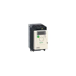
Variable Speed Drive Altivar ATV12 - 0.75kW - 1hp - 200..240V - 3ph - with Heat Sink
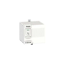
regulated SMPS - 1 or 2-Phase - 100..240 V - 24 V - 20 A
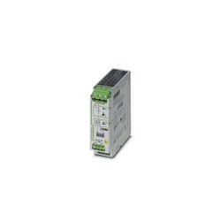
Active QUINT redundancy module for DIN rail mounting with ACB (Auto Current Balancing) Technology and monitoring functions, input: 24 V DC/2x 20 A, output: 24 V DC/1 x 40 A, including mounted UTA 107/30 universal DIN rail adapter

Main
| Characteristic | Value(s) |
|---|---|
| Range of Product | Twido |
| Product or Component Type | Compact base controller |
| Discrete I/O number | 40 |
| Discrete input number | 24 |
| Discrete input voltage | 24 V |
| Discrete input voltage type | DC |
| Discrete output number | 14 relay 2 transistor |
| [Us] rated supply voltage | 100...240 V AC |
| Maximum Number of I/O Expansion Module | 7 |
| Use of slot | Memory cartridge |
| Data backed up | Internal RAM external battery TSXPLP01, 3 years |
| Integrated connection type | Power supply Non isolated serial link mini DIN, Modbus/character mode master/slave RTU/ASCII RS485) half duplex, 38.4 kbit/s Serial link interface adaptor RS232C/RS485) |
| Complementary function | Event processing PID |
| Range Compatibility | Twido |
Complementary
| Characteristic | Value(s) |
|---|---|
| Discrete input logic | Sink or source |
| Input voltage limits | 20.4...26.4 V |
| Discrete input current | 11 mA I0.0 to I0.1 11 mA I0.6 to I0.7 7 mA I0.2 to I0.5 7 mA I0.8 to I0.23 |
| Input impedance | 2100 Ohm I0.0 to I0.1 2100 Ohm I0.6 to I0.7 3400 Ohm I0.2 to I0.5 3400 Ohm I0.8 to I0.23 |
| Filter time | 150 µs + programmed filter time for I0.6 to I0.23 at state 0 35 µs + programmed filter time for I0.0 to I0.5 at state 1 40 µs + programmed filter time for I0.0 to I0.5 at state 0 40 µs + programmed filter time for I0.6 to I0.23 at state 1 |
| Insulation between channel and internal logic | 1500 Vrms for 1 minute |
| Insulation resistance between channel | None |
| Minimum load | 0.1 mA |
| Contact resistance | 30000 µOhm |
| Load current | 2 A 240 V AC inductive 30 cyc/mn relay output 2 A 240 V AC resistive 30 cyc/mn relay output 2 A 30 V DC inductive 30 cyc/mn relay output 2 A 30 V DC resistive 30 cyc/mn relay output |
| Mechanical durability | 20000000 cycles relay output |
| Electrical durability | 100000 cycles relay output |
| Current consumption | 128 mA 24 V DC at state 1 128 mA 24 V DC state 1 + input ON 140 mA 5 V DC state 1 + input ON 5 mA 24 V DC at state 0 70 mA 5 V DC at state 0 90 mA 5 V DC at state 1 |
| I/O connection | Non-removable screw terminal block |
| Maximum input/output number | 152 removable screw terminal block with I/O expansion module 208 spring terminal block with I/O expansion module 264 HE-10 connector with I/O expansion module |
| Network Frequency | 50/60 Hz |
| Supply voltage limits | 85â¦264 V |
| Network frequency limits | 47â¦63 Hz |
| Power supply output current | 0.4 A 24 V DC sensors |
| Input current | 790 mA |
| Inrush current | 35 A |
| Protection type | Power protection internal fuse |
| Power consumption in VA | 65 VA 100 V 77 VA 264 V |
| Insulation resistance | > 10 MOhm at 500 V, between I/O and earth terminals > 10 MOhm at 500 V, between supply and earth terminals |
| Program memory | 3000 instructions |
| Exact time for 1 Kinstruction | 1 ms |
| System overhead | 0.5 ms |
| Memory description | Internal RAM, 128 counters, no floating, no trigonometrical Internal RAM, 128 timers, no floating, no trigonometrical Internal RAM, 256 internal bits, no floating, no trigonometrical Internal RAM, 3000 internal words, no floating, no trigonometrical Internal RAM, double words, no floating, no trigonometrical Internal RAM, floating, trigonometrical |
| Free slots | 1 |
| Realtime clock | With <= 30 s/month 30 days |
| Positioning functions | PWM/PLS 2 7 kHz |
| Counting input number | 2 20000 Hz 32 bits 4 5000 Hz 16 bits |
| Analogue adjustment points | 1 point adjustable from 0 to 511 points 1 point adjustable from 0...1023 |
| Status LED | 1 LED (Green) PWR 1 LED (Green) RUN 1 LED per channel (Green) I/O status 1 LED (Red) module error (ERR) 1 LED user pilot light (STAT) |
| Depth | 2.8 in (70 mm) |
| Height | 3.7 in (95 mm) |
| Width | 3.5 in (90 mm) |
| Product Weight | 1.157 lb(US) (0.525 kg) |

Main
| Characteristic | Value(s) |
|---|---|
| Range of Product | Modicon M238 logic controller |
| Product or Component Type | Input/output analog module |
| Analogue input number | 2 |
| Input level | Low level |
| Analogue input type | 3-wire Pt probe temperature probe - 100...500 °C differential thermocouple 0...1200 °C thermocouple J differential thermocouple 0...1300 °C thermocouple K differential thermocouple 0...400 °C thermocouple T differential |
| Analogue output number | 1 |
| Analogue output type | Current 4...20 mA Voltage 0...10 V |
| Cross talk | <= 2 LSB |
Complementary
| Characteristic | Value(s) |
|---|---|
| Range Compatibility | Advantys OTB Twido |
| Analogue input resolution | 12 bits |
| Analogue output resolution | 12 bits |
| LSB value | 2.5 mV voltage voltage 4.8 µA current current 0.1 °C thermocouple 0.15 °C temperature probe |
| Input impedance | >= 1 MOhm |
| Load type | Resistive |
| Load impedance ohmic | >= 2000 Ohm voltage <= 300 Ohm current |
| Stabilisation time | 20 ms |
| Conversion time | 20 ms + 1 controller cycle time |
| Sampling duration | 20 ms temperature probe 60 ms thermocouple |
| Acquisition period | 60 ms per channel + 1 controller cycle time thermocouple 80 ms per channel + 1 controller cycle time |
| Measurement error | +/- 0.2 % of full scale - 100...500 °C 3-wire Pt probe 25 °C +/- 0.2 % of full scale 0...10 V 0...10 V 25 °C +/- 0.2 % of full scale 4...20 mA 4...20 mA 25 °C 0.2 % of full scale +/- 4 °C 0...1200 °C thermocouple J 25 °C 0.2 % of full scale +/- 4 °C 0...1300 °C thermocouple K 25 °C 0.2 % of full scale +/- 4 °C 0...400 °C thermocouple T 25 °C |
| Temperature coefficient | +/-0.006 %FS/°C - 100...500 °C 3-wire Pt probe +/-0.006 %FS/°C 0...1200 °C thermocouple J +/-0.006 %FS/°C 0...1300 °C thermocouple K +/-0.006 %FS/°C 0...400 °C thermocouple T +/-0.015 %FS/°C 0...10 V 0...10 V +/-0.015 %FS/°C 4...20 mA 4...20 mA |
| Repeat accuracy | +/-0.5 %FS input/output |
| Non-linearity | +/- 0.2 %FS current current +/- 0.2 %FS temperature probe +/- 0.2 %FS thermocouple +/- 0.2 %FS voltage voltage |
| Output error | +/- 1 %FS |
| Output ripple | <= 1 LSB |
| Total error | +/-1 %FS current current +/-1 %FS temperature probe +/-1 %FS thermocouple +/-1 %FS voltage voltage |
| Type of Cable | Shielded cable |
| Insulation between channel and internal logic | Photocoupler |
| Supply | External supply |
| [Us] rated supply voltage | 24 V DC |
| Supply voltage limits | 19.2â¦30 V |
| Electrical connection | 1 removable screw terminal block |
| Current consumption | 50 mA 24 V DC external 50 mA 5 V DC internal |
| Product Weight | 0.187 lb(US) (0.085 kg) |

TeSys F - main contact set - 3P

Fiber Converter MM/LC 2CH 100Mb
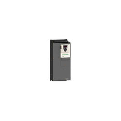
Variable Speed Drive Altivar 71 - 30kW-40hp - 480V - with EMC filter whitout Graphic Terminal

controller M241 40 IO transistor NPN Ethernet
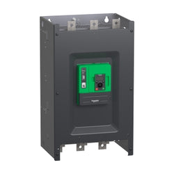
Altivar Soft Starter ATS480 is intended to start and stop asynchronous motors supplied from 208V to 690V. It meets the requirements of the most demanding applications in normal and heavy duty. With an operational rated current of 590A in normal duty, it supplies motor from 160kW to 560kW according to mains voltage. Designed for digitization, connected, optimized to meet cybersecurity standard, it simplifies project execution and maximizes the availability of applications. Its torque control (TCS) masters acceleration and deceleration. It efficiently stops high inertia application thanks to the dynamic braking and DC injection. It could be connected in-line or inside the delta to reduce its operational current. The embedded test routine simplifies the commissioning inside the delta. Its dimensions are 400mm (width) x 314mm (depth) x 670mm (height) and it weighs 51,4kg. Altivar Soft Starter ATS480 is designed to address process, infrastructures and industrial machines. It conforms to IEC/EN60947-4-1. It is certified CE, cULus, UKCA, CCC, RCM, EAC, and Marine certified DNV, ABS, BV and CCS. Display terminals, remote mounting kit, communication modules are common with Altivar Drives. Line chokes, DNV kits are common with ATS48. ATS480 is compatible with ATS48, it has same footprint, fixing, torque control algorithm, I/O, menus⦠The integration of Altivar Soft Starter ATS480 in EcoStruxure drastically simplifies architecture selection, detailed design and execution in automation and electrical systems.
Main
| Characteristic | Value(s) |
|---|---|
| Range of Product | Altivar Soft Starter ATS480 |
| Product or Component Type | Soft starter |
| Product destination | Asynchronous motors |
| Product Specific Application | Process and infrastructures |
| Device short name | ATS480 |
| Phase | 3 phase |
| Utilisation category | AC-3A AC-53A |
| Ue power supply voltage | 208...690 V - 15...10 % |
| power supply frequency | 50...60 Hz - 20...20 % |
| [Ie] rated operational current | Normal duty 590.0 A 104 °F (40 °C)) |
| rated current in heavy duty | 480.0 A at 104 °F (40 °C) heavy duty |
| Torque control | True |
| IP Degree of Protection | IP00 |
| Motor power kW | 160.0 kW 230 V in the motor supply line normal duty 132.0 kW 230 V in the motor supply line heavy duty 315.0 kW 400 V in the motor supply line normal duty 250.0 kW 400 V in the motor supply line heavy duty 355.0 kW 440 V in the motor supply line normal duty 250.0 kW 440 V in the motor supply line heavy duty 400.0 kW 500 V in the motor supply line normal duty 315.0 kW 500 V in the motor supply line heavy duty 400.0 kW 525 V in the motor supply line normal duty 315.0 kW 525 V in the motor supply line heavy duty 560.0 kW 660 V in the motor supply line normal duty 400.0 kW 660 V in the motor supply line heavy duty 560.0 kW 690 V in the motor supply line normal duty 500.0 kW 690 V in the motor supply line heavy duty 250.0 kW 230 V to the motor delta terminals heavy duty 400.0 kW 400 V to the motor delta terminals normal duty 355.0 kW 400 V to the motor delta terminals heavy duty |
| Maximum Horse Power Rating | 150.0 hp 208 V heavy duty 200.0 hp 230 V normal duty 400.0 hp 460 V normal duty 350.0 hp 460 V heavy duty 500.0 hp 575 V normal duty 400.0 hp 575 V heavy duty |
| Option card | Communication module Profibus DP V1 Communication module Modbus TCP/EtherNet/IP Communication module CANopen daisy chain Communication module CANopen Sub-D Communication module CANopen open style Communication module PROFINET |
Complementary
| Characteristic | Value(s) |
|---|---|
| Device connection | In the motor supply line To the motor delta terminals |
| [Us] control circuit voltage | 110...230 V AC 50/60 Hz - 15...10 % |
| Apparent power | 0.125 kVA |
| Integrated motor overload protection | True |
| motor thermal protection class | Class 10E |
| Protection type | Phase failure line Integrated thermal protection motor Thermal protection starter Current overload motor Underload motor Excessive starting time, locked rotor motor Motor phase loss motor Line supply phase loss line Line supply phase loss motor Thermal protection motor |
| current limiting %In (5 x Ie maximum) | 150â¦700 % |
| [In] Rated current pwr loss specifctn | 590.0 A |
| Power loss static current independent | 25.0 W |
| Power loss per device current dependent | 1711.0 W |
| Standards | IEC 60947-4-2 UL 60947-4-2 IEC 60664-1 |
| Product Certifications | CE cULus CCC UKCA RCM EAC DNV ABS BV CCS |
| Marking | CE CCC UKCA EAC RCM CULus |
| [Uc] control circuit voltage | 24 V DC |
| Discrete input number | 4 |
| Discrete input type | STOP) logic inputs, 3500 Ohm RUN) logic inputs, 3500 Ohm DI3) programmable as logic input, 3500 Ohm DI4) programmable as logic input, 3500 Ohm |
| Input compatibility | STOP discrete input level 1 PLC IEC 61131-2 RUN discrete input level 1 PLC IEC 61131-2 DI3 discrete input level 1 PLC IEC 61131-2 DI4 discrete input level 1 PLC IEC 61131-2 |
| Discrete input logic | Programmable digital input < 5 V |
| Relay output number | 3 |
| Relay output type | Relay outputs R1A 1 NO Relay outputs R1B 1 NO Relay outputs RIC NO/NC programmable |
| Minimum switching current | 100 mA 12 V DC relay outputs |
| Maximum switching current | Relay outputs 2 A 250 V AC Relay outputs 2 A 30 V DC Relay outputs |
| Discrete output number | 2 |
| Discrete output type | DQ1) programmable digital output <= 30 V DQ2) programmable digital output <= 30 V |
| Output compatibility | Open collector level 1 PLC IEC 65A-68 |
| Analogue input number | 1 |
| Analogue input type | AI1/PTC PTC/Pt 100 temperature probe PTC2 PTC/Pt 100 temperature probe PTC3 PTC/Pt 100 temperature probe |
| Analogue output number | 1 |
| Analogue output type | Current output AQ1 0...20 mA or 0...10 V 500 Ohm |
| Communication Port Protocol | Modbus serial |
| Connector Type | 1 RJ45 |
| Communication data link | Serial |
| Physical interface | 2-wire RS 485 |
| Transmission Rate | 1200...256000 bit/s |
| Transmission frame | RTU |
| Data format | 8 bits, configurable odd, even or no parity |
| Type of polarization | No impedance Modbus serial |
| Number of addresses | 0â¦227 Modbus serial |
| Method of access | Slave Modbus serial |
| Function Available | External bypass control Pre-heating Smoke extraction Multi-motor cascade Second motor set User management Ports and services hardening Security event logging Cybersecure firmware update Single direction |
| Display screen available | True |
| Operating position | Vertical +/- 10 degree |
| Height | 26.4 in (670.0 mm) |
| Width | 15.7 in (400.0 mm) |
| Depth | 12.4 in (314.0 mm) |
| Product Weight | 113.3 lb(US) (51.4 kg) |

This product is part of the Lexium 28 range, an offer of motion servo drives for machines from 0.05 to 4.5kW. The motion servo drive without EMC filter, features a HMI interface 7-segment display with 5 buttons. Thanks to its open communication concept, Lexium 28 servo drive can be easily integrated into numerous different control system architectures. It is a motion servo drive with a rated supply voltage of 220V (single and three phase), an output current of 7.8A at 220V, a power of 400W/0.53HP and a continuous power of 400W at 220V. It is furnished with spring terminal for electrical connection and RJ45 connectors for CANopen, CANmotion integrated communication interfaces. Physical interface is RS485 for Modbus Serial line slave. It is an IP20 rated product. Its dimensions are 55mm (Width) x 146mm (Depth) x 150mm (Height). It weighs 1kg. This product is certified by CE, CSA and CULus. It meets EN/IEC 61800-5-1 standards. This product is compatible with servo motor BCH2 (60mm, 2 motor stacks) at 400W, servo motor BCH2 (80mm, 1 motor stacks) at 400W and servo motor BCH2 (130mm, 1 motor stacks) at 300W. Lexium 28 and Lexium BCH2, the optimized servo bundle for all motion control solutions are cost effective, energy efficient and embedded safety. Lexium 28 servo drives and Lexium BCH2 servo motors, optimized servo bundles for compact machines.
Main
| Characteristic | Value(s) |
|---|---|
| Range of Product | Lexium 28 |
| Device short name | LXM28A |
| Product or Component Type | Motion servo drive |
| Format of the drive | Compact housing |
| Line current | 3.8 A 211.6 % 220 V, single phase 3.8 A 183.7 % 220 V, three phase |
Complementary
| Characteristic | Value(s) |
|---|---|
| Phase | Three phase Single phase |
| [Us] rated supply voltage | 200...240 V - 10...15 %)three phase 200...240 V - 20...15 %)single phase |
| Supply voltage limits | 200â¦255 V three phase 170â¦255 V single phase |
| Supply frequency | 50/60 Hz - 5...5 % |
| Network Frequency | 47.5...63 Hz |
| EMC filter | Without EMC filter |
| Continuous output current | 2.6 A 16 kHz |
| Output current 3s peak | 7.8 A 220 V |
| Continuous power | 400 W 220 V |
| Nominal power | 0.4 kW 220 V 16 kHz |
| Switching frequency | 16 kHz |
| Overvoltage category | III |
| Maximum leakage current | 1.3 mA |
| Output voltage | <= power supply voltage |
| Electrical isolation | Between power and control |
| Type of cable | Shielded motor cable 32â¦131 °F (0â¦55 °C)) copper |
| Electrical connection | Spring terminal 0.82...1 mm², AWG 18 L1-L2) Spring terminal 0.82...1 mm², AWG 18 R, S, T) Spring terminal 0.82...1 mm², AWG 18 U, V, W, PE) Spring terminal 0.82...1 mm², AWG 18 PA/+, PBe) |
| Discrete input number | 8 programmable CN1) 1 pulse train input (PTI) CN1) 2 fast capture CN1) 1 safety function STO CN9) |
| Discrete input voltage | 24 V DC logic |
| Discrete input logic | Positive or negative CN1) |
| Discrete output number | 5 logic output CN1)12...24 V DC 1 pulse train output (PTO) CN1) |
| Discrete output voltage | 12...24 V DC |
| Discrete output logic | Positive or negative CN1) |
| Analogue input number | 2 |
| Absolute accuracy error | 0.1 % |
| Analogue input type | V_REF voltage analog input - 10...10 V 10 kOhm 14 bits T_REF voltage analog input |
| Control signal type | Servo motor encoder feedback CN2 |
| Protection type | Against reverse polarity inputs signal Against short-circuits outputs signal Overcurrent motor Overvoltage motor Undervoltage motor Overheating motor Overload motor Overspeed motor |
| Safety function | STO (safe torque off), Integrated |
| Safety level | SIL 2 IEC 61800-5-2 2007 SIL 2 IEC 61508-1 2010 PL d/category 3 ISO 13849-1 2008 SIL 2 ISO 13849-1 2009/AC SIL 2 IEC 60204-1 2006 SIL 2 IEC 60204-1 2009/A1 SIL 2 IEC 60204-1 2010/AC SIL 2 IEC 62061 2012 |
| Communication interface | CANopen, Integrated CANmotion, Integrated |
| Connector type | RJ45 CN4)CANopen, CANmotion |
| Method of access | Slave |
| Transmission rate | 250 kbit/s 328.08â¦820.2 ft (100â¦250 m) CANopen, CANmotion 500 kbit/s 13.1â¦328.08 ft (4â¦100 m) CANopen, CANmotion 1 Mbit/s 13.1 ft (4 m) CANopen, CANmotion |
| Number of addresses | 1â¦127 CANopen, CANmotion |
| Physical interface | RS485 Modbus Serial line slave |
| Status LED | 1 LED (Red) charge 1 LED (Green) RUN 1 LED (Red) error |
| Signalling function | Servo status and fault codes five 7-segment display units |
| Marking | CSA CE CULus |
| type of cooling | Natural convection |
| Operating position | Vertical |
| Product compatibility | Servo motor BCH2 2.4 in (60 mm), 2 400 W Servo motor BCH2 3.1 in (80 mm), 1 400 W Servo motor BCH2 5.1 in (130 mm), 1 300 W |
| Width | 2.2 in (55 mm) |
| Height | 5.9 in (150 mm) |
| Depth | 5.7 in (146 mm) |
| Product Weight | 2.2 lb(US) (1 kg) |
| Supply voltage description | Three phase 220 V AC 50...60 Hz Single phase 220 V AC 50...60 Hz |
| Network number of phases | 1 3 |
| Drive voltage drop coefficient | 1 |
| Field weakening | False |
| Continuous output current 2 | 2.6 A |
| Output current 3s peak 2 | 7.8 A 220 V |
| Switching frequency 2 | 16 kHz |
| Continuous output current 3 | 2.6 A |
| Output current 3s peak 3 | 7.8 A 220 V |
| Switching frequency 3 | 16 kHz |
| communication interface | Pulse train input CANmotion Pulse train output CANopen DS402 |
| Emc filter compatibility | Type 022 Type 020 |

Configurable safe small controllers PNOZmulti 2 base unit, expandable, Ethernet interface with switch, USB 20 memory.

ACS510-01-157A-4,157A,380V,IP21; ACS510-01-157A-4,157A,380V,IP21
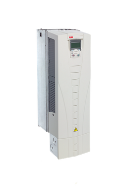
ACS510,72A,380V; ACS510-01-072A-4
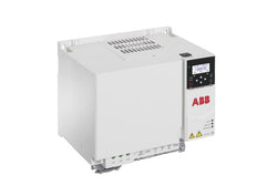
ACS380-040S-032A-4 PN: 15kW, IN: 32A; The ACS380 machinery drive comes in several variants, ensuring seamless integration into machines and connecting perfectly to automation systems. It’s a great fit for industries such as food and beverage, material handling and textile. Typical applications include mixers, conveyors, EOT and tower cranes, extruders, and textile machinery. With the integrated functional safety features, the ACS380 drive can be also part of the machine’s safety system via PROFIsafe over PROFINET, ensuring the motor is safely stopped when required. In addition, the drive’s software can be easily customized with adaptive programming to match any specific application requirements.

ACS380-040S-06A9-1 PN: 1.1kW, IN: 6.9A; The ACS380 machinery drive comes in several variants, ensuring seamless integration into machines and connecting perfectly to automation systems. It’s a great fit for industries such as food and beverage, material handling and textile. Typical applications include mixers, conveyors, EOT and tower cranes, extruders, and textile machinery. With the integrated functional safety features, the ACS380 drive can be also part of the machine’s safety system via PROFIsafe over PROFINET, ensuring the motor is safely stopped when required. In addition, the drive’s software can be easily customized with adaptive programming to match any specific application requirements.
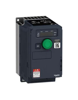
This Altivar 320 variable speed drive can feed three-phase synchronous and asynchronous motors. Its compact form factor allows vertical stacking of drives inside machine frames. It works at a rated power up to 0.18kW / 0.25hp and a rated voltage from 200V to 240V AC. Its robust design with IEC 60721-3-3 class 3C3 coated printed circuit boards allows to extend machine availability in harsh environmental conditions, for example at ambient temperatures of up to 60°C without the need of additional cooling. It incorporates functions suitable for the most common applications, including torque and speed accuracy at very low speed, high dynamic performance with flux vector control without sensor and extended frequency range for high-speed motors. It also incorporates parallel connection of motors and special drives using the voltage/frequency ratio and static speed accuracy and energy saving for open-loop synchronous motors. The drive software includes 5 safety functions that help machines meet safety requirements, whether or not they are used in conjunction with a Preventa safety module. These safety functions are configured using SoMove software. Altivar Machine ATV320 was designed for Original Equipment Manufacturers (OEMs) that meets simple and advanced application requirements covered for packaging, material handling, textile, material working, mechanical actuators and hoisting. It conforms to international standards IEC/EN 61800-5-1 and IEC/EN 61800-3 (immunity and conducted and radiated EMC emissions). It is also CE, UL, CSA, NOM, EAC and RCM certified. Mounting accessories and external options (braking resistors, line chokes, motor chokes, additional EMC filters) are available with Altivar Machine ATV320 drives. The type of external accessories and options depends on the drive rating. It is designed to be mounted in vertical position (+/- 10 °) on a panel, thanks to 4 fixing holes. It is fully integrated inside Schneider Electricâs EcoStruxure Machine through DTM. It is possible to configure, control, and diagnose ATV320 drives directly in SoMachine and SoMove software by means of the same software brick (DTM).
Main
| Characteristic | Value(s) |
|---|---|
| Range of Product | Altivar Machine ATV320 |
| Product or Component Type | Variable speed drive |
| Product Specific Application | Complex machines |
| Variant | Standard version |
| Format of the drive | Compact |
| Mounting Mode | Wall mount |
| Communication Port Protocol | Modbus serial CANopen |
| Option card | communication module, CANopen communication module, EtherCAT communication module, Profibus DP V1 communication module, PROFINET communication module, Ethernet Powerlink communication module, EtherNet/IP communication module, DeviceNet |
| [Us] rated supply voltage | 200...240 V - 15...10 % |
| nominal output current | 1.5 A |
| Motor power kW | 0.18 kW heavy duty |
| EMC filter | Class C2 EMC filter integrated |
| IP degree of protection | IP20 |
Complementary
| Characteristic | Value(s) |
|---|---|
| Discrete input number | 7 |
| Discrete input type | STO safe torque off, 24 V DC1.5 kOhm DI1...DI6 logic inputs, 24 V DC 30 V) DI5 programmable as pulse input 0â¦30 kHz, 24 V DC 30 V) |
| Discrete input logic | Positive logic (source) Negative logic (sink) |
| Discrete output number | 3 |
| Discrete output type | Open collector DQ+ 0â¦1 kHz 30 V DC 100 mA Open collector DQ- 0â¦1 kHz 30 V DC 100 mA |
| Analogue input number | 3 |
| Analogue input type | AI1 voltage 0...10 V DC 30 kOhm 10 bits AI2 bipolar differential voltage +/- 10 V DC 30 kOhm 10 bits AI3 current 0...20 mA (or 4-20 mA, x-20 mA, 20-x mA or other patterns by configuration) 250 Ohm 10 bits |
| Analogue output number | 1 |
| Analogue output type | Software-configurable current AQ1 0...20 mA 800 Ohm 10 bits Software-configurable voltage AQ1 0...10 V DC 470 Ohm 10 bits |
| Relay output type | Configurable relay logic R1A 1 NO 100000 cycles Configurable relay logic R1B 1 NC 100000 cycles Configurable relay logic R1C Configurable relay logic R2A 1 NO 100000 cycles Configurable relay logic R2C |
| Maximum switching current | Relay output R1A, R1B, R1C resistive, cos phi = 1 3 A 250 V AC Relay output R1A, R1B, R1C resistive, cos phi = 1 3 A 30 V DC Relay output R1A, R1B, R1C, R2A, R2C inductive, cos phi = 0.4 7 ms 2 A 250 V AC Relay output R1A, R1B, R1C, R2A, R2C inductive, cos phi = 0.4 7 ms 2 A 30 V DC Relay output R2A, R2C resistive, cos phi = 1 5 A 250 V AC Relay output R2A, R2C resistive, cos phi = 1 5 A 30 V DC |
| Minimum switching current | Relay output R1A, R1B, R1C, R2A, R2C 5 mA 24 V DC |
| Method of access | Slave CANopen |
| 4 quadrant operation possible | True |
| Asynchronous motor control profile | Voltage/frequency ratio, 5 points Flux vector control without sensor, standard Voltage/frequency ratio - Energy Saving, quadratic U/f Flux vector control without sensor - Energy Saving Voltage/frequency ratio, 2 points |
| Synchronous motor control profile | Vector control without sensor |
| Maximum output frequency | 0.599 kHz |
| Acceleration and deceleration ramps | Linear U S CUS Ramp switching Acceleration/deceleration ramp adaptation Acceleration/deceleration automatic stop with DC injection |
| Motor slip compensation | Automatic whatever the load Adjustable 0...300 % Not available in voltage/frequency ratio (2 or 5 points) |
| Switching frequency | 2...16 kHz adjustable 4...16 kHz with derating factor |
| Nominal switching frequency | 4 kHz |
| Braking to standstill | By DC injection |
| Brake chopper integrated | True |
| Line current | 3.4 A 200 V heavy duty) 2.8 A 240 V heavy duty) |
| Maximum Input Current per Phase | 3.4 A |
| Maximum output voltage | 240 V |
| Apparent power | 0.7 kVA 240 V heavy duty) |
| Network Frequency | 50-60 Hz |
| Relative symmetric network frequency tolerance | 5 % |
| Prospective line Isc | 1 kA |
| Base load current at high overload | 6.9 A |
| Power dissipation in W | Self-cooled 17.0 W 200 V 4 kHz |
| With safety function Safely Limited Speed (SLS) | True |
| With safety function Safe brake management (SBC/SBT) | False |
| With safety function Safe Operating Stop (SOS) | False |
| With safety function Safe Position (SP) | False |
| With safety function Safe programmable logic | False |
| With safety function Safe Speed Monitor (SSM) | False |
| With safety function Safe Stop 1 (SS1) | True |
| With sft fct Safe Stop 2 (SS2) | False |
| With safety function Safe torque off (STO) | True |
| With safety function Safely Limited Position (SLP) | False |
| With safety function Safe Direction (SDI) | False |
| Protection type | Input phase breaks drive Overcurrent between output phases and earth drive Overheating protection drive Short-circuit between motor phases drive Thermal protection drive |
| Width | 2.8 in (72.0 mm) |
| Height | 5.6 in (143.0 mm) |
| Depth | 4.3 in (109.0 mm) |
| Product Weight | 1.8 lb(US) (0.8 kg) |
| Transient overtorque | 170â¦200 % of nominal motor torque |
Bus Terminal, 2-channel analog input, current, 4…20 mA, 16 bit, differential, high-precision

EtherCAT Terminal, 4-channel analog input, temperature, RTD (Pt100), 16 bit

EtherCAT Terminal, 4-channel analog input, temperature, thermocouple, 16 bit

EtherCAT Terminal, 8-channel analog output, voltage, 0…10 V, 12 bit
Digital Compact Servo Drive, 2-axis module, 100…480 V AC, rated output current 2 x 6 A, EtherCAT interface, OCT, hardware version 2.0, firmware version ? 2.10 (1)