
 1 year warranty


| Product | |
| Article Number (Market Facing Number) | 3TK28231CB30 | 3TK28231CB30 |
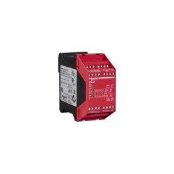
| Product Description | SIRIUS safety relay with relay enabling circuits (EC) 24 V AC/DC, 22.5 mm Screw terminal EC instantaneous: 2 NO EC delayed: 0 NO SC: 0 NC monitored start Basic device Maximum achieved SIL: 3, PL: e |
| Product family | Not available |
| Product Lifecycle (PLM) | PM490:Start of final year of support |
| Additional Product Information | |
| EAN | 4011209380660 |
| UPC | 754554482910 |
| Commodity Code | 85364900 |
| LKZ_FDB/ CatalogID | CC-IC10 |
| Product Group | 5837 |
| Group Code | R711 |
| Country of origin | Germany |
| SCIP number | Not available |
| Delivery information | |
| Net Weight (lb) | 0.538 lb |
| Package size unit of measure | Inch |
| Packaging Quantity | 1 |

| Product | |
| Article Number (Market Facing Number) | 3SE53120SD11 | 3SE53120SD11 |
| Product Description | Safety position switch with tumbler Locking force 2600 N 5 directions of approaches Spring-locked Auxiliary release on front Magnet voltage 24 V DC Monitoring actuator 2 NC/1 NO Monitoring magnet 2 NC/1 NO Supplied without actuator. Actuator 3SE5000-0AV0. please order separately |
| Product family | 3SE5, metal enclosures with locking force greater than 2 000 N |
| Product Lifecycle (PLM) | PM300:Active Product |
| Additional Product Information | |
| EAN | 4011209682955 |
| UPC | Not available |
| Commodity Code | 85365019 |
| LKZ_FDB/ CatalogID | CC-IC10 |
| Product Group | 5317 |
| Group Code | R711 |
| Country of origin | Germany |
| SCIP number | Not available |
| Delivery information | |
| Net Weight (lb) | 2.094 lb |
| Package size unit of measure | in |
| Packaging Quantity | 1 |
Main
| Characteristic | Value(s) |
|---|---|
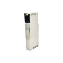
| Range of Product | Modicon Quantum automation platform |
| Product or Component Type | Power supply module |
| Power supply type | Redundant |
Complementary
| Characteristic | Value(s) |
|---|---|
| Input voltage | 115 V 93...138 V) AC 47â¦63 Hz 230 V 170...276 V) AC |
| Input current | 1100 mA 115 V 600 mA 230 V |
| Inrush current | 19 A 230 V 38 A 115 V |
| Rated power in VA | 130 VA |
| Associated fuse rating | 2 A, slow-blow |
| Harmonic distortion | <= 10 % of fundamental rms value |
| Output voltage | 5.1 V DC |
| Power supply output current | 8 A 140 °F (60 °C) redundant |
| Output overvoltage protection | Internal |
| Output overload protection | Internal |
| Power dissipation | 6 + (1.5 x Iout) where Iout is in A |
| Local signalling | 1 LED (green) for power (PWR OK) |
| Marking | CE |
| Module format | Standard |
| Product Weight | 1.43 lb(US) (0.65 kg) |

Main
| Characteristic | Value(s) |
|---|---|
| Range of Product | Modicon Quantum automation platform |
| Product or Component Type | Analogue input module |
| Type of filter | Single pole low pass - 3 dB at 15 Hz +/- 20 % |
Complementary
| Characteristic | Value(s) |
|---|---|
| Analogue input number | 8 |
| Input type | Differential |
| Addressing requirement | 9 input words |
| Analogue input resolution | 12 bits |
| Linear measuring range | 1...5 V 4...20 mA |
| Absolute maximum input | 50 V DC 25 mA |
| Input impedance | 250 Ohm current +/- 0.01 % > 20 MOhm voltage |
| Absolute accuracy error | +/- 0.05 % of full scale +/- 0.1 % of full scale maximum |
| Linearity error | +/- 0.04 % |
| Accuracy drift according to temperature | +/- 0.0025 % of full scale/°C <= 0.005 % of full scale/°C |
| Common mode rejection | > - 72 dB 60 Hz |
| Isolation between channels and bus | 1000 V DC 3000 V DC 60 s |
| Isolation between channels | 30 V DC |
| Update time | 5 ms |
| Fault type | Broken wire 4...20 mA Undervoltage range 1...5 V |
| Marking | CE |
| Local signalling | 1 LED (green) for bus communication is present (Active) 1 LED (red) for external fault 8 LEDs (green) for channel is turned on 8 LEDs (red) for channel fault |
| Bus current requirement | 240 mA |
| Power dissipation in W | 2 W |
| Module format | Standard |
| Product Weight | 0.7 lb(US) (0.3 kg) |
module XPSAK - Emergency stop - 120 V AC

Main
| Characteristic | Value(s) |
|---|---|
| Range of Product | Harmony XBTGT |
| Product or Component Type | Advanced touchscreen panel |
| Display Type | Backlit colour TFT LCD |
| Display colour | 65536 colours |
| Display Resolution | 800 x 600 pixels SVGA |
| Display size | 12.1 inch |
| Software Type | Configuration software |
| Software Designation | Vijeo Designer |
| Operating System | Harmony |
| Processor name | CPU RISC |
| Processor frequency | 266 MHz |
| Memory description | 512 KB SRAM back up of data lithium battery 32 MB flash EPROM application memory |
| Integrated connection type | RJ45 COM2 serial link RS485 <= 187.5 kbit/s Siemens MPI (187.5 kbits/s) male SUB-D 9 COM1 serial link RS232C/RS422/RS485 <= 115.2 kbits/s removable screw terminal block power supply RJ45 Ethernet TCP/IP 3 removable screw terminal block digital output removable screw terminal block audio output removable screw terminal block digital input 2 USB type A master port (V1.1) |
| Resistance to electrostatic discharge | 6 kV IEC 61000-4-2 level 3 |
| Cut-out dimensions | 301.5 (+ 1/- 0) x 227.5 (+ 1/- 0) mm |
Complementary
| Characteristic | Value(s) |
|---|---|
| Touch sensitive zone | 1024 x 1024 |
| Touch panel | Analogue |
| Backlight lifespan | 50000 hours |
| Brightness | 8 levels via touch panel |
| Character font | Chinese (simplified Chinese) Korean ASCII (European characters) Japanese (ANK, Kanji) Taiwanese (traditional Chinese) |
| [Us] rated supply voltage | 24 V DC |
| Supply | External source |
| Supply voltage limits | 19.2â¦28.8 V |
| Inrush current | 30 A |
| Power Consumption in W | 30 W |
| Local signalling | 1 LED (green or orange) for normal operation or backlighting faulty |
| Number of pages | Limited by internal memory capacity |
| Downloadable protocols | Telemecanique Modicon FIPWAY Telemecanique Modicon Modbus Plus Telemecanique Modicon Modbus TCP Telemecanique Modicon Modbus Mitsubishi Melsec third party protocols Omron Sysmac third party protocols Rockwell Automation Allen-Bradley third party protocols Siemens Simatic third party protocols Telemecanique Modicon Uni-TE |
| Realtime clock | Built-in |
| Data storage equipment | 1 Compact Flash card >= 1 GB |
| Use of slot | For 1 fieldbus communication card (Device Net, Profibus DP) |
| Port Ethernet | 10BASE-T/100BASE-TX |
| Product mounting | Flush mounting |
| Fixing Mode | By 4 spring clips By 4 screw clamps |
| Front material | Aluminium alloy |
| Enclosure Material | PPT |
| Marking | CE |
| Width | 12.3 in (313 mm) |
| Height | 9.4 in (239 mm) |
| Depth | 2.2 in (56 mm) |
| Product Weight | 6.6 lb(US) (3 kg) |

Main
| Characteristic | Value(s) |
|---|---|
| Range of Product | ConneXium |
| Product or Component Type | Ethernet Modbus gateway/router |
| Product destination | All products compatible with Modbus standard |
| Concept | Transparent Ready |
| Web server | Class B10 |
| [Us] rated supply voltage | 24 V DC |
Complementary
| Characteristic | Value(s) |
|---|---|
| Web services | Via predefined web pages : diagnostic on Ethernet and Modbus links Predefined web pages Access to connected products list, reading of Modbus devices registers |
| Communication Service | SNMP agent, device administration with a SNMP manager Read/write Modbus registers of connected devices Miniature firewall on-board (IP address filtering) and password protection BOOTP protocol, FDR client |
| Supply | Power supply device PoE IEEE 802.3af |
| Integrated connection type | Ethernet TCP/IP RJ45 10/100 Mbps 1 twisted pair Serial link 5-way removable terminal block Modbus RTU and ASCII RS485 57.6 kbps Serial link micro switches Modbus RTU and ASCII RS485 57.6 kbps Serial link RJ45 RS232 38.4 kbps |
| Maximum Number of Connected Devices | Modbus serial link <32 |
| Port Ethernet | 10BASE-T/100BASE-TX |
| Mounting Support | Symmetrical DIN rail |
| Marking | CE |
| Local signalling | for serial link communication (RS485, RX, TX) 3 LEDs for Ethernet communication (LK, RX, TX, 100) 4 LEDs |
| Width | 2.8 in (72 mm) |
| Height | 3.2 in (81 mm) |
| Depth | 3.0 in (76 mm) |

This Altivar Process ATV900 variable speed drive can feed 3-phase synchronous and asynchronous power motors. It is suitable for motors with power rating up to 5.5kW/7.5hp for applications requiring slight overload (up to 120%). It is suitable for motors with power rating up to 4kW/5hp for applications requiring significant overload (up to 150%). It works at a rated supply voltage from 380V to 480V AC. This variable speed / frequency drive (VSD / VFD) is specifically designed for industrial processes. In the following market segments, oil and gas, mining, minerals and metals, food and beverage water and wastewater. It offers high motor performance on any motor and total control of any kind of coupling in master/slave applications. Network services help ensure operation continuity even in case of connection breakdown. Web server and data logging help reduce downtime through fast troubleshooting and preventive maintenance. Its advanced connectivity, including EtherNet/IP and Modbus TCP, allows deep integration into automation architectures. It is designed to be mounted in vertical position (+/- 10 °) on a wall.
Main
| Characteristic | Value(s) |
|---|---|
| Range of Product | Altivar Process ATV900 |
| Product Specific Application | Process for industrial |
| Product or Component Type | Variable speed drive |
| Variant | Standard version With braking chopper |
| Device Application | Industrial Application |
| Product destination | Asynchronous motors Synchronous motors |
| Phase | 3 phase |
| Mounting Mode | Wall mount |
| Continuous output current | 12.7 A 4 kHz normal duty 9.3 A 4 kHz heavy duty |
| Communication Port Protocol | EtherNet/IP Modbus TCP Modbus serial |
| Option card | Slot A communication module Profibus DP V1 Slot A communication module PROFINET Slot A communication module DeviceNet Slot A communication module EtherCAT Slot A communication module CANopen daisy chain RJ45 Slot A communication module CANopen SUB-D 9 Slot A communication module CANopen screw terminals Slot A/slot B/slot C digital and analog I/O extension module Slot A/slot B/slot C output relay extension module Slot B 5/12 V digital encoder interface module Slot B analog encoder interface module Slot B resolver encoder interface module communication module Ethernet Powerlink |
| [Us] rated supply voltage | 380...480 V - 15...10 % |
| [Us] rated supply voltage | 380...480 V |
| Relative symmetric mains voltage tolerance | 10 % |
| Relative symmetric network frequency tolerance | 5 % |
| nominal output current | 12.7 A |
| Motor power kW | 5.5 kW normal duty 4.0 kW heavy duty |
| EMC filter | Integrated With EMC plate option |
| IP degree of protection | IP21 |
| Degree of protection | UL type 1 |
Complementary
| Characteristic | Value(s) |
|---|---|
| Electrical connection | Control screw terminal 0.5...1.5 mm² AWG 20...AWG 16 Line side screw terminal 2.5...6 mm² AWG 14...AWG 10 DC bus screw terminal 2.5...6 mm² AWG 14...AWG 10 Motor screw terminal 4...6 mm² AWG 12...AWG 10 |
| Transmission Rate | 10/100 Mbit/s Ethernet IP/Modbus TCP 4.8, 9.6, 19.2, 38.4 kbit/s Modbus serial |
| Exchange mode | Half duplex, full duplex, autonegotiation Ethernet IP/Modbus TCP |
| Data format | 8 bits, configurable odd, even or no parity Modbus serial |
| Type of polarization | No impedance Modbus serial |
| Number of addresses | 1â¦247 Modbus serial |
| Supply | External supply for digital inputs 24 V DC 19â¦30 V), <1.25 mA overload and short-circuit protection Internal supply for reference potentiometer (1 to 10 kOhm) 10.5 V DC +/- 5 %, <10 mA overload and short-circuit protection Internal supply for digital inputs and STO 24 V DC 21â¦27 V), <200 mA overload and short-circuit protection |
| Local signalling | Local diagnostic: 3 LED (mono/dual colour) Embedded communication status: 5 LED (dual colour) Communication module status: 2 LED (dual colour) Presence of voltage: 1 LED (red) |
| Input compatibility | DI1...DI8 discrete input level 1 PLC IEC 61131-2 DI7, DI8 pulse input level 1 PLC IEC 65A-68 STOA, STOB discrete input level 1 PLC IEC 61131-2 |
| Discrete input logic | Positive logic (source) DI1...DI8), < 5 V, > 11 V Negative logic (sink) DI1...DI8), > 16 V, < 10 V Positive logic (source) DI7, DI8), < 0.6 V, > 2.5 V Positive logic (source) STOA, STOB), < 5 V, > 11 V |
| Sampling duration | 2 ms +/- 0.5 ms DI1...DI8) - discrete input 5 ms +/- 1 ms DI7, DI8) - pulse input 1 ms +/- 1 ms AI1, AI2, AI3) - analog input 5 ms +/- 1 ms AQ1, AQ2) - analog output |
| Accuracy | +/- 0.6 % AI1, AI2, AI3 for a temperature variation 60 °C analog input +/- 1 % AQ1, AQ2 for a temperature variation 60 °C analog output |
| Linearity error | AI1, AI2, AI3 +/- 0.15 % of maximum value analog input AQ1, AQ2 +/- 0.2 % analog output |
| Refresh time | Relay output R1, R2, R3)5 ms +/- 0.5 ms) |
| Isolation | Between power and control terminals |
| Discrete input number | 10 |
| Discrete input type | DI1...DI8 programmable, 24 V DC <= 30 V)3.5 kOhm DI7, DI8 programmable as pulse input 0â¦30 kHz, 24 V DC <= 30 V) STOA, STOB safe torque off, 24 V DC <= 30 V)> 2.2 kOhm |
| Discrete input logic | 16 preset speeds |
| Discrete output number | 2 |
| Discrete output type | Logic output DQ+ 0â¦1 kHz <= 30 V DC 100 mA Programmable as pulse output DQ+ 0â¦30 kHz <= 30 V DC 20 mA Logic output DQ- 0â¦1 kHz <= 30 V DC 100 mA |
| Analogue input number | 3 |
| Analogue input type | AI1, AI2, AI3 software-configurable voltage 0...10 V DC 30 kOhm 12 bits AI1, AI2, AI3 software-configurable current 0...20 mA/4...20 mA 250 Ohm 12 bits |
| Analogue output number | 2 |
| Analogue output type | Software-configurable voltage AQ1, AQ2 0...10 V DC 470 Ohm 10 bits Software-configurable current AQ1, AQ2 0...20 mA 500 Ohm 10 bits |
| Relay output number | 3 |
| Relay output type | Configurable relay logic R1 fault relay NO/NC 100000 cycles Configurable relay logic R2 sequence relay NO 1000000 cycles Configurable relay logic R3 sequence relay NO 1000000 cycles |
| Maximum switching current | Relay output R1 resistive, cos phi = 1 3 A 250 V AC Relay output R1 resistive, cos phi = 1 3 A 30 V DC Relay output R1 inductive, cos phi = 0.4 7 ms 2 A 250 V AC Relay output R1 inductive, cos phi = 0.4 7 ms 2 A 30 V DC Relay output R2, R3 resistive, cos phi = 1 5 A 250 V AC Relay output R2, R3 resistive, cos phi = 1 5 A 30 V DC Relay output R2, R3 inductive, cos phi = 0.4 7 ms 2 A 250 V AC Relay output R2, R3 inductive, cos phi = 0.4 7 ms 2 A 30 V DC |
| Minimum switching current | Relay output R1, R2, R3 5 mA 24 V DC |
| Physical interface | Ethernet 2-wire RS 485 |
| Connector Type | 2 RJ45 1 RJ45 |
| Method of access | Slave Modbus TCP |
| Transmission Rate | 10, 100 Mbits 4.8 kbps 9600 bit/s 19200 bit/s |
| Transmission frame | RTU |
| Number of addresses | 1â¦247 |
| Data format | 8 bits, configurable odd, even or no parity |
| Type of polarization | No impedance |
| 4 quadrant operation possible | True |
| Asynchronous motor control profile | Optimized torque mode Variable torque standard Constant torque standard |
| Synchronous motor control profile | Permanent magnet motor Synchronous reluctance motor |
| Maximum output frequency | 599 Hz |
| Acceleration and deceleration ramps | Linear adjustable separately from 0.01...9999 s |
| Motor slip compensation | Adjustable Can be suppressed Not available in permanent magnet motor law Automatic whatever the load |
| Switching frequency | 2...16 kHz adjustable 4...16 kHz with derating factor |
| Nominal switching frequency | 4 kHz |
| Braking to standstill | By DC injection |
| Brake chopper integrated | True |
| Line current | 10.4 A 380 V normal duty) 8.0 A 380 V heavy duty) 9.1 A 480 V normal duty) 7.2 A 480 V heavy duty) |
| Maximum Input Current per Phase | 10.4 A |
| Maximum output voltage | 480.0 V |
| Apparent power | 7.6 kVA 480 V normal duty) 6 kVA 480 V heavy duty) |
| Maximum transient current | 15.2 A 60 s normal duty) 14 A 60 s heavy duty) |
| Network Frequency | 50-60 Hz |
| Prospective line Isc | 50 kA |
| Base load current at high overload | 9.3 A |
| Base load current at low overload | 12.7 A |
| Power dissipation in W | Natural convection 36 W 380 V 4 kHz Forced convection 145 W 380 V 4 kHz |
| With safety function Safely Limited Speed (SLS) | True |
| With safety function Safe brake management (SBC/SBT) | True |
| With safety function Safe Operating Stop (SOS) | False |
| With safety function Safe Position (SP) | False |
| With safety function Safe programmable logic | False |
| With safety function Safe Speed Monitor (SSM) | False |
| With safety function Safe Stop 1 (SS1) | True |
| With sft fct Safe Stop 2 (SS2) | False |
| With safety function Safe torque off (STO) | True |
| With safety function Safely Limited Position (SLP) | False |
| With safety function Safe Direction (SDI) | False |
| Protection type | Thermal protection motor Safe torque off motor Motor phase break motor Thermal protection drive Safe torque off drive Overheating drive Overcurrent between output phases and earth drive Overload of output voltage drive Short-circuit protection drive Motor phase break drive Overvoltages on the DC bus drive Line supply overvoltage drive Line supply undervoltage drive Line supply phase loss drive Overspeed drive Break on the control circuit drive |
| Quantity per Set | 1 |
| Width | 5.7 in (144 mm) |
| Height | 13.8 in (350 mm) |
| Depth | 8.1 in (206 mm) |
| Product Weight | 10.4 lb(US) (4.7 kg) |
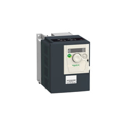
This Altivar 312 single phase variable speed drive has a rated power of 1.5kW, 3.2kVA, and a 200V to 240V AC rated output voltage. It is suitable for industrial machines such as materials handling and packaging, packing, textile machines, special machines, pumps and fans. It has a compact form-factor with 105mm width, allowing for a flexible and easy installation on a mounting plate. It also offers a snap-lock seal, status and faults display, a jog dial navigation button and an integrated EMC filter. It offers high readability of key parameters thanks to a bright LED 4-digit display. SoMove software compatibility enables saving and transfering of configurations to spare drive, reducing maintenance downtime.
Main
| Characteristic | Value(s) |
|---|---|
| Range of Product | Altivar 312 |
| Product or Component Type | Variable speed drive |
| Product destination | Asynchronous motors |
| Product Specific Application | Simple machine |
| Assembly style | With heat sink |
| Component name | ATV312 |
| Motor power kW | 1.5 kW |
| Maximum Horse Power Rating | 2 hp |
| [Us] rated supply voltage | 200...240 V - 15...10 % |
| Supply frequency | 50...60 Hz - 5...5 % |
| Phase | Single phase |
| Line current | 15.8 A 200 V, Isc = 1 kA 13.3 A 240 V |
| EMC filter | Integrated |
| Apparent power | 3.2 kVA |
| Maximum transient current | 12 A 60 s |
| Power dissipation in W | 90 W at nominal load |
| Speed range | 1â¦50 |
| Asynchronous motor control profile | Sensorless flux vector control with PWM type motor control signal Factory set : constant torque |
| Electrical connection | Al1, Al2, Al3, AOV, AOC, R1A, R1B, R1C, R2A, R2B, LI1...LI6 terminal 0.004 in² (2.5 mm²) AWG 14 L1, L2, L3, U, V, W, PA, PB, PA/+, PC/- terminal 0.008 in² (5 mm²) AWG 10 |
| Supply | Internal supply for logic inputs 19...30 V 100 mA overload and short-circuit protection Internal supply for reference potentiometer (2.2 to 10 kOhm) 10...10.8 V 10 mA overload and short-circuit protection |
| Communication Port Protocol | CANopen Modbus |
| IP degree of protection | IP20 on upper part without cover plate IP21 on connection terminals IP31 on upper part IP41 on upper part |
| Option card | Communication card CANopen daisy chain Communication card DeviceNet Communication card Fipio Communication card Modbus TCP Communication card Profibus DP |
Complementary
| Characteristic | Value(s) |
|---|---|
| Supply voltage limits | 170â¦264 V |
| Prospective line Isc | 1 kA |
| Continuous output current | 8 A 4 kHz |
| Output frequency | 0â¦500 Hz |
| Nominal switching frequency | 4 kHz |
| Switching frequency | 2...16 kHz adjustable |
| Transient overtorque | 170â¦200 % of nominal motor torque |
| Braking torque | 150 % 60 s with braking resistor 100 % with braking resistor continuously 150 % without braking resistor |
| Regulation loop | Frequency PI regulator |
| Motor slip compensation | Automatic whatever the load Adjustable Suppressable |
| Output voltage | <= power supply voltage |
| Tightening torque | Al1, Al2, Al3, AOV, AOC, R1A, R1B, R1C, R2A, R2B, LI1...LI6 5.3 lbf.in (0.6 N.m) L1, L2, L3, U, V, W, PA, PB, PA/+, PC/- 10.6 lbf.in (1.2 N.m) |
| Insulation | Electrical between power and control |
| Analogue input number | 3 |
| Analogue input type | AI1 configurable voltage 0...10 V 30 V max 30000 Ohm AI2 configurable voltage +/- 10 V 30 V max 30000 Ohm AI3 configurable current 0...20 mA 250 Ohm |
| Sampling duration | AI1, AI2, AI3 8 ms analog LI1...LI6 4 ms discrete |
| Response time | AOV, AOC 8 ms analog R1A, R1B, R1C, R2A, R2B 8 ms discrete |
| Linearity error | +/- 0.2 % output |
| Analogue output number | 1 |
| Analogue output type | AOC configurable current 0...20 mA 800 Ohm 8 bits AOV configurable voltage 0...10 V 470 Ohm 8 bits |
| Discrete input logic | Logic input not wired LI1...LI4), < 13 V Negative logic (source) LI1...LI6), > 19 V Positive logic (source) LI1...LI6), < 5 V, > 11 V |
| Discrete output number | 2 |
| Discrete output type | Configurable relay logic R1A, R1B, R1C) 1 NO + 1 NC - 100000 cycles Configurable relay logic R2A, R2B) NC - 100000 cycles |
| Minimum switching current | R1-R2 10 mA 5 V DC |
| Maximum switching current | R1-R2 2 A 250 V AC inductive, cos phi = 0.4 7 ms R1-R2 2 A 30 V DC inductive, cos phi = 0.4 7 ms R1-R2 5 A 250 V AC resistive, cos phi = 1 0 ms R1-R2 5 A 30 V DC resistive, cos phi = 1 0 ms |
| Discrete input number | 6 |
| Discrete input type | LI1...LI6) programmable 24 V, 0â¦100 mA PLC 3500 Ohm |
| Acceleration and deceleration ramps | S, U or customized Linear adjustable separately from 0.1 to 999.9 s |
| Braking to standstill | By DC injection |
| Protection type | Input phase breaks drive Line supply overvoltage and undervoltage safety circuits drive Line supply phase loss safety function, for three phases supply drive Motor phase breaks drive Overcurrent between output phases and earth (on power up only) drive Overheating protection drive Short-circuit between motor phases drive Thermal protection motor |
| Insulation resistance | >= 500 mOhm 500 V DC for 1 minute |
| Local signalling | 1 LED (red) for drive voltage Four 7-segment display units for CANopen bus status |
| Time constant | 5 ms for reference change |
| Frequency resolution | Analog input 0.1...100 Hz Display unit 0.1 Hz |
| Connector type | 1 RJ45 Modbus/CANopen |
| Physical interface | RS485 multidrop serial link |
| Transmission frame | RTU |
| Transmission Rate | 10, 20, 50, 125, 250, 500 kbps or 1 Mbps CANopen 4800, 9600 or 19200 bps Modbus |
| Number of addresses | 1â¦127 CANopen 1â¦247 Modbus |
| Number of drive | 127 CANopen 31 Modbus |
| Marking | CE |
| Operating position | Vertical +/- 10 degree |
| Outer dimension | 184 x 149 x 145 mm 200 x 180 x 144 mm 143 x 105 x 150 mm |
| Height | 5.6 in (143 mm) |
| Width | 4.2 in (107 mm) |
| Depth | 6.0 in (152 mm) |
| Product Weight | 4.0 lb(US) (1.8 kg) |

Variable Speed Drive Altivar ATV312 - 11kW - 25kVA - 397 W - 380..500 V - 3-Phase Supply

This Altivar 312 single phase variable speed drive has a rated power of 0.75kW, 1.8kVA, and a 200V to 240V AC rated output voltage. It is suitable for industrial machines such as materials handling and packaging, packing, textile machines, special machines, pumps and fans. It has a compact form-factor with 72mm width, allowing for a flexible and easy installation on a mounting plate. It also offers a snap-lock seal, status and faults display, a jog dial navigation button and an integrated EMC filter. It offers high readability of key parameters thanks to a bright LED 4-digit display. SoMove software compatibility enables saving and transfering of configurations to spare drive, reducing maintenance downtime.
Main
| Characteristic | Value(s) |
|---|---|
| Range of Product | Altivar 312 |
| Product or Component Type | Variable speed drive |
| Product destination | Asynchronous motors |
| Product Specific Application | Simple machine |
| Assembly style | With heat sink |
| Component name | ATV312 |
| Motor power kW | 0.75 kW |
| Maximum Horse Power Rating | 1 hp |
| [Us] rated supply voltage | 200...240 V - 15...10 % |
| Supply frequency | 50...60 Hz - 5...5 % |
| Phase | Single phase |
| Line current | 8.9 A 200 V, Isc = 1 kA 7.5 A 240 V |
| EMC filter | Integrated |
| Apparent power | 1.8 kVA |
| Maximum transient current | 7.2 A 60 s |
| Power dissipation in W | 60 W at nominal load |
| Speed range | 1â¦50 |
| Asynchronous motor control profile | Factory set : constant torque Sensorless flux vector control with PWM type motor control signal |
| Electrical connection | Al1, Al2, Al3, AOV, AOC, R1A, R1B, R1C, R2A, R2B, LI1...LI6 terminal 0.004 in² (2.5 mm²) AWG 14 L1, L2, L3, U, V, W, PA, PB, PA/+, PC/- terminal 0.004 in² (2.5 mm²) AWG 14 |
| Supply | Internal supply for logic inputs 19...30 V 100 mA overload and short-circuit protection Internal supply for reference potentiometer (2.2 to 10 kOhm) 10...10.8 V 10 mA overload and short-circuit protection |
| Communication Port Protocol | Modbus CANopen |
| IP degree of protection | IP20 on upper part without cover plate IP21 on connection terminals IP31 on upper part IP41 on upper part |
| Option card | Communication card CANopen daisy chain Communication card DeviceNet Communication card Fipio Communication card Modbus TCP Communication card Profibus DP |
Complementary
| Characteristic | Value(s) |
|---|---|
| Supply voltage limits | 170â¦264 V |
| Prospective line Isc | 1 kA |
| Continuous output current | 4.8 A 4 kHz |
| Output frequency | 0â¦500 Hz |
| Nominal switching frequency | 4 kHz |
| Switching frequency | 2...16 kHz adjustable |
| Transient overtorque | 170â¦200 % of nominal motor torque |
| Braking torque | 150 % 60 s with braking resistor 100 % with braking resistor continuously 150 % without braking resistor |
| Regulation loop | Frequency PI regulator |
| Motor slip compensation | Suppressable Adjustable Automatic whatever the load |
| Output voltage | <= power supply voltage |
| Tightening torque | Al1, Al2, Al3, AOV, AOC, R1A, R1B, R1C, R2A, R2B, LI1...LI6 5.3 lbf.in (0.6 N.m) L1, L2, L3, U, V, W, PA, PB, PA/+, PC/- 7.08 lbf.in (0.8 N.m) |
| Insulation | Electrical between power and control |
| Analogue input number | 3 |
| Analogue input type | AI1 configurable voltage 0...10 V 30 V max 30000 Ohm AI2 configurable voltage +/- 10 V 30 V max 30000 Ohm AI3 configurable current 0...20 mA 250 Ohm |
| Sampling duration | AI1, AI2, AI3 8 ms analog LI1...LI6 4 ms discrete |
| Response time | AOV, AOC 8 ms analog R1A, R1B, R1C, R2A, R2B 8 ms discrete |
| Linearity error | +/- 0.2 % output |
| Analogue output number | 1 |
| Analogue output type | AOC configurable current 0...20 mA 800 Ohm 8 bits AOV configurable voltage 0...10 V 470 Ohm 8 bits |
| Discrete input logic | Logic input not wired LI1...LI4), < 13 V Negative logic (source) LI1...LI6), > 19 V Positive logic (source) LI1...LI6), < 5 V, > 11 V |
| Discrete output number | 2 |
| Discrete output type | Configurable relay logic R1A, R1B, R1C) 1 NO + 1 NC - 100000 cycles Configurable relay logic R2A, R2B) NC - 100000 cycles |
| Minimum switching current | R1-R2 10 mA 5 V DC |
| Maximum switching current | R1-R2 2 A 250 V AC inductive, cos phi = 0.4 7 ms R1-R2 2 A 30 V DC inductive, cos phi = 0.4 7 ms R1-R2 5 A 250 V AC resistive, cos phi = 1 0 ms R1-R2 5 A 30 V DC resistive, cos phi = 1 0 ms |
| Discrete input number | 6 |
| Discrete input type | LI1...LI6) programmable 24 V, 0â¦100 mA PLC 3500 Ohm |
| Acceleration and deceleration ramps | Linear adjustable separately from 0.1 to 999.9 s S, U or customized |
| Braking to standstill | By DC injection |
| Protection type | Input phase breaks drive Line supply overvoltage and undervoltage safety circuits drive Line supply phase loss safety function, for three phases supply drive Motor phase breaks drive Overcurrent between output phases and earth (on power up only) drive Overheating protection drive Short-circuit between motor phases drive Thermal protection motor |
| Insulation resistance | >= 500 mOhm 500 V DC for 1 minute |
| Local signalling | 1 LED (red) for drive voltage Four 7-segment display units for CANopen bus status |
| Time constant | 5 ms for reference change |
| Frequency resolution | Analog input 0.1...100 Hz Display unit 0.1 Hz |
| Connector type | 1 RJ45 Modbus/CANopen |
| Physical interface | RS485 multidrop serial link |
| Transmission frame | RTU |
| Transmission Rate | 10, 20, 50, 125, 250, 500 kbps or 1 Mbps CANopen 4800, 9600 or 19200 bps Modbus |
| Number of addresses | 1â¦127 CANopen 1â¦247 Modbus |
| Number of drive | 127 CANopen 31 Modbus |
| Marking | CE |
| Operating position | Vertical +/- 10 degree |
| Height | 5.7 in (145 mm) |
| Width | 2.8 in (72 mm) |
| Depth | 5.6 in (142 mm) |
| Product Weight | 3.3 lb(US) (1.5 kg) |
ANALOG OUTPUT MODULE, 5-24 VDC, 125-225 MA, 4 CHANNEL

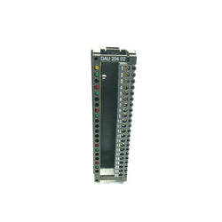
This connection sub-base is part of the Modicon ABE7 range, an offer of IP20 sub-bases for Telefast pre-wired system. It is for distribution of 8 analog input channels. It is a sub-base with a control circuit voltage of 24V DC. The distributed analog input channels are isolated from one another. It is furnished with screw type terminals for electrical connection and 25-way SUB-D connection to Programmable Logic Controllers (PLC). It is an IP20 rated product. It weighs 0.41kg. It is suitable for all types of industrial applications. This product is certified by LROS, DNV, UL, GL, BV and CSA. It meets CSA C22.2, IEC 61131 and UL 508 standards. This connection sub-base is suitable for use with Modicon X80 IO modules such as BMXAMI0800, BMXAMI0810 and BMEAHI0812. It is delivered in 1 package (PCE type). It can be fixed by clips (35mm symmetrical DIN rail) and screws (solid plate with fixing kit). Modicon ABE7 means greater simplicity to rationalise wiring in automation system equipment. Pre-wired system enabling connection and adaptation of control signals of PLC cards equipped with HE10 connectors.
Main
| Characteristic | Value(s) |
|---|---|
| Range of Product | Modicon ABE7 |
| Product or Component Type | Connection sub-base for counter and analogue channels |
| Number of channels | 8 |
| Connections - terminals | Screw type terminals, 1 x 0.09...1 x 1.5 mm² AWG 28...AWG 16) flexible with cable end Screw type terminals, 1 x 0.14...1 x 2.5 mm² AWG 26...AWG 12) solid Screw type terminals, 1 x 0.14...1 x 2.5 mm² AWG 26...AWG 14) flexible without cable end Screw type terminals, 2 x 0.09...2 x 0.75 mm² AWG 28...AWG 20) flexible with cable end Screw type terminals, 2 x 0.2...2 x 2.5 mm² AWG 24...AWG 14) solid |
Complementary
| Characteristic | Value(s) |
|---|---|
| Function of module | Isolated analogue input Premium |
| [Uc] control circuit voltage | 24 V DC |
| Connection to PLC | SUB-D 25 |
| Fixing mode | By clips (35 mm symmetrical DIN rail) By screws (solid plate with fixing kit) |
| [Ui] rated insulation voltage | 2000 V terminals/mounting rails |
| Installation category | II IEC 60664-1 |
| Tightening torque | 5.3 lbf.in (0.6 N.m) flat à 3.5 mm |
| Product Weight | 0.90 lb(US) (0.41 kg) |

Main
| Characteristic | Value(s) |
|---|---|
| Range of Product | Modicon Quantum automation platform |
| Product or Component Type | Unity processor |
Complementary
| Characteristic | Value(s) |
|---|---|
| Clock frequency | 266 MHz |
| Number of slots | 16 6 2 10 4 |
| Number of racks | 2 - local |
| Number of distributed I/O station | 63 1 1 Modbus Plus |
| Number of remote I/O station | 31 - 2 S908 remote I/O 31 - 2 ethernet Quantum remote I/O 31 - 2 ethernet X80 remote I/O |
| Discrete I/O number | 8000 inputs, 8000 outputs - distributed - per network Modbus Plus Unlimited (26 slots max) - local Unlimited (31 drops of 28 slots max) - ethernet remote I/O 31744 inputs, 31744 outputs - S908 remote I/O |
| Analogue I/O number | 500 inputs, 500 outputs - distributed - per network Modbus Plus Unlimited (26 slots max) - local Unlimited (31 drops of 28 slots max) - ethernet remote I/O 1984 inputs,1984 outputs - remote |
| Application specific I/O | Counter Accurate time stamping Serial link High-speed interrupt inputs |
| Communication Service | Ethernet router |
| Number of optional modules | 6 Ethernet, Modbus, Modbus Plus, Profibus DP, Sy/Max) |
| Maximum number of connections | 1 USB 2 AS-Interface - distributed 4 AS-Interface - remote 6 Ethernet TCP/IP - local 6 Modbus Plus - local 6 Profibus DP - local 1 Modbus RS232/485 Modbus/ASCII) |
| Integrated connection type | 1 Modbus Plus 1 Ethernet TCP/IP 1 Modbus 1 USB |
| Checks | Process control |
| Memory description | Expandable 7168 kB - program with PCMCIA card Expandable 8 MB - file storage with PCMCIA card Internal RAM 3072 kB |
| Switch Function | Key switch memory port on/off |
| Application structure | 1 cyclic/periodic master task - 1 periodic fast task - 128 I/O interrupt tasks - 128 interrupt tasks - 32 timer interrupt tasks - 4 auxiliary tasks - |
| Number of instructions per ms | 10.28 Kinst/ms 100 % Boolean 10.07 Kinst/ms 65 % Boolean and 35 % numerical |
| System overhead | 0.2 ms fast task 1 ms master task |
| Bus current requirement | 2760 mA |
| Local signalling | 1 LED (green) for Ethernet activity (COM) 1 LED (red) for Ethernet collision |
| Electrical connection | 1 female connector SUB-D 9 for connecting to the Modbus Plus network 1 connector RJ45 for connecting Ethernet network 1 connector RJ45 for connecting Modbus bus |
DIN rail power supply unit 24 V DC/1 A, primary-switched mode, slim design

"4 in 1" three-phase semiconductor reversing contactor with 24 V DC input, 9 A output current, emergency stop function, and adjustable overload switching.

| Product | |
| Article Number (Market Facing Number) | 3SK11111AW20 | 3SK11111AW20 |
| Product Description | |
| Product family | SIRIUS 3SK1 Standard basic units |
| Product Lifecycle (PLM) | PM300:Active Product |
| Additional Product Information | |
| EAN | 4011209913516 |
| UPC | Not available |
| Commodity Code | 85371098 |
| LKZ_FDB/ CatalogID | CC-IC10 |
| Product Group | 3761 |
| Group Code | R711 |
| Country of origin | Germany |
| SCIP number | Not available |
| Delivery information | |
| Net Weight (lb) | 0.582 lb |
| Package size unit of measure | in |
| Packaging Quantity | 1 |

ABB EcoSolutions
Material Compliance
Environmental
Ordering
Dimensions
Container Information
Additional Information
Technical
Certificates and Declarations
External Classifications and Standards

3.5 Touch Panel

G-Series Servo Drive Pulse input type 800 W 1~ 200 VAC
Ethernet Modules SPECIAL SEMICONDUCTOR JS
DeviceNet Module, functions as either a master or a slave, 2,048 I/O points, multi-drop & T-branch connections, Baud rate: 500 Kbps, 250 Kbps, or 125 Kbps, 64 nodes max, 24/DC
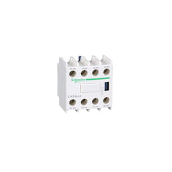
TeSys Deca instantaneous auxiliary contact block, for contactors LC1D, LC1F and control relays CAD. It provides 4NO contacts rated up to 10A/690V AC, connection by screw clamp terminals. Clip-on front mounting, it procures high reliability and durability. TeSys Deca contactors have been designed for perfect integration into control systems. Multi standards certified (IEC, UL, CSA, CCC, EAC). TeSys Deca contactors offer quick simple setup, while maintaining a compact size. Contactors have both horsepower and Kw motor rating for international acceptance. An extennsive line of accessories makes it easy to meet the requirements of most applications. These contactors have UL, CSA, GOST, RINA, BV, CCC, DNV, GL, LROS certifications.
Main
| Characteristic | Value(s) |
|---|---|
| Range | TeSys TeSys Deca |
| product name | TeSys Deca |
| Product or Component Type | Auxiliary contact block |
| Device short name | LADN |
| Range compatibility | TeSys D CAD TeSys D LC1D TeSys F LC1F TeSys F CR1F TeSys Deca CAD TeSys Deca LC1D |
| Mounting Location | Front |
| Pole contact composition | 4 NO |
| Contacts operation | Instantaneous |
| [Ue] rated operational voltage | 690 V AC 25...400 Hz |
| [Ie] rated operational current | 6 A at 120 V AC-15 1.04 A at 690 V AC-15 0.55 A at 125 V DC-13 0.1 A at 600 V DC-13 |
| [Ui] rated insulation voltage | 690 V IEC 60947-5-1 600 V UL 600 V CSA |
| [Ith] conventional free air thermal current | 10 A (at 140 °F (60 °C)) |
| Standards | EN/IEC 60947-5-1 GB/T 14048.5 EN 50012 UL 60947-5-1 CSA C22.2 No 60947-5-1 IEC 60335-1:Clause 30.2 IEC 60335-2-40:Annex JJ UL 60335-2-40:Annex JJ |
| Product Certifications | CB Scheme UL CSA CCC EAC UKCA |
Complementary
| Characteristic | Value(s) |
|---|---|
| Irms rated making capacity | 140 A AC conforming to IEC 60947-5-1 250 A DC conforming to IEC 60947-5-1 |
| Permissible short-time rating | 100 A 140 °F (60 °C) 1 s 120 A 140 °F (60 °C) 500 ms 140 A 140 °F (60 °C) 100 ms |
| Protection type | GG fuse 10 A |
| Mechanical durability | 30 Mcycles |
| Minimum switching current | 5 mA |
| Minimum switching voltage | 17 V |
| Non-overlap time | 1.5 ms on de-energisation no overlap between NC and NO contact 1.5 ms on energisation no overlap between NC and NO contact |
| Insulation resistance | > 10 MOhm |
| Connections - terminals | screw clamp terminals 1 0.002â¦0.006 in² (1â¦4 mm²)flexible with cable end screw clamp terminals 1 0.002â¦0.006 in² (1â¦4 mm²)flexible without cable end screw clamp terminals 2 0.002â¦0.004 in² (1â¦2.5 mm²)flexible with cable end screw clamp terminals 2 0.002â¦0.006 in² (1â¦4 mm²)flexible without cable end screw clamp terminals 1 0.002â¦0.006 in² (1â¦4 mm²)rigid without cable end screw clamp terminals 2 0.002â¦0.006 in² (1â¦4 mm²)rigid without cable end |
| Tightening torque | 15.05 lbf.in (1.7 N.m) flat à 6 mm 15.05 lbf.in (1.7 N.m) Philips No 2 15.05 lbf.in (1.7 N.m) pozidriv No 2 |
| Height | 1.9 in (48 mm) |
| Width | 1.7 in (44 mm) |
| Depth | 1.7 in (42 mm) |
| Product Weight | 0.11 lb(US) (0.05 kg) |
| color | Dark grey |

TeSys Deca contactor, 3 poles (3NO), for motor control applications up to 38A/690V AC-3/3e (18.5kW@400V). They can be used to create motor starters for almost any type of application. It provides a 24V DC coil with transient suppressor module, 1NO+1NC built-in auxiliary contacts (NC mirror certified), connection by screw clamp terminals. For operating rates until 3600 cycles/hour and environments until 60°C, it procures high reliability and durability. Compact (45mm width), DIN-rail mounting or screw fixing. Contactor is rated for 10HP at 200 to 208VAC, 10HP at 240VAC, 20HP at 480VAC and 25HP at 600VAC three phase. Multi standards certified (IEC, UL, CSA, CCC, EAC, Marine). When used with a 480VAC up to 60A circuit breaker, this contactor can have a SCCR up to 85kA. When used with up to a 600VAC 80A Class J or CC fuse, this contactor can have a SCCR up to 100kA. Contactor is supplied with a 24 VDC coil with transient suppressor module. Contactor has one normally open and one normally closed auxiliary contact built-in as standard. The NC contact is mirror certified. Screw clamp terminals are used for load and auxiliary connections. An extensive line of accessories makes it easy to meet the requirements of most applications. The contactor is 3.35 inches tall, 1.77 inches wide and 3.98 inches deep. It weighs 1.19 lbs. Contactor is certified to UL, CSA, IEC, CCC, EAC and Marine standards.
Main
| Characteristic | Value(s) |
|---|---|
| Range | TeSys TeSys Deca |
| Range of Product | TeSys Deca |
| Product or Component Type | Contactor |
| Device short name | LC1D |
| Contactor application | Resistive load Motor control |
| Utilisation category | AC-4 AC-1 AC-3 AC-3e |
| Poles description | 3P |
| [Ue] rated operational voltage | Power circuit <= 690 V AC 25...400 Hz Power circuit <= 300 V DC |
| [Ie] rated operational current | 50 A (at <140 °F (60 °C)) at <= 440 V AC AC-1 for power circuit 38 A (at <140 °F (60 °C)) at <= 440 V AC AC-3 for power circuit 38 A (at <140 °F (60 °C)) at <= 440 V AC AC-3e for power circuit |
| [Uc] control circuit voltage | 24 V DC |
Complementary
| Characteristic | Value(s) |
|---|---|
| Motor power kW | 18.5 kW at 500 V AC 50/60 Hz (AC-3) 18.5 kW at 660...690 V AC 50/60 Hz (AC-3) 7.5 kW at 400 V AC 50/60 Hz (AC-4) 18.5 kW at 380...400 V AC 50/60 Hz (AC-3) 9 kW at 220...230 V AC 50/60 Hz (AC-3) 18.5 kW at 415...440 V AC 50/60 Hz (AC-3) 18.5 kW at 500 V AC 50/60 Hz (AC-3e) 18.5 kW at 660...690 V AC 50/60 Hz (AC-3e) 18.5 kW at 380...400 V AC 50/60 Hz (AC-3e) 9 kW at 220...230 V AC 50/60 Hz (AC-3e) 18.5 kW at 415...440 V AC 50/60 Hz (AC-3e) |
| Maximum Horse Power Rating | 10 hp at 230/240 V AC 50/60 Hz for 3 phase motors 10 hp at 200/208 V AC 50/60 Hz for 3 phase motors 5 hp at 240 V AC 50/60 Hz for 1 phase motors 20 hp at 480 V AC 50/60 Hz for 3 phase motors 25 hp at 600 V AC 50/60 Hz for 3 phase motors |
| Compatibility code | LC1D |
| Pole contact composition | 3 NO |
| Protective cover | With |
| [Ith] conventional free air thermal current | 10 A (at 140 °F (60 °C)) for signalling circuit 50 A (at 140 °F (60 °C)) for power circuit |
| Irms rated making capacity | 140 A AC for signalling circuit conforming to IEC 60947-5-1 250 A DC for signalling circuit conforming to IEC 60947-5-1 550 A at 440 V for power circuit conforming to IEC 60947 |
| Rated breaking capacity | 550 A at 440 V for power circuit conforming to IEC 60947 |
| [Icw] rated short-time withstand current | 60 A 104 °F (40 °C) - 10 min for power circuit 430 A 104 °F (40 °C) - 1 s for power circuit 150 A 104 °F (40 °C) - 1 min for power circuit 310 A 104 °F (40 °C) - 10 s for power circuit 100 A - 1 s for signalling circuit 120 A - 500 ms for signalling circuit 140 A - 100 ms for signalling circuit |
| Associated fuse rating | 10 A gG for signalling circuit conforming to IEC 60947-5-1 63 A gG at <= 690 V coordination type 1 for power circuit 63 A gG at <= 690 V coordination type 2 for power circuit |
| Average impedance | 2 mOhm - Ith 50 A 50 Hz for power circuit |
| Power dissipation per pole | 5 W AC-1 3 W AC-3 3 W AC-3e |
| [Ui] rated insulation voltage | Power circuit 600 V CSA Power circuit 600 V UL Signalling circuit 690 V IEC 60947-1 Signalling circuit 600 V CSA Signalling circuit 600 V UL Power circuit 690 V IEC 60947-4-1 |
| Overvoltage category | III |
| pollution degree | 3 |
| [Uimp] rated impulse withstand voltage | 6 kV IEC 60947 |
| Safety reliability level | B10d = 1369863 cycles contactor with nominal load EN/ISO 13849-1 B10d = 20000000 cycles contactor with mechanical load EN/ISO 13849-1 |
| Mechanical durability | 30 Mcycles |
| Electrical durability | 1.4 Mcycles 50 A AC-1 <= 440 V 1.4 Mcycles 38 A AC-3 <= 440 V 1.4 Mcycles 38 A AC-3e <= 440 V |
| Control circuit type | DC standard |
| Coil technology | Built-in bidirectional peak limiting diode suppressor |
| Control circuit voltage limits | 0.1...0.25 Uc (-40â¦158 °F (-40â¦70 °C)):drop-out DC 0.7...1.25 Uc (-40â¦140 °F (-40â¦60 °C)):operational DC 1...1.25 Uc (140â¦158 °F (60â¦70 °C)):operational DC |
| Inrush power in W | 5.4 W 68 °F (20 °C)) |
| Hold-in power consumption in W | 5.4 W 68 °F (20 °C) |
| Operating time | 20 ±20 % ms opening 63 ±15 % ms closing |
| Time constant | 28 ms |
| Maximum operating rate | 3600 cyc/h at 60 °C |
| Connections - terminals | Control circuit: screw clamp terminals 2 0.002â¦0.004 in² (1â¦2.5 mm²) - cable stiffness: flexible with cable end Control circuit: screw clamp terminals 1 0.002â¦0.006 in² (1â¦4 mm²) - cable stiffness: flexible without cable end Control circuit: screw clamp terminals 2 0.002â¦0.006 in² (1â¦4 mm²) - cable stiffness: flexible without cable end Control circuit: screw clamp terminals 1 0.002â¦0.006 in² (1â¦4 mm²) - cable stiffness: flexible with cable end Control circuit: screw clamp terminals 1 0.002â¦0.006 in² (1â¦4 mm²) - cable stiffness: solid without cable end Control circuit: screw clamp terminals 2 0.002â¦0.006 in² (1â¦4 mm²) - cable stiffness: solid without cable end Power circuit: screw clamp terminals 1 0.004â¦0.02 in² (2.5â¦10 mm²) - cable stiffness: flexible without cable end Power circuit: screw clamp terminals 2 0.004â¦0.02 in² (2.5â¦10 mm²) - cable stiffness: flexible without cable end Power circuit: screw clamp terminals 1 0.002â¦0.02 in² (1â¦10 mm²) - cable stiffness: flexible with cable end Power circuit: screw clamp terminals 2 0.002â¦0.009 in² (1.5â¦6 mm²) - cable stiffness: flexible with cable end Power circuit: screw clamp terminals 1 0.002â¦0.02 in² (1.5â¦10 mm²) - cable stiffness: solid without cable end Power circuit: screw clamp terminals 2 0.004â¦0.02 in² (2.5â¦10 mm²) - cable stiffness: solid without cable end |
| Tightening torque | Control circuit 15.05 lbf.in (1.7 N.m) screw clamp terminals flat à 6 mm Control circuit 15.05 lbf.in (1.7 N.m) screw clamp terminals Philips No 2 Power circuit 22.1 lbf.in (2.5 N.m) screw clamp terminals flat à 6 mm Power circuit 22.1 lbf.in (2.5 N.m) screw clamp terminals Philips No 2 Control circuit 15.05 lbf.in (1.7 N.m) screw clamp terminals pozidriv No 2 Power circuit 22.1 lbf.in (2.5 N.m) screw clamp terminals pozidriv No 2 |
| Auxiliary contact composition | 1 NO + 1 NC |
| Auxiliary contacts type | Mechanically linked 1 NO + 1 NC IEC 60947-5-1 Mirror contact 1 NC IEC 60947-4-1 |
| Signalling circuit frequency | 25...400 Hz |
| Minimum switching voltage | 17 V for signalling circuit |
| Minimum switching current | 5 mA for signalling circuit |
| Insulation resistance | > 10 MOhm for signalling circuit |
| Non-overlap time | 1.5 ms on de-energisation between NC and NO contact 1.5 ms on energisation between NC and NO contact |
| Mounting Support | Plate Rail |