
 1 year warranty

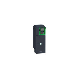
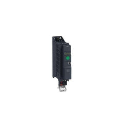
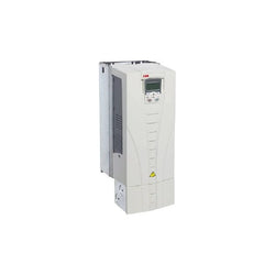
This Altivar Process ATV600 variable speed drive can feed 3-phase synchronous and asynchronous power motors. It features 3 built-in RJ45 communication ports as standard, 1 Ethernet port, 2 serial ports. It works at a rated supply voltage from 380V to 480V AC. This drive provides up to 30% energy saving when on standby due to the innovative ââStop and Goââoperation without additional costs. It is suitable for motors with power rating up to 18.5kW / 25hp for applications requiring slight overload (up to 120%). It is suitable for motors with power rating up to 15kW / 20hp for applications requiring significant overload (up to 150%). It weighs 14.2kg and its dimensions are, 211mm wide, 546mm high, 232mm deep. This drive is focused on fluids management processing and energy saving, it offers extensive flexibility in water and wastewater, mining, minerals and metals, oil and gas and food and beverage applications. Accessories (fan kit, graphic display terminal) and options (I/O expansion modules, communication modules, EMC input filters) are available with Altivar Process ATV600 drives, depending on the drive rating. It is designed to be mounted in vertical position (+/- 10 °) on a wall. This new concept of drives meets the major needs of process and utilities in terms of equipment efficiency and total cost of ownership by supporting the energy management, asset management and also the overall performance of the process.
Main
| Characteristic | Value(s) |
|---|---|
| Range of Product | Altivar Process ATV600 |
| Product Specific Application | Process and utilities |
| Product or Component Type | Variable speed drive |
| Variant | Standard version |
| Device short name | ATV630 |
| Mounting Mode | Wall mount |
| Communication Port Protocol | Modbus TCP Modbus serial Ethernet |
| [Us] rated supply voltage | 380...480 V - 15...10 % |
| [Us] rated supply voltage | 380...480 V |
| Relative symmetric mains voltage tolerance | 10 % |
| Relative symmetric network frequency tolerance | 5 % |
| nominal output current | 39.2 A |
| IP degree of protection | IP21 |
| Product destination | Asynchronous motors Synchronous motors |
| EMC filter | Integrated 164.04 ft (50 m) IEC 61800-3 category C2 Integrated 492.1 ft (150 m) IEC 61800-3 category C3 |
| IP degree of protection | IP21IEC 61800-5-1 IP21IEC 60529 |
| Degree of protection | UL type 1 UL 508C |
| type of cooling | Forced convection |
| Supply frequency | 50...60 Hz - 5...5 % |
| Motor power kW | 18.5 kW normal duty) 15 kW heavy duty) |
| Maximum Horse Power Rating | 25 hp normal duty 20 hp heavy duty |
| Line current | 33.4 A 380 V normal duty) 28.9 A 480 V normal duty) 27.7 A 380 V heavy duty) 24.4 A 480 V heavy duty) |
| Continuous output current | 39.2 A 4 kHz normal duty 31.7 A 4 kHz heavy duty |
| Speed drive output frequency | 0.1â¦500 Hz |
| Safety function | STO (safe torque off) SIL 3 |
| Option card | Slot A communication module, Profibus DP V1 Slot A communication module, PROFINET Slot A communication module, DeviceNet Slot A communication module, Modbus TCP/EtherNet/IP Slot A communication module, CANopen daisy chain RJ45 Slot A communication module, CANopen SUB-D 9 Slot A communication module, CANopen screw terminals Slot A/slot B digital and analog I/O extension module Slot A/slot B output relay extension module Slot A communication module, Ethernet IP/Modbus TCP/MD-Link communication module, BACnet MS/TP communication module, Ethernet Powerlink |
Complementary
| Characteristic | Value(s) |
|---|---|
| Discrete input number | 8 |
| Discrete input type | DI7, DI8 programmable as pulse input 0â¦30 kHz, 24 V DC <= 30 V) |
| Discrete input logic | 16 preset speeds |
| Discrete output number | 0 |
| Discrete output type | Relay outputs R1A, R1B, R1C 250 V AC 3000 mA Relay outputs R1A, R1B, R1C 30 V DC 3000 mA Relay outputs R2A, R2C 250 V AC 5000 mA Relay outputs R2A, R2C 30 V DC 5000 mA Relay outputs R3A, R3C 250 V AC 5000 mA Relay outputs R3A, R3C 30 V DC 5000 mA |
| Analogue input number | 3 |
| Analogue input type | AI1, AI2, AI3 software-configurable voltage 0...10 V DC 31.5 kOhm 12 bits AI1, AI2, AI3 software-configurable current 0...20 mA 250 Ohm 12 bits AI2 voltage analog input - 10...10 V DC 31.5 kOhm 12 bits |
| Analogue output number | 2 |
| Analogue output type | Software-configurable voltage AQ1, AQ2 0...10 V DC 470 Ohm 10 bits Software-configurable current AQ1, AQ2 0...20 mA 10 bits Software-configurable current DQ-, DQ+ 30 V DC Software-configurable current DQ-, DQ+ 100 mA |
| Relay output number | 3 |
| Relay output type | Configurable relay logic R1 fault relay NO/NC 100000 cycles Configurable relay logic R2 sequence relay NO 100000 cycles Configurable relay logic R3 sequence relay NO 100000 cycles |
| Maximum switching current | Relay output R1, R2, R3 resistive, cos phi = 1 3 A 250 V AC Relay output R1, R2, R3 resistive, cos phi = 1 3 A 30 V DC Relay output R1, R2, R3 inductive, cos phi = 0.4 7 ms 2 A 250 V AC Relay output R1, R2, R3 inductive, cos phi = 0.4 7 ms 2 A 30 V DC |
| Minimum switching current | Relay output R1, R2, R3 5 mA 24 V DC |
| Phase | 3 phase |
| Physical interface | Ethernet 2-wire RS 485 |
| Method of access | Slave Modbus TCP |
| Transmission Rate | 10, 100 Mbits 4800 bps, 9600 bps, 19200 bps, 38.4 Kbps |
| Transmission frame | RTU |
| Output voltage | <= power supply voltage |
| Permissible temporary current boost | 1.1 x In 60 s normal duty) 1.5 x In 60 s heavy duty) |
| Data format | 8 bits, configurable odd, even or no parity |
| Type of polarization | No impedance |
| Frequency resolution | Display unit 0.1 Hz Analog input 0.012/50 Hz |
| Electrical connection | Control removable screw terminals 0.5...1.5 mm² AWG 20...AWG 16 Line side screw terminal 10...16 mm² AWG 8...AWG 6 Motor screw terminal 10...16 mm² AWG 8...AWG 6 |
| Connector type | RJ45 on the remote graphic terminal)Ethernet/Modbus TCP RJ45 on the remote graphic terminal)Modbus serial |
| Exchange mode | Half duplex, full duplex, autonegotiation Ethernet/Modbus TCP |
| Number of addresses | 1â¦247 Modbus serial |
| Supply | External supply for digital inputs 24 V DC 19â¦30 V), <1.25 mA overload and short-circuit protection Internal supply for reference potentiometer (1 to 10 kOhm) 10.5 V DC +/- 5 %, <10 mA overload and short-circuit protection Internal supply for digital inputs and STO 24 V DC 21â¦27 V), <200 mA overload and short-circuit protection |
| Local signalling | 3 LEDs for local diagnostic 3 LEDs (dual colour) for embedded communication status 4 LEDs (dual colour) for communication module status 1 LED (red) for presence of voltage |
| Input compatibility | DI1...DI6 discrete input level 1 PLC IEC 61131-2 DI5, DI6 discrete input level 1 PLC IEC 65A-68 STOA, STOB discrete input level 1 PLC IEC 61131-2 |
| Discrete input logic | Positive logic (source) DI1...DI8), < 5 V, > 11 V Negative logic (sink) DI1...DI8), > 16 V, < 10 V |
| Sampling duration | 2 ms +/- 0.5 ms DI1...DI4) - discrete input 5 ms +/- 1 ms DI5, DI6) - discrete input 5 ms +/- 0.1 ms AI1, AI2, AI3) - analog input 10 ms +/- 1 ms AO1) - analog output |
| Accuracy | +/- 0.6 % AI1, AI2, AI3 for a temperature variation 60 °C analog input +/- 1 % AO1, AO2 for a temperature variation 60 °C analog output |
| Linearity error | AI1, AI2, AI3 +/- 0.15 % of maximum value analog input AO1, AO2 +/- 0.2 % analog output |
| Refresh time | Relay output R1, R2, R3)5 ms +/- 0.5 ms) |
| Isolation | Between power and control terminals |
| Discrete and process manufacturing | Building - HVAC compressor centrifugal Food and beverage processing other application Mining mineral and metal fan Mining mineral and metal pump Oil and gas fan Water and waste water other application Building - HVAC screw compressor Food and beverage processing pump Food and beverage processing fan Food and beverage processing atomization Oil and gas electro submersible pump (ESP) Oil and gas water injection pump Oil and gas jet fuel pump Oil and gas compressor for refinery Water and waste water centrifuge pump Water and waste water positive displacement pump Water and waste water electro submersible pump (ESP) Water and waste water screw pump Water and waste water lobe compressor Water and waste water screw compressor Water and waste water compressor centrifugal Water and waste water fan Water and waste water conveyor Water and waste water mixer |
| Power range | 15â¦25 kW 380â¦440 V 3 phase 15â¦25 kW 480â¦500 V 3 phase |
| Enclosure mounting | Wall mounted |
| 4 quadrant operation possible | False |
| Asynchronous motor control profile | Optimized torque mode Variable torque standard Constant torque standard |
| Synchronous motor control profile | Permanent magnet motor Synchronous reluctance motor |
| Maximum output frequency | 500 kHz |
| Acceleration and deceleration ramps | Linear adjustable separately from 0.01...9999 s |
| Motor slip compensation | Automatic whatever the load Adjustable Not available in permanent magnet motor law Can be suppressed |
| Switching frequency | 2...12 kHz adjustable 4...12 kHz with derating factor |
| Nominal switching frequency | 4 kHz |
| Braking to standstill | By DC injection |
| Brake chopper integrated | False |
| Maximum Input Current per Phase | 33.4 A |
| Maximum output voltage | 480.0 V |
| Apparent power | 24 kVA 480 V normal duty) 20.3 kVA 480 V heavy duty) |
| Maximum transient current | 43.1 A 60 s normal duty) 47.6 A 60 s heavy duty) |
| Network Frequency | 50-60 Hz |
| Prospective line Isc | 50 kA |
| Base load current at high overload | 31.7 A |
| Base load current at low overload | 39.2 A |
| Power dissipation in W | Natural convection 67 W 380 V 4 kHz Forced convection 460 W 380 V 4 kHz |
| With safety function Safely Limited Speed (SLS) | False |
| With safety function Safe brake management (SBC/SBT) | False |
| With safety function Safe Operating Stop (SOS) | False |
| With safety function Safe Position (SP) | False |
| With safety function Safe programmable logic | False |
| With safety function Safe Speed Monitor (SSM) | False |
| With safety function Safe Stop 1 (SS1) | False |
| With sft fct Safe Stop 2 (SS2) | False |
| With safety function Safe torque off (STO) | True |
| With safety function Safely Limited Position (SLP) | False |
| With safety function Safe Direction (SDI) | False |
| Protection type | Thermal protection motor Safe torque off motor Motor phase break motor Thermal protection drive Safe torque off drive Overheating drive Overcurrent between output phases and earth drive Overload of output voltage drive Short-circuit protection drive Motor phase break drive Overvoltages on the DC bus drive Line supply overvoltage drive Line supply undervoltage drive Line supply phase loss drive Overspeed drive Break on the control circuit drive |
| Quantity per Set | 1 |
| Width | 8.3 in (211 mm) |
| Height | 21.5 in (546 mm) |
| Depth | 9.1 in (232 mm) |
| Product Weight | 31.3 lb(US) (14.2 kg) |

Variable Speed Drive ATV630 - 15kW/20hp - 380...480V - IP21/UL type 1
| Product | |
| Article Number (Market Facing Number) | 6SL32550AA004CA1 | 6SL32550AA004CA1 |
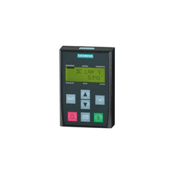
| Product Description | SINAMICS G120 Basic Operator Panel (BOP-2) |
| Product family | Ordering Data Overview |
| Product Lifecycle (PLM) | PM300:Active Product |
| Additional Product Information | |
| EAN | 4019169458085 |
| UPC | Not available |
| Commodity Code | 85049090 |
| LKZ_FDB/ CatalogID | D11.1SD |
| Product Group | 9791 |
| Group Code | R220 |
| Country of origin | Great Britain |
| SCIP number | Not available |
| Delivery information | |
| Net Weight (lb) | 0.309 lb |
| Package size unit of measure | Inch |
| Packaging Quantity | 1 |

| Product | |
| Article Number (Market Facing Number) | 6SL31000BE255AB0 | 6SL31000BE255AB0 |
| Product Description | SINAMICS S120 ACTIVE INTERFACE MODULE FOR 55KW ACTIVE LINE MODULE INPUT: 3AC 380-480V, 50/60HZ |
| Product family | Ordering Data Overview |
| Product Lifecycle (PLM) | PM300:Active Product |
| Additional Product Information | |
| EAN | 4042948662953 |
| UPC | 662643432763 |
| Commodity Code | 85363030 |
| LKZ_FDB/ CatalogID | D21MC |
| Product Group | 9617 |
| Group Code | R220 |
| Country of origin | Germany |
| SCIP number | ef578b0a-7ea7-48d5-a8df-68a002a67078 |
| Delivery information | |
| Net Weight (lb) | 52.911 lb |
| Package size unit of measure | Not available |
| Packaging Quantity | 1 |
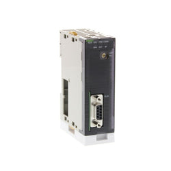
Profibus-DP master module, 9.6 to 12Mbit/s, 7k words I/O and 25 words CIO, 9-pin female sub-D connector, rotary switch, 400 mA at 5/DC
Main
| Characteristic | Value(s) |
|---|---|
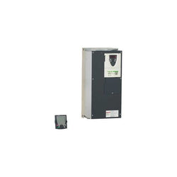
| Range of Product | Altivar 71 |
| Product or Component Type | Variable speed drive |
| Product Specific Application | Complex, high-power machines |
| Component name | ATV71 |
| Motor power kW | 37 kW, 3 phase 380...480 V |
| Maximum Horse Power Rating | 50 hp, 3 phase 380...480 V |
| Maximum motor cable length | 328.08 ft (100 m) shielded cable 656.2 ft (200 m) unshielded cable |
| power supply voltage | 380...480 V - 15...10 % |
| Phase | 3 phase |
| Line current | 69 A 480 V 3 phase 37 kW / 50 hp 84 A 380 V 3 phase 37 kW / 50 hp |
| EMC filter | Integrated |
| Assembly style | With heat sink |
| Apparent power | 55.3 kVA 380 V 3 phase 37 kW / 50 hp |
| Prospective line Isc | 22 kA 3 phase |
| Nominal output current | 65 A 2.5 kHz 460 V 3 phase 37 kW / 50 hp 79 A 2.5 kHz 380 V 3 phase 37 kW / 50 hp |
| Maximum transient current | 130 A 2 s 3 phase 37 kW / 50 hp 118.5 A 60 s 3 phase 37 kW / 50 hp |
| Output frequency | 0.1â¦599 Hz |
| Nominal switching frequency | 2.5 kHz |
| Switching frequency | 1...16 kHz adjustable 2.5...16 kHz with derating factor |
| Asynchronous motor control profile | ENA (Energy adaptation) system for unbalanced loads Voltage/frequency ratio (2 or 5 points) Flux vector control (FVC) with sensor (current vector) Sensorless flux vector control (SFVC) (voltage or current vector) |
| Type of polarization | No impedance Modbus |
Complementary
| Characteristic | Value(s) |
|---|---|
| Product destination | Asynchronous motors Synchronous motors |
| power supply voltage limits | 323â¦528 V |
| power supply frequency | 50...60 Hz - 5...5 % |
| power supply frequency limits | 47.5...63 Hz |
| Speed range | 1â¦100 asynchronous motor in open-loop mode, without speed feedback 1â¦1000 asynchronous motor in closed-loop mode with encoder feedback 1â¦50 synchronous motor in open-loop mode, without speed feedback |
| Speed accuracy | +/- 0.01 % of nominal speed in closed-loop mode with encoder feedback 0.2 Tn to Tn +/- 10 % of nominal slip without speed feedback 0.2 Tn to Tn |
| Torque accuracy | +/- 15 % in open-loop mode, without speed feedback +/- 5 % in closed-loop mode with encoder feedback |
| Transient overtorque | 170 % +/- 10 % 60 s every 10 minutes 220 % +/- 10 % 2 s |
| Braking torque | <= 150 % with braking or hoist resistor 30 % without braking resistor |
| Synchronous motor control profile | Vector control without speed feedback |
| Regulation loop | Adjustable PI regulator |
| Motor slip compensation | Automatic whatever the load Suppressable Not available in voltage/frequency ratio (2 or 5 points) Adjustable |
| diagnostic | 1 LED (red) for drive voltage |
| Output voltage | <= power supply voltage |
| Insulation | Electrical between power and control |
| type of cable for mounting in an enclosure | With a NEMA Type1 kit 3 UL 508 cable 104 °F (40 °C), copper 75 °C / PVC With an IP21 or an IP31 kit 3 IEC cable 104 °F (40 °C), copper 70 °C / PVC Without mounting kit 1 IEC cable 113 °F (45 °C), copper 70 °C / PVC Without mounting kit 1 IEC cable 113 °F (45 °C), copper 90 °C / XLPE/EPR |
| Electrical connection | Terminal 2.5 mm², AWG 14 AI1-/AI1+, AI2, AO1, R1A, R1B, R1C, R2A, R2B, LI1...LI6, PWR) Terminal 50 mm², AWG 1/0 L1/R, L2/S, L3/T, U/T1, V/T2, W/T3, PC/-, PO, PA/+, PA, PB) |
| Tightening torque | 5.3 lbf.in (0.6 N.m) AI1-/AI1+, AI2, AO1, R1A, R1B, R1C, R2A, R2B, LI1...LI6, PWR) 106.2 lbf.in (12 N.m), 102.2 lb.in L1/R, L2/S, L3/T, U/T1, V/T2, W/T3, PC/-, PO, PA/+, PA, PB) |
| Supply | Internal supply for reference potentiometer (1 to 10 kOhm) 10.5 V DC +/- 5 %, <10 mA overload and short-circuit protection Internal supply 24 V DC 21â¦27 V), <200 mA overload and short-circuit protection |
| Analogue input number | 2 |
| Analogue input type | AI1-/Al1+ bipolar differential voltage +/- 10 V DC 24 V max 11 bits + sign AI2 software-configurable current 0...20 mA 242 Ohm 11 bits AI2 software-configurable voltage 0...10 V DC 24 V max 30000 Ohm 11 bits |
| input sampling time | 2 ms +/- 0.5 ms AI1-/Al1+) - analog 2 ms +/- 0.5 ms Al2) - analog 2 ms +/- 0.5 ms LI1...LI5) - discrete 2 ms +/- 0.5 ms LI6)if configured as logic input - discrete |
| Response time | <= 100 ms in STO (Safe Torque Off) AO1 2 ms +/- 0.5 ms analog R1A, R1B, R1C 7 ms +/- 0.5 ms discrete R2A, R2B 7 ms +/- 0.5 ms discrete |
| absolute accuracy precision | +/- 0.6 % AI1-/Al1+) for a temperature variation 60 °C +/- 0.6 % AI2) for a temperature variation 60 °C +/- 1 % AO1) for a temperature variation 60 °C |
| Linearity error | +/- 0.15 % of maximum value AI1-/Al1+, AI2) +/- 0.2 % AO1) |
| Analogue output number | 1 |
| Analogue output type | AO1 software-configurable logic output 10 V 20 mA AO1 software-configurable current 0...20 mA 500 Ohm 10 bits AO1 software-configurable voltage 0...10 V DC 470 Ohm 10 bits |
| Discrete output number | 2 |
| Discrete output type | Configurable relay logic R1A, R1B, R1C) NO/NC - 100000 cycles Configurable relay logic R2A, R2B) NO - 100000 cycles |
| Minimum switching current | 3 mA 24 V DC configurable relay logic |
| Maximum switching current | R1, R2 2 A 250 V AC inductive, cos phi = 0.4 R1, R2 2 A 30 V DC inductive, cos phi = 0.4 R1, R2 5 A 250 V AC resistive, cos phi = 1 R1, R2 5 A 30 V DC resistive, cos phi = 1 |
| Discrete input number | 7 |
| Discrete input type | LI1...LI5 programmable 24 V DC level 1 PLC 3500 Ohm LI6 switch-configurable 24 V DC level 1 PLC 3500 Ohm LI6 switch-configurable PTC probe 0â¦6 1500 Ohm PWR safety input 24 V DC 1500 Ohm ISO 13849-1 level d |
| Discrete input logic | Negative logic (sink) LI1...LI5), > 16 V, < 10 V Positive logic (source) LI1...LI5), < 5 V, > 11 V Negative logic (sink) LI6)if configured as logic input, > 16 V, < 10 V Positive logic (source) LI6)if configured as logic input, < 5 V, > 11 V |
| Acceleration and deceleration ramps | Automatic adaptation of ramp if braking capacity exceeded, by using resistor Linear adjustable separately from 0.01 to 9000 s S, U or customized |
| Braking to standstill | By DC injection |
| Protection type | Against exceeding limit speed drive Against input phase loss drive Break on the control circuit drive Input phase breaks drive Line supply overvoltage drive Line supply undervoltage drive Overcurrent between output phases and earth drive Overheating protection drive Overvoltages on the DC bus drive Short-circuit between motor phases drive Thermal protection drive Motor phase break motor Power removal motor Thermal protection motor |
| Insulation resistance | > 1 mOhm 500 V DC for 1 minute to earth |
| Frequency resolution | Analog input 0.024/50 Hz Display unit 0.1 Hz |
| Communication Port Protocol | Modbus CANopen |
| Connector type | 1 RJ45 on front face)Modbus 1 RJ45 on terminal)Modbus Male SUB-D 9 on RJ45CANopen |
| Physical interface | 2-wire RS 485 Modbus |
| Transmission frame | RTU Modbus |
| Transmission rate | 4800 bps, 9600 bps, 19200 bps, 38.4 Kbps Modbus on terminal 9600 bps, 19200 bps Modbus on front face 20 kbps, 50 kbps, 125 kbps, 250 kbps, 500 kbps, 1 Mbps CANopen |
| Data format | 8 bits, 1 stop, even parity Modbus on front face 8 bits, odd even or no configurable parity Modbus on terminal |
| Number of addresses | 1â¦127 CANopen 1â¦247 Modbus |
| Method of access | Slave CANopen |
| Marking | CE |
| Operating position | Vertical +/- 10 degree |
| Height | 21.7 in (550 mm) |
| Depth | 10.5 in (266 mm) |
| Width | 9.4 in (240 mm) |
| Product Weight | 81.6 lb(US) (37 kg) |
| Functionality | Full |
| Specific application | Other applications |
| Option card | Communication card CC-Link Controller inside programmable card Communication card DeviceNet Communication card EtherNet/IP Communication card Fipio I/O extension card Communication card Interbus-S Interface card for encoder Communication card Modbus Plus Communication card Modbus TCP Communication card Modbus/Uni-Telway Overhead crane card Communication card Profibus DP Communication card Profibus DP V1 |

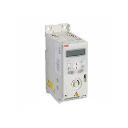
This Altivar 320 variable speed drive can feed 3-phase synchronous and asynchronous motors. Its book form factor allows for a simple and compact installation in your automation cabinets. It works at a rated power up to 2.2kW / 3hp and a rated voltage from 380V to 500V AC. Its robust design with IEC 60721-3-3 class 3C3 coated printed circuit boards allows to extend machine availability in harsh environmental conditions, for example at ambient temperatures of up to 60°C without the need of additional cooling. It incorporates functions suitable for the most common applications, including torque and speed accuracy at very low speed, high dynamic performance with flux vector control without sensor and extended frequency range for high-speed motors. It also incorporates parallel connection of motors and special drives using the voltage/frequency ratio and static speed accuracy and energy saving for open-loop synchronous motors. The drive software includes 5 safety functions that help machines meet safety requirements, whether or not they are used in conjunction with a Preventa safety module. These safety functions are configured using SoMove software. Altivar Machine ATV320 was designed for Original Equipment Manufacturers (OEMs) that meets simple and advanced application requirements covered for packaging, material handling, textile, material working, mechanical actuators and hoisting. It conforms to international standards IEC/EN 61800-5-1 and IEC/EN 61800-3 (immunity and conducted and radiated EMC emissions). It is also CE, UL, CSA, NOM, EAC and RCM certified. Mounting accessories and external options (braking resistors, line chokes, motor chokes, additional EMC filters) are available with Altivar Machine ATV320 drives. The type of external accessories and options depends on the drive rating. It is designed to be mounted in vertical position (+/- 10 °) on a panel, thanks to 4 fixing holes. It is fully integrated inside Schneider Electricâs EcoStruxure Machine through DTM. It is possible to configure, control, and diagnose ATV320 drives directly in SoMachine and SoMove software by means of the same software brick (DTM).
Main
| Characteristic | Value(s) |
|---|---|
| Range of Product | Altivar Machine ATV320 |
| Product or Component Type | Variable speed drive |
| Product Specific Application | Complex machines |
| Variant | Standard version |
| Format of the drive | Book |
| Mounting Mode | Cabinet mount |
| Communication Port Protocol | Modbus serial CANopen |
| Option card | communication module, CANopen communication module, EtherCAT communication module, Profibus DP V1 communication module, PROFINET communication module, Ethernet Powerlink communication module, EtherNet/IP communication module, DeviceNet |
| [Us] rated supply voltage | 380...500 V - 15...10 % |
| nominal output current | 5.5 A |
| Motor power kW | 2.2 kW heavy duty |
| EMC filter | Class C2 EMC filter integrated |
| IP degree of protection | IP20 |
Complementary
| Characteristic | Value(s) |
|---|---|
| Discrete input number | 7 |
| Discrete input type | STO safe torque off, 24 V DC1.5 kOhm DI1...DI6 logic inputs, 24 V DC 30 V) DI5 programmable as pulse input 0â¦30 kHz, 24 V DC 30 V) |
| Discrete input logic | Positive logic (source) Negative logic (sink) |
| Discrete output number | 3 |
| Discrete output type | Open collector DQ+ 0â¦1 kHz 30 V DC 100 mA Open collector DQ- 0â¦1 kHz 30 V DC 100 mA |
| Analogue input number | 3 |
| Analogue input type | AI1 voltage 0...10 V DC 30 kOhm 10 bits AI2 bipolar differential voltage +/- 10 V DC 30 kOhm 10 bits AI3 current 0...20 mA (or 4-20 mA, x-20 mA, 20-x mA or other patterns by configuration) 250 Ohm 10 bits |
| Analogue output number | 1 |
| Analogue output type | Software-configurable current AQ1 0...20 mA 800 Ohm 10 bits Software-configurable voltage AQ1 0...10 V DC 470 Ohm 10 bits |
| Relay output type | Configurable relay logic R1A 1 NO 100000 cycles Configurable relay logic R1B 1 NC 100000 cycles Configurable relay logic R1C Configurable relay logic R2A 1 NO 100000 cycles Configurable relay logic R2C |
| Maximum switching current | Relay output R1A, R1B, R1C resistive, cos phi = 1 3 A 250 V AC Relay output R1A, R1B, R1C resistive, cos phi = 1 3 A 30 V DC Relay output R1A, R1B, R1C, R2A, R2C inductive, cos phi = 0.4 7 ms 2 A 250 V AC Relay output R1A, R1B, R1C, R2A, R2C inductive, cos phi = 0.4 7 ms 2 A 30 V DC Relay output R2A, R2C resistive, cos phi = 1 5 A 250 V AC Relay output R2A, R2C resistive, cos phi = 1 5 A 30 V DC |
| Minimum switching current | Relay output R1A, R1B, R1C, R2A, R2C 5 mA 24 V DC |
| Method of access | Slave CANopen |
| 4 quadrant operation possible | True |
| Asynchronous motor control profile | Voltage/frequency ratio, 5 points Flux vector control without sensor, standard Voltage/frequency ratio - Energy Saving, quadratic U/f Flux vector control without sensor - Energy Saving Voltage/frequency ratio, 2 points |
| Synchronous motor control profile | Vector control without sensor |
| Maximum output frequency | 0.599 kHz |
| Acceleration and deceleration ramps | Linear U S CUS Ramp switching Acceleration/deceleration ramp adaptation Acceleration/deceleration automatic stop with DC injection |
| Motor slip compensation | Automatic whatever the load Adjustable 0...300 % Not available in voltage/frequency ratio (2 or 5 points) |
| Switching frequency | 2...16 kHz adjustable 4...16 kHz with derating factor |
| Nominal switching frequency | 4 kHz |
| Braking to standstill | By DC injection |
| Brake chopper integrated | True |
| Line current | 8.7 A 380 V heavy duty) 6.6 A 500 V heavy duty) |
| Maximum Input Current per Phase | 8.7 A |
| Maximum output voltage | 500 V |
| Apparent power | 5.7 kVA 500 V heavy duty) |
| Network Frequency | 50-60 Hz |
| Relative symmetric network frequency tolerance | 5 % |
| Prospective line Isc | 5 kA |
| Base load current at high overload | 4.8 A |
| Power dissipation in W | Fan 74.0 W 380 V 4 kHz |
| With safety function Safely Limited Speed (SLS) | True |
| With safety function Safe brake management (SBC/SBT) | False |
| With safety function Safe Operating Stop (SOS) | False |
| With safety function Safe Position (SP) | False |
| With safety function Safe programmable logic | False |
| With safety function Safe Speed Monitor (SSM) | False |
| With safety function Safe Stop 1 (SS1) | True |
| With sft fct Safe Stop 2 (SS2) | False |
| With safety function Safe torque off (STO) | True |
| With safety function Safely Limited Position (SLP) | False |
| With safety function Safe Direction (SDI) | False |
| Protection type | Input phase breaks drive Overcurrent between output phases and earth drive Overheating protection drive Short-circuit between motor phases drive Thermal protection drive |
| Width | 2.4 in (60 mm) |
| Height | 12.8 in (325.0 mm) |
| Depth | 9.6 in (245.0 mm) |
| Product Weight | 6.6 lb(US) (3.0 kg) |
| Transient overtorque | 170â¦200 % of nominal motor torque |
This Altivar 320 variable speed drive can feed 3-phase synchronous and asynchronous motors. Its book form factor allows for a simple and compact installation in your automation cabinets. It works at a rated power up to 4kW / 5hp and a rated voltage from 380V to 500V AC. Its robust design with IEC 60721-3-3 class 3C3 coated printed circuit boards allows to extend machine availability in harsh environmental conditions, for example at ambient temperatures of up to 60°C without the need of additional cooling. It incorporates functions suitable for the most common applications, including torque and speed accuracy at very low speed, high dynamic performance with flux vector control without sensor and extended frequency range for high-speed motors. It also incorporates parallel connection of motors and special drives using the voltage/frequency ratio and static speed accuracy and energy saving for open-loop synchronous motors. The drive software includes 5 safety functions that help machines meet safety requirements, whether or not they are used in conjunction with a Preventa safety module. These safety functions are configured using SoMove software. Altivar Machine ATV320 was designed for Original Equipment Manufacturers (OEMs) that meets simple and advanced application requirements covered for packaging, material handling, textile, material working, mechanical actuators and hoisting. It conforms to international standards IEC/EN 61800-5-1 and IEC/EN 61800-3 (immunity and conducted and radiated EMC emissions). It is also CE, UL, CSA, NOM, EAC and RCM certified. Mounting accessories and external options (braking resistors, line chokes, motor chokes, additional EMC filters) are available with Altivar Machine ATV320 drives. The type of external accessories and options depends on the drive rating. It is designed to be mounted in vertical position (+/- 10 °) on a panel, thanks to 4 fixing holes. It is fully integrated inside Schneider Electricâs EcoStruxure Machine through DTM. It is possible to configure, control, and diagnose ATV320 drives directly in SoMachine and SoMove software by means of the same software brick (DTM).
Main
| Characteristic | Value(s) |
|---|---|
| Range of Product | Altivar Machine ATV320 |
| Product or Component Type | Variable speed drive |
| Product Specific Application | Complex machines |
| Variant | Standard version |
| Format of the drive | Book |
| Mounting Mode | Cabinet mount |
| Communication Port Protocol | Modbus serial CANopen |
| Option card | communication module, CANopen communication module, EtherCAT communication module, Profibus DP V1 communication module, PROFINET communication module, Ethernet Powerlink communication module, EtherNet/IP communication module, DeviceNet |
| [Us] rated supply voltage | 380...500 V - 15...10 % |
| nominal output current | 9.5 A |
| Motor power kW | 4.0 kW heavy duty |
| EMC filter | Class C2 EMC filter integrated |
| IP degree of protection | IP20 |
Complementary
| Characteristic | Value(s) |
|---|---|
| Discrete input number | 7 |
| Discrete input type | STO safe torque off, 24 V DC1.5 kOhm DI1...DI6 logic inputs, 24 V DC 30 V) DI5 programmable as pulse input 0â¦30 kHz, 24 V DC 30 V) |
| Discrete input logic | Positive logic (source) Negative logic (sink) |
| Discrete output number | 3 |
| Discrete output type | Open collector DQ+ 0â¦1 kHz 30 V DC 100 mA Open collector DQ- 0â¦1 kHz 30 V DC 100 mA |
| Analogue input number | 3 |
| Analogue input type | AI1 voltage 0...10 V DC 30 kOhm 10 bits AI2 bipolar differential voltage +/- 10 V DC 30 kOhm 10 bits AI3 current 0...20 mA (or 4-20 mA, x-20 mA, 20-x mA or other patterns by configuration) 250 Ohm 10 bits |
| Analogue output number | 1 |
| Analogue output type | Software-configurable current AQ1 0...20 mA 800 Ohm 10 bits Software-configurable voltage AQ1 0...10 V DC 470 Ohm 10 bits |
| Relay output type | Configurable relay logic R1A 1 NO 100000 cycles Configurable relay logic R1B 1 NC 100000 cycles Configurable relay logic R1C Configurable relay logic R2A 1 NO 100000 cycles Configurable relay logic R2C |
| Maximum switching current | Relay output R1A, R1B, R1C resistive, cos phi = 1 3 A 250 V AC Relay output R1A, R1B, R1C resistive, cos phi = 1 3 A 30 V DC Relay output R1A, R1B, R1C, R2A, R2C inductive, cos phi = 0.4 7 ms 2 A 250 V AC Relay output R1A, R1B, R1C, R2A, R2C inductive, cos phi = 0.4 7 ms 2 A 30 V DC Relay output R2A, R2C resistive, cos phi = 1 5 A 250 V AC Relay output R2A, R2C resistive, cos phi = 1 5 A 30 V DC |
| Minimum switching current | Relay output R1A, R1B, R1C, R2A, R2C 5 mA 24 V DC |
| Method of access | Slave CANopen |
| 4 quadrant operation possible | True |
| Asynchronous motor control profile | Voltage/frequency ratio, 5 points Flux vector control without sensor, standard Voltage/frequency ratio - Energy Saving, quadratic U/f Flux vector control without sensor - Energy Saving Voltage/frequency ratio, 2 points |
| Synchronous motor control profile | Vector control without sensor |
| Maximum output frequency | 0.599 kHz |
| Acceleration and deceleration ramps | Linear U S CUS Ramp switching Acceleration/deceleration ramp adaptation Acceleration/deceleration automatic stop with DC injection |
| Motor slip compensation | Automatic whatever the load Adjustable 0...300 % Not available in voltage/frequency ratio (2 or 5 points) |
| Switching frequency | 2...16 kHz adjustable 4...16 kHz with derating factor |
| Nominal switching frequency | 4 kHz |
| Braking to standstill | By DC injection |
| Brake chopper integrated | True |
| Line current | 13.7 A 380 V heavy duty) 10.5 A 500 V heavy duty) |
| Maximum Input Current per Phase | 13.7 A |
| Maximum output voltage | 500 V |
| Apparent power | 9.1 kVA 500 V heavy duty) |
| Network Frequency | 50-60 Hz |
| Relative symmetric network frequency tolerance | 5 % |
| Prospective line Isc | 5 kA |
| Base load current at high overload | 9.5 A |
| Power dissipation in W | Fan 111 W 380 V 4 kHz |
| With safety function Safely Limited Speed (SLS) | True |
| With safety function Safe brake management (SBC/SBT) | False |
| With safety function Safe Operating Stop (SOS) | False |
| With safety function Safe Position (SP) | False |
| With safety function Safe programmable logic | False |
| With safety function Safe Speed Monitor (SSM) | False |
| With safety function Safe Stop 1 (SS1) | True |
| With sft fct Safe Stop 2 (SS2) | False |
| With safety function Safe torque off (STO) | True |
| With safety function Safely Limited Position (SLP) | False |
| With safety function Safe Direction (SDI) | False |
| Protection type | Input phase breaks drive Overcurrent between output phases and earth drive Overheating protection drive Short-circuit between motor phases drive Thermal protection drive |
| Width | 2.4 in (60 mm) |
| Height | 12.8 in (325.0 mm) |
| Depth | 9.6 in (245.0 mm) |
| Product Weight | 6.6 lb(US) (3.0 kg) |
| Transient overtorque | 170â¦200 % of nominal motor torque |

| Product | |
| Article Number (Market Facing Number) | 6ES72411CH301XB0 | 6ES72411CH301XB0 |
| Product Description | SIMATIC S7-1200, Communication Board CB 1241, RS485, terminal block, supports Freeport |
| Product family | CB 1241 RS485 communication board |
| Product Lifecycle (PLM) | PM300:Active Product |
| Additional Product Information | |
| EAN | 6940408100930 |
| UPC | 040892696707 |
| Commodity Code | 85176200 |
| LKZ_FDB/ CatalogID | ST72 |
| Product Group | 4510 |
| Group Code | R132 |
| Country of origin | China |
| SCIP number | Not available |
| Delivery information | |
| Net Weight (lb) | 0.068 lb |
| Package size unit of measure | Inch |
| Packaging Quantity | 1 |

| Product | |
| Article Number (Market Facing Number) | 6ES72151BG400XB0 | 6ES72151BG400XB0 |
| Product Description | SIMATIC S7-1200, CPU 1215C, COMPACT CPU, AC/DC/RELAY, 2 PROFINET PORT, ONBOARD I/O: 14 DI 24V DC; 10 DO RELAY 2A, 2 AI 0-10V DC, 2 AO 0-20MA DC, POWER SUPPLY: AC 85 - 264 V AC AT 47 - 63 HZ, PROGRAM/DATA MEMORY: 125 KB NOTE: !!V13 SP1 PORTAL SOFTWARE IS REQUIRED TO PROGRAM!! |
| Product family | CPU 1215C |
| Product Lifecycle (PLM) | PM300:Active Product |
| Additional Product Information | |
| EAN | 4047623402770 |
| UPC | 887621769079 |
| Commodity Code | 85371091 |
| LKZ_FDB/ CatalogID | ST72 |
| Product Group | 4509 |
| Group Code | R132 |
| Country of origin | Germany |
| SCIP number | Not available |
| Delivery information | |
| Net Weight (lb) | 1.107 lb |
| Package size unit of measure | Inch |
| Packaging Quantity | 1 |

| Product | |
| Article Number (Market Facing Number) | 6ES75121SK010AB0 | 6ES75121SK010AB0 |
| Product Description | *** spare part *** SIMATIC DP, CPU 1512SP F-1 PN for ET 200SP, central processing unit with work memory 300 KB for program and 1 MB for data, 1st interface: PROFINET IRT with 3-port switch, 48 ns bit performance, SIMATIC Memory Card required, BusAdapter required for port 1 and 2 |
| Product family | Not available |
| Product Lifecycle (PLM) | PM410:Product cancellation |
| Additional Product Information | |
| EAN | 4047623406037 |
| UPC | 804766166563 |
| Commodity Code | 85371091 |
| LKZ_FDB/ CatalogID | ST76 |
| Product Group | 4A7E |
| Group Code | R152 |
| Country of origin | Germany |
| SCIP number | Not available |
| Delivery information | |
| Net Weight (lb) | 0.862 lb |
| Package size unit of measure | Inch |
| Packaging Quantity | 1 |

I/O Unit, digital input module, 64-point, Fujitsu connection, 4.1 mA at 24/DC
| Product | |
| Article Number (Market Facing Number) | 6ES75050KA000AB0 | 6ES75050KA000AB0 |
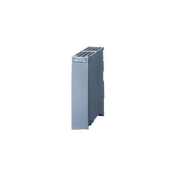
| Product Description | SIMATIC S7-1500, System power supply PS 25W 24 V DC, supplies the backplane bus of the S7-1500 with operating voltage |
| Product family | System power supplies |
| Product Lifecycle (PLM) | PM300:Active Product |
| Additional Product Information | |
| EAN | 4025515079897 |
| UPC | 887621139629 |
| Commodity Code | 85044095 |
| LKZ_FDB/ CatalogID | ST73 |
| Product Group | 4500 |
| Group Code | R132 |
| Country of origin | Germany |
| SCIP number | Not available |
| Delivery information | |
| Net Weight (lb) | 0.785 lb |
| Package size unit of measure | Inch |
| Packaging Quantity | 1 |
| Product | |
| Article Number (Market Facing Number) | 6ES72211BH320XB0 | 6ES72211BH320XB0 |
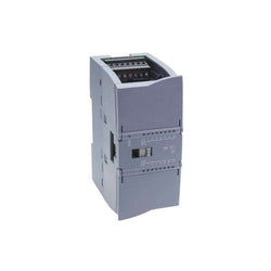
| Product Description | SIMATIC S7-1200, Digital input SM 1221, 16 DI, 24 V DC, Sink/Source |
| Product family | SM 1221 digital input modules |
| Product Lifecycle (PLM) | PM300:Active Product |
| Additional Product Information | |
| EAN | 6940408101920 |
| UPC | 887621217686 |
| Commodity Code | 85389091 |
| LKZ_FDB/ CatalogID | ST72 |
| Product Group | 4508 |
| Group Code | R132 |
| Country of origin | Germany |
| SCIP number | Not available |
| Delivery information | |
| Net Weight (lb) | 0.419 lb |
| Package size unit of measure | Inch |
| Packaging Quantity | 1 |

High-speed counter unit, 2 axes, 500 kHz, RS422 line driver or open collector input

Main
| Characteristic | Value(s) |
|---|---|
| Range of Product | Altivar Process ATV600 |
| Product Specific Application | Process and utilities |
| Product or Component Type | Variable speed drive |
| Variant | Standard version |
| Device short name | ATV630 |
| Mounting Mode | Cabinet mount |
| Communication Port Protocol | Ethernet Modbus serial Modbus TCP |
| [Us] rated supply voltage | 380...480 V - 15...10 % |
| [Us] rated supply voltage | 380...480 V |
| Relative symmetric mains voltage tolerance | 10 % |
| Relative symmetric network frequency tolerance | 5 % |
| nominal output current | 31.7 A |
| IP degree of protection | IP21 |
| Product destination | Asynchronous motors Synchronous motors |
| EMC filter | Integrated 32.8 ft (10 m) IEC 61800-3 category C2 Integrated 164.04 ft (50 m) IEC 61800-3 category C3 With EMC plate option |
| IP degree of protection | IP20IEC 61800-5-1 IP20IEC 60529 |
| type of cooling | Forced convection |
| Supply frequency | 50...60 Hz - 5...5 % |
| Motor power kW | 15 kW normal duty) 11 kW heavy duty) |
| Maximum Horse Power Rating | 20 hp normal duty 15 hp heavy duty |
| Line current | 27 A 380 V normal duty) 23.3 A 480 V normal duty) 20.6 A 380 V heavy duty) 18.1 A 480 V heavy duty) |
| Continuous output current | 31.7 A 4 kHz normal duty 23.5 A 4 kHz heavy duty |
| Speed drive output frequency | 0.1â¦500 Hz |
| Safety function | STO (safe torque off) SIL 3 |
| Option card | Slot A communication module, Profibus DP V1 Slot A communication module, PROFINET Slot A communication module, DeviceNet Slot A communication module, Modbus TCP/EtherNet/IP Slot A communication module, CANopen daisy chain RJ45 Slot A communication module, CANopen SUB-D 9 Slot A communication module, CANopen screw terminals Slot A/slot B digital and analog I/O extension module Slot A/slot B output relay extension module Slot A communication module, Ethernet IP/Modbus TCP/MD-Link communication module, BACnet MS/TP communication module, Ethernet Powerlink |
Complementary
| Characteristic | Value(s) |
|---|---|
| Discrete input number | 8 |
| Discrete input type | DI7, DI8 programmable as pulse input 0â¦30 kHz, 24 V DC <= 30 V) |
| Discrete input logic | 16 preset speeds |
| Discrete output number | 0 |
| Discrete output type | Relay outputs R1A, R1B, R1C 250 V AC 3000 mA Relay outputs R1A, R1B, R1C 30 V DC 3000 mA Relay outputs R2A, R2C 250 V AC 5000 mA Relay outputs R2A, R2C 30 V DC 5000 mA Relay outputs R3A, R3C 250 V AC 5000 mA Relay outputs R3A, R3C 30 V DC 5000 mA |
| Analogue input number | 3 |
| Analogue input type | AI1, AI2, AI3 software-configurable voltage 0...10 V DC 31.5 kOhm 12 bits AI1, AI2, AI3 software-configurable current 0...20 mA 250 Ohm 12 bits AI2 voltage analog input - 10...10 V DC 31.5 kOhm 12 bits |
| Analogue output number | 2 |
| Analogue output type | Software-configurable voltage AQ1, AQ2 0...10 V DC 470 Ohm 10 bits Software-configurable current AQ1, AQ2 0...20 mA 10 bits Software-configurable current DQ-, DQ+ 30 V DC Software-configurable current DQ-, DQ+ 100 mA |
| Relay output number | 3 |
| Relay output type | Configurable relay logic R1 fault relay NO/NC 100000 cycles Configurable relay logic R2 sequence relay NO 100000 cycles Configurable relay logic R3 sequence relay NO 100000 cycles |
| Maximum switching current | Relay output R1, R2, R3 resistive, cos phi = 1 3 A 250 V AC Relay output R1, R2, R3 resistive, cos phi = 1 3 A 30 V DC Relay output R1, R2, R3 inductive, cos phi = 0.4 7 ms 2 A 250 V AC Relay output R1, R2, R3 inductive, cos phi = 0.4 7 ms 2 A 30 V DC |
| Minimum switching current | Relay output R1, R2, R3 5 mA 24 V DC |
| Phase | 3 phase |
| Physical interface | Ethernet 2-wire RS 485 |
| Method of access | Slave Modbus TCP |
| Transmission Rate | 10, 100 Mbits 4800 bps, 9600 bps, 19200 bps, 38.4 Kbps |
| Transmission frame | RTU |
| Output voltage | <= power supply voltage |
| Permissible temporary current boost | 1.1 x In 60 s normal duty) 1.5 x In 60 s heavy duty) |
| Data format | 8 bits, configurable odd, even or no parity |
| Type of polarization | No impedance |
| Frequency resolution | Display unit 0.1 Hz Analog input 0.012/50 Hz |
| Electrical connection | Control removable screw terminals 0.5...1.5 mm² AWG 20...AWG 16 Line side screw terminal 10...16 mm² AWG 8...AWG 6 Motor screw terminal 10...16 mm² AWG 8...AWG 6 |
| Connector type | RJ45 on the remote graphic terminal)Ethernet/Modbus TCP RJ45 on the remote graphic terminal)Modbus serial |
| Exchange mode | Half duplex, full duplex, autonegotiation Ethernet/Modbus TCP |
| Number of addresses | 1â¦247 Modbus serial |
| Supply | External supply for digital inputs 24 V DC 19â¦30 V), <1.25 mA overload and short-circuit protection Internal supply for reference potentiometer (1 to 10 kOhm) 10.5 V DC +/- 5 %, <10 mA overload and short-circuit protection Internal supply for digital inputs and STO 24 V DC 21â¦27 V), <200 mA overload and short-circuit protection |
| Local signalling | 3 LEDs for local diagnostic 3 LEDs (dual colour) for embedded communication status 4 LEDs (dual colour) for communication module status 1 LED (red) for presence of voltage |
| Input compatibility | DI1...DI6 discrete input level 1 PLC IEC 61131-2 DI5, DI6 discrete input level 1 PLC IEC 65A-68 STOA, STOB discrete input level 1 PLC IEC 61131-2 |
| Discrete input logic | Positive logic (source) DI1...DI8), < 5 V, > 11 V Negative logic (sink) DI1...DI8), > 16 V, < 10 V |
| Sampling duration | 2 ms +/- 0.5 ms DI1...DI4) - discrete input 5 ms +/- 1 ms DI5, DI6) - discrete input 5 ms +/- 0.1 ms AI1, AI2, AI3) - analog input 10 ms +/- 1 ms AO1) - analog output |
| Accuracy | +/- 0.6 % AI1, AI2, AI3 for a temperature variation 60 °C analog input +/- 1 % AO1, AO2 for a temperature variation 60 °C analog output |
| Linearity error | AI1, AI2, AI3 +/- 0.15 % of maximum value analog input AO1, AO2 +/- 0.2 % analog output |
| Refresh time | Relay output R1, R2, R3)5 ms +/- 0.5 ms) |
| Isolation | Between power and control terminals |
| Variable speed drive application selection | Building - HVAC compressor centrifugal Food and beverage processing other application Mining mineral and metal fan Mining mineral and metal pump Oil and gas fan Water and waste water other application Building - HVAC screw compressor Food and beverage processing pump Food and beverage processing fan Food and beverage processing atomization Oil and gas electro submersible pump (ESP) Oil and gas water injection pump Oil and gas jet fuel pump Oil and gas compressor for refinery Water and waste water centrifuge pump Water and waste water positive displacement pump Water and waste water electro submersible pump (ESP) Water and waste water screw pump Water and waste water lobe compressor Water and waste water screw compressor Water and waste water compressor centrifugal Water and waste water fan Water and waste water conveyor Water and waste water mixer |
| Motor power range AC-3 | 15â¦25 kW 380â¦440 V 3 phase 15â¦25 kW 480â¦500 V 3 phase |
| Enclosure mounting | With heat sink |
| 4 quadrant operation possible | False |
| Asynchronous motor control profile | Constant torque standard Variable torque standard Optimized torque mode |
| Synchronous motor control profile | Permanent magnet motor Synchronous reluctance motor |
| Maximum output frequency | 500 kHz |
| Acceleration and deceleration ramps | Linear adjustable separately from 0.01...9999 s |
| Motor slip compensation | Can be suppressed Adjustable Automatic whatever the load Not available in permanent magnet motor law |
| Switching frequency | 2...12 kHz adjustable 4...12 kHz with derating factor |
| Nominal switching frequency | 4 kHz |
| Braking to standstill | By DC injection |
| Brake chopper integrated | False |
| Maximum Input Current per Phase | 27.0 A |
| Maximum output voltage | 480.0 V |
| Apparent power | 19.4 kVA 480 V normal duty) 15 kVA 480 V heavy duty) |
| Maximum transient current | 34.9 A 60 s normal duty) 35.3 A 60 s heavy duty) |
| Network Frequency | 50-60 Hz |
| Prospective line Isc | 50 kA |
| Base load current at high overload | 23.5 A |
| Base load current at low overload | 31.7 A |
| Power dissipation in W | Natural convection 59 W 380 V 4 kHz Forced convection 366 W 380 V 4 kHz |
| With safety function Safely Limited Speed (SLS) | False |
| With safety function Safe brake management (SBC/SBT) | False |
| With safety function Safe Operating Stop (SOS) | False |
| With safety function Safe Position (SP) | False |
| With safety function Safe programmable logic | False |
| With safety function Safe Speed Monitor (SSM) | False |
| With safety function Safe Stop 1 (SS1) | False |
| With sft fct Safe Stop 2 (SS2) | False |
| With safety function Safe torque off (STO) | True |
| With safety function Safely Limited Position (SLP) | False |
| With safety function Safe Direction (SDI) | False |
| Protection type | Thermal protection motor Safe torque off motor Motor phase break motor Thermal protection drive Safe torque off drive Overheating drive Overcurrent between output phases and earth drive Overload of output voltage drive Short-circuit protection drive Motor phase break drive Overvoltages on the DC bus drive Line supply overvoltage drive Line supply undervoltage drive Line supply phase loss drive Overspeed drive Break on the control circuit drive |
| Quantity per Set | 1 |
| Width | 7.7 in (195 mm) |
| Height | 18.9 in (480 mm) |
| Depth | 8.9 in (225.5 mm) |
| Product Weight | 28.7 lb(US) (13 kg) |

Specifications
Model |
LR-TB2000C |
|||
Type |
Cable with connector M12 |
|||
Detectable distance |
60 to 2000 mm 2.36" to 78.74"*1 |
|||
Spot diameter |
Approx. ø4 mm ø0.16" |
|||
Light source |
Type |
Red laser (660 nm) |
||
Laser class |
Class 2 laser product |
|||
Mutual interference prevention function |
4 units (when using the interference prevention function) |
|||
Timer |
OFF/OFF delay/ON delay/One-shot |
|||
Response time |
1 ms/10 ms/25 ms/100 ms/1000 ms |
|||
I/O |
Control output |
NPN open collector/PNP open collector selectable |
||
Analog output |
- |
|||
Protection circuit |
Protection against reverse power connection, power supply surges, output overcurrent, reverse output connection, and output surge |
|||
Power voltage |
20 to 30 VDC, including 10% ripple (P-P), Class 2 or LPS |
|||
Current consumption |
45 mA or less (without load)*5 |
|||
Environmental resistance |
Enclosure rating |
IP65/IP67 (IEC60529) |
||
Ambient light |
Incandescent lamp/Sunlight: 10,0000 lux or less |
|||
Ambient temperature |
-20 to +55 °C -4 to 131 °F (No freezing) |
|||
Relative humidity |
35 to 85 % RH (No condensation) |
|||
Vibration resistance |
10 to 55 Hz, Double amplitude 1.5 mm 0.06", 2 hours in each of the X, Y, and Z directions |
|||
Shock resistance |
1,000 m/s2, 6 times in each of the X, Y, and Z directions |
|||
Material |
Case: Zinc die cast (Nickel chrome plating), |
|||
Accompanying items |
Instruction manual, |
|||
Weight |
Approx. 85 g |
|||
*1 The range for displayable distance is from 50 to 2200. | ||||

PLC Direct is not an authorized distributor. We offer a broad range of in-stock products with minimal lead time.

B2 SERVO DRIVE, 400W, 230V 1PH/3
Variable Frequency Drive, 400 – 480 VAC 3 Phase Input, 480 VAC 3 Phase Output, 27.9 Amps

Specifications
Model |
GC-1000 |
|||
Input/output points |
Safety inputs |
16 |
||
Safety outputs |
6 |
|||
Safety relay output |
- |
|||
AUX outputs |
4 |
|||
Test outputs | ||||
Maximum number of connectable expansion units |
10*1 |
|||
Maximum number of connectable remote I/O modules |
4 |
|||
GC-Link ports |
2 ports |
|||
Safety input specifications |
Input device |
Contact output device or PNP output device |
||
Input type |
Type3 |
|||
ON level (voltage/current) |
Min. 11 V/2 mA |
|||
OFF level (voltage/current) |
Max. 5 V/1.5 mA |
|||
Short-circuit current |
Si 0 to 3: Approx. 5 mA |
|||
Protection circuit |
Surge protection circuit, wrong wiring protection circuit |
|||
Maximum cable length |
Max. 100 m 328.1' |
|||
Safety output specifications |
Output type |
PNP transistor output (DC-13, Type 0.5, Protected outputs)*2 |
||
Maximum load current |
500 mA |
|||
Residual voltage (during ON) |
Max. 2.0 V |
|||
Leakage current (during OFF) |
Max. 0.5mA |
|||
Maximum capacitive load |
0.5 µF |
|||
Load wiring resistance |
Max. 2.5Ω |
|||
Protection circuit |
Overcurrent protection circuit, reverse connection protection circuit |
|||
Maximum cable length |
Max. 30 m 98.4' |
|||
Safety relay output specifications |
Output type |
- |
||
Rated load (resistance load) | ||||
Rated load (inductive load) | ||||
Relay output mechanical life | ||||
Maximum cable length | ||||
B10d | ||||
Test output specifications |
Output type |
PNP transistor output*3 |
||
Maximum load current |
100 mA |
|||
Protection circuit |
Overcurrent protection circuit, reverse connection protection circuit |
|||
Maximum cable length |
Max. 100 m 328.1'*4 |
|||
AUX output specifications |
Output type |
Transistor output (PNP/NPN selectable by wiring) |
||
Maximum load current |
PNP: 100 mA, NPN: 20 mA |
|||
Residual voltage (during ON) |
Max. 2.0 V |
|||
Leakage current (during OFF) |
Max. 0.5 mA |
|||
Protection circuit |
Overcurrent protection circuit, reverse connection protection circuit |
|||
Maximum cable length |
Max. 30 m 98.4' |
|||
Communication interface |
USB |
USB2.0 |
||
Ethernet |
100BASE-TX |
|||
Network functionality |
EtherNet/IP™ *5, PROFINET, Modbus/TCP, MC protocol, UDP |
|||
Others |
LCD display |
1.77-inch color LCD |
||
Display buttons |
4 points (3 operation keys + 1 BACK key) |
|||
Applicable standards |
EMC |
EMS: IEC 61131-2/-6, EN61131-2/-6 |
||
Safety |
IEC 61508, EN 61508 SIL3 |
|||
Dimensions |
60×95×90 mm 2.36"× 3.74"×3.54" (W×D×H) |
|||
Power supply |
Power voltage |
24 VDC (-30 to +20%) Class 2 |
||
Power consumption |
Max. 200 mA |
|||
Environmental resistance |
Ambient temperature |
−10 to +55 °C 14 to 131 °F (No freezing) |
||
Relative humidity |
5 to 85% (No condensation) |
|||
Storage temperature |
−25 to +70 °C -13 to 158 °F (No freezing) |
|||
Operating altitude |
Max. 2000 m 6561.7' |
|||
Overvoltage category |
II |
|||
Pollution degree |
2 |
|||
Vibration resistance |
Frequency: 5 to 9 Hz, Half amplitude: 3.5 mm 0.14" |
|||
Shock resistance |
Acceleration: 150 m/s2, Operating time: 11 ms, 3 times each in X, Y, Z directions |
|||
Material |
Polycarbonate |
|||
Weight |
Approx. 260 g |
|||
*1 The bus extension unit “GC-B30” is not included in this number, and only one set of “GC-B30” can be used per setup. | ||||
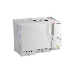
ACS550, 100HP, 3-Phase, 380-480V (Input), Nema 1 Enclosure, Variable Frequency Drives
Variable Frequency Drive, 400 – 480 VAC 3 Phase Input, 480 VAC 3 Phase Output, 4.1 Amps

PLC Direct is not an authorized distributor. We offer a broad range of in-stock products with minimal lead time.