
 1 year warranty


PLC Direct is not an authorized distributor. We offer a broad range of in-stock products with minimal lead time.

BRAND NEW CONDITION, GUARANTEED.

BRAND NEW CONDITION, GUARANTEED.

BRAND NEW CONDITION, GUARANTEED.
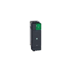
Variable Speed Drive - 30kW- 400V - 3 Phases - Altivar ATV340 Ethernet

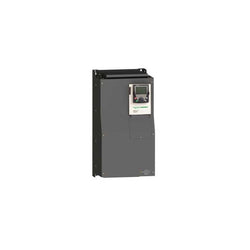
Variable Speed Drive Altivar 71 - 55kW-75hp - 480V - with EMC filter whitout Graphic Terminal
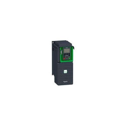
This Altivar Process ATV900 variable speed drive can feed 3-phase synchronous and asynchronous power motors. It is suitable for motors with power rating up to 11kW/15hp for applications requiring slight overload (up to 120%). It is suitable for motors with power rating up to 7.5kW/10hp for applications requiring significant overload (up to 150%). It works at a rated supply voltage from 380V to 480V AC. This variable speed / frequency drive (VSD / VFD) is specifically designed for industrial processes. In the following market segments, oil and gas, mining, minerals and metals, food and beverage water and wastewater. It offers high motor performance on any motor and total control of any kind of coupling in master/slave applications. Network services help ensure operation continuity even in case of connection breakdown. Web server and data logging help reduce downtime through fast troubleshooting and preventive maintenance. Its advanced connectivity, including EtherNet/IP and Modbus TCP, allows deep integration into automation architectures. It is designed to be mounted in vertical position (+/- 10 °) on a wall.
Main
| Characteristic | Value(s) |
|---|---|
| Range of Product | Altivar Process ATV900 |
| Product Specific Application | Process for industrial |
| Product or Component Type | Variable speed drive |
| Variant | Standard version With braking chopper |
| Device Application | Industrial Application |
| Product destination | Asynchronous motors Synchronous motors |
| Phase | 3 phase |
| Mounting Mode | Wall mount |
| Continuous output current | 23.5 A 4 kHz normal duty 16.5 A 4 kHz heavy duty |
| Communication Port Protocol | EtherNet/IP Modbus serial Modbus TCP |
| Option card | Slot A communication module Profibus DP V1 Slot A communication module PROFINET Slot A communication module DeviceNet Slot A communication module EtherCAT Slot A communication module CANopen daisy chain RJ45 Slot A communication module CANopen SUB-D 9 Slot A communication module CANopen screw terminals Slot A/slot B/slot C digital and analog I/O extension module Slot A/slot B/slot C output relay extension module Slot B 5/12 V digital encoder interface module Slot B analog encoder interface module Slot B resolver encoder interface module communication module Ethernet Powerlink |
| [Us] rated supply voltage | 380...480 V - 15...10 % |
| [Us] rated supply voltage | 380...480 V |
| Relative symmetric mains voltage tolerance | 10 % |
| Relative symmetric network frequency tolerance | 5 % |
| nominal output current | 23.5 A |
| Motor power kW | 11.0 kW normal duty 7.5 kW heavy duty |
| EMC filter | Integrated With EMC plate option |
| IP degree of protection | IP21 |
| Degree of protection | UL type 1 |
Complementary
| Characteristic | Value(s) |
|---|---|
| Electrical connection | Control screw terminal 0.5...1.5 mm² AWG 20...AWG 16 Motor screw terminal 6...10 mm² AWG 10...AWG 8 Line side screw terminal 6 mm² AWG 10 DC bus screw terminal 6 mm² AWG 10 |
| Transmission Rate | 10/100 Mbit/s Ethernet IP/Modbus TCP 4.8, 9.6, 19.2, 38.4 kbit/s Modbus serial |
| Exchange mode | Half duplex, full duplex, autonegotiation Ethernet IP/Modbus TCP |
| Data format | 8 bits, configurable odd, even or no parity Modbus serial |
| Type of polarization | No impedance Modbus serial |
| Number of addresses | 1â¦247 Modbus serial |
| Supply | External supply for digital inputs 24 V DC 19â¦30 V), <1.25 mA overload and short-circuit protection Internal supply for reference potentiometer (1 to 10 kOhm) 10.5 V DC +/- 5 %, <10 mA overload and short-circuit protection Internal supply for digital inputs and STO 24 V DC 21â¦27 V), <200 mA overload and short-circuit protection |
| Local signalling | Local diagnostic: 3 LED (mono/dual colour) Embedded communication status: 5 LED (dual colour) Communication module status: 2 LED (dual colour) Presence of voltage: 1 LED (red) |
| Input compatibility | DI1...DI8 discrete input level 1 PLC IEC 61131-2 DI7, DI8 pulse input level 1 PLC IEC 65A-68 STOA, STOB discrete input level 1 PLC IEC 61131-2 |
| Discrete input logic | Positive logic (source) DI1...DI8), < 5 V, > 11 V Negative logic (sink) DI1...DI8), > 16 V, < 10 V Positive logic (source) DI7, DI8), < 0.6 V, > 2.5 V Positive logic (source) STOA, STOB), < 5 V, > 11 V |
| Sampling duration | 2 ms +/- 0.5 ms DI1...DI8) - discrete input 5 ms +/- 1 ms DI7, DI8) - pulse input 1 ms +/- 1 ms AI1, AI2, AI3) - analog input 5 ms +/- 1 ms AQ1, AQ2) - analog output |
| Accuracy | +/- 0.6 % AI1, AI2, AI3 for a temperature variation 60 °C analog input +/- 1 % AQ1, AQ2 for a temperature variation 60 °C analog output |
| Linearity error | AI1, AI2, AI3 +/- 0.15 % of maximum value analog input AQ1, AQ2 +/- 0.2 % analog output |
| Refresh time | Relay output R1, R2, R3)5 ms +/- 0.5 ms) |
| Isolation | Between power and control terminals |
| Discrete input number | 10 |
| Discrete input type | DI1...DI8 programmable, 24 V DC <= 30 V)3.5 kOhm DI7, DI8 programmable as pulse input 0â¦30 kHz, 24 V DC <= 30 V) STOA, STOB safe torque off, 24 V DC <= 30 V)> 2.2 kOhm |
| Discrete input logic | 16 preset speeds |
| Discrete output number | 2 |
| Discrete output type | Logic output DQ+ 0â¦1 kHz <= 30 V DC 100 mA Programmable as pulse output DQ+ 0â¦30 kHz <= 30 V DC 20 mA Logic output DQ- 0â¦1 kHz <= 30 V DC 100 mA |
| Analogue input number | 3 |
| Analogue input type | AI1, AI2, AI3 software-configurable voltage 0...10 V DC 30 kOhm 12 bits AI1, AI2, AI3 software-configurable current 0...20 mA/4...20 mA 250 Ohm 12 bits |
| Analogue output number | 2 |
| Analogue output type | Software-configurable voltage AQ1, AQ2 0...10 V DC 470 Ohm 10 bits Software-configurable current AQ1, AQ2 0...20 mA 500 Ohm 10 bits |
| Relay output number | 3 |
| Relay output type | Configurable relay logic R1 fault relay NO/NC 100000 cycles Configurable relay logic R2 sequence relay NO 1000000 cycles Configurable relay logic R3 sequence relay NO 1000000 cycles |
| Maximum switching current | Relay output R1 resistive, cos phi = 1 3 A 250 V AC Relay output R1 resistive, cos phi = 1 3 A 30 V DC Relay output R1 inductive, cos phi = 0.4 7 ms 2 A 250 V AC Relay output R1 inductive, cos phi = 0.4 7 ms 2 A 30 V DC Relay output R2, R3 resistive, cos phi = 1 5 A 250 V AC Relay output R2, R3 resistive, cos phi = 1 5 A 30 V DC Relay output R2, R3 inductive, cos phi = 0.4 7 ms 2 A 250 V AC Relay output R2, R3 inductive, cos phi = 0.4 7 ms 2 A 30 V DC |
| Minimum switching current | Relay output R1, R2, R3 5 mA 24 V DC |
| Physical interface | Ethernet 2-wire RS 485 |
| Connector Type | 2 RJ45 1 RJ45 |
| Method of access | Slave Modbus TCP |
| Transmission Rate | 10, 100 Mbits 4.8 kbps 9600 bit/s 19200 bit/s |
| Transmission frame | RTU |
| Number of addresses | 1â¦247 |
| Data format | 8 bits, configurable odd, even or no parity |
| Type of polarization | No impedance |
| 4 quadrant operation possible | True |
| Asynchronous motor control profile | Variable torque standard Optimized torque mode Constant torque standard |
| Synchronous motor control profile | Permanent magnet motor Synchronous reluctance motor |
| Maximum output frequency | 599 Hz |
| Acceleration and deceleration ramps | Linear adjustable separately from 0.01...9999 s |
| Motor slip compensation | Adjustable Automatic whatever the load Can be suppressed Not available in permanent magnet motor law |
| Switching frequency | 2...16 kHz adjustable 4...16 kHz with derating factor |
| Nominal switching frequency | 4 kHz |
| Braking to standstill | By DC injection |
| Brake chopper integrated | True |
| Line current | 19.8 A 380 V normal duty) 14.1 A 380 V heavy duty) 17.0 A 480 V normal duty) 12.5 A 480 V heavy duty) |
| Maximum Input Current per Phase | 19.8 A |
| Maximum output voltage | 480.0 V |
| Apparent power | 14.1 kVA 480 V normal duty) 10.4 kVA 480 V heavy duty) |
| Maximum transient current | 28.2 A 60 s normal duty) 24.8 A 60 s heavy duty) |
| Network Frequency | 50-60 Hz |
| Prospective line Isc | 50 kA |
| Base load current at high overload | 16.5 A |
| Base load current at low overload | 23.5 A |
| Power dissipation in W | Natural convection 51 W 380 V 4 kHz Forced convection 255 W 380 V 4 kHz |
| With safety function Safely Limited Speed (SLS) | True |
| With safety function Safe brake management (SBC/SBT) | True |
| With safety function Safe Operating Stop (SOS) | False |
| With safety function Safe Position (SP) | False |
| With safety function Safe programmable logic | False |
| With safety function Safe Speed Monitor (SSM) | False |
| With safety function Safe Stop 1 (SS1) | True |
| With sft fct Safe Stop 2 (SS2) | False |
| With safety function Safe torque off (STO) | True |
| With safety function Safely Limited Position (SLP) | False |
| With safety function Safe Direction (SDI) | False |
| Protection type | Thermal protection motor Safe torque off motor Motor phase break motor Thermal protection drive Safe torque off drive Overheating drive Overcurrent between output phases and earth drive Overload of output voltage drive Short-circuit protection drive Motor phase break drive Overvoltages on the DC bus drive Line supply overvoltage drive Line supply undervoltage drive Line supply phase loss drive Overspeed drive Break on the control circuit drive |
| Quantity per Set | 1 |
| Width | 6.7 in (171 mm) |
| Height | 16.1 in (409 mm) |
| Depth | 9.3 in (236 mm) |
| Product Weight | 17.0 lb(US) (7.7 kg) |
Variable Speed Drive Altivar ATV12 - 0.18kW - 0.25hp - 200..240V - 1ph

Variable Speed Drive - ATV930 - 55kW - 400/480V - with braking unit - IP21

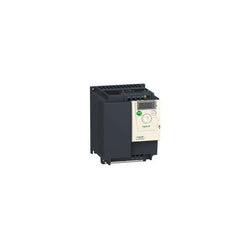
This Altivar 32 3-phase variable speed drive has a rated power of 11kW, and a supply voltage of 380V to 500V AC. It is designed for applications such as small conveyors, hoists, bagging / labeling machines, mixers, kneaders, textile machines, pumps, compressors, fans, wood-working and metal processing machines. It has a 180mm-wide compact form-factor, allowing for a flexible and easy installation on a mounting plate without any space between adjacent drives. It also offers a snap-lock seal, status and faults display, a jog dial navigation button and an integrated EMC filter. It offers high readability of key parameters thanks to a bright LED 4-digit display. SoMove software compatibility enables saving and transfering of configurations to spare drive, reducing maintenance downtime.
Main
| Characteristic | Value(s) |
|---|---|
| Range of Product | Altivar 32 |
| Product or Component Type | Variable speed drive |
| Product destination | Synchronous motors Asynchronous motors |
| Product Specific Application | Complex machines |
| Function Available | - |
| Assembly style | With heat sink |
| Component name | ATV32 |
| EMC filter | Class C2 EMC filter integrated |
| Phase | 3 phase |
| [Us] rated supply voltage | 380...500 V - 15...10 % |
| Supply voltage limits | 323â¦550 V |
| Supply frequency | 50...60 Hz - 5...5 % |
| Network Frequency | 47.5...63 Hz |
| Motor power kW | 11 kW 380...480 V |
| Maximum Horse Power Rating | 15 hp 380...480 V |
Complementary
| Characteristic | Value(s) |
|---|---|
| Line current | 25.6 A 500 V 3 phase 11 kW / 15 hp 36.6 A 380 V 3 phase 11 kW / 15 hp |
| Apparent power | 31.7 kVA 500 V 3 phase 15 kW / 20 hp |
| Prospective line Isc | 22 kA 3 phase |
| Nominal output current | 27.7 A 4 kHz 500 V 11 kW / 15 hp |
| Maximum transient current | 41.6 A 60 s 11 kW / 15 hp |
| Output frequency | 0.0005â¦0.599 kHz |
| Nominal switching frequency | 4 kHz |
| Switching frequency | 2...16 kHz adjustable |
| Speed range | 1â¦100 asynchronous motor in open-loop mode |
| Speed accuracy | +/- 10 % of nominal slip 0.2 Tn to Tn |
| Torque accuracy | +/- 15 % |
| Transient overtorque | 170â¦200 % |
| Braking torque | <= 170 % with braking resistor |
| Asynchronous motor control profile | Flux vector control without sensor, standard Voltage/frequency ratio, 5 points Voltage/frequency ratio, 2 points Voltage/frequency ratio - Energy Saving, quadratic U/f Flux vector control without sensor - Energy Saving, NoLoad law |
| Synchronous motor control profile | Vector control without sensor |
| Regulation loop | Adjustable PID regulator |
| Motor slip compensation | Adjustable 0...300 % Automatic whatever the load Not available in voltage/frequency ratio (2 or 5 points) |
| Local signalling | 1 LED red drive voltage 1 LED green CANopen run 1 LED red CANopen error 1 LED red drive fault |
| Output voltage | <= power supply voltage |
| Noise level | 43 dB 86/188/EEC |
| Insulation | Electrical between power and control |
| Electrical connection | Screw terminal 0.5...1.5 mm², AWG 18...AWG 14 control) Removable screw terminals 6...16 mm², AWG 8...AWG 6 motor/braking resistor) Screw terminal 10...16 mm², AWG 8...AWG 6 power supply) |
| Tightening torque | 4.4 lbf.in (0.5 N.m), 4.4 lb/ft control) 10.6 lbf.in (1.2 N.m), 10.6 lb/ft motor/braking resistor) 10.6 lbf.in (1.2 N.m), 10.6 lb/ft power supply) |
| Supply | Internal supply for reference potentiometer (1 to 10 kOhm) 10.5 V DC +/- 5 %, <10 mA overload and short-circuit protection |
| Analogue input number | 3 |
| Analogue input type | AI1 voltage 0...10 V DC 30000 Ohm 10 bits AI2 bipolar differential voltage +/- 10 V DC 30000 Ohm 10 bits AI3 current 0...20 mA (or 4-20 mA, x-20 mA, 20-x mA or other patterns by configuration) 250 Ohm 10 bits |
| Sampling duration | 2 ms AI1, AI2, AI3) - analog 2 ms AO1) - analog |
| Response time | LI1...LI6 8 ms +/- 0.7 ms logic R1A, R1B, R1C 2 ms relay R2A, R2C 2 ms relay |
| Accuracy | +/- 0.2 % AI1, AI2, AI3) for a temperature of -10...60 °C +/- 0.5 % AI1, AI2, AI3) for a temperature of 25 °C +/- 1 % AO1) for a temperature of 25 °C +/- 2 % AO1) for a temperature of -10...60 °C |
| Linearity error | +/- 0.2...0.5 % of maximum value AI1, AI2, AI3) +/- 0.3 % AO1) |
| Analogue output number | 1 |
| Analogue output type | AO1 software-configurable current 0...20 mA 800 Ohm 10 bits AO1 software-configurable voltage 0...10 V 470 Ohm 10 bits |
| Discrete output number | 3 |
| Discrete output type | Configurable relay logic R1A, R1B, R1C) NO/NC - 100000 cycles Configurable relay logic R2A, R2B) NO - 100000 cycles Logic LO) |
| Minimum switching current | 5 mA 24 V DC configurable relay logic |
| Maximum switching current | R1 3 A 250 V AC resistive, cos phi = 1 R1 4 A 30 V DC resistive, cos phi = 1 R1, R2 2 A 250 V AC inductive, cos phi = 0.4 R1, R2 2 A 30 V DC inductive, cos phi = 0.4 R2 5 A 250 V AC resistive, cos phi = 1 R2 5 A 30 V DC resistive, cos phi = 1 |
| Discrete input number | 7 |
| Discrete input type | Programmable (sink/source) LI1...LI4)24...30 V DC level 1 PLC Programmable as pulse input 20 kpps LI5)24...30 V DC level 1 PLC Switch-configurable PTC probe LI6)24...30 V DC Safe torque off STO)24...30 V DC - 1500 Ohm |
| Discrete input logic | Negative logic (sink) LI1...LI6), > 19 V, < 13 V Positive logic (source) LI1...LI6), < 5 V, > 11 V |
| Acceleration and deceleration ramps | CUS Deceleration ramp adaptation Linear Deceleration ramp automatic stop DC injection S Ramp switching U |
| Braking to standstill | By DC injection |
| Protection type | Input phase breaks drive Overcurrent between output phases and earth drive Overheating protection drive Short-circuit between motor phases drive Thermal protection drive |
| Communication Port Protocol | CANopen Modbus |
| Connector type | 1 RJ45 on front face)Modbus/CANopen |
| Physical interface | 2-wire RS 485 Modbus |
| Transmission frame | RTU Modbus |
| Type of polarization | No impedance Modbus |
| Number of addresses | 1â¦127 CANopen 1â¦247 Modbus |
| Method of access | Slave CANopen |
| Electromagnetic compatibility | 1.2/50 µs - 8/20 µs surge immunity test, level 3 IEC 61000-4-5 Conducted radio-frequency immunity test, level 3 IEC 61000-4-6 Electrical fast transient/burst immunity test, level 4 IEC 61000-4-4 Electrostatic discharge immunity test, level 3 IEC 61000-4-2 Radiated radio-frequency electromagnetic field immunity test, level 3 IEC 61000-4-3 Voltage dips and interruptions immunity test IEC 61000-4-11 |
| Width | 7.09 in (180 mm) |
| Height | 15.9 in (404 mm) |
| Depth | 9.1 in (232 mm) |
| Product Weight | 19.2 lb(US) (8.7 kg) |
| Option card | Communication card CANopen daisy chain Communication card CANopen open style Communication card DeviceNet Communication card EtherNet/IP Communication card Profibus DP V1 |
| Functionality | Mid |
| Specific application | Other applications |

BRAND NEW CONDITION, GUARANTEED.
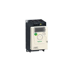
This Altivar 12 variable speed drive can feed 3-phase asynchronous motors in supply line connection. It works at a rated power up to 4kW / 5hp and a rated voltage from 200V to 240V AC. It is designed with heatsink for normal environments and fan-cooled enclosure. Transient overtorque function prevents stoppages by unjamming the machine with extra torque, when needed, this reduces downtime and maintenance costs. It features underload and overload detection, this contribute to protect your installation. The Altivar 12 drive integrates as standard the Modbus communication protocol, which can be accessed via the RJ45 connector located on the underside of the drive. It is designed for simple industry and commercial machines and appliances, such as conveyors, pumps, extractors, access barriers and treadmills. SoMove software compatibility enables saving and transfering of configurations to spare drive, reducing maintenance downtime. It features an optimized application of power and torque for ventilation and pumping applications, this allows up to 30% energy savings.
Main
| Characteristic | Value(s) |
|---|---|
| Range of Product | Altivar 12 |
| Product or Component Type | Variable speed drive |
| Product Specific Application | Simple machine |
| Mounting Mode | Cabinet mount |
| Communication Port Protocol | Modbus |
| Supply frequency | 50/60 Hz +/- 5 % |
| [Us] rated supply voltage | 200...240 V - 15...10 % |
| nominal output current | 16.7 A |
| Motor power kW | 4 kW |
| Maximum Horse Power Rating | 5 hp |
| EMC filter | Without EMC filter |
| IP degree of protection | IP20 |
| Maximum Horse Power Rating | 5 hp |
Complementary
| Characteristic | Value(s) |
|---|---|
| Discrete input number | 4 |
| Discrete output number | 2 |
| Analogue input number | 1 |
| Analogue output number | 1 |
| Relay output number | 1 |
| Physical interface | 2-wire RS 485 |
| Connector Type | 1 RJ45 |
| Continuous output current | 16.7 A 4 kHz |
| Method of access | Server Modbus serial |
| Speed drive output frequency | 0.5â¦400 Hz |
| Speed range | 1â¦20 |
| Sampling duration | 20 ms +/- 1 ms logic input 10 ms analogue input |
| Linearity error | +/- 0.3 % of maximum value analogue input |
| Frequency resolution | Analog input converter A/D, 10 bits Display unit 0.1 Hz |
| Time constant | 20 ms +/- 1 ms for reference change |
| Transmission Rate | 9.6 kbit/s 19.2 kbit/s 38.4 kbit/s |
| Transmission frame | RTU |
| Number of addresses | 1â¦247 |
| Data format | 8 bits, configurable odd, even or no parity |
| Communication service | Read holding registers (03) 29 words Write single register (06) 29 words Write multiple registers (16) 27 words Read/write multiple registers (23) 4/4 words Read device identification (43) |
| Type of polarization | No impedance |
| 4 quadrant operation possible | False |
| Asynchronous motor control profile | Quadratic voltage/frequency ratio Voltage/frequency ratio (V/f) Sensorless flux vector control |
| Maximum output frequency | 4 kHz |
| Transient overtorque | 150â¦170 % of nominal motor torque depending on drive rating and type of motor |
| Acceleration and deceleration ramps | S U Linear from 0 to 999.9 s |
| Motor slip compensation | Preset in factory Adjustable |
| Switching frequency | 2...16 kHz adjustable 4...16 kHz with derating factor |
| Nominal switching frequency | 4 kHz |
| Braking to standstill | By DC injection |
| Brake chopper integrated | False |
| Line current | 23.8 A 100 V heavy duty) 19.9 A 120 V heavy duty) |
| Maximum Input Current per Phase | 19.9 A |
| Maximum output voltage | 240 V |
| Apparent power | 8.3 kVA 240 V heavy duty) |
| Maximum transient current | 25.0 A 60 s heavy duty) 27.6 A 2 s heavy duty) |
| Network Frequency | 50-60 Hz |
| Relative symmetric network frequency tolerance | 5 % |
| Prospective line Isc | 5 kA |
| Base load current at high overload | 16.7 A |
| Power dissipation in W | Forced cooling 128.0 W |
| With safety function Safely Limited Speed (SLS) | False |
| With safety function Safe brake management (SBC/SBT) | False |
| With safety function Safe Operating Stop (SOS) | False |
| With safety function Safe Position (SP) | False |
| With safety function Safe programmable logic | False |
| With safety function Safe Speed Monitor (SSM) | False |
| With safety function Safe Stop 1 (SS1) | False |
| With sft fct Safe Stop 2 (SS2) | False |
| With safety function Safe torque off (STO) | False |
| With safety function Safely Limited Position (SLP) | False |
| With safety function Safe Direction (SDI) | False |
| Protection type | Line supply overvoltage Line supply undervoltage Overcurrent between output phases and earth Overheating protection Short-circuit between motor phases Against input phase loss in three-phase Thermal motor protection via the drive by continuous calculation of I²t |
| Tightening torque | 10.6 lbf.in (1.2 N.m) |
| Insulation | Electrical between power and control |
| Quantity per Set | Set of 1 |
| Width | 5.5 in (140 mm) |
| Height | 7.2 in (184 mm) |
| Depth | 5.6 in (141.2 mm) |
| Product Weight | 4.4 lb(US) (2 kg) |

PLC Direct is not an authorized distributor. We offer a broad range of in-stock products with minimal lead time.
Main
| Characteristic | Value(s) |
|---|---|
| Range of Product | Altivar 71 |
| Product or Component Type | Variable speed drive |
| Product Specific Application | Complex, high-power machines |
| Component name | ATV71 |
| Motor power kW | 90 kW, 3 phase 380...480 V |
| Maximum Horse Power Rating | 125 hp, 3 phase 380...480 V |
| Maximum motor cable length | 328.08 ft (100 m) shielded cable 656.2 ft (200 m) unshielded cable |
| power supply voltage | 380...480 V - 15...10 % |
| Phase | 3 phase |
| Line current | 134 A 480 V 3 phase 90 kW / 125 hp 166 A 380 V 3 phase 90 kW / 125 hp |
| EMC filter | Integrated |
| Assembly style | With heat sink |
| Variant | Reinforced version |
| Apparent power | 109.3 kVA 380 V 3 phase 90 kW / 125 hp |
| Prospective line Isc | 35 kA 3 phase |
| Nominal output current | 179 A 2.5 kHz 380 V 3 phase 90 kW / 125 hp 179 A 2.5 kHz 460 V 3 phase 90 kW / 125 hp |
| Maximum transient current | 269 A 60 s 3 phase 90 kW / 125 hp 295 A 2 s 3 phase 90 kW / 125 hp |
| Output frequency | 0.1â¦500 Hz |
| Nominal switching frequency | 2.5 kHz |
| Switching frequency | 2.5...8 kHz adjustable 2.5...8 kHz with derating factor |
| Asynchronous motor control profile | Voltage/frequency ratio (2 or 5 points) Sensorless flux vector control (SFVC) (voltage or current vector) Flux vector control (FVC) with sensor (current vector) ENA (Energy adaptation) system for unbalanced loads |
| Type of polarization | No impedance Modbus |
Complementary
| Characteristic | Value(s) |
|---|---|
| Product destination | Asynchronous motors Synchronous motors |
| power supply voltage limits | 323â¦528 V |
| power supply frequency | 50...60 Hz - 5...5 % |
| power supply frequency limits | 47.5...63 Hz |
| Speed range | 1â¦100 asynchronous motor in open-loop mode, without speed feedback 1â¦1000 asynchronous motor in closed-loop mode with encoder feedback 1â¦50 synchronous motor in open-loop mode, without speed feedback |
| Speed accuracy | +/- 0.01 % of nominal speed in closed-loop mode with encoder feedback 0.2 Tn to Tn +/- 10 % of nominal slip without speed feedback 0.2 Tn to Tn |
| Torque accuracy | +/- 15 % in open-loop mode, without speed feedback +/- 5 % in closed-loop mode with encoder feedback |
| Transient overtorque | 170 % +/- 10 % 60 s every 10 minutes 220 % +/- 10 % 2 s |
| Braking torque | <= 150 % with braking or hoist resistor 30 % without braking resistor |
| Synchronous motor control profile | Vector control without speed feedback |
| Regulation loop | Adjustable PI regulator |
| Motor slip compensation | Suppressable Not available in voltage/frequency ratio (2 or 5 points) Automatic whatever the load Adjustable |
| diagnostic | 1 LED (red) for drive voltage |
| Output voltage | <= power supply voltage |
| Insulation | Electrical between power and control |
| type of cable for mounting in an enclosure | With a NEMA Type1 kit 3 UL 508 cable 104 °F (40 °C), copper 75 °C / PVC With an IP21 or an IP31 kit 3 IEC cable 104 °F (40 °C), copper 70 °C / PVC Without mounting kit 1 IEC cable 113 °F (45 °C), copper 70 °C / PVC Without mounting kit 1 IEC cable 113 °F (45 °C), copper 90 °C / XLPE/EPR |
| Electrical connection | Terminal 2.5 mm², AWG 14 AI1-/AI1+, AI2, AO1, R1A, R1B, R1C, R2A, R2B, LI1...LI6, PWR) Terminal 2 x 100 mm² L1/R, L2/S, L3/T, U/T1, V/T2, W/T3) Terminal 60 mm² PA, PB) Terminal 2 x 100 mm² PC/-, PO, PA/+) |
| Tightening torque | 5.3 lbf.in (0.6 N.m) AI1-/AI1+, AI2, AO1, R1A, R1B, R1C, R2A, R2B, LI1...LI6, PWR) 212.4 lbf.in (24 N.m), 212 lb.in L1/R, L2/S, L3/T, U/T1, V/T2, W/T3) 106.2 lbf.in (12 N.m), 106 lb.in PA, PB) 362.9 lbf.in (41 N.m), 360 lb.in PC/-, PO, PA/+) |
| Supply | Internal supply for reference potentiometer (1 to 10 kOhm) 10.5 V DC +/- 5 %, <10 mA overload and short-circuit protection Internal supply 24 V DC 21â¦27 V), <200 mA overload and short-circuit protection |
| Analogue input number | 2 |
| Analogue input type | AI1-/Al1+ bipolar differential voltage +/- 10 V DC 24 V max 11 bits + sign AI2 software-configurable current 0...20 mA 242 Ohm 11 bits AI2 software-configurable voltage 0...10 V DC 24 V max 30000 Ohm 11 bits |
| input sampling time | 2 ms +/- 0.5 ms AI1-/Al1+) - analog 2 ms +/- 0.5 ms Al2) - analog 2 ms +/- 0.5 ms LI1...LI5) - discrete 2 ms +/- 0.5 ms LI6)if configured as logic input - discrete |
| Response time | <= 100 ms in STO (Safe Torque Off) AO1 2 ms +/- 0.5 ms analog R1A, R1B, R1C 7 ms +/- 0.5 ms discrete R2A, R2B 7 ms +/- 0.5 ms discrete |
| absolute accuracy precision | +/- 0.6 % AI1-/Al1+) for a temperature variation 60 °C +/- 0.6 % AI2) for a temperature variation 60 °C +/- 1 % AO1) for a temperature variation 60 °C |
| Linearity error | +/- 0.15 % of maximum value AI1-/Al1+, AI2) +/- 0.2 % AO1) |
| Analogue output number | 1 |
| Analogue output type | AO1 software-configurable logic output 10 V 20 mA AO1 software-configurable current 0...20 mA 500 Ohm 10 bits AO1 software-configurable voltage 0...10 V DC 470 Ohm 10 bits |
| Discrete output number | 2 |
| Discrete output type | Configurable relay logic R1A, R1B, R1C) NO/NC - 100000 cycles Configurable relay logic R2A, R2B) NO - 100000 cycles |
| Minimum switching current | 3 mA 24 V DC configurable relay logic |
| Maximum switching current | R1, R2 2 A 250 V AC inductive, cos phi = 0.4 R1, R2 2 A 30 V DC inductive, cos phi = 0.4 R1, R2 5 A 250 V AC resistive, cos phi = 1 R1, R2 5 A 30 V DC resistive, cos phi = 1 |
| Discrete input number | 7 |
| Discrete input type | LI1...LI5 programmable 24 V DC level 1 PLC 3500 Ohm LI6 switch-configurable 24 V DC level 1 PLC 3500 Ohm LI6 switch-configurable PTC probe 0â¦6 1500 Ohm PWR safety input 24 V DC 1500 Ohm ISO 13849-1 level d |
| Discrete input logic | Negative logic (sink) LI1...LI5), > 16 V, < 10 V Positive logic (source) LI1...LI5), < 5 V, > 11 V Negative logic (sink) LI6)if configured as logic input, > 16 V, < 10 V Positive logic (source) LI6)if configured as logic input, < 5 V, > 11 V |
| Acceleration and deceleration ramps | Automatic adaptation of ramp if braking capacity exceeded, by using resistor Linear adjustable separately from 0.01 to 9000 s S, U or customized |
| Braking to standstill | By DC injection |
| Protection type | Against exceeding limit speed drive Against input phase loss drive Break on the control circuit drive Input phase breaks drive Line supply overvoltage drive Line supply undervoltage drive Overcurrent between output phases and earth drive Overheating protection drive Overvoltages on the DC bus drive Short-circuit between motor phases drive Thermal protection drive Motor phase break motor Power removal motor Thermal protection motor |
| Insulation resistance | > 1 mOhm 500 V DC for 1 minute to earth |
| Frequency resolution | Analog input 0.024/50 Hz Display unit 0.1 Hz |
| Communication Port Protocol | Modbus CANopen |
| Connector type | 1 RJ45 on front face)Modbus 1 RJ45 on terminal)Modbus Male SUB-D 9 on RJ45CANopen |
| Physical interface | 2-wire RS 485 Modbus |
| Transmission frame | RTU Modbus |
| Transmission rate | 4800 bps, 9600 bps, 19200 bps, 38.4 Kbps Modbus on terminal 9600 bps, 19200 bps Modbus on front face 20 kbps, 50 kbps, 125 kbps, 250 kbps, 500 kbps, 1 Mbps CANopen |
| Data format | 8 bits, 1 stop, even parity Modbus on front face 8 bits, odd even or no configurable parity Modbus on terminal |
| Number of addresses | 1â¦127 CANopen 1â¦247 Modbus |
| Method of access | Slave CANopen |
| Marking | CE |
| Operating position | Vertical +/- 10 degree |
| Height | 36.2 in (920 mm) |
| Depth | 14.8 in (377 mm) |
| Width | 12.6 in (320 mm) |
| Product Weight | 220.5 lb(US) (100 kg) |
| Functionality | Full |
| Specific application | Other applications |
| Option card | Communication card CC-Link Controller inside programmable card Communication card DeviceNet Communication card EtherNet/IP Communication card Fipio I/O extension card Communication card Interbus-S Interface card for encoder Communication card Modbus Plus Communication card Modbus TCP Communication card Modbus/Uni-Telway Overhead crane card Communication card Profibus DP Communication card Profibus DP V1 |
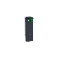
Variable Speed Drive - ATV930 - 75kW - 400/480V - with braking unit - IP21
This Altivar Process ATV900 variable speed drive can feed 3-phase synchronous and asynchronous power motors. It is suitable for motors with power rating up to 18.5kW/25hp for applications requiring slight overload (up to 120%). It is suitable for motors with power rating up to 15kW/20hp for applications requiring significant overload (up to 150%). It works at a rated supply voltage from 380V to 480V AC. This variable speed / frequency drive (VSD / VFD) is specifically designed for industrial processes. In the following market segments, oil and gas, mining, minerals and metals, food and beverage water and wastewater. It offers high motor performance on any motor and total control of any kind of coupling in master/slave applications. Network services help ensure operation continuity even in case of connection breakdown. Web server and data logging help reduce downtime through fast troubleshooting and preventive maintenance. Its advanced connectivity, including EtherNet/IP and Modbus TCP, allows deep integration into automation architectures. It is designed to be mounted in vertical position (+/- 10 °) on a wall.
Main
| Characteristic | Value(s) |
|---|---|
| Range of Product | Altivar Process ATV900 |
| Product Specific Application | Process for industrial |
| Product or Component Type | Variable speed drive |
| Variant | With braking chopper Standard version |
| Device Application | Industrial Application |
| Product destination | Asynchronous motors Synchronous motors |
| Phase | 3 phase |
| Mounting Mode | Wall mount |
| Continuous output current | 39.2 A 4 kHz normal duty 31.7 A 4 kHz heavy duty |
| Communication Port Protocol | Modbus TCP EtherNet/IP Modbus serial |
| Option card | Slot A communication module Profibus DP V1 Slot A communication module PROFINET Slot A communication module DeviceNet Slot A communication module EtherCAT Slot A communication module CANopen daisy chain RJ45 Slot A communication module CANopen SUB-D 9 Slot A communication module CANopen screw terminals Slot A/slot B/slot C digital and analog I/O extension module Slot A/slot B/slot C output relay extension module Slot B 5/12 V digital encoder interface module Slot B analog encoder interface module Slot B resolver encoder interface module communication module Ethernet Powerlink |
| [Us] rated supply voltage | 380...480 V - 15...10 % |
| [Us] rated supply voltage | 380...480 V |
| Relative symmetric mains voltage tolerance | 10 % |
| Relative symmetric network frequency tolerance | 5 % |
| nominal output current | 39.2 A |
| Motor power kW | 18.5 kW normal duty 15.0 kW heavy duty |
| EMC filter | Integrated With EMC plate option |
| IP degree of protection | IP21 |
| Degree of protection | UL type 1 |
Complementary
| Characteristic | Value(s) |
|---|---|
| Electrical connection | Control screw terminal 0.5...1.5 mm² AWG 20...AWG 16 Line side screw terminal 10...16 mm² AWG 8...AWG 6 Motor screw terminal 10...16 mm² AWG 8...AWG 6 DC bus screw terminal 10...16 mm² AWG 8...AWG 6 |
| Transmission Rate | 10/100 Mbit/s Ethernet IP/Modbus TCP 4.8, 9.6, 19.2, 38.4 kbit/s Modbus serial |
| Exchange mode | Half duplex, full duplex, autonegotiation Ethernet IP/Modbus TCP |
| Data format | 8 bits, configurable odd, even or no parity Modbus serial |
| Type of polarization | No impedance Modbus serial |
| Number of addresses | 1â¦247 Modbus serial |
| Supply | External supply for digital inputs 24 V DC 19â¦30 V), <1.25 mA overload and short-circuit protection Internal supply for reference potentiometer (1 to 10 kOhm) 10.5 V DC +/- 5 %, <10 mA overload and short-circuit protection Internal supply for digital inputs and STO 24 V DC 21â¦27 V), <200 mA overload and short-circuit protection |
| Local signalling | Local diagnostic: 3 LED (mono/dual colour) Embedded communication status: 5 LED (dual colour) Communication module status: 2 LED (dual colour) Presence of voltage: 1 LED (red) |
| Input compatibility | DI1...DI8 discrete input level 1 PLC IEC 61131-2 DI7, DI8 pulse input level 1 PLC IEC 65A-68 STOA, STOB discrete input level 1 PLC IEC 61131-2 |
| Discrete input logic | Positive logic (source) DI1...DI8), < 5 V, > 11 V Negative logic (sink) DI1...DI8), > 16 V, < 10 V Positive logic (source) DI7, DI8), < 0.6 V, > 2.5 V Positive logic (source) STOA, STOB), < 5 V, > 11 V |
| Sampling duration | 2 ms +/- 0.5 ms DI1...DI8) - discrete input 5 ms +/- 1 ms DI7, DI8) - pulse input 1 ms +/- 1 ms AI1, AI2, AI3) - analog input 5 ms +/- 1 ms AQ1, AQ2) - analog output |
| Accuracy | +/- 0.6 % AI1, AI2, AI3 for a temperature variation 60 °C analog input +/- 1 % AQ1, AQ2 for a temperature variation 60 °C analog output |
| Linearity error | AI1, AI2, AI3 +/- 0.15 % of maximum value analog input AQ1, AQ2 +/- 0.2 % analog output |
| Refresh time | Relay output R1, R2, R3)5 ms +/- 0.5 ms) |
| Isolation | Between power and control terminals |
| Discrete input number | 10 |
| Discrete input type | DI1...DI8 programmable, 24 V DC <= 30 V)3.5 kOhm DI7, DI8 programmable as pulse input 0â¦30 kHz, 24 V DC <= 30 V) STOA, STOB safe torque off, 24 V DC <= 30 V)> 2.2 kOhm |
| Discrete input logic | 16 preset speeds |
| Discrete output number | 2 |
| Discrete output type | Logic output DQ+ 0â¦1 kHz <= 30 V DC 100 mA Programmable as pulse output DQ+ 0â¦30 kHz <= 30 V DC 20 mA Logic output DQ- 0â¦1 kHz <= 30 V DC 100 mA |
| Analogue input number | 3 |
| Analogue input type | AI1, AI2, AI3 software-configurable voltage 0...10 V DC 30 kOhm 12 bits AI1, AI2, AI3 software-configurable current 0...20 mA/4...20 mA 250 Ohm 12 bits |
| Analogue output number | 2 |
| Analogue output type | Software-configurable voltage AQ1, AQ2 0...10 V DC 470 Ohm 10 bits Software-configurable current AQ1, AQ2 0...20 mA 500 Ohm 10 bits |
| Relay output number | 3 |
| Relay output type | Configurable relay logic R1 fault relay NO/NC 100000 cycles Configurable relay logic R2 sequence relay NO 1000000 cycles Configurable relay logic R3 sequence relay NO 1000000 cycles |
| Maximum switching current | Relay output R1 resistive, cos phi = 1 3 A 250 V AC Relay output R1 resistive, cos phi = 1 3 A 30 V DC Relay output R1 inductive, cos phi = 0.4 7 ms 2 A 250 V AC Relay output R1 inductive, cos phi = 0.4 7 ms 2 A 30 V DC Relay output R2, R3 resistive, cos phi = 1 5 A 250 V AC Relay output R2, R3 resistive, cos phi = 1 5 A 30 V DC Relay output R2, R3 inductive, cos phi = 0.4 7 ms 2 A 250 V AC Relay output R2, R3 inductive, cos phi = 0.4 7 ms 2 A 30 V DC |
| Minimum switching current | Relay output R1, R2, R3 5 mA 24 V DC |
| Physical interface | Ethernet 2-wire RS 485 |
| Connector Type | 2 RJ45 1 RJ45 |
| Method of access | Slave Modbus TCP |
| Transmission Rate | 10, 100 Mbits 4.8 kbps 9600 bit/s 19200 bit/s |
| Transmission frame | RTU |
| Number of addresses | 1â¦247 |
| Data format | 8 bits, configurable odd, even or no parity |
| Type of polarization | No impedance |
| 4 quadrant operation possible | True |
| Asynchronous motor control profile | Constant torque standard Variable torque standard Optimized torque mode |
| Synchronous motor control profile | Permanent magnet motor Synchronous reluctance motor |
| Maximum output frequency | 599 Hz |
| Acceleration and deceleration ramps | Linear adjustable separately from 0.01...9999 s |
| Motor slip compensation | Adjustable Automatic whatever the load Not available in permanent magnet motor law Can be suppressed |
| Switching frequency | 2...16 kHz adjustable 4...16 kHz with derating factor |
| Nominal switching frequency | 4 kHz |
| Braking to standstill | By DC injection |
| Brake chopper integrated | True |
| Line current | 33.4 A 380 V normal duty) 27.7 A 380 V heavy duty) 28.9 A 480 V normal duty) 24.4 A 480 V heavy duty) |
| Maximum Input Current per Phase | 33.4 A |
| Maximum output voltage | 480.0 V |
| Apparent power | 24 kVA 480 V normal duty) 20.3 kVA 480 V heavy duty) |
| Maximum transient current | 47 A 60 s normal duty) 47.6 A 60 s heavy duty) |
| Network Frequency | 50-60 Hz |
| Prospective line Isc | 50 kA |
| Base load current at high overload | 31.7 A |
| Base load current at low overload | 39.2 A |
| Power dissipation in W | Natural convection 67 W 380 V 4 kHz Forced convection 460 W 380 V 4 kHz |
| With safety function Safely Limited Speed (SLS) | True |
| With safety function Safe brake management (SBC/SBT) | True |
| With safety function Safe Operating Stop (SOS) | False |
| With safety function Safe Position (SP) | False |
| With safety function Safe programmable logic | False |
| With safety function Safe Speed Monitor (SSM) | False |
| With safety function Safe Stop 1 (SS1) | True |
| With sft fct Safe Stop 2 (SS2) | False |
| With safety function Safe torque off (STO) | True |
| With safety function Safely Limited Position (SLP) | False |
| With safety function Safe Direction (SDI) | False |
| Protection type | Thermal protection motor Safe torque off motor Motor phase break motor Thermal protection drive Safe torque off drive Overheating drive Overcurrent between output phases and earth drive Overload of output voltage drive Short-circuit protection drive Motor phase break drive Overvoltages on the DC bus drive Line supply overvoltage drive Line supply undervoltage drive Line supply phase loss drive Overspeed drive Break on the control circuit drive |
| Quantity per Set | 1 |
| Width | 8.3 in (211 mm) |
| Height | 21.5 in (545.9 mm) |
| Depth | 9.3 in (235 mm) |
| Product Weight | 31.3 lb(US) (14.2 kg) |

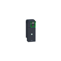
Variable Speed Drive - ATV930 - 2,2kW - 400/480V - with braking unit - IP21

BRAND NEW CONDITION, GUARANTEED.
PLC Direct is not an authorized distributor. We offer a broad range of in-stock products with minimal lead time.
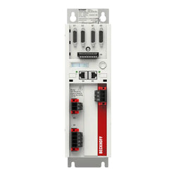
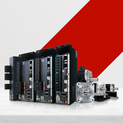
Digital Compact Servo Drive, 2-axis module, 100…480 V AC, rated output current 2 x 6 A, EtherCAT interface, OCT, hardware version 2.0, firmware version ? 2.10 (1)

Variable Speed Drive - ATV930 - 3kW - 400/480V - with braking unit - IP21

Variable Speed Drive ATV630 - 2.2kW/3hp - 380...480V - IP21/UL type 1
Main
| Characteristic | Value(s) |
|---|---|
| Range of Product | Altivar |
| Product or Component Type | Variable speed drive |
| Product Specific Application | Simple machine |
| Component name | ATV31 |
| Assembly style | With heat sink |
| Variant | With drive order potentiometer |
| EMC filter | Integrated |
| [Us] rated supply voltage | 380...500 V - 5...5 % |
| Supply frequency | 50...60 Hz - 5...5 % |
| Phase | 3 phase |
| Motor power kW | 0.37 kW 4 kHz |
| Maximum Horse Power Rating | 0.5 hp 4 kHz |
| Line current | 1.7 A 500 V 2.2 A 380 V, Isc = 1 kA |
| Apparent power | 1.5 kVA |
| Prospective line Isc | 1 kA |
| Nominal output current | 1.5 A 4 kHz |
| Maximum transient current | 2.3 A 60 s |
| Power dissipation in W | 32 W at nominal load |
| Asynchronous motor control profile | Factory set : constant torque Sensorless flux vector control with PWM type motor control signal |
| Analogue input number | 4 |
Complementary
| Characteristic | Value(s) |
|---|---|
| Product destination | Asynchronous motors |
| Supply voltage limits | 323â¦550 V |
| Network Frequency | 47.5...63 Hz |
| Output frequency | 0.0005â¦0.5 kHz |
| Nominal switching frequency | 4 kHz |
| Switching frequency | 2...16 kHz adjustable |
| Speed range | 1â¦50 |
| Transient overtorque | 150â¦170 % of nominal motor torque |
| Braking torque | <= 150 % 60 s with braking resistor 100 % with braking resistor continuously 150 % without braking resistor |
| Regulation loop | Frequency PI regulator |
| Motor slip compensation | Adjustable Suppressable Automatic whatever the load |
| Output voltage | <= power supply voltage |
| Electrical connection | Al1, Al2, Al3, AOV, AOC, R1A, R1B, R1C, R2A, R2B, LI1...LI6 terminal 0.004 in² (2.5 mm²) AWG 14 L1, L2, L3, U, V, W, PA, PB, PA/+, PC/- terminal 0.004 in² (2.5 mm²) AWG 14 |
| Tightening torque | Al1, Al2, Al3, AOV, AOC, R1A, R1B, R1C, R2A, R2B, LI1...LI6 5.3 lbf.in (0.6 N.m) L1, L2, L3, U, V, W, PA, PB, PA/+, PC/- 7.08 lbf.in (0.8 N.m) |
| Insulation | Electrical between power and control |
| Supply | Internal supply for logic inputs 19...30 V 100 mA overload and short-circuit protection Internal supply for reference potentiometer (2.2 to 10 kOhm) 10...10.8 V 10 mA overload and short-circuit protection |
| Analogue input type | AI3 configurable current 0...20 mA 250 Ohm AI1 configurable voltage 0...10 V 30 V max 30000 Ohm AI2 configurable voltage +/- 10 V 30 V max 30000 Ohm AIP potentiometer reference 8 ms 10 bits +/- 4.3 % +/- 0.2 % |
| Sampling duration | LI1...LI6 4 ms discrete AI1, AI2, AI3 8 ms analog |
| Response time | AOV, AOC 8 ms analog R1A, R1B, R1C, R2A, R2B 8 ms discrete |
| Linearity error | +/- 0.2 % output |
| Analogue output number | 2 |
| Analogue output type | AOC configurable current 0...20 mA 800 Ohm 8 bits AOV configurable voltage 0...10 V 470 Ohm 8 bits |
| Discrete input logic | Positive logic (source) LI1...LI6), < 5 V, > 11 V Logic input not wired LI1...LI4), < 13 V Negative logic (source) LI1...LI6), > 19 V |
| Discrete output number | 2 |
| Discrete output type | Configurable relay logic R1A, R1B, R1C) 1 NO + 1 NC - 100000 cycles Configurable relay logic R2A, R2B) NC - 100000 cycles |
| Minimum switching current | R1-R2 10 mA 5 V DC |
| Maximum switching current | R1-R2 2 A 250 V AC inductive, cos phi = 0.4 7 ms R1-R2 2 A 30 V DC inductive, cos phi = 0.4 7 ms R1-R2 5 A 250 V AC resistive, cos phi = 1 0 ms R1-R2 5 A 30 V DC resistive, cos phi = 1 0 ms |
| Discrete input number | 6 |
| Discrete input type | LI1...LI6) programmable 24 V, 0â¦100 mA PLC 3500 Ohm |
| Acceleration and deceleration ramps | S, U or customized Linear adjustable separately from 0.1 to 999.9 s |
| Braking to standstill | By DC injection |
| Protection type | Input phase breaks drive Line supply overvoltage and undervoltage safety circuits drive Line supply phase loss safety function, for three phases supply drive Motor phase breaks drive Overcurrent between output phases and earth (on power up only) drive Overheating protection drive Short-circuit between motor phases drive Thermal protection motor |
| Insulation resistance | >= 500 mOhm 500 V DC for 1 minute |
| Display type | 1 LED Red)drive voltage Four 7-segment display unitsCANopen bus status |
| Time constant | 5 ms for reference change |
| Frequency resolution | Display unit 0.1 Hz Analog input 0.1...100 Hz |
| Connector type | 1 RJ45 CANopen via VW3 CANTAP2 adaptor 1 RJ45 Modbus |
| Physical interface | RS485 multidrop serial link CANopen via VW3 CANTAP2 adaptor RS485 multidrop serial link Modbus |
| Transmission frame | RTU CANopen via VW3 CANTAP2 adaptor RTU Modbus |
| Transmission Rate | 10, 20, 50, 125, 250, 500 kbps or 1 Mbps CANopen via VW3 CANTAP2 adaptor 4800, 9600 or 19200 bps Modbus |
| Number of addresses | 1â¦127 CANopen via VW3 CANTAP2 adaptor 1â¦247 Modbus |
| Number of drive | 127 CANopen via VW3 CANTAP2 adaptor 31 Modbus |
| Marking | CE |
| Operating position | Vertical +/- 10 degree |
| Product Weight | 4.0 lb(US) (1.8 kg) |

BRAND NEW CONDITION, GUARANTEED.