
 1 year warranty


Ordering
1 piece
85364900
Popular Downloads
Dimensions
45 mm
72.5 mm
68 mm
0.22 kg
Technical
3
0
1
0
IEC 60947-1 / 60947-4-1 and EN 60947-1 / 60947-4-1, UL 508, CSA C22.2 N°14
Auxiliary Circuit 690 V
Main Circuit 690 V
Auxiliary Circuit 690 V
Main Circuit 690 V
Auxiliary Circuit 50 / 60 Hz
Main Circuit 50 / 60 Hz
Auxiliary Circuit 50 / 60 Hz
Main Circuit 50 / 60 Hz
acc. to IEC 60947-4-1, Open Contactors Θ = 40 °C 22 A
acc. to IEC 60947-5-1, Θ = 40 °C 10 A
acc. to IEC 60947-4-1, Open Contactors Θ = 40 °C 22 A
acc. to IEC 60947-5-1, Θ = 40 °C 10 A
(690 V) 40 °C 22 A
(690 V) 60 °C 18 A
(690 V) 70 °C 15 A
(690 V) 40 °C 22 A
(690 V) 60 °C 18 A
(690 V) 70 °C 15 A
(415 V) 60 °C 9 A
(440 V) 60 °C 8 A
(500 V) 60 °C 8 A
(690 V) 60 °C 5 A
(380 / 400 V) 60 °C 9 A
(220 / 230 / 240 V) 60 °C 9 A
(415 V) 60 °C 9 A
(440 V) 60 °C 8 A
(500 V) 60 °C 8 A
(690 V) 60 °C 5 A
(380 / 400 V) 60 °C 9 A
(220 / 230 / 240 V) 60 °C 9 A
(500 V) NC 2
(500 V) 2 A
(690 V) 2 A
(24 / 127 V) 6 A
(220 / 240 V) 4 A
(400 / 440 V) 3 A
(500 V) NC 2
(500 V) 2 A
(690 V) 2 A
(24 / 127 V) 6 A
(220 / 240 V) 4 A
(400 / 440 V) 3 A
(24 V) 6 A / 144 W
(48 V) 2.8 A / 134 W
(72 V) 1 A / 72 W
(110 V) 0.55 A / 60 W
(125 V) 0.55 A / 69 W
(220 V) 0.27 A / 60 W
(250 V) 0.27 A / 68 W
(24 V) 6 A / 144 W
(48 V) 2.8 A / 134 W
(72 V) 1 A / 72 W
(110 V) 0.55 A / 60 W
(125 V) 0.55 A / 69 W
(220 V) 0.27 A / 60 W
(250 V) 0.27 A / 68 W
(400 V) 4 kW
(415 V) 4 kW
(440 V) 4 kW
(500 V) 4 kW
(690 V) 4 kW
(220 / 230 / 240 V) 2.2 kW
(400 V) 4 kW
(415 V) 4 kW
(440 V) 4 kW
(500 V) 4 kW
(690 V) 4 kW
(220 / 230 / 240 V) 2.2 kW
at 40 °C Ambient Temp, in Free Air, from a Cold State 10 s 100 A
at 40 °C Ambient Temp, in Free Air, from a Cold State 15 min 22 A
at 40 °C Ambient Temp, in Free Air, from a Cold State 1 min 50 A
at 40 °C Ambient Temp, in Free Air, from a Cold State 1 s 230 A
at 40 °C Ambient Temp, in Free Air, from a Cold State 30 s 65 A
for 0.1 s 140 A
for 1 s 100 A
cos phi=0.45 (cos phi=0.35 for Ie > 100 A) at 440 V 155 A
cos phi=0.45 (cos phi=0.35 for Ie > 100 A) at 690 V 90 A
cos phi=0.45 (cos phi=0.35 for Ie > 100 A) at 440 V 155 A
cos phi=0.45 (cos phi=0.35 for Ie > 100 A) at 690 V 90 A
acc. to IEC 60947-4-1 and VDE 0110 (Gr. C) 690 V
acc. to IEC 60947-5-1 and VDE 0110 (Gr. C) 690 V
acc. to UL/CSA 600 V
acc. to IEC 60947-4-1 and VDE 0110 (Gr. C) 690 V
acc. to IEC 60947-5-1 and VDE 0110 (Gr. C) 690 V
acc. to UL/CSA 600 V
Auxiliary Circuit 6 kV
(AC-1) 600 cycles per hour
(AC-15) 1200 cycles per hour
(AC-2 / AC-4) 300 cycles per hour
(AC-3) 1200 cycles per hour
(DC-13) 900 cycles per hour
(AC-1) 600 cycles per hour
(AC-15) 1200 cycles per hour
(AC-2 / AC-4) 300 cycles per hour
(AC-3) 1200 cycles per hour
(DC-13) 900 cycles per hour
3600 cycles per hour
50 Hz 24 V
60 Hz 24 V
50 Hz 24 V
60 Hz 24 V
at Rated Operating Conditions AC-1 per Pole 1 W
at Rated Operating Conditions AC-3 per Pole 0.16 W
at Rated Operating Conditions AC-1 per Pole 1 W
at Rated Operating Conditions AC-3 per Pole 0.16 W
Between Coil De-energization and NC Contact Closing 7 ... 22 ms
Between Coil De-energization and NO Contact Opening 5 ... 19 ms
Between Coil Energization and NC Contact Opening 6 ... 18 ms
Between Coil Energization and NO Contact Closing 9 ... 24 ms
Between Coil De-energization and NC Contact Closing 7 ... 22 ms
Between Coil De-energization and NO Contact Opening 5 ... 19 ms
Between Coil Energization and NC Contact Opening 6 ... 18 ms
Between Coil Energization and NO Contact Closing 9 ... 24 ms
Flexible with Ferrule 1/2x 0.75 ... 2.5 mm²
Flexible with Insulated Ferrule 1x 0.75 ... 2.5 mm²
Flexible with Insulated Ferrule 2x 0.75 ... 1.5 mm²
Rigid 1/2x 0.75 ... 4 mm²
Flexible with Ferrule 1/2x 0.75 ... 2.5 mm²
Flexible with Insulated Ferrule 1x 0.75 ... 2.5 mm²
Flexible with Insulated Ferrule 2x 0.75 ... 1.5 mm²
Rigid 1/2x 0.75 ... 4 mm²
Flexible with Ferrule 1/2x 0.75 ... 2.5 mm²
Flexible with Insulated Ferrule 1x 0.75 ... 2.5 mm²
Flexible with Insulated Ferrule 2x 0.75 ... 1.5 mm²
Rigid 1/2x 0.75 ... 2.5 mm²
Flexible with Ferrule 1/2x 0.75 ... 2.5 mm²
Flexible with Insulated Ferrule 1x 0.75 ... 2.5 mm²
Flexible with Insulated Ferrule 2x 0.75 ... 1.5 mm²
Rigid 1/2x 0.75 ... 2.5 mm²
Flexible with Ferrule 1/2x 0.75 ... 2.5 mm²
Flexible with Insulated Ferrule 1x 0.75 ... 2.5 mm²
Flexible with Insulated Ferrule 2x 0.75 ... 1.5 mm²
Rigid 1/2x 0.75 ... 2.5 mm²
Flexible with Ferrule 1/2x 0.75 ... 2.5 mm²
Flexible with Insulated Ferrule 1x 0.75 ... 2.5 mm²
Flexible with Insulated Ferrule 2x 0.75 ... 1.5 mm²
Rigid 1/2x 0.75 ... 2.5 mm²
Auxiliary Circuit 9 mm
Control Circuit 9 mm
Main Circuit 9 mm
Auxiliary Circuit 9 mm
Control Circuit 9 mm
Main Circuit 9 mm
acc. to IEC 60529, IEC 60947-1, EN 60529 Auxiliary Terminals IP20
acc. to IEC 60529, IEC 60947-1, EN 60529 Coil Terminals IP20
acc. to IEC 60529, IEC 60947-1, EN 60529 Main Terminals IP20
acc. to IEC 60529, IEC 60947-1, EN 60529 Auxiliary Terminals IP20
acc. to IEC 60529, IEC 60947-1, EN 60529 Coil Terminals IP20
acc. to IEC 60529, IEC 60947-1, EN 60529 Main Terminals IP20
Auxiliary Circuit 1 N·m
Control Circuit 1 N·m
Main Circuit 1 N·m
Auxiliary Circuit 1 N·m
Control Circuit 1 N·m
Main Circuit 1 N·m
Screw Terminals
Block Contactor
Technical UL/CSA
(600 V AC) 20 A
(120 V AC) Single Phase 1/3 hp
(200 ... 208 V AC) Three Phase 2 hp
(220 ... 240 V AC) Three Phase 2 hp
(240 V AC) Single Phase 1 hp
(440 ... 480 V AC) Three Phase 5 hp
(550 ... 600 V AC) Three Phase 7.5 hp
(120 V AC) Single Phase 1/3 hp
(200 ... 208 V AC) Three Phase 2 hp
(220 ... 240 V AC) Three Phase 2 hp
(240 V AC) Single Phase 1 hp
(440 ... 480 V AC) Three Phase 5 hp
(550 ... 600 V AC) Three Phase 7.5 hp
Auxiliary Circuit 9 in·lb
Control Circuit 9 in·lb
Main Circuit 9 in·lb
Auxiliary Circuit 9 in·lb
Control Circuit 9 in·lb
Main Circuit 9 in·lb
(120 V AC) Single Phase 7.2 A
(200 ... 208 V AC) Three Phase 7.8 A
(220 ... 240 V AC) Three Phase 6.8 A
(240 V AC) Single Phase 8 A
(440 ... 480 V AC) Three Phase 7.6 A
(550 ... 600 V AC) Three Phase 9 A
(120 V AC) Single Phase 7.2 A
(200 ... 208 V AC) Three Phase 7.8 A
(220 ... 240 V AC) Three Phase 6.8 A
(240 V AC) Single Phase 8 A
(440 ... 480 V AC) Three Phase 7.6 A
(550 ... 600 V AC) Three Phase 9 A
Environmental
Close to Contactor Fitted with Thermal O/L Relay -25 ... 60 °C
Close to Contactor without Thermal O/L Relay -40 ... 70 °C
Close to Contactor for Storage -60 ... +80 °C
Close to Contactor Fitted with Thermal O/L Relay -25 ... 60 °C
Close to Contactor without Thermal O/L Relay -40 ... 70 °C
Close to Contactor for Storage -60 ... +80 °C
Category B according to IEC 60947-1 Annex Q
Without Derating 3000 m
Closed, Shock Direction: B1 10 g
Closed, Shock Direction: C1 20 g
Closed, Shock Direction: C2 20 g
Open, Shock Direction: B1 5 g
Open, Shock Direction: C1 9 g
Open, Shock Direction: C2 14 g
Shock Direction: A 20 g
Shock Direction: B2 15 g
Closed, Shock Direction: B1 10 g
Closed, Shock Direction: C1 20 g
Closed, Shock Direction: C2 20 g
Open, Shock Direction: B1 5 g
Open, Shock Direction: C1 9 g
Open, Shock Direction: C2 14 g
Shock Direction: A 20 g
Shock Direction: B2 15 g
3g Closed Position & 2g Open Position 5 ... 300 Hz
Material Compliance
Following EU Directive 2011/65/EU and Amendment 2015/863 July 22, 2019
Business To Business
5. Small Equipment (No External Dimension More Than 50 cm)
Certificates and Declarations
Container Information
box 1 piece
78 mm
80 mm
48 mm
0.22 kg
3471523032200
960 piece
External Classifications and Standards
Q
EC000066 - Power contactor, AC switching
EC000066 - Power contactor, AC switching
EC000066 - Power contactor, AC switching
V11.0 : 27371003
39121529
4761 >> Magnet contactor, AC-switching
3210507
Ordering
1 piece
85364900
Popular Downloads
Dimensions
45 mm
72.5 mm
68 mm
0.22 kg
Technical
3
0
1
0
IEC 60947-1 / 60947-4-1 and EN 60947-1 / 60947-4-1, UL 508, CSA C22.2 N°14
Auxiliary Circuit 690 V
Main Circuit 690 V
Auxiliary Circuit 690 V
Main Circuit 690 V
Auxiliary Circuit 50 / 60 Hz
Main Circuit 50 / 60 Hz
Auxiliary Circuit 50 / 60 Hz
Main Circuit 50 / 60 Hz
acc. to IEC 60947-4-1, Open Contactors Θ = 40 °C 22 A
acc. to IEC 60947-5-1, Θ = 40 °C 10 A
acc. to IEC 60947-4-1, Open Contactors Θ = 40 °C 22 A
acc. to IEC 60947-5-1, Θ = 40 °C 10 A
(690 V) 40 °C 22 A
(690 V) 60 °C 18 A
(690 V) 70 °C 15 A
(690 V) 40 °C 22 A
(690 V) 60 °C 18 A
(690 V) 70 °C 15 A
(415 V) 60 °C 9 A
(440 V) 60 °C 8 A
(500 V) 60 °C 8 A
(690 V) 60 °C 5 A
(380 / 400 V) 60 °C 9 A
(220 / 230 / 240 V) 60 °C 9 A
(415 V) 60 °C 9 A
(440 V) 60 °C 8 A
(500 V) 60 °C 8 A
(690 V) 60 °C 5 A
(380 / 400 V) 60 °C 9 A
(220 / 230 / 240 V) 60 °C 9 A
(500 V) NC 2
(500 V) 2 A
(690 V) 2 A
(24 / 127 V) 6 A
(220 / 240 V) 4 A
(400 / 440 V) 3 A
(500 V) NC 2
(500 V) 2 A
(690 V) 2 A
(24 / 127 V) 6 A
(220 / 240 V) 4 A
(400 / 440 V) 3 A
(24 V) 6 A / 144 W
(48 V) 2.8 A / 134 W
(72 V) 1 A / 72 W
(110 V) 0.55 A / 60 W
(125 V) 0.55 A / 69 W
(220 V) 0.27 A / 60 W
(250 V) 0.27 A / 68 W
(24 V) 6 A / 144 W
(48 V) 2.8 A / 134 W
(72 V) 1 A / 72 W
(110 V) 0.55 A / 60 W
(125 V) 0.55 A / 69 W
(220 V) 0.27 A / 60 W
(250 V) 0.27 A / 68 W
(400 V) 4 kW
(415 V) 4 kW
(440 V) 4 kW
(500 V) 4 kW
(690 V) 4 kW
(220 / 230 / 240 V) 2.2 kW
(400 V) 4 kW
(415 V) 4 kW
(440 V) 4 kW
(500 V) 4 kW
(690 V) 4 kW
(220 / 230 / 240 V) 2.2 kW
at 40 °C Ambient Temp, in Free Air, from a Cold State 10 s 100 A
at 40 °C Ambient Temp, in Free Air, from a Cold State 15 min 22 A
at 40 °C Ambient Temp, in Free Air, from a Cold State 1 min 50 A
at 40 °C Ambient Temp, in Free Air, from a Cold State 1 s 230 A
at 40 °C Ambient Temp, in Free Air, from a Cold State 30 s 65 A
for 0.1 s 140 A
for 1 s 100 A
at 40 °C Ambient Temp, in Free Air, from a Cold State 10 s 100 A
at 40 °C Ambient Temp, in Free Air, from a Cold State 15 min 22 A
at 40 °C Ambient Temp, in Free Air, from a Cold State 1 min 50 A
at 40 °C Ambient Temp, in Free Air, from a Cold State 1 s 230 A
at 40 °C Ambient Temp, in Free Air, from a Cold State 30 s 65 A
for 0.1 s 140 A
for 1 s 100 A
cos phi=0.45 (cos phi=0.35 for Ie > 100 A) at 440 V 155 A
cos phi=0.45 (cos phi=0.35 for Ie > 100 A) at 690 V 90 A
cos phi=0.45 (cos phi=0.35 for Ie > 100 A) at 440 V 155 A
cos phi=0.45 (cos phi=0.35 for Ie > 100 A) at 690 V 90 A
acc. to IEC 60947-4-1 and VDE 0110 (Gr. C) 690 V
acc. to IEC 60947-5-1 and VDE 0110 (Gr. C) 690 V
acc. to UL/CSA 600 V
acc. to IEC 60947-4-1 and VDE 0110 (Gr. C) 690 V
acc. to IEC 60947-5-1 and VDE 0110 (Gr. C) 690 V
acc. to UL/CSA 600 V
Auxiliary Circuit 6 kV
(AC-1) 600 cycles per hour
(AC-15) 1200 cycles per hour
(AC-2 / AC-4) 300 cycles per hour
(AC-3) 1200 cycles per hour
(DC-13) 900 cycles per hour
(AC-1) 600 cycles per hour
(AC-15) 1200 cycles per hour
(AC-2 / AC-4) 300 cycles per hour
(AC-3) 1200 cycles per hour
(DC-13) 900 cycles per hour
3600 cycles per hour
50 Hz 230 V
60 Hz 230 V
50 Hz 230 V
60 Hz 230 V
at Rated Operating Conditions AC-1 per Pole 1 W
at Rated Operating Conditions AC-3 per Pole 0.16 W
at Rated Operating Conditions AC-1 per Pole 1 W
at Rated Operating Conditions AC-3 per Pole 0.16 W
Between Coil De-energization and NC Contact Closing 7 ... 22 ms
Between Coil De-energization and NO Contact Opening 5 ... 19 ms
Between Coil Energization and NC Contact Opening 6 ... 18 ms
Between Coil Energization and NO Contact Closing 9 ... 24 ms
Between Coil De-energization and NC Contact Closing 7 ... 22 ms
Between Coil De-energization and NO Contact Opening 5 ... 19 ms
Between Coil Energization and NC Contact Opening 6 ... 18 ms
Between Coil Energization and NO Contact Closing 9 ... 24 ms
Flexible with Ferrule 1/2x 0.75 ... 2.5 mm²
Flexible with Insulated Ferrule 1x 0.75 ... 2.5 mm²
Flexible with Insulated Ferrule 2x 0.75 ... 1.5 mm²
Rigid 1/2x 0.75 ... 4 mm²
Flexible with Ferrule 1/2x 0.75 ... 2.5 mm²
Flexible with Insulated Ferrule 1x 0.75 ... 2.5 mm²
Flexible with Insulated Ferrule 2x 0.75 ... 1.5 mm²
Rigid 1/2x 0.75 ... 4 mm²
Flexible with Ferrule 1/2x 0.75 ... 2.5 mm²
Flexible with Insulated Ferrule 1x 0.75 ... 2.5 mm²
Flexible with Insulated Ferrule 2x 0.75 ... 1.5 mm²
Rigid 1/2x 0.75 ... 2.5 mm²
Flexible with Ferrule 1/2x 0.75 ... 2.5 mm²
Flexible with Insulated Ferrule 1x 0.75 ... 2.5 mm²
Flexible with Insulated Ferrule 2x 0.75 ... 1.5 mm²
Rigid 1/2x 0.75 ... 2.5 mm²
Flexible with Ferrule 1/2x 0.75 ... 2.5 mm²
Flexible with Insulated Ferrule 1x 0.75 ... 2.5 mm²
Flexible with Insulated Ferrule 2x 0.75 ... 1.5 mm²
Rigid 1/2x 0.75 ... 2.5 mm²
Flexible with Ferrule 1/2x 0.75 ... 2.5 mm²
Flexible with Insulated Ferrule 1x 0.75 ... 2.5 mm²
Flexible with Insulated Ferrule 2x 0.75 ... 1.5 mm²
Rigid 1/2x 0.75 ... 2.5 mm²
Auxiliary Circuit 9 mm
Control Circuit 9 mm
Main Circuit 9 mm
Auxiliary Circuit 9 mm
Control Circuit 9 mm
Main Circuit 9 mm
acc. to IEC 60529, IEC 60947-1, EN 60529 Auxiliary Terminals IP20
acc. to IEC 60529, IEC 60947-1, EN 60529 Coil Terminals IP20
acc. to IEC 60529, IEC 60947-1, EN 60529 Main Terminals IP20
acc. to IEC 60529, IEC 60947-1, EN 60529 Auxiliary Terminals IP20
acc. to IEC 60529, IEC 60947-1, EN 60529 Coil Terminals IP20
acc. to IEC 60529, IEC 60947-1, EN 60529 Main Terminals IP20
Auxiliary Circuit 1 N·m
Control Circuit 1 N·m
Main Circuit 1 N·m
Auxiliary Circuit 1 N·m
Control Circuit 1 N·m
Main Circuit 1 N·m
Screw Terminals
Block Contactor
Technical UL/CSA
(600 V AC) 20 A
(120 V AC) Single Phase 1/3 hp
(200 ... 208 V AC) Three Phase 2 hp
(220 ... 240 V AC) Three Phase 2 hp
(240 V AC) Single Phase 1 hp
(440 ... 480 V AC) Three Phase 5 hp
(550 ... 600 V AC) Three Phase 7.5 hp
(120 V AC) Single Phase 1/3 hp
(200 ... 208 V AC) Three Phase 2 hp
(220 ... 240 V AC) Three Phase 2 hp
(240 V AC) Single Phase 1 hp
(440 ... 480 V AC) Three Phase 5 hp
(550 ... 600 V AC) Three Phase 7.5 hp
Auxiliary Circuit 9 in·lb
Control Circuit 9 in·lb
Main Circuit 9 in·lb
Auxiliary Circuit 9 in·lb
Control Circuit 9 in·lb
Main Circuit 9 in·lb
(120 V AC) Single Phase 7.2 A
(200 ... 208 V AC) Three Phase 7.8 A
(220 ... 240 V AC) Three Phase 6.8 A
(240 V AC) Single Phase 8 A
(440 ... 480 V AC) Three Phase 7.6 A
(550 ... 600 V AC) Three Phase 9 A
(120 V AC) Single Phase 7.2 A
(200 ... 208 V AC) Three Phase 7.8 A
(220 ... 240 V AC) Three Phase 6.8 A
(240 V AC) Single Phase 8 A
(440 ... 480 V AC) Three Phase 7.6 A
(550 ... 600 V AC) Three Phase 9 A
Environmental
Close to Contactor Fitted with Thermal O/L Relay -25 ... 60 °C
Close to Contactor without Thermal O/L Relay -40 ... 70 °C
Close to Contactor for Storage -60 ... +80 °C
Close to Contactor Fitted with Thermal O/L Relay -25 ... 60 °C
Close to Contactor without Thermal O/L Relay -40 ... 70 °C
Close to Contactor for Storage -60 ... +80 °C
Category B according to IEC 60947-1 Annex Q
Without Derating 3000 m
Closed, Shock Direction: B1 10 g
Closed, Shock Direction: C1 20 g
Closed, Shock Direction: C2 20 g
Open, Shock Direction: B1 5 g
Open, Shock Direction: C1 9 g
Open, Shock Direction: C2 14 g
Shock Direction: A 20 g
Shock Direction: B2 15 g
Closed, Shock Direction: B1 10 g
Closed, Shock Direction: C1 20 g
Closed, Shock Direction: C2 20 g
Open, Shock Direction: B1 5 g
Open, Shock Direction: C1 9 g
Open, Shock Direction: C2 14 g
Shock Direction: A 20 g
Shock Direction: B2 15 g
3g Closed Position & 2g Open Position 5 ... 300 Hz
Material Compliance
Following EU Directive 2011/65/EU and Amendment 2015/863 July 22, 2019
Business To Business
5. Small Equipment (No External Dimension More Than 50 cm)
Certificates and Declarations
Container Information
box 1 piece
78 mm
80 mm
48 mm
0.22 kg
3471523032262
960 piece
External Classifications and Standards
Q
EC000066 - Power contactor, AC switching
EC000066 - Power contactor, AC switching
EC000066 - Power contactor, AC switching
V11.0 : 27371003
39121529
4761 >> Magnet contactor, AC-switching
3210508

Ordering
1 piece
85364900
Popular Downloads
Dimensions
45 mm
72.5 mm
68 mm
0.28 kg
Technical
3
0
0
1
IEC 60947-1 / 60947-4-1 and EN 60947-1 / 60947-4-1, UL 508, CSA C22.2 N°14
Auxiliary Circuit 690 V
Main Circuit 690 V
Auxiliary Circuit 690 V
Main Circuit 690 V
Auxiliary Circuit 50 / 60 Hz
Main Circuit 50 / 60 Hz
Auxiliary Circuit 50 / 60 Hz
Main Circuit 50 / 60 Hz
acc. to IEC 60947-4-1, Open Contactors Θ = 40 °C 22 A
acc. to IEC 60947-5-1, Θ = 40 °C 10 A
acc. to IEC 60947-4-1, Open Contactors Θ = 40 °C 22 A
acc. to IEC 60947-5-1, Θ = 40 °C 10 A
(690 V) 40 °C 22 A
(690 V) 60 °C 18 A
(690 V) 70 °C 15 A
(690 V) 40 °C 22 A
(690 V) 60 °C 18 A
(690 V) 70 °C 15 A
(415 V) 60 °C 9 A
(440 V) 60 °C 8 A
(500 V) 60 °C 8 A
(690 V) 60 °C 5 A
(380 / 400 V) 60 °C 9 A
(220 / 230 / 240 V) 60 °C 9 A
(415 V) 60 °C 9 A
(440 V) 60 °C 8 A
(500 V) 60 °C 8 A
(690 V) 60 °C 5 A
(380 / 400 V) 60 °C 9 A
(220 / 230 / 240 V) 60 °C 9 A
(500 V) NC 2
(500 V) 2 A
(690 V) 2 A
(24 / 127 V) 6 A
(220 / 240 V) 4 A
(400 / 440 V) 3 A
(500 V) NC 2
(500 V) 2 A
(690 V) 2 A
(24 / 127 V) 6 A
(220 / 240 V) 4 A
(400 / 440 V) 3 A
(24 V) 6 A / 144 W
(48 V) 2.8 A / 134 W
(72 V) 1 A / 72 W
(110 V) 0.55 A / 60 W
(125 V) 0.55 A / 69 W
(220 V) 0.27 A / 60 W
(250 V) 0.27 A / 68 W
(24 V) 6 A / 144 W
(48 V) 2.8 A / 134 W
(72 V) 1 A / 72 W
(110 V) 0.55 A / 60 W
(125 V) 0.55 A / 69 W
(220 V) 0.27 A / 60 W
(250 V) 0.27 A / 68 W
(400 V) 4 kW
(415 V) 4 kW
(440 V) 4 kW
(500 V) 4 kW
(690 V) 4 kW
(220 / 230 / 240 V) 2.2 kW
(400 V) 4 kW
(415 V) 4 kW
(440 V) 4 kW
(500 V) 4 kW
(690 V) 4 kW
(220 / 230 / 240 V) 2.2 kW
at 40 °C Ambient Temp, in Free Air, from a Cold State 10 s 100 A
at 40 °C Ambient Temp, in Free Air, from a Cold State 15 min 22 A
at 40 °C Ambient Temp, in Free Air, from a Cold State 1 min 50 A
at 40 °C Ambient Temp, in Free Air, from a Cold State 1 s 230 A
at 40 °C Ambient Temp, in Free Air, from a Cold State 30 s 65 A
for 0.1 s 140 A
for 1 s 100 A
at 40 °C Ambient Temp, in Free Air, from a Cold State 10 s 100 A
at 40 °C Ambient Temp, in Free Air, from a Cold State 15 min 22 A
at 40 °C Ambient Temp, in Free Air, from a Cold State 1 min 50 A
at 40 °C Ambient Temp, in Free Air, from a Cold State 1 s 230 A
at 40 °C Ambient Temp, in Free Air, from a Cold State 30 s 65 A
for 0.1 s 140 A
for 1 s 100 A
cos phi=0.45 (cos phi=0.35 for Ie > 100 A) at 440 V 155 A
cos phi=0.45 (cos phi=0.35 for Ie > 100 A) at 690 V 90 A
cos phi=0.45 (cos phi=0.35 for Ie > 100 A) at 440 V 155 A
cos phi=0.45 (cos phi=0.35 for Ie > 100 A) at 690 V 90 A
acc. to IEC 60947-4-1 and VDE 0110 (Gr. C) 690 V
acc. to IEC 60947-5-1 and VDE 0110 (Gr. C) 690 V
acc. to UL/CSA 600 V
acc. to IEC 60947-4-1 and VDE 0110 (Gr. C) 690 V
acc. to IEC 60947-5-1 and VDE 0110 (Gr. C) 690 V
acc. to UL/CSA 600 V
Auxiliary Circuit 6 kV
(AC-1) 600 cycles per hour
(AC-15) 1200 cycles per hour
(AC-2 / AC-4) 300 cycles per hour
(AC-3) 1200 cycles per hour
(DC-13) 900 cycles per hour
(AC-1) 600 cycles per hour
(AC-15) 1200 cycles per hour
(AC-2 / AC-4) 300 cycles per hour
(AC-3) 1200 cycles per hour
(DC-13) 900 cycles per hour
3600 cycles per hour
DC Operation 24 V
at Rated Operating Conditions AC-1 per Pole 1 W
at Rated Operating Conditions AC-3 per Pole 0.16 W
at Rated Operating Conditions AC-1 per Pole 1 W
at Rated Operating Conditions AC-3 per Pole 0.16 W
Between Coil De-energization and NC Contact Closing 15 ... 20 ms
Between Coil De-energization and NO Contact Opening 13 ... 17 ms
Between Coil Energization and NC Contact Opening 31 ... 53 ms
Between Coil Energization and NO Contact Closing 36 ... 59 ms
Between Coil De-energization and NC Contact Closing 15 ... 20 ms
Between Coil De-energization and NO Contact Opening 13 ... 17 ms
Between Coil Energization and NC Contact Opening 31 ... 53 ms
Between Coil Energization and NO Contact Closing 36 ... 59 ms
Flexible with Ferrule 1/2x 0.75 ... 2.5 mm²
Flexible with Insulated Ferrule 1x 0.75 ... 2.5 mm²
Flexible with Insulated Ferrule 2x 0.75 ... 1.5 mm²
Rigid 1/2x 0.75 ... 4 mm²
Flexible with Ferrule 1/2x 0.75 ... 2.5 mm²
Flexible with Insulated Ferrule 1x 0.75 ... 2.5 mm²
Flexible with Insulated Ferrule 2x 0.75 ... 1.5 mm²
Rigid 1/2x 0.75 ... 4 mm²
Flexible with Ferrule 1/2x 0.75 ... 2.5 mm²
Flexible with Insulated Ferrule 1x 0.75 ... 2.5 mm²
Flexible with Insulated Ferrule 2x 0.75 ... 1.5 mm²
Rigid 1/2x 0.75 ... 2.5 mm²
Flexible with Ferrule 1/2x 0.75 ... 2.5 mm²
Flexible with Insulated Ferrule 1x 0.75 ... 2.5 mm²
Flexible with Insulated Ferrule 2x 0.75 ... 1.5 mm²
Rigid 1/2x 0.75 ... 2.5 mm²
Flexible with Ferrule 1/2x 0.75 ... 2.5 mm²
Flexible with Insulated Ferrule 1x 0.75 ... 2.5 mm²
Flexible with Insulated Ferrule 2x 0.75 ... 1.5 mm²
Rigid 1/2x 0.75 ... 2.5 mm²
Flexible with Ferrule 1/2x 0.75 ... 2.5 mm²
Flexible with Insulated Ferrule 1x 0.75 ... 2.5 mm²
Flexible with Insulated Ferrule 2x 0.75 ... 1.5 mm²
Rigid 1/2x 0.75 ... 2.5 mm²
Auxiliary Circuit 9 mm
Control Circuit 9 mm
Main Circuit 9 mm
Auxiliary Circuit 9 mm
Control Circuit 9 mm
Main Circuit 9 mm
acc. to IEC 60529, IEC 60947-1, EN 60529 Auxiliary Terminals IP20
acc. to IEC 60529, IEC 60947-1, EN 60529 Coil Terminals IP20
acc. to IEC 60529, IEC 60947-1, EN 60529 Main Terminals IP20
acc. to IEC 60529, IEC 60947-1, EN 60529 Auxiliary Terminals IP20
acc. to IEC 60529, IEC 60947-1, EN 60529 Coil Terminals IP20
acc. to IEC 60529, IEC 60947-1, EN 60529 Main Terminals IP20
Auxiliary Circuit 1 N·m
Control Circuit 1 N·m
Main Circuit 1 N·m
Auxiliary Circuit 1 N·m
Control Circuit 1 N·m
Main Circuit 1 N·m
Screw Terminals
Block Contactor
Technical UL/CSA
(600 V AC) 20 A
(120 V AC) Single Phase 1/3 hp
(200 ... 208 V AC) Three Phase 2 hp
(220 ... 240 V AC) Three Phase 2 hp
(240 V AC) Single Phase 1 hp
(440 ... 480 V AC) Three Phase 5 hp
(550 ... 600 V AC) Three Phase 7.5 hp
(120 V AC) Single Phase 1/3 hp
(200 ... 208 V AC) Three Phase 2 hp
(220 ... 240 V AC) Three Phase 2 hp
(240 V AC) Single Phase 1 hp
(440 ... 480 V AC) Three Phase 5 hp
(550 ... 600 V AC) Three Phase 7.5 hp
Auxiliary Circuit 9 in·lb
Control Circuit 9 in·lb
Main Circuit 9 in·lb
Auxiliary Circuit 9 in·lb
Control Circuit 9 in·lb
Main Circuit 9 in·lb
(120 V AC) Single Phase 7.2 A
(200 ... 208 V AC) Three Phase 7.8 A
(220 ... 240 V AC) Three Phase 6.8 A
(240 V AC) Single Phase 8 A
(440 ... 480 V AC) Three Phase 7.6 A
(550 ... 600 V AC) Three Phase 9 A
(120 V AC) Single Phase 7.2 A
(200 ... 208 V AC) Three Phase 7.8 A
(220 ... 240 V AC) Three Phase 6.8 A
(240 V AC) Single Phase 8 A
(440 ... 480 V AC) Three Phase 7.6 A
(550 ... 600 V AC) Three Phase 9 A
Environmental
Close to Contactor Fitted with Thermal O/L Relay -25 ... 60 °C
Close to Contactor without Thermal O/L Relay -40 ... 70 °C
Close to Contactor for Storage -60 ... +80 °C
Close to Contactor Fitted with Thermal O/L Relay -25 ... 60 °C
Close to Contactor without Thermal O/L Relay -40 ... 70 °C
Close to Contactor for Storage -60 ... +80 °C
Category B according to IEC 60947-1 Annex Q
Without Derating 3000 m
Closed, Shock Direction: B1 10 g
Closed, Shock Direction: C1 20 g
Closed, Shock Direction: C2 20 g
Open, Shock Direction: B1 5 g
Open, Shock Direction: C1 9 g
Open, Shock Direction: C2 14 g
Shock Direction: A 20 g
Shock Direction: B2 15 g
Closed, Shock Direction: B1 10 g
Closed, Shock Direction: C1 20 g
Closed, Shock Direction: C2 20 g
Open, Shock Direction: B1 5 g
Open, Shock Direction: C1 9 g
Open, Shock Direction: C2 14 g
Shock Direction: A 20 g
Shock Direction: B2 15 g
3g Closed Position & 2g Open Position 5 ... 300 Hz
Material Compliance
Following EU Directive 2011/65/EU and Amendment 2015/863 July 22, 2019
Business To Business
5. Small Equipment (No External Dimension More Than 50 cm)
Certificates and Declarations
Container Information
box 1 piece
78 mm
80 mm
48 mm
0.28 kg
3471523059313
960 piece
External Classifications and Standards
Q
EC000066 - Power contactor, AC switching
EC000066 - Power contactor, AC switching
EC002552 - Power contactor, DC switching
V11.0 : 27371018
39121529
4763 >> Power contactor, DC switching
3210522
Ordering
1 piece
85364900
Popular Downloads
Dimensions
45 mm
72.5 mm
68 mm
0.28 kg
Technical
3
0
1
0
IEC 60947-1 / 60947-4-1 and EN 60947-1 / 60947-4-1, UL 508, CSA C22.2 N°14
Auxiliary Circuit 690 V
Main Circuit 690 V
Auxiliary Circuit 690 V
Main Circuit 690 V
Auxiliary Circuit 50 / 60 Hz
Main Circuit 50 / 60 Hz
Auxiliary Circuit 50 / 60 Hz
Main Circuit 50 / 60 Hz
acc. to IEC 60947-4-1, Open Contactors Θ = 40 °C 22 A
acc. to IEC 60947-5-1, Θ = 40 °C 10 A
acc. to IEC 60947-4-1, Open Contactors Θ = 40 °C 22 A
acc. to IEC 60947-5-1, Θ = 40 °C 10 A
(690 V) 40 °C 22 A
(690 V) 60 °C 18 A
(690 V) 70 °C 15 A
(690 V) 40 °C 22 A
(690 V) 60 °C 18 A
(690 V) 70 °C 15 A
(415 V) 60 °C 9 A
(440 V) 60 °C 8 A
(500 V) 60 °C 8 A
(690 V) 60 °C 5 A
(380 / 400 V) 60 °C 9 A
(220 / 230 / 240 V) 60 °C 9 A
(415 V) 60 °C 9 A
(440 V) 60 °C 8 A
(500 V) 60 °C 8 A
(690 V) 60 °C 5 A
(380 / 400 V) 60 °C 9 A
(220 / 230 / 240 V) 60 °C 9 A
(500 V) NC 2
(500 V) 2 A
(690 V) 2 A
(24 / 127 V) 6 A
(220 / 240 V) 4 A
(400 / 440 V) 3 A
(500 V) NC 2
(500 V) 2 A
(690 V) 2 A
(24 / 127 V) 6 A
(220 / 240 V) 4 A
(400 / 440 V) 3 A
(24 V) 6 A / 144 W
(48 V) 2.8 A / 134 W
(72 V) 1 A / 72 W
(110 V) 0.55 A / 60 W
(125 V) 0.55 A / 69 W
(220 V) 0.27 A / 60 W
(250 V) 0.27 A / 68 W
(24 V) 6 A / 144 W
(48 V) 2.8 A / 134 W
(72 V) 1 A / 72 W
(110 V) 0.55 A / 60 W
(125 V) 0.55 A / 69 W
(220 V) 0.27 A / 60 W
(250 V) 0.27 A / 68 W
(400 V) 4 kW
(415 V) 4 kW
(440 V) 4 kW
(500 V) 4 kW
(690 V) 4 kW
(220 / 230 / 240 V) 2.2 kW
(400 V) 4 kW
(415 V) 4 kW
(440 V) 4 kW
(500 V) 4 kW
(690 V) 4 kW
(220 / 230 / 240 V) 2.2 kW
at 40 °C Ambient Temp, in Free Air, from a Cold State 10 s 100 A
at 40 °C Ambient Temp, in Free Air, from a Cold State 15 min 22 A
at 40 °C Ambient Temp, in Free Air, from a Cold State 1 min 50 A
at 40 °C Ambient Temp, in Free Air, from a Cold State 1 s 230 A
at 40 °C Ambient Temp, in Free Air, from a Cold State 30 s 65 A
for 0.1 s 140 A
for 1 s 100 A
at 40 °C Ambient Temp, in Free Air, from a Cold State 10 s 100 A
at 40 °C Ambient Temp, in Free Air, from a Cold State 15 min 22 A
at 40 °C Ambient Temp, in Free Air, from a Cold State 1 min 50 A
at 40 °C Ambient Temp, in Free Air, from a Cold State 1 s 230 A
at 40 °C Ambient Temp, in Free Air, from a Cold State 30 s 65 A
for 0.1 s 140 A
for 1 s 100 A
cos phi=0.45 (cos phi=0.35 for Ie > 100 A) at 440 V 155 A
cos phi=0.45 (cos phi=0.35 for Ie > 100 A) at 690 V 90 A
cos phi=0.45 (cos phi=0.35 for Ie > 100 A) at 440 V 155 A
cos phi=0.45 (cos phi=0.35 for Ie > 100 A) at 690 V 90 A
acc. to IEC 60947-4-1 and VDE 0110 (Gr. C) 690 V
acc. to IEC 60947-5-1 and VDE 0110 (Gr. C) 690 V
acc. to UL/CSA 600 V
acc. to IEC 60947-4-1 and VDE 0110 (Gr. C) 690 V
acc. to IEC 60947-5-1 and VDE 0110 (Gr. C) 690 V
acc. to UL/CSA 600 V
Auxiliary Circuit 6 kV
(AC-1) 600 cycles per hour
(AC-15) 1200 cycles per hour
(AC-2 / AC-4) 300 cycles per hour
(AC-3) 1200 cycles per hour
(DC-13) 900 cycles per hour
(AC-1) 600 cycles per hour
(AC-15) 1200 cycles per hour
(AC-2 / AC-4) 300 cycles per hour
(AC-3) 1200 cycles per hour
(DC-13) 900 cycles per hour
3600 cycles per hour
DC Operation 24 V
at Rated Operating Conditions AC-1 per Pole 1 W
at Rated Operating Conditions AC-3 per Pole 0.16 W
at Rated Operating Conditions AC-1 per Pole 1 W
at Rated Operating Conditions AC-3 per Pole 0.16 W
Between Coil De-energization and NC Contact Closing 15 ... 20 ms
Between Coil De-energization and NO Contact Opening 13 ... 17 ms
Between Coil Energization and NC Contact Opening 31 ... 53 ms
Between Coil Energization and NO Contact Closing 36 ... 59 ms
Between Coil De-energization and NC Contact Closing 15 ... 20 ms
Between Coil De-energization and NO Contact Opening 13 ... 17 ms
Between Coil Energization and NC Contact Opening 31 ... 53 ms
Between Coil Energization and NO Contact Closing 36 ... 59 ms
Flexible with Ferrule 1/2x 0.75 ... 2.5 mm²
Flexible with Insulated Ferrule 1x 0.75 ... 2.5 mm²
Flexible with Insulated Ferrule 2x 0.75 ... 1.5 mm²
Rigid 1/2x 0.75 ... 4 mm²
Flexible with Ferrule 1/2x 0.75 ... 2.5 mm²
Flexible with Insulated Ferrule 1x 0.75 ... 2.5 mm²
Flexible with Insulated Ferrule 2x 0.75 ... 1.5 mm²
Rigid 1/2x 0.75 ... 4 mm²
Flexible with Ferrule 1/2x 0.75 ... 2.5 mm²
Flexible with Insulated Ferrule 1x 0.75 ... 2.5 mm²
Flexible with Insulated Ferrule 2x 0.75 ... 1.5 mm²
Rigid 1/2x 0.75 ... 2.5 mm²
Flexible with Ferrule 1/2x 0.75 ... 2.5 mm²
Flexible with Insulated Ferrule 1x 0.75 ... 2.5 mm²
Flexible with Insulated Ferrule 2x 0.75 ... 1.5 mm²
Rigid 1/2x 0.75 ... 2.5 mm²
Flexible with Ferrule 1/2x 0.75 ... 2.5 mm²
Flexible with Insulated Ferrule 1x 0.75 ... 2.5 mm²
Flexible with Insulated Ferrule 2x 0.75 ... 1.5 mm²
Rigid 1/2x 0.75 ... 2.5 mm²
Flexible with Ferrule 1/2x 0.75 ... 2.5 mm²
Flexible with Insulated Ferrule 1x 0.75 ... 2.5 mm²
Flexible with Insulated Ferrule 2x 0.75 ... 1.5 mm²
Rigid 1/2x 0.75 ... 2.5 mm²
Auxiliary Circuit 9 mm
Control Circuit 9 mm
Main Circuit 9 mm
Auxiliary Circuit 9 mm
Control Circuit 9 mm
Main Circuit 9 mm
acc. to IEC 60529, IEC 60947-1, EN 60529 Auxiliary Terminals IP20
acc. to IEC 60529, IEC 60947-1, EN 60529 Coil Terminals IP20
acc. to IEC 60529, IEC 60947-1, EN 60529 Main Terminals IP20
acc. to IEC 60529, IEC 60947-1, EN 60529 Auxiliary Terminals IP20
acc. to IEC 60529, IEC 60947-1, EN 60529 Coil Terminals IP20
acc. to IEC 60529, IEC 60947-1, EN 60529 Main Terminals IP20
Auxiliary Circuit 1 N·m
Control Circuit 1 N·m
Main Circuit 1 N·m
Auxiliary Circuit 1 N·m
Control Circuit 1 N·m
Main Circuit 1 N·m
Screw Terminals
Block Contactor
Technical UL/CSA
(600 V AC) 20 A
(120 V AC) Single Phase 1/3 hp
(200 ... 208 V AC) Three Phase 2 hp
(220 ... 240 V AC) Three Phase 2 hp
(240 V AC) Single Phase 1 hp
(440 ... 480 V AC) Three Phase 5 hp
(550 ... 600 V AC) Three Phase 7.5 hp
(120 V AC) Single Phase 1/3 hp
(200 ... 208 V AC) Three Phase 2 hp
(220 ... 240 V AC) Three Phase 2 hp
(240 V AC) Single Phase 1 hp
(440 ... 480 V AC) Three Phase 5 hp
(550 ... 600 V AC) Three Phase 7.5 hp
Auxiliary Circuit 9 in·lb
Control Circuit 9 in·lb
Main Circuit 9 in·lb
Auxiliary Circuit 9 in·lb
Control Circuit 9 in·lb
Main Circuit 9 in·lb
(120 V AC) Single Phase 7.2 A
(200 ... 208 V AC) Three Phase 7.8 A
(220 ... 240 V AC) Three Phase 6.8 A
(240 V AC) Single Phase 8 A
(440 ... 480 V AC) Three Phase 7.6 A
(550 ... 600 V AC) Three Phase 9 A
(120 V AC) Single Phase 7.2 A
(200 ... 208 V AC) Three Phase 7.8 A
(220 ... 240 V AC) Three Phase 6.8 A
(240 V AC) Single Phase 8 A
(440 ... 480 V AC) Three Phase 7.6 A
(550 ... 600 V AC) Three Phase 9 A
Environmental
Close to Contactor Fitted with Thermal O/L Relay -25 ... 60 °C
Close to Contactor without Thermal O/L Relay -40 ... 70 °C
Close to Contactor for Storage -60 ... +80 °C
Close to Contactor Fitted with Thermal O/L Relay -25 ... 60 °C
Close to Contactor without Thermal O/L Relay -40 ... 70 °C
Close to Contactor for Storage -60 ... +80 °C
Category B according to IEC 60947-1 Annex Q
Without Derating 3000 m
Closed, Shock Direction: B1 10 g
Closed, Shock Direction: C1 20 g
Closed, Shock Direction: C2 20 g
Open, Shock Direction: B1 5 g
Open, Shock Direction: C1 9 g
Open, Shock Direction: C2 14 g
Shock Direction: A 20 g
Shock Direction: B2 15 g
Closed, Shock Direction: B1 10 g
Closed, Shock Direction: C1 20 g
Closed, Shock Direction: C2 20 g
Open, Shock Direction: B1 5 g
Open, Shock Direction: C1 9 g
Open, Shock Direction: C2 14 g
Shock Direction: A 20 g
Shock Direction: B2 15 g
3g Closed Position & 2g Open Position 5 ... 300 Hz
Material Compliance
Following EU Directive 2011/65/EU and Amendment 2015/863 July 22, 2019
Business To Business
5. Small Equipment (No External Dimension More Than 50 cm)
Certificates and Declarations
Container Information
box 1 piece
78 mm
80 mm
48 mm
0.28 kg
3471523059214
960 piece
External Classifications and Standards
Q
EC000066 - Power contactor, AC switching
EC000066 - Power contactor, AC switching
EC002552 - Power contactor, DC switching
V11.0 : 27371018
39121529
4763 >> Power contactor, DC switching
3210521

Ordering
1 piece
85364900
Popular Downloads
Dimensions
45 mm
72.5 mm
68 mm
0.22 kg
Technical
3
0
0
1
IEC 60947-1 / 60947-4-1 and EN 60947-1 / 60947-4-1, UL 508, CSA C22.2 N°14
Auxiliary Circuit 690 V
Main Circuit 690 V
Auxiliary Circuit 690 V
Main Circuit 690 V
Auxiliary Circuit 50 / 60 Hz
Main Circuit 50 / 60 Hz
Auxiliary Circuit 50 / 60 Hz
Main Circuit 50 / 60 Hz
acc. to IEC 60947-4-1, Open Contactors Θ = 40 °C 25 A
acc. to IEC 60947-5-1, Θ = 40 °C 10 A
acc. to IEC 60947-4-1, Open Contactors Θ = 40 °C 25 A
acc. to IEC 60947-5-1, Θ = 40 °C 10 A
(690 V) 40 °C 24 A
(690 V) 60 °C 20 A
(690 V) 70 °C 16 A
(690 V) 40 °C 24 A
(690 V) 60 °C 20 A
(690 V) 70 °C 16 A
(415 V) 60 °C 12 A
(440 V) 60 °C 11 A
(500 V) 60 °C 11 A
(690 V) 60 °C 7 A
(380 / 400 V) 60 °C 12 A
(220 / 230 / 240 V) 60 °C 12 A
(415 V) 60 °C 12 A
(440 V) 60 °C 11 A
(500 V) 60 °C 11 A
(690 V) 60 °C 7 A
(380 / 400 V) 60 °C 12 A
(220 / 230 / 240 V) 60 °C 12 A
(500 V) NC 2
(500 V) 2 A
(690 V) 2 A
(24 / 127 V) 6 A
(220 / 240 V) 4 A
(400 / 440 V) 3 A
(500 V) NC 2
(500 V) 2 A
(690 V) 2 A
(24 / 127 V) 6 A
(220 / 240 V) 4 A
(400 / 440 V) 3 A
(24 V) 6 A / 144 W
(48 V) 2.8 A / 134 W
(72 V) 1 A / 72 W
(110 V) 0.55 A / 60 W
(125 V) 0.55 A / 69 W
(220 V) 0.27 A / 60 W
(250 V) 0.27 A / 68 W
(24 V) 6 A / 144 W
(48 V) 2.8 A / 134 W
(72 V) 1 A / 72 W
(110 V) 0.55 A / 60 W
(125 V) 0.55 A / 69 W
(220 V) 0.27 A / 60 W
(250 V) 0.27 A / 68 W
(400 V) 5.5 kW
(415 V) 5.5 kW
(440 V) 5.5 kW
(500 V) 5.5 kW
(690 V) 5.5 kW
(220 / 230 / 240 V) 3 kW
(400 V) 5.5 kW
(415 V) 5.5 kW
(440 V) 5.5 kW
(500 V) 5.5 kW
(690 V) 5.5 kW
(220 / 230 / 240 V) 3 kW
at 40 °C Ambient Temp, in Free Air, from a Cold State 10 s 124 A
at 40 °C Ambient Temp, in Free Air, from a Cold State 15 min 24 A
at 40 °C Ambient Temp, in Free Air, from a Cold State 1 min 55 A
at 40 °C Ambient Temp, in Free Air, from a Cold State 1 s 250 A
at 40 °C Ambient Temp, in Free Air, from a Cold State 30 s 75 A
for 0.1 s 140 A
for 1 s 100 A
cos phi=0.45 (cos phi=0.35 for Ie > 100 A) at 440 V 155 A
cos phi=0.45 (cos phi=0.35 for Ie > 100 A) at 690 V 90 A
cos phi=0.45 (cos phi=0.35 for Ie > 100 A) at 440 V 155 A
cos phi=0.45 (cos phi=0.35 for Ie > 100 A) at 690 V 90 A
acc. to IEC 60947-4-1 and VDE 0110 (Gr. C) 690 V
acc. to IEC 60947-5-1 and VDE 0110 (Gr. C) 690 V
acc. to UL/CSA 600 V
acc. to IEC 60947-4-1 and VDE 0110 (Gr. C) 690 V
acc. to IEC 60947-5-1 and VDE 0110 (Gr. C) 690 V
acc. to UL/CSA 600 V
Auxiliary Circuit 6 kV
(AC-1) 600 cycles per hour
(AC-15) 1200 cycles per hour
(AC-2 / AC-4) 300 cycles per hour
(AC-3) 1200 cycles per hour
(DC-13) 900 cycles per hour
(AC-1) 600 cycles per hour
(AC-15) 1200 cycles per hour
(AC-2 / AC-4) 300 cycles per hour
(AC-3) 1200 cycles per hour
(DC-13) 900 cycles per hour
3600 cycles per hour
50 Hz 24 V
60 Hz 24 V
50 Hz 24 V
60 Hz 24 V
at Rated Operating Conditions AC-1 per Pole 1.2 W
at Rated Operating Conditions AC-3 per Pole 0.3 W
at Rated Operating Conditions AC-1 per Pole 1.2 W
at Rated Operating Conditions AC-3 per Pole 0.3 W
Between Coil De-energization and NC Contact Closing 7 ... 22 ms
Between Coil De-energization and NO Contact Opening 5 ... 19 ms
Between Coil Energization and NC Contact Opening 6 ... 18 ms
Between Coil Energization and NO Contact Closing 9 ... 24 ms
Between Coil De-energization and NC Contact Closing 7 ... 22 ms
Between Coil De-energization and NO Contact Opening 5 ... 19 ms
Between Coil Energization and NC Contact Opening 6 ... 18 ms
Between Coil Energization and NO Contact Closing 9 ... 24 ms
Flexible with Ferrule 1/2x 0.75 ... 2.5 mm²
Flexible with Insulated Ferrule 1x 0.75 ... 2.5 mm²
Flexible with Insulated Ferrule 2x 0.75 ... 1.5 mm²
Rigid 1/2x 0.75 ... 4 mm²
Flexible with Ferrule 1/2x 0.75 ... 2.5 mm²
Flexible with Insulated Ferrule 1x 0.75 ... 2.5 mm²
Flexible with Insulated Ferrule 2x 0.75 ... 1.5 mm²
Rigid 1/2x 0.75 ... 4 mm²
Flexible with Ferrule 1/2x 0.75 ... 2.5 mm²
Flexible with Insulated Ferrule 1x 0.75 ... 2.5 mm²
Flexible with Insulated Ferrule 2x 0.75 ... 1.5 mm²
Rigid 1/2x 0.75 ... 2.5 mm²
Flexible with Ferrule 1/2x 0.75 ... 2.5 mm²
Flexible with Insulated Ferrule 1x 0.75 ... 2.5 mm²
Flexible with Insulated Ferrule 2x 0.75 ... 1.5 mm²
Rigid 1/2x 0.75 ... 2.5 mm²
Flexible with Ferrule 1/2x 0.75 ... 2.5 mm²
Flexible with Insulated Ferrule 1x 0.75 ... 2.5 mm²
Flexible with Insulated Ferrule 2x 0.75 ... 1.5 mm²
Rigid 1/2x 0.75 ... 2.5 mm²
Flexible with Ferrule 1/2x 0.75 ... 2.5 mm²
Flexible with Insulated Ferrule 1x 0.75 ... 2.5 mm²
Flexible with Insulated Ferrule 2x 0.75 ... 1.5 mm²
Rigid 1/2x 0.75 ... 2.5 mm²
Auxiliary Circuit 9 mm
Control Circuit 9 mm
Main Circuit 9 mm
Auxiliary Circuit 9 mm
Control Circuit 9 mm
Main Circuit 9 mm
acc. to IEC 60529, IEC 60947-1, EN 60529 Auxiliary Terminals IP20
acc. to IEC 60529, IEC 60947-1, EN 60529 Coil Terminals IP20
acc. to IEC 60529, IEC 60947-1, EN 60529 Main Terminals IP20
acc. to IEC 60529, IEC 60947-1, EN 60529 Auxiliary Terminals IP20
acc. to IEC 60529, IEC 60947-1, EN 60529 Coil Terminals IP20
acc. to IEC 60529, IEC 60947-1, EN 60529 Main Terminals IP20
Auxiliary Circuit 1 N·m
Control Circuit 1 N·m
Main Circuit 1 N·m
Auxiliary Circuit 1 N·m
Control Circuit 1 N·m
Main Circuit 1 N·m
Screw Terminals
Block Contactor
Technical UL/CSA
(600 V AC) 20 A
(120 V AC) Single Phase 1/2 hp
(200 ... 208 V AC) Three Phase 2 hp
(220 ... 240 V AC) Three Phase 3 hp
(240 V AC) Single Phase 1.5 hp
(440 ... 480 V AC) Three Phase 7.5 hp
(550 ... 600 V AC) Three Phase 10 hp
(120 V AC) Single Phase 1/2 hp
(200 ... 208 V AC) Three Phase 2 hp
(220 ... 240 V AC) Three Phase 3 hp
(240 V AC) Single Phase 1.5 hp
(440 ... 480 V AC) Three Phase 7.5 hp
(550 ... 600 V AC) Three Phase 10 hp
Auxiliary Circuit 9 in·lb
Control Circuit 9 in·lb
Main Circuit 9 in·lb
Auxiliary Circuit 9 in·lb
Control Circuit 9 in·lb
Main Circuit 9 in·lb
(120 V AC) Single Phase 9.8 A
(200 ... 208 V AC) Three Phase 7.8 A
(220 ... 240 V AC) Three Phase 9.6 A
(240 V AC) Single Phase 10 A
(440 ... 480 V AC) Three Phase 11 A
(550 ... 600 V AC) Three Phase 11 A
(120 V AC) Single Phase 9.8 A
(200 ... 208 V AC) Three Phase 7.8 A
(220 ... 240 V AC) Three Phase 9.6 A
(240 V AC) Single Phase 10 A
(440 ... 480 V AC) Three Phase 11 A
(550 ... 600 V AC) Three Phase 11 A
Environmental
Close to Contactor Fitted with Thermal O/L Relay -25 ... 60 °C
Close to Contactor without Thermal O/L Relay -40 ... 70 °C
Close to Contactor for Storage -60 ... +80 °C
Close to Contactor Fitted with Thermal O/L Relay -25 ... 60 °C
Close to Contactor without Thermal O/L Relay -40 ... 70 °C
Close to Contactor for Storage -60 ... +80 °C
Category B according to IEC 60947-1 Annex Q
Without Derating 3000 m
Closed, Shock Direction: B1 10 g
Closed, Shock Direction: C1 20 g
Closed, Shock Direction: C2 20 g
Open, Shock Direction: B1 5 g
Open, Shock Direction: C1 9 g
Open, Shock Direction: C2 14 g
Shock Direction: A 20 g
Shock Direction: B2 15 g
Closed, Shock Direction: B1 10 g
Closed, Shock Direction: C1 20 g
Closed, Shock Direction: C2 20 g
Open, Shock Direction: B1 5 g
Open, Shock Direction: C1 9 g
Open, Shock Direction: C2 14 g
Shock Direction: A 20 g
Shock Direction: B2 15 g
3g Closed Position & 2g Open Position 5 ... 300 Hz
Material Compliance
Following EU Directive 2011/65/EU and Amendment 2015/863 July 22, 2019
Business To Business
5. Small Equipment (No External Dimension More Than 50 cm)
Certificates and Declarations
Container Information
box 1 piece
78 mm
80 mm
48 mm
0.22 kg
3471523035201
960 piece
External Classifications and Standards
Q
EC000066 - Power contactor, AC switching
EC000066 - Power contactor, AC switching
EC000066 - Power contactor, AC switching
V11.0 : 27371003
39121529
4761 >> Magnet contactor, AC-switching
3210511
Ordering
1 piece
85364900
Popular Downloads
Dimensions
45 mm
72.5 mm
68 mm
0.22 kg
Technical
3
0
1
0
IEC 60947-1 / 60947-4-1 and EN 60947-1 / 60947-4-1, UL 508, CSA C22.2 N°14
Auxiliary Circuit 690 V
Main Circuit 690 V
Auxiliary Circuit 690 V
Main Circuit 690 V
Auxiliary Circuit 50 / 60 Hz
Main Circuit 50 / 60 Hz
Auxiliary Circuit 50 / 60 Hz
Main Circuit 50 / 60 Hz
acc. to IEC 60947-4-1, Open Contactors Θ = 40 °C 25 A
acc. to IEC 60947-5-1, Θ = 40 °C 10 A
acc. to IEC 60947-4-1, Open Contactors Θ = 40 °C 25 A
acc. to IEC 60947-5-1, Θ = 40 °C 10 A
(690 V) 40 °C 24 A
(690 V) 60 °C 20 A
(690 V) 70 °C 16 A
(690 V) 40 °C 24 A
(690 V) 60 °C 20 A
(690 V) 70 °C 16 A
(415 V) 60 °C 12 A
(440 V) 60 °C 11 A
(500 V) 60 °C 11 A
(690 V) 60 °C 7 A
(380 / 400 V) 60 °C 12 A
(220 / 230 / 240 V) 60 °C 12 A
(415 V) 60 °C 12 A
(440 V) 60 °C 11 A
(500 V) 60 °C 11 A
(690 V) 60 °C 7 A
(380 / 400 V) 60 °C 12 A
(220 / 230 / 240 V) 60 °C 12 A
(500 V) NC 2
(500 V) 2 A
(690 V) 2 A
(24 / 127 V) 6 A
(220 / 240 V) 4 A
(400 / 440 V) 3 A
(500 V) NC 2
(500 V) 2 A
(690 V) 2 A
(24 / 127 V) 6 A
(220 / 240 V) 4 A
(400 / 440 V) 3 A
(24 V) 6 A / 144 W
(48 V) 2.8 A / 134 W
(72 V) 1 A / 72 W
(110 V) 0.55 A / 60 W
(125 V) 0.55 A / 69 W
(220 V) 0.27 A / 60 W
(250 V) 0.27 A / 68 W
(24 V) 6 A / 144 W
(48 V) 2.8 A / 134 W
(72 V) 1 A / 72 W
(110 V) 0.55 A / 60 W
(125 V) 0.55 A / 69 W
(220 V) 0.27 A / 60 W
(250 V) 0.27 A / 68 W
(400 V) 5.5 kW
(415 V) 5.5 kW
(440 V) 5.5 kW
(500 V) 5.5 kW
(690 V) 5.5 kW
(220 / 230 / 240 V) 3 kW
(400 V) 5.5 kW
(415 V) 5.5 kW
(440 V) 5.5 kW
(500 V) 5.5 kW
(690 V) 5.5 kW
(220 / 230 / 240 V) 3 kW
at 40 °C Ambient Temp, in Free Air, from a Cold State 10 s 124 A
at 40 °C Ambient Temp, in Free Air, from a Cold State 15 min 24 A
at 40 °C Ambient Temp, in Free Air, from a Cold State 1 min 55 A
at 40 °C Ambient Temp, in Free Air, from a Cold State 1 s 250 A
at 40 °C Ambient Temp, in Free Air, from a Cold State 30 s 75 A
for 0.1 s 140 A
for 1 s 100 A
at 40 °C Ambient Temp, in Free Air, from a Cold State 10 s 124 A
at 40 °C Ambient Temp, in Free Air, from a Cold State 15 min 24 A
at 40 °C Ambient Temp, in Free Air, from a Cold State 1 min 55 A
at 40 °C Ambient Temp, in Free Air, from a Cold State 1 s 250 A
at 40 °C Ambient Temp, in Free Air, from a Cold State 30 s 75 A
for 0.1 s 140 A
for 1 s 100 A
cos phi=0.45 (cos phi=0.35 for Ie > 100 A) at 440 V 155 A
cos phi=0.45 (cos phi=0.35 for Ie > 100 A) at 690 V 90 A
cos phi=0.45 (cos phi=0.35 for Ie > 100 A) at 440 V 155 A
cos phi=0.45 (cos phi=0.35 for Ie > 100 A) at 690 V 90 A
acc. to IEC 60947-4-1 and VDE 0110 (Gr. C) 690 V
acc. to IEC 60947-5-1 and VDE 0110 (Gr. C) 690 V
acc. to UL/CSA 600 V
acc. to IEC 60947-4-1 and VDE 0110 (Gr. C) 690 V
acc. to IEC 60947-5-1 and VDE 0110 (Gr. C) 690 V
acc. to UL/CSA 600 V
Auxiliary Circuit 6 kV
(AC-1) 600 cycles per hour
(AC-15) 1200 cycles per hour
(AC-2 / AC-4) 300 cycles per hour
(AC-3) 1200 cycles per hour
(DC-13) 900 cycles per hour
(AC-1) 600 cycles per hour
(AC-15) 1200 cycles per hour
(AC-2 / AC-4) 300 cycles per hour
(AC-3) 1200 cycles per hour
(DC-13) 900 cycles per hour
3600 cycles per hour
50 Hz 24 V
60 Hz 24 V
50 Hz 24 V
60 Hz 24 V
at Rated Operating Conditions AC-1 per Pole 1.2 W
at Rated Operating Conditions AC-3 per Pole 0.3 W
at Rated Operating Conditions AC-1 per Pole 1.2 W
at Rated Operating Conditions AC-3 per Pole 0.3 W
Between Coil De-energization and NC Contact Closing 7 ... 22 ms
Between Coil De-energization and NO Contact Opening 5 ... 19 ms
Between Coil Energization and NC Contact Opening 6 ... 18 ms
Between Coil Energization and NO Contact Closing 9 ... 24 ms
Between Coil De-energization and NC Contact Closing 7 ... 22 ms
Between Coil De-energization and NO Contact Opening 5 ... 19 ms
Between Coil Energization and NC Contact Opening 6 ... 18 ms
Between Coil Energization and NO Contact Closing 9 ... 24 ms
Flexible with Ferrule 1/2x 0.75 ... 2.5 mm²
Flexible with Insulated Ferrule 1x 0.75 ... 2.5 mm²
Flexible with Insulated Ferrule 2x 0.75 ... 1.5 mm²
Rigid 1/2x 0.75 ... 4 mm²
Flexible with Ferrule 1/2x 0.75 ... 2.5 mm²
Flexible with Insulated Ferrule 1x 0.75 ... 2.5 mm²
Flexible with Insulated Ferrule 2x 0.75 ... 1.5 mm²
Rigid 1/2x 0.75 ... 4 mm²
Flexible with Ferrule 1/2x 0.75 ... 2.5 mm²
Flexible with Insulated Ferrule 1x 0.75 ... 2.5 mm²
Flexible with Insulated Ferrule 2x 0.75 ... 1.5 mm²
Rigid 1/2x 0.75 ... 2.5 mm²
Flexible with Ferrule 1/2x 0.75 ... 2.5 mm²
Flexible with Insulated Ferrule 1x 0.75 ... 2.5 mm²
Flexible with Insulated Ferrule 2x 0.75 ... 1.5 mm²
Rigid 1/2x 0.75 ... 2.5 mm²
Flexible with Ferrule 1/2x 0.75 ... 2.5 mm²
Flexible with Insulated Ferrule 1x 0.75 ... 2.5 mm²
Flexible with Insulated Ferrule 2x 0.75 ... 1.5 mm²
Rigid 1/2x 0.75 ... 2.5 mm²
Flexible with Ferrule 1/2x 0.75 ... 2.5 mm²
Flexible with Insulated Ferrule 1x 0.75 ... 2.5 mm²
Flexible with Insulated Ferrule 2x 0.75 ... 1.5 mm²
Rigid 1/2x 0.75 ... 2.5 mm²
Auxiliary Circuit 9 mm
Control Circuit 9 mm
Main Circuit 9 mm
Auxiliary Circuit 9 mm
Control Circuit 9 mm
Main Circuit 9 mm
acc. to IEC 60529, IEC 60947-1, EN 60529 Auxiliary Terminals IP20
acc. to IEC 60529, IEC 60947-1, EN 60529 Coil Terminals IP20
acc. to IEC 60529, IEC 60947-1, EN 60529 Main Terminals IP20
acc. to IEC 60529, IEC 60947-1, EN 60529 Auxiliary Terminals IP20
acc. to IEC 60529, IEC 60947-1, EN 60529 Coil Terminals IP20
acc. to IEC 60529, IEC 60947-1, EN 60529 Main Terminals IP20
Auxiliary Circuit 1 N·m
Control Circuit 1 N·m
Main Circuit 1 N·m
Auxiliary Circuit 1 N·m
Control Circuit 1 N·m
Main Circuit 1 N·m
Screw Terminals
Block Contactor
Technical UL/CSA
(600 V AC) 20 A
(120 V AC) Single Phase 1/2 hp
(200 ... 208 V AC) Three Phase 2 hp
(220 ... 240 V AC) Three Phase 3 hp
(240 V AC) Single Phase 1.5 hp
(440 ... 480 V AC) Three Phase 7.5 hp
(550 ... 600 V AC) Three Phase 10 hp
(120 V AC) Single Phase 1/2 hp
(200 ... 208 V AC) Three Phase 2 hp
(220 ... 240 V AC) Three Phase 3 hp
(240 V AC) Single Phase 1.5 hp
(440 ... 480 V AC) Three Phase 7.5 hp
(550 ... 600 V AC) Three Phase 10 hp
Auxiliary Circuit 9 in·lb
Control Circuit 9 in·lb
Main Circuit 9 in·lb
Auxiliary Circuit 9 in·lb
Control Circuit 9 in·lb
Main Circuit 9 in·lb
(120 V AC) Single Phase 9.8 A
(200 ... 208 V AC) Three Phase 7.8 A
(220 ... 240 V AC) Three Phase 9.6 A
(240 V AC) Single Phase 10 A
(440 ... 480 V AC) Three Phase 11 A
(550 ... 600 V AC) Three Phase 11 A
(120 V AC) Single Phase 9.8 A
(200 ... 208 V AC) Three Phase 7.8 A
(220 ... 240 V AC) Three Phase 9.6 A
(240 V AC) Single Phase 10 A
(440 ... 480 V AC) Three Phase 11 A
(550 ... 600 V AC) Three Phase 11 A
Environmental
Close to Contactor Fitted with Thermal O/L Relay -25 ... 60 °C
Close to Contactor without Thermal O/L Relay -40 ... 70 °C
Close to Contactor for Storage -60 ... +80 °C
Close to Contactor Fitted with Thermal O/L Relay -25 ... 60 °C
Close to Contactor without Thermal O/L Relay -40 ... 70 °C
Close to Contactor for Storage -60 ... +80 °C
Category B according to IEC 60947-1 Annex Q
Without Derating 3000 m
Closed, Shock Direction: B1 10 g
Closed, Shock Direction: C1 20 g
Closed, Shock Direction: C2 20 g
Open, Shock Direction: B1 5 g
Open, Shock Direction: C1 9 g
Open, Shock Direction: C2 14 g
Shock Direction: A 20 g
Shock Direction: B2 15 g
Closed, Shock Direction: B1 10 g
Closed, Shock Direction: C1 20 g
Closed, Shock Direction: C2 20 g
Open, Shock Direction: B1 5 g
Open, Shock Direction: C1 9 g
Open, Shock Direction: C2 14 g
Shock Direction: A 20 g
Shock Direction: B2 15 g
3g Closed Position & 2g Open Position 5 ... 300 Hz
Material Compliance
Following EU Directive 2011/65/EU and Amendment 2015/863 July 22, 2019
Business To Business
5. Small Equipment (No External Dimension More Than 50 cm)
Certificates and Declarations
Container Information
box 1 piece
78 mm
80 mm
48 mm
0.22 kg
3471523034204
960 piece
External Classifications and Standards
Q
EC000066 - Power contactor, AC switching
EC000066 - Power contactor, AC switching
EC000066 - Power contactor, AC switching
V11.0 : 27371003
39121529
4761 >> Magnet contactor, AC-switching
3210510

Ordering
1 piece
85364900
Popular Downloads
Dimensions
45 mm
72.5 mm
68 mm
0.22 kg
Technical
3
0
1
0
IEC 60947-1 / 60947-4-1 and EN 60947-1 / 60947-4-1, UL 508, CSA C22.2 N°14
Auxiliary Circuit 690 V
Main Circuit 690 V
Auxiliary Circuit 690 V
Main Circuit 690 V
Auxiliary Circuit 50 / 60 Hz
Main Circuit 50 / 60 Hz
Auxiliary Circuit 50 / 60 Hz
Main Circuit 50 / 60 Hz
acc. to IEC 60947-4-1, Open Contactors Θ = 40 °C 25 A
acc. to IEC 60947-5-1, Θ = 40 °C 10 A
acc. to IEC 60947-4-1, Open Contactors Θ = 40 °C 25 A
acc. to IEC 60947-5-1, Θ = 40 °C 10 A
(690 V) 40 °C 24 A
(690 V) 60 °C 20 A
(690 V) 70 °C 16 A
(690 V) 40 °C 24 A
(690 V) 60 °C 20 A
(690 V) 70 °C 16 A
(415 V) 60 °C 12 A
(440 V) 60 °C 11 A
(500 V) 60 °C 11 A
(690 V) 60 °C 7 A
(380 / 400 V) 60 °C 12 A
(220 / 230 / 240 V) 60 °C 12 A
(415 V) 60 °C 12 A
(440 V) 60 °C 11 A
(500 V) 60 °C 11 A
(690 V) 60 °C 7 A
(380 / 400 V) 60 °C 12 A
(220 / 230 / 240 V) 60 °C 12 A
(500 V) NC 2
(500 V) 2 A
(690 V) 2 A
(24 / 127 V) 6 A
(220 / 240 V) 4 A
(400 / 440 V) 3 A
(500 V) NC 2
(500 V) 2 A
(690 V) 2 A
(24 / 127 V) 6 A
(220 / 240 V) 4 A
(400 / 440 V) 3 A
(24 V) 6 A / 144 W
(48 V) 2.8 A / 134 W
(72 V) 1 A / 72 W
(110 V) 0.55 A / 60 W
(125 V) 0.55 A / 69 W
(220 V) 0.27 A / 60 W
(250 V) 0.27 A / 68 W
(24 V) 6 A / 144 W
(48 V) 2.8 A / 134 W
(72 V) 1 A / 72 W
(110 V) 0.55 A / 60 W
(125 V) 0.55 A / 69 W
(220 V) 0.27 A / 60 W
(250 V) 0.27 A / 68 W
(400 V) 5.5 kW
(415 V) 5.5 kW
(440 V) 5.5 kW
(500 V) 5.5 kW
(690 V) 5.5 kW
(220 / 230 / 240 V) 3 kW
(400 V) 5.5 kW
(415 V) 5.5 kW
(440 V) 5.5 kW
(500 V) 5.5 kW
(690 V) 5.5 kW
(220 / 230 / 240 V) 3 kW
at 40 °C Ambient Temp, in Free Air, from a Cold State 10 s 124 A
at 40 °C Ambient Temp, in Free Air, from a Cold State 15 min 24 A
at 40 °C Ambient Temp, in Free Air, from a Cold State 1 min 55 A
at 40 °C Ambient Temp, in Free Air, from a Cold State 1 s 250 A
at 40 °C Ambient Temp, in Free Air, from a Cold State 30 s 75 A
for 0.1 s 140 A
for 1 s 100 A
at 40 °C Ambient Temp, in Free Air, from a Cold State 10 s 124 A
at 40 °C Ambient Temp, in Free Air, from a Cold State 15 min 24 A
at 40 °C Ambient Temp, in Free Air, from a Cold State 1 min 55 A
at 40 °C Ambient Temp, in Free Air, from a Cold State 1 s 250 A
at 40 °C Ambient Temp, in Free Air, from a Cold State 30 s 75 A
for 0.1 s 140 A
for 1 s 100 A
cos phi=0.45 (cos phi=0.35 for Ie > 100 A) at 440 V 155 A
cos phi=0.45 (cos phi=0.35 for Ie > 100 A) at 690 V 90 A
cos phi=0.45 (cos phi=0.35 for Ie > 100 A) at 440 V 155 A
cos phi=0.45 (cos phi=0.35 for Ie > 100 A) at 690 V 90 A
acc. to IEC 60947-4-1 and VDE 0110 (Gr. C) 690 V
acc. to IEC 60947-5-1 and VDE 0110 (Gr. C) 690 V
acc. to UL/CSA 600 V
acc. to IEC 60947-4-1 and VDE 0110 (Gr. C) 690 V
acc. to IEC 60947-5-1 and VDE 0110 (Gr. C) 690 V
acc. to UL/CSA 600 V
Auxiliary Circuit 6 kV
(AC-1) 600 cycles per hour
(AC-15) 1200 cycles per hour
(AC-2 / AC-4) 300 cycles per hour
(AC-3) 1200 cycles per hour
(DC-13) 900 cycles per hour
(AC-1) 600 cycles per hour
(AC-15) 1200 cycles per hour
(AC-2 / AC-4) 300 cycles per hour
(AC-3) 1200 cycles per hour
(DC-13) 900 cycles per hour
3600 cycles per hour
50 Hz 230 V
60 Hz 230 V
50 Hz 230 V
60 Hz 230 V
at Rated Operating Conditions AC-1 per Pole 1.2 W
at Rated Operating Conditions AC-3 per Pole 0.3 W
at Rated Operating Conditions AC-1 per Pole 1.2 W
at Rated Operating Conditions AC-3 per Pole 0.3 W
Between Coil De-energization and NC Contact Closing 7 ... 22 ms
Between Coil De-energization and NO Contact Opening 5 ... 19 ms
Between Coil Energization and NC Contact Opening 6 ... 18 ms
Between Coil Energization and NO Contact Closing 9 ... 24 ms
Between Coil De-energization and NC Contact Closing 7 ... 22 ms
Between Coil De-energization and NO Contact Opening 5 ... 19 ms
Between Coil Energization and NC Contact Opening 6 ... 18 ms
Between Coil Energization and NO Contact Closing 9 ... 24 ms
Flexible with Ferrule 1/2x 0.75 ... 2.5 mm²
Flexible with Insulated Ferrule 1x 0.75 ... 2.5 mm²
Flexible with Insulated Ferrule 2x 0.75 ... 1.5 mm²
Rigid 1/2x 0.75 ... 4 mm²
Flexible with Ferrule 1/2x 0.75 ... 2.5 mm²
Flexible with Insulated Ferrule 1x 0.75 ... 2.5 mm²
Flexible with Insulated Ferrule 2x 0.75 ... 1.5 mm²
Rigid 1/2x 0.75 ... 4 mm²
Flexible with Ferrule 1/2x 0.75 ... 2.5 mm²
Flexible with Insulated Ferrule 1x 0.75 ... 2.5 mm²
Flexible with Insulated Ferrule 2x 0.75 ... 1.5 mm²
Rigid 1/2x 0.75 ... 2.5 mm²
Flexible with Ferrule 1/2x 0.75 ... 2.5 mm²
Flexible with Insulated Ferrule 1x 0.75 ... 2.5 mm²
Flexible with Insulated Ferrule 2x 0.75 ... 1.5 mm²
Rigid 1/2x 0.75 ... 2.5 mm²
Flexible with Ferrule 1/2x 0.75 ... 2.5 mm²
Flexible with Insulated Ferrule 1x 0.75 ... 2.5 mm²
Flexible with Insulated Ferrule 2x 0.75 ... 1.5 mm²
Rigid 1/2x 0.75 ... 2.5 mm²
Flexible with Ferrule 1/2x 0.75 ... 2.5 mm²
Flexible with Insulated Ferrule 1x 0.75 ... 2.5 mm²
Flexible with Insulated Ferrule 2x 0.75 ... 1.5 mm²
Rigid 1/2x 0.75 ... 2.5 mm²
Auxiliary Circuit 9 mm
Control Circuit 9 mm
Main Circuit 9 mm
Auxiliary Circuit 9 mm
Control Circuit 9 mm
Main Circuit 9 mm
acc. to IEC 60529, IEC 60947-1, EN 60529 Auxiliary Terminals IP20
acc. to IEC 60529, IEC 60947-1, EN 60529 Coil Terminals IP20
acc. to IEC 60529, IEC 60947-1, EN 60529 Main Terminals IP20
acc. to IEC 60529, IEC 60947-1, EN 60529 Auxiliary Terminals IP20
acc. to IEC 60529, IEC 60947-1, EN 60529 Coil Terminals IP20
acc. to IEC 60529, IEC 60947-1, EN 60529 Main Terminals IP20
Auxiliary Circuit 1 N·m
Control Circuit 1 N·m
Main Circuit 1 N·m
Auxiliary Circuit 1 N·m
Control Circuit 1 N·m
Main Circuit 1 N·m
Screw Terminals
Block Contactor
Technical UL/CSA
(600 V AC) 20 A
(120 V AC) Single Phase 1/2 hp
(200 ... 208 V AC) Three Phase 2 hp
(220 ... 240 V AC) Three Phase 3 hp
(240 V AC) Single Phase 1.5 hp
(440 ... 480 V AC) Three Phase 7.5 hp
(550 ... 600 V AC) Three Phase 10 hp
(120 V AC) Single Phase 1/2 hp
(200 ... 208 V AC) Three Phase 2 hp
(220 ... 240 V AC) Three Phase 3 hp
(240 V AC) Single Phase 1.5 hp
(440 ... 480 V AC) Three Phase 7.5 hp
(550 ... 600 V AC) Three Phase 10 hp
Auxiliary Circuit 9 in·lb
Control Circuit 9 in·lb
Main Circuit 9 in·lb
Auxiliary Circuit 9 in·lb
Control Circuit 9 in·lb
Main Circuit 9 in·lb
(120 V AC) Single Phase 9.8 A
(200 ... 208 V AC) Three Phase 7.8 A
(220 ... 240 V AC) Three Phase 9.6 A
(240 V AC) Single Phase 10 A
(440 ... 480 V AC) Three Phase 11 A
(550 ... 600 V AC) Three Phase 11 A
(120 V AC) Single Phase 9.8 A
(200 ... 208 V AC) Three Phase 7.8 A
(220 ... 240 V AC) Three Phase 9.6 A
(240 V AC) Single Phase 10 A
(440 ... 480 V AC) Three Phase 11 A
(550 ... 600 V AC) Three Phase 11 A
Environmental
Close to Contactor Fitted with Thermal O/L Relay -25 ... 60 °C
Close to Contactor without Thermal O/L Relay -40 ... 70 °C
Close to Contactor for Storage -60 ... +80 °C
Close to Contactor Fitted with Thermal O/L Relay -25 ... 60 °C
Close to Contactor without Thermal O/L Relay -40 ... 70 °C
Close to Contactor for Storage -60 ... +80 °C
Category B according to IEC 60947-1 Annex Q
Without Derating 3000 m
Closed, Shock Direction: B1 10 g
Closed, Shock Direction: C1 20 g
Closed, Shock Direction: C2 20 g
Open, Shock Direction: B1 5 g
Open, Shock Direction: C1 9 g
Open, Shock Direction: C2 14 g
Shock Direction: A 20 g
Shock Direction: B2 15 g
Closed, Shock Direction: B1 10 g
Closed, Shock Direction: C1 20 g
Closed, Shock Direction: C2 20 g
Open, Shock Direction: B1 5 g
Open, Shock Direction: C1 9 g
Open, Shock Direction: C2 14 g
Shock Direction: A 20 g
Shock Direction: B2 15 g
3g Closed Position & 2g Open Position 5 ... 300 Hz
Material Compliance
Following EU Directive 2011/65/EU and Amendment 2015/863 July 22, 2019
Business To Business
5. Small Equipment (No External Dimension More Than 50 cm)
Certificates and Declarations
Container Information
box 1 piece
78 mm
80 mm
48 mm
0.22 kg
3471523034266
960 piece
External Classifications and Standards
Q
EC000066 - Power contactor, AC switching
EC000066 - Power contactor, AC switching
EC000066 - Power contactor, AC switching
V11.0 : 27371003
39121529
4761 >> Magnet contactor, AC-switching
3210512

Ordering
1 piece
85364900
Popular Downloads
Dimensions
45 mm
72.5 mm
68 mm
0.28 kg
Technical
3
0
0
1
IEC 60947-1 / 60947-4-1 and EN 60947-1 / 60947-4-1, UL 508, CSA C22.2 N°14
Auxiliary Circuit 690 V
Main Circuit 690 V
Auxiliary Circuit 690 V
Main Circuit 690 V
Auxiliary Circuit 50 / 60 Hz
Main Circuit 50 / 60 Hz
Auxiliary Circuit 50 / 60 Hz
Main Circuit 50 / 60 Hz
acc. to IEC 60947-4-1, Open Contactors Θ = 40 °C 25 A
acc. to IEC 60947-5-1, Θ = 40 °C 10 A
acc. to IEC 60947-4-1, Open Contactors Θ = 40 °C 25 A
acc. to IEC 60947-5-1, Θ = 40 °C 10 A
(690 V) 40 °C 24 A
(690 V) 60 °C 20 A
(690 V) 70 °C 16 A
(690 V) 40 °C 24 A
(690 V) 60 °C 20 A
(690 V) 70 °C 16 A
(415 V) 60 °C 12 A
(440 V) 60 °C 11 A
(500 V) 60 °C 11 A
(690 V) 60 °C 7 A
(380 / 400 V) 60 °C 12 A
(220 / 230 / 240 V) 60 °C 12 A
(415 V) 60 °C 12 A
(440 V) 60 °C 11 A
(500 V) 60 °C 11 A
(690 V) 60 °C 7 A
(380 / 400 V) 60 °C 12 A
(220 / 230 / 240 V) 60 °C 12 A
(500 V) NC 2
(500 V) 2 A
(690 V) 2 A
(24 / 127 V) 6 A
(220 / 240 V) 4 A
(400 / 440 V) 3 A
(500 V) NC 2
(500 V) 2 A
(690 V) 2 A
(24 / 127 V) 6 A
(220 / 240 V) 4 A
(400 / 440 V) 3 A
(24 V) 6 A / 144 W
(48 V) 2.8 A / 134 W
(72 V) 1 A / 72 W
(110 V) 0.55 A / 60 W
(125 V) 0.55 A / 69 W
(220 V) 0.27 A / 60 W
(250 V) 0.27 A / 68 W
(24 V) 6 A / 144 W
(48 V) 2.8 A / 134 W
(72 V) 1 A / 72 W
(110 V) 0.55 A / 60 W
(125 V) 0.55 A / 69 W
(220 V) 0.27 A / 60 W
(250 V) 0.27 A / 68 W
(400 V) 5.5 kW
(415 V) 5.5 kW
(440 V) 5.5 kW
(500 V) 5.5 kW
(690 V) 5.5 kW
(220 / 230 / 240 V) 3 kW
(400 V) 5.5 kW
(415 V) 5.5 kW
(440 V) 5.5 kW
(500 V) 5.5 kW
(690 V) 5.5 kW
(220 / 230 / 240 V) 3 kW
at 40 °C Ambient Temp, in Free Air, from a Cold State 10 s 124 A
at 40 °C Ambient Temp, in Free Air, from a Cold State 15 min 24 A
at 40 °C Ambient Temp, in Free Air, from a Cold State 1 min 55 A
at 40 °C Ambient Temp, in Free Air, from a Cold State 1 s 250 A
at 40 °C Ambient Temp, in Free Air, from a Cold State 30 s 75 A
for 0.1 s 140 A
for 1 s 100 A
at 40 °C Ambient Temp, in Free Air, from a Cold State 10 s 124 A
at 40 °C Ambient Temp, in Free Air, from a Cold State 15 min 24 A
at 40 °C Ambient Temp, in Free Air, from a Cold State 1 min 55 A
at 40 °C Ambient Temp, in Free Air, from a Cold State 1 s 250 A
at 40 °C Ambient Temp, in Free Air, from a Cold State 30 s 75 A
for 0.1 s 140 A
for 1 s 100 A
cos phi=0.45 (cos phi=0.35 for Ie > 100 A) at 440 V 155 A
cos phi=0.45 (cos phi=0.35 for Ie > 100 A) at 690 V 90 A
cos phi=0.45 (cos phi=0.35 for Ie > 100 A) at 440 V 155 A
cos phi=0.45 (cos phi=0.35 for Ie > 100 A) at 690 V 90 A
acc. to IEC 60947-4-1 and VDE 0110 (Gr. C) 690 V
acc. to IEC 60947-5-1 and VDE 0110 (Gr. C) 690 V
acc. to UL/CSA 600 V
acc. to IEC 60947-4-1 and VDE 0110 (Gr. C) 690 V
acc. to IEC 60947-5-1 and VDE 0110 (Gr. C) 690 V
acc. to UL/CSA 600 V
Auxiliary Circuit 6 kV
(AC-1) 600 cycles per hour
(AC-15) 1200 cycles per hour
(AC-2 / AC-4) 300 cycles per hour
(AC-3) 1200 cycles per hour
(DC-13) 900 cycles per hour
(AC-1) 600 cycles per hour
(AC-15) 1200 cycles per hour
(AC-2 / AC-4) 300 cycles per hour
(AC-3) 1200 cycles per hour
(DC-13) 900 cycles per hour
3600 cycles per hour
DC Operation 24 V
at Rated Operating Conditions AC-1 per Pole 1.2 W
at Rated Operating Conditions AC-3 per Pole 0.3 W
at Rated Operating Conditions AC-1 per Pole 1.2 W
at Rated Operating Conditions AC-3 per Pole 0.3 W
Between Coil De-energization and NC Contact Closing 15 ... 20 ms
Between Coil De-energization and NO Contact Opening 13 ... 17 ms
Between Coil Energization and NC Contact Opening 31 ... 53 ms
Between Coil Energization and NO Contact Closing 36 ... 59 ms
Between Coil De-energization and NC Contact Closing 15 ... 20 ms
Between Coil De-energization and NO Contact Opening 13 ... 17 ms
Between Coil Energization and NC Contact Opening 31 ... 53 ms
Between Coil Energization and NO Contact Closing 36 ... 59 ms
Flexible with Ferrule 1/2x 0.75 ... 2.5 mm²
Flexible with Insulated Ferrule 1x 0.75 ... 2.5 mm²
Flexible with Insulated Ferrule 2x 0.75 ... 1.5 mm²
Rigid 1/2x 0.75 ... 4 mm²
Flexible with Ferrule 1/2x 0.75 ... 2.5 mm²
Flexible with Insulated Ferrule 1x 0.75 ... 2.5 mm²
Flexible with Insulated Ferrule 2x 0.75 ... 1.5 mm²
Rigid 1/2x 0.75 ... 4 mm²
Flexible with Ferrule 1/2x 0.75 ... 2.5 mm²
Flexible with Insulated Ferrule 1x 0.75 ... 2.5 mm²
Flexible with Insulated Ferrule 2x 0.75 ... 1.5 mm²
Rigid 1/2x 0.75 ... 2.5 mm²
Flexible with Ferrule 1/2x 0.75 ... 2.5 mm²
Flexible with Insulated Ferrule 1x 0.75 ... 2.5 mm²
Flexible with Insulated Ferrule 2x 0.75 ... 1.5 mm²
Rigid 1/2x 0.75 ... 2.5 mm²
Flexible with Ferrule 1/2x 0.75 ... 2.5 mm²
Flexible with Insulated Ferrule 1x 0.75 ... 2.5 mm²
Flexible with Insulated Ferrule 2x 0.75 ... 1.5 mm²
Rigid 1/2x 0.75 ... 2.5 mm²
Flexible with Ferrule 1/2x 0.75 ... 2.5 mm²
Flexible with Insulated Ferrule 1x 0.75 ... 2.5 mm²
Flexible with Insulated Ferrule 2x 0.75 ... 1.5 mm²
Rigid 1/2x 0.75 ... 2.5 mm²
Auxiliary Circuit 9 mm
Control Circuit 9 mm
Main Circuit 9 mm
Auxiliary Circuit 9 mm
Control Circuit 9 mm
Main Circuit 9 mm
acc. to IEC 60529, IEC 60947-1, EN 60529 Auxiliary Terminals IP20
acc. to IEC 60529, IEC 60947-1, EN 60529 Coil Terminals IP20
acc. to IEC 60529, IEC 60947-1, EN 60529 Main Terminals IP20
acc. to IEC 60529, IEC 60947-1, EN 60529 Auxiliary Terminals IP20
acc. to IEC 60529, IEC 60947-1, EN 60529 Coil Terminals IP20
acc. to IEC 60529, IEC 60947-1, EN 60529 Main Terminals IP20
Auxiliary Circuit 1 N·m
Control Circuit 1 N·m
Main Circuit 1 N·m
Auxiliary Circuit 1 N·m
Control Circuit 1 N·m
Main Circuit 1 N·m
Screw Terminals
Block Contactor
Technical UL/CSA
(600 V AC) 20 A
(120 V AC) Single Phase 1/2 hp
(200 ... 208 V AC) Three Phase 2 hp
(220 ... 240 V AC) Three Phase 3 hp
(240 V AC) Single Phase 1.5 hp
(440 ... 480 V AC) Three Phase 7.5 hp
(550 ... 600 V AC) Three Phase 10 hp
(120 V AC) Single Phase 1/2 hp
(200 ... 208 V AC) Three Phase 2 hp
(220 ... 240 V AC) Three Phase 3 hp
(240 V AC) Single Phase 1.5 hp
(440 ... 480 V AC) Three Phase 7.5 hp
(550 ... 600 V AC) Three Phase 10 hp
Auxiliary Circuit 9 in·lb
Control Circuit 9 in·lb
Main Circuit 9 in·lb
Auxiliary Circuit 9 in·lb
Control Circuit 9 in·lb
Main Circuit 9 in·lb
(120 V AC) Single Phase 9.8 A
(200 ... 208 V AC) Three Phase 7.8 A
(220 ... 240 V AC) Three Phase 9.6 A
(240 V AC) Single Phase 10 A
(440 ... 480 V AC) Three Phase 11 A
(550 ... 600 V AC) Three Phase 11 A
(120 V AC) Single Phase 9.8 A
(200 ... 208 V AC) Three Phase 7.8 A
(220 ... 240 V AC) Three Phase 9.6 A
(240 V AC) Single Phase 10 A
(440 ... 480 V AC) Three Phase 11 A
(550 ... 600 V AC) Three Phase 11 A
Environmental
Close to Contactor Fitted with Thermal O/L Relay -25 ... 60 °C
Close to Contactor without Thermal O/L Relay -40 ... 70 °C
Close to Contactor for Storage -60 ... +80 °C
Close to Contactor Fitted with Thermal O/L Relay -25 ... 60 °C
Close to Contactor without Thermal O/L Relay -40 ... 70 °C
Close to Contactor for Storage -60 ... +80 °C
Category B according to IEC 60947-1 Annex Q
Without Derating 3000 m
Closed, Shock Direction: B1 10 g
Closed, Shock Direction: C1 20 g
Closed, Shock Direction: C2 20 g
Open, Shock Direction: B1 5 g
Open, Shock Direction: C1 9 g
Open, Shock Direction: C2 14 g
Shock Direction: A 20 g
Shock Direction: B2 15 g
Closed, Shock Direction: B1 10 g
Closed, Shock Direction: C1 20 g
Closed, Shock Direction: C2 20 g
Open, Shock Direction: B1 5 g
Open, Shock Direction: C1 9 g
Open, Shock Direction: C2 14 g
Shock Direction: A 20 g
Shock Direction: B2 15 g
3g Closed Position & 2g Open Position 5 ... 300 Hz
Material Compliance
Following EU Directive 2011/65/EU and Amendment 2015/863 July 22, 2019
Business To Business
5. Small Equipment (No External Dimension More Than 50 cm)
Certificates and Declarations
Container Information
box 1 piece
78 mm
80 mm
48 mm
0.28 kg
3471523059511
960 piece
External Classifications and Standards
Q
EC000066 - Power contactor, AC switching
EC000066 - Power contactor, AC switching
EC002552 - Power contactor, DC switching
V11.0 : 27371018
39121529
4763 >> Power contactor, DC switching
3210524

Ordering
1 piece
85364900
Popular Downloads
Dimensions
45 mm
72.5 mm
68 mm
0.28 kg
Technical
3
0
1
0
IEC 60947-1 / 60947-4-1 and EN 60947-1 / 60947-4-1, UL 508, CSA C22.2 N°14
Auxiliary Circuit 690 V
Main Circuit 690 V
Auxiliary Circuit 690 V
Main Circuit 690 V
Auxiliary Circuit 50 / 60 Hz
Main Circuit 50 / 60 Hz
Auxiliary Circuit 50 / 60 Hz
Main Circuit 50 / 60 Hz
acc. to IEC 60947-4-1, Open Contactors Θ = 40 °C 25 A
acc. to IEC 60947-5-1, Θ = 40 °C 10 A
acc. to IEC 60947-4-1, Open Contactors Θ = 40 °C 25 A
acc. to IEC 60947-5-1, Θ = 40 °C 10 A
(690 V) 40 °C 24 A
(690 V) 60 °C 20 A
(690 V) 70 °C 16 A
(690 V) 40 °C 24 A
(690 V) 60 °C 20 A
(690 V) 70 °C 16 A
(415 V) 60 °C 12 A
(440 V) 60 °C 11 A
(500 V) 60 °C 11 A
(690 V) 60 °C 7 A
(380 / 400 V) 60 °C 12 A
(220 / 230 / 240 V) 60 °C 12 A
(415 V) 60 °C 12 A
(440 V) 60 °C 11 A
(500 V) 60 °C 11 A
(690 V) 60 °C 7 A
(380 / 400 V) 60 °C 12 A
(220 / 230 / 240 V) 60 °C 12 A
(500 V) NC 2
(500 V) 2 A
(690 V) 2 A
(24 / 127 V) 6 A
(220 / 240 V) 4 A
(400 / 440 V) 3 A
(500 V) NC 2
(500 V) 2 A
(690 V) 2 A
(24 / 127 V) 6 A
(220 / 240 V) 4 A
(400 / 440 V) 3 A
(24 V) 6 A / 144 W
(48 V) 2.8 A / 134 W
(72 V) 1 A / 72 W
(110 V) 0.55 A / 60 W
(125 V) 0.55 A / 69 W
(220 V) 0.27 A / 60 W
(250 V) 0.27 A / 68 W
(24 V) 6 A / 144 W
(48 V) 2.8 A / 134 W
(72 V) 1 A / 72 W
(110 V) 0.55 A / 60 W
(125 V) 0.55 A / 69 W
(220 V) 0.27 A / 60 W
(250 V) 0.27 A / 68 W
(400 V) 5.5 kW
(415 V) 5.5 kW
(440 V) 5.5 kW
(500 V) 5.5 kW
(690 V) 5.5 kW
(220 / 230 / 240 V) 3 kW
(400 V) 5.5 kW
(415 V) 5.5 kW
(440 V) 5.5 kW
(500 V) 5.5 kW
(690 V) 5.5 kW
(220 / 230 / 240 V) 3 kW
at 40 °C Ambient Temp, in Free Air, from a Cold State 10 s 124 A
at 40 °C Ambient Temp, in Free Air, from a Cold State 15 min 24 A
at 40 °C Ambient Temp, in Free Air, from a Cold State 1 min 55 A
at 40 °C Ambient Temp, in Free Air, from a Cold State 1 s 250 A
at 40 °C Ambient Temp, in Free Air, from a Cold State 30 s 75 A
for 0.1 s 140 A
for 1 s 100 A
at 40 °C Ambient Temp, in Free Air, from a Cold State 10 s 124 A
at 40 °C Ambient Temp, in Free Air, from a Cold State 15 min 24 A
at 40 °C Ambient Temp, in Free Air, from a Cold State 1 min 55 A
at 40 °C Ambient Temp, in Free Air, from a Cold State 1 s 250 A
at 40 °C Ambient Temp, in Free Air, from a Cold State 30 s 75 A
for 0.1 s 140 A
for 1 s 100 A
cos phi=0.45 (cos phi=0.35 for Ie > 100 A) at 440 V 155 A
cos phi=0.45 (cos phi=0.35 for Ie > 100 A) at 690 V 90 A
cos phi=0.45 (cos phi=0.35 for Ie > 100 A) at 440 V 155 A
cos phi=0.45 (cos phi=0.35 for Ie > 100 A) at 690 V 90 A
acc. to IEC 60947-4-1 and VDE 0110 (Gr. C) 690 V
acc. to IEC 60947-5-1 and VDE 0110 (Gr. C) 690 V
acc. to UL/CSA 600 V
acc. to IEC 60947-4-1 and VDE 0110 (Gr. C) 690 V
acc. to IEC 60947-5-1 and VDE 0110 (Gr. C) 690 V
acc. to UL/CSA 600 V
Auxiliary Circuit 6 kV
(AC-1) 600 cycles per hour
(AC-15) 1200 cycles per hour
(AC-2 / AC-4) 300 cycles per hour
(AC-3) 1200 cycles per hour
(DC-13) 900 cycles per hour
(AC-1) 600 cycles per hour
(AC-15) 1200 cycles per hour
(AC-2 / AC-4) 300 cycles per hour
(AC-3) 1200 cycles per hour
(DC-13) 900 cycles per hour
3600 cycles per hour
DC Operation 24 V
at Rated Operating Conditions AC-1 per Pole 1.2 W
at Rated Operating Conditions AC-3 per Pole 0.3 W
at Rated Operating Conditions AC-1 per Pole 1.2 W
at Rated Operating Conditions AC-3 per Pole 0.3 W
Between Coil De-energization and NC Contact Closing 15 ... 20 ms
Between Coil De-energization and NO Contact Opening 13 ... 17 ms
Between Coil Energization and NC Contact Opening 31 ... 53 ms
Between Coil Energization and NO Contact Closing 36 ... 59 ms
Between Coil De-energization and NC Contact Closing 15 ... 20 ms
Between Coil De-energization and NO Contact Opening 13 ... 17 ms
Between Coil Energization and NC Contact Opening 31 ... 53 ms
Between Coil Energization and NO Contact Closing 36 ... 59 ms
Flexible with Ferrule 1/2x 0.75 ... 2.5 mm²
Flexible with Insulated Ferrule 1x 0.75 ... 2.5 mm²
Flexible with Insulated Ferrule 2x 0.75 ... 1.5 mm²
Rigid 1/2x 0.75 ... 4 mm²
Flexible with Ferrule 1/2x 0.75 ... 2.5 mm²
Flexible with Insulated Ferrule 1x 0.75 ... 2.5 mm²
Flexible with Insulated Ferrule 2x 0.75 ... 1.5 mm²
Rigid 1/2x 0.75 ... 4 mm²
Flexible with Ferrule 1/2x 0.75 ... 2.5 mm²
Flexible with Insulated Ferrule 1x 0.75 ... 2.5 mm²
Flexible with Insulated Ferrule 2x 0.75 ... 1.5 mm²
Rigid 1/2x 0.75 ... 2.5 mm²
Flexible with Ferrule 1/2x 0.75 ... 2.5 mm²
Flexible with Insulated Ferrule 1x 0.75 ... 2.5 mm²
Flexible with Insulated Ferrule 2x 0.75 ... 1.5 mm²
Rigid 1/2x 0.75 ... 2.5 mm²
Flexible with Ferrule 1/2x 0.75 ... 2.5 mm²
Flexible with Insulated Ferrule 1x 0.75 ... 2.5 mm²
Flexible with Insulated Ferrule 2x 0.75 ... 1.5 mm²
Rigid 1/2x 0.75 ... 2.5 mm²
Flexible with Ferrule 1/2x 0.75 ... 2.5 mm²
Flexible with Insulated Ferrule 1x 0.75 ... 2.5 mm²
Flexible with Insulated Ferrule 2x 0.75 ... 1.5 mm²
Rigid 1/2x 0.75 ... 2.5 mm²
Auxiliary Circuit 9 mm
Control Circuit 9 mm
Main Circuit 9 mm
Auxiliary Circuit 9 mm
Control Circuit 9 mm
Main Circuit 9 mm
acc. to IEC 60529, IEC 60947-1, EN 60529 Auxiliary Terminals IP20
acc. to IEC 60529, IEC 60947-1, EN 60529 Coil Terminals IP20
acc. to IEC 60529, IEC 60947-1, EN 60529 Main Terminals IP20
acc. to IEC 60529, IEC 60947-1, EN 60529 Auxiliary Terminals IP20
acc. to IEC 60529, IEC 60947-1, EN 60529 Coil Terminals IP20
acc. to IEC 60529, IEC 60947-1, EN 60529 Main Terminals IP20
Auxiliary Circuit 1 N·m
Control Circuit 1 N·m
Main Circuit 1 N·m
Auxiliary Circuit 1 N·m
Control Circuit 1 N·m
Main Circuit 1 N·m
Screw Terminals
Block Contactor
Technical UL/CSA
(600 V AC) 20 A
(120 V AC) Single Phase 1/2 hp
(200 ... 208 V AC) Three Phase 2 hp
(220 ... 240 V AC) Three Phase 3 hp
(240 V AC) Single Phase 1.5 hp
(440 ... 480 V AC) Three Phase 7.5 hp
(550 ... 600 V AC) Three Phase 10 hp
(120 V AC) Single Phase 1/2 hp
(200 ... 208 V AC) Three Phase 2 hp
(220 ... 240 V AC) Three Phase 3 hp
(240 V AC) Single Phase 1.5 hp
(440 ... 480 V AC) Three Phase 7.5 hp
(550 ... 600 V AC) Three Phase 10 hp
Auxiliary Circuit 9 in·lb
Control Circuit 9 in·lb
Main Circuit 9 in·lb
Auxiliary Circuit 9 in·lb
Control Circuit 9 in·lb
Main Circuit 9 in·lb
(120 V AC) Single Phase 9.8 A
(200 ... 208 V AC) Three Phase 7.8 A
(220 ... 240 V AC) Three Phase 9.6 A
(240 V AC) Single Phase 10 A
(440 ... 480 V AC) Three Phase 11 A
(550 ... 600 V AC) Three Phase 11 A
(120 V AC) Single Phase 9.8 A
(200 ... 208 V AC) Three Phase 7.8 A
(220 ... 240 V AC) Three Phase 9.6 A
(240 V AC) Single Phase 10 A
(440 ... 480 V AC) Three Phase 11 A
(550 ... 600 V AC) Three Phase 11 A
Environmental
Close to Contactor Fitted with Thermal O/L Relay -25 ... 60 °C
Close to Contactor without Thermal O/L Relay -40 ... 70 °C
Close to Contactor for Storage -60 ... +80 °C
Close to Contactor Fitted with Thermal O/L Relay -25 ... 60 °C
Close to Contactor without Thermal O/L Relay -40 ... 70 °C
Close to Contactor for Storage -60 ... +80 °C
Category B according to IEC 60947-1 Annex Q
Without Derating 3000 m
Closed, Shock Direction: B1 10 g
Closed, Shock Direction: C1 20 g
Closed, Shock Direction: C2 20 g
Open, Shock Direction: B1 5 g
Open, Shock Direction: C1 9 g
Open, Shock Direction: C2 14 g
Shock Direction: A 20 g
Shock Direction: B2 15 g
Closed, Shock Direction: B1 10 g
Closed, Shock Direction: C1 20 g
Closed, Shock Direction: C2 20 g
Open, Shock Direction: B1 5 g
Open, Shock Direction: C1 9 g
Open, Shock Direction: C2 14 g
Shock Direction: A 20 g
Shock Direction: B2 15 g
3g Closed Position & 2g Open Position 5 ... 300 Hz
Material Compliance
Following EU Directive 2011/65/EU and Amendment 2015/863 July 22, 2019
Business To Business
5. Small Equipment (No External Dimension More Than 50 cm)
Certificates and Declarations
Container Information
box 1 piece
78 mm
80 mm
48 mm
0.28 kg
3471523059412
960 piece
External Classifications and Standards
Q
EC000066 - Power contactor, AC switching
EC000066 - Power contactor, AC switching
EC002552 - Power contactor, DC switching
V11.0 : 27371018
39121529
4763 >> Power contactor, DC switching
3210523

Ordering
1 piece
85364900
Popular Downloads
Dimensions
45 mm
72.5 mm
68 mm
0.22 kg
Technical
3
0
0
1
IEC 60947-1 / 60947-4-1 and EN 60947-1 / 60947-4-1, UL 508, CSA C22.2 N°14
Auxiliary Circuit 690 V
Main Circuit 690 V
Auxiliary Circuit 690 V
Main Circuit 690 V
Auxiliary Circuit 50 / 60 Hz
Main Circuit 50 / 60 Hz
Auxiliary Circuit 50 / 60 Hz
Main Circuit 50 / 60 Hz
acc. to IEC 60947-4-1, Open Contactors Θ = 40 °C 25 A
acc. to IEC 60947-5-1, Θ = 40 °C 10 A
acc. to IEC 60947-4-1, Open Contactors Θ = 40 °C 25 A
acc. to IEC 60947-5-1, Θ = 40 °C 10 A
(690 V) 40 °C 24 A
(690 V) 60 °C 20 A
(690 V) 70 °C 16 A
(690 V) 40 °C 24 A
(690 V) 60 °C 20 A
(690 V) 70 °C 16 A
(415 V) 60 °C 15.5 A
(440 V) 60 °C 13.6 A
(500 V) 60 °C 12.5 A
(690 V) 60 °C 9 A
(380 / 400 V) 60 °C 15.5 A
(220 / 230 / 240 V) 60 °C 15.7 A
(415 V) 60 °C 15.5 A
(440 V) 60 °C 13.6 A
(500 V) 60 °C 12.5 A
(690 V) 60 °C 9 A
(380 / 400 V) 60 °C 15.5 A
(220 / 230 / 240 V) 60 °C 15.7 A
(500 V) NC 2
(500 V) 2 A
(690 V) 2 A
(24 / 127 V) 6 A
(220 / 240 V) 4 A
(400 / 440 V) 3 A
(500 V) NC 2
(500 V) 2 A
(690 V) 2 A
(24 / 127 V) 6 A
(220 / 240 V) 4 A
(400 / 440 V) 3 A
(24 V) 6 A / 144 W
(48 V) 2.8 A / 134 W
(72 V) 1 A / 72 W
(110 V) 0.55 A / 60 W
(125 V) 0.55 A / 69 W
(220 V) 0.27 A / 60 W
(250 V) 0.27 A / 68 W
(24 V) 6 A / 144 W
(48 V) 2.8 A / 134 W
(72 V) 1 A / 72 W
(110 V) 0.55 A / 60 W
(125 V) 0.55 A / 69 W
(220 V) 0.27 A / 60 W
(250 V) 0.27 A / 68 W
(400 V) 7.5 kW
(415 V) 7.5 kW
(440 V) 7.5 kW
(500 V) 7.5 kW
(690 V) 7.5 kW
(220 / 230 / 240 V) 4 kW
(400 V) 7.5 kW
(415 V) 7.5 kW
(440 V) 7.5 kW
(500 V) 7.5 kW
(690 V) 7.5 kW
(220 / 230 / 240 V) 4 kW
at 40 °C Ambient Temp, in Free Air, from a Cold State 10 s 124 A
at 40 °C Ambient Temp, in Free Air, from a Cold State 15 min 24 A
at 40 °C Ambient Temp, in Free Air, from a Cold State 1 min 55 A
at 40 °C Ambient Temp, in Free Air, from a Cold State 1 s 250 A
at 40 °C Ambient Temp, in Free Air, from a Cold State 30 s 75 A
for 0.1 s 140 A
for 1 s 100 A
cos phi=0.45 (cos phi=0.35 for Ie > 100 A) at 440 V 155 A
cos phi=0.45 (cos phi=0.35 for Ie > 100 A) at 690 V 90 A
cos phi=0.45 (cos phi=0.35 for Ie > 100 A) at 440 V 155 A
cos phi=0.45 (cos phi=0.35 for Ie > 100 A) at 690 V 90 A
acc. to IEC 60947-4-1 and VDE 0110 (Gr. C) 690 V
acc. to IEC 60947-5-1 and VDE 0110 (Gr. C) 690 V
acc. to UL/CSA 600 V
acc. to IEC 60947-4-1 and VDE 0110 (Gr. C) 690 V
acc. to IEC 60947-5-1 and VDE 0110 (Gr. C) 690 V
acc. to UL/CSA 600 V
Auxiliary Circuit 6 kV
(AC-1) 600 cycles per hour
(AC-15) 1200 cycles per hour
(AC-2 / AC-4) 300 cycles per hour
(AC-3) 1200 cycles per hour
(DC-13) 900 cycles per hour
(AC-1) 600 cycles per hour
(AC-15) 1200 cycles per hour
(AC-2 / AC-4) 300 cycles per hour
(AC-3) 1200 cycles per hour
(DC-13) 900 cycles per hour
3600 cycles per hour
50 Hz 24 V
60 Hz 24 V
50 Hz 24 V
60 Hz 24 V
at Rated Operating Conditions AC-1 per Pole 1.2 W
at Rated Operating Conditions AC-3 per Pole 0.5 W
at Rated Operating Conditions AC-1 per Pole 1.2 W
at Rated Operating Conditions AC-3 per Pole 0.5 W
Between Coil De-energization and NC Contact Closing 7 ... 22 ms
Between Coil De-energization and NO Contact Opening 5 ... 19 ms
Between Coil Energization and NC Contact Opening 6 ... 18 ms
Between Coil Energization and NO Contact Closing 9 ... 24 ms
Between Coil De-energization and NC Contact Closing 7 ... 22 ms
Between Coil De-energization and NO Contact Opening 5 ... 19 ms
Between Coil Energization and NC Contact Opening 6 ... 18 ms
Between Coil Energization and NO Contact Closing 9 ... 24 ms
Flexible with Ferrule 1/2x 0.75 ... 2.5 mm²
Flexible with Insulated Ferrule 1x 0.75 ... 2.5 mm²
Flexible with Insulated Ferrule 2x 0.75 ... 1.5 mm²
Rigid 1/2x 0.75 ... 4 mm²
Flexible with Ferrule 1/2x 0.75 ... 2.5 mm²
Flexible with Insulated Ferrule 1x 0.75 ... 2.5 mm²
Flexible with Insulated Ferrule 2x 0.75 ... 1.5 mm²
Rigid 1/2x 0.75 ... 4 mm²
Flexible with Ferrule 1/2x 0.75 ... 2.5 mm²
Flexible with Insulated Ferrule 1x 0.75 ... 2.5 mm²
Flexible with Insulated Ferrule 2x 0.75 ... 1.5 mm²
Rigid 1/2x 0.75 ... 2.5 mm²
Flexible with Ferrule 1/2x 0.75 ... 2.5 mm²
Flexible with Insulated Ferrule 1x 0.75 ... 2.5 mm²
Flexible with Insulated Ferrule 2x 0.75 ... 1.5 mm²
Rigid 1/2x 0.75 ... 2.5 mm²
Flexible with Ferrule 1/2x 0.75 ... 2.5 mm²
Flexible with Insulated Ferrule 1x 0.75 ... 2.5 mm²
Flexible with Insulated Ferrule 2x 0.75 ... 1.5 mm²
Rigid 1/2x 0.75 ... 2.5 mm²
Flexible with Ferrule 1/2x 0.75 ... 2.5 mm²
Flexible with Insulated Ferrule 1x 0.75 ... 2.5 mm²
Flexible with Insulated Ferrule 2x 0.75 ... 1.5 mm²
Rigid 1/2x 0.75 ... 2.5 mm²
Auxiliary Circuit 9 mm
Control Circuit 9 mm
Main Circuit 9 mm
Auxiliary Circuit 9 mm
Control Circuit 9 mm
Main Circuit 9 mm
acc. to IEC 60529, IEC 60947-1, EN 60529 Auxiliary Terminals IP20
acc. to IEC 60529, IEC 60947-1, EN 60529 Coil Terminals IP20
acc. to IEC 60529, IEC 60947-1, EN 60529 Main Terminals IP20
acc. to IEC 60529, IEC 60947-1, EN 60529 Auxiliary Terminals IP20
acc. to IEC 60529, IEC 60947-1, EN 60529 Coil Terminals IP20
acc. to IEC 60529, IEC 60947-1, EN 60529 Main Terminals IP20
Auxiliary Circuit 1 N·m
Control Circuit 1 N·m
Main Circuit 1 N·m
Auxiliary Circuit 1 N·m
Control Circuit 1 N·m
Main Circuit 1 N·m
Screw Terminals
Block Contactor
Technical UL/CSA
(600 V AC) 20 A
(120 V AC) Single Phase 3/4 hp
(200 ... 208 V AC) Three Phase 3 hp
(220 ... 240 V AC) Three Phase 5 hp
(240 V AC) Single Phase 2 hp
(440 ... 480 V AC) Three Phase 10 hp
(550 ... 600 V AC) Three Phase 10 hp
(120 V AC) Single Phase 3/4 hp
(200 ... 208 V AC) Three Phase 3 hp
(220 ... 240 V AC) Three Phase 5 hp
(240 V AC) Single Phase 2 hp
(440 ... 480 V AC) Three Phase 10 hp
(550 ... 600 V AC) Three Phase 10 hp
Auxiliary Circuit 9 in·lb
Control Circuit 9 in·lb
Main Circuit 9 in·lb
Auxiliary Circuit 9 in·lb
Control Circuit 9 in·lb
Main Circuit 9 in·lb
(120 V AC) Single Phase 13.8 A
(200 ... 208 V AC) Three Phase 11 A
(220 ... 240 V AC) Three Phase 15.2 A
(240 V AC) Single Phase 12 A
(440 ... 480 V AC) Three Phase 14 A
(550 ... 600 V AC) Three Phase 11 A
(120 V AC) Single Phase 13.8 A
(200 ... 208 V AC) Three Phase 11 A
(220 ... 240 V AC) Three Phase 15.2 A
(240 V AC) Single Phase 12 A
(440 ... 480 V AC) Three Phase 14 A
(550 ... 600 V AC) Three Phase 11 A
Environmental
Close to Contactor Fitted with Thermal O/L Relay -25 ... 60 °C
Close to Contactor without Thermal O/L Relay -40 ... 70 °C
Close to Contactor for Storage -60 ... +80 °C
Close to Contactor Fitted with Thermal O/L Relay -25 ... 60 °C
Close to Contactor without Thermal O/L Relay -40 ... 70 °C
Close to Contactor for Storage -60 ... +80 °C
Category B according to IEC 60947-1 Annex Q
Without Derating 3000 m
Closed, Shock Direction: B1 10 g
Closed, Shock Direction: C1 20 g
Closed, Shock Direction: C2 20 g
Open, Shock Direction: B1 5 g
Open, Shock Direction: C1 9 g
Open, Shock Direction: C2 14 g
Shock Direction: A 20 g
Shock Direction: B2 15 g
Closed, Shock Direction: B1 10 g
Closed, Shock Direction: C1 20 g
Closed, Shock Direction: C2 20 g
Open, Shock Direction: B1 5 g
Open, Shock Direction: C1 9 g
Open, Shock Direction: C2 14 g
Shock Direction: A 20 g
Shock Direction: B2 15 g
3g Closed Position & 2g Open Position 5 ... 300 Hz
Material Compliance
Following EU Directive 2011/65/EU and Amendment 2015/863 July 22, 2019
Business To Business
5. Small Equipment (No External Dimension More Than 50 cm)
Certificates and Declarations
Container Information
box 1 piece
78 mm
80 mm
48 mm
0.22 kg
3471523037205
960 piece
External Classifications and Standards
Q
EC000066 - Power contactor, AC switching
EC000066 - Power contactor, AC switching
EC000066 - Power contactor, AC switching
V11.0 : 27371003
39121529
4761 >> Magnet contactor, AC-switching
3210515
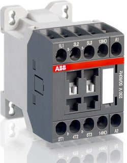
Ordering
1 piece
85364900
Popular Downloads
Dimensions
45 mm
72.5 mm
68 mm
0.22 kg
Technical
3
0
1
0
IEC 60947-1 / 60947-4-1 and EN 60947-1 / 60947-4-1, UL 508, CSA C22.2 N°14
Auxiliary Circuit 690 V
Main Circuit 690 V
Auxiliary Circuit 690 V
Main Circuit 690 V
Auxiliary Circuit 50 / 60 Hz
Main Circuit 50 / 60 Hz
Auxiliary Circuit 50 / 60 Hz
Main Circuit 50 / 60 Hz
acc. to IEC 60947-4-1, Open Contactors Θ = 40 °C 25 A
acc. to IEC 60947-5-1, Θ = 40 °C 10 A
acc. to IEC 60947-4-1, Open Contactors Θ = 40 °C 25 A
acc. to IEC 60947-5-1, Θ = 40 °C 10 A
(690 V) 40 °C 24 A
(690 V) 60 °C 20 A
(690 V) 70 °C 16 A
(690 V) 40 °C 24 A
(690 V) 60 °C 20 A
(690 V) 70 °C 16 A
(415 V) 60 °C 15.5 A
(440 V) 60 °C 13.6 A
(500 V) 60 °C 12.5 A
(690 V) 60 °C 9 A
(380 / 400 V) 60 °C 15.5 A
(220 / 230 / 240 V) 60 °C 15.7 A
(415 V) 60 °C 15.5 A
(440 V) 60 °C 13.6 A
(500 V) 60 °C 12.5 A
(690 V) 60 °C 9 A
(380 / 400 V) 60 °C 15.5 A
(220 / 230 / 240 V) 60 °C 15.7 A
(500 V) NC 2
(500 V) 2 A
(690 V) 2 A
(24 / 127 V) 6 A
(220 / 240 V) 4 A
(400 / 440 V) 3 A
(500 V) NC 2
(500 V) 2 A
(690 V) 2 A
(24 / 127 V) 6 A
(220 / 240 V) 4 A
(400 / 440 V) 3 A
(24 V) 6 A / 144 W
(48 V) 2.8 A / 134 W
(72 V) 1 A / 72 W
(110 V) 0.55 A / 60 W
(125 V) 0.55 A / 69 W
(220 V) 0.27 A / 60 W
(250 V) 0.27 A / 68 W
(24 V) 6 A / 144 W
(48 V) 2.8 A / 134 W
(72 V) 1 A / 72 W
(110 V) 0.55 A / 60 W
(125 V) 0.55 A / 69 W
(220 V) 0.27 A / 60 W
(250 V) 0.27 A / 68 W
(400 V) 7.5 kW
(415 V) 7.5 kW
(440 V) 7.5 kW
(500 V) 7.5 kW
(690 V) 7.5 kW
(220 / 230 / 240 V) 4 kW
(400 V) 7.5 kW
(415 V) 7.5 kW
(440 V) 7.5 kW
(500 V) 7.5 kW
(690 V) 7.5 kW
(220 / 230 / 240 V) 4 kW
at 40 °C Ambient Temp, in Free Air, from a Cold State 10 s 124 A
at 40 °C Ambient Temp, in Free Air, from a Cold State 15 min 24 A
at 40 °C Ambient Temp, in Free Air, from a Cold State 1 min 55 A
at 40 °C Ambient Temp, in Free Air, from a Cold State 1 s 250 A
at 40 °C Ambient Temp, in Free Air, from a Cold State 30 s 75 A
for 0.1 s 140 A
for 1 s 100 A
at 40 °C Ambient Temp, in Free Air, from a Cold State 10 s 124 A
at 40 °C Ambient Temp, in Free Air, from a Cold State 15 min 24 A
at 40 °C Ambient Temp, in Free Air, from a Cold State 1 min 55 A
at 40 °C Ambient Temp, in Free Air, from a Cold State 1 s 250 A
at 40 °C Ambient Temp, in Free Air, from a Cold State 30 s 75 A
for 0.1 s 140 A
for 1 s 100 A
cos phi=0.45 (cos phi=0.35 for Ie > 100 A) at 440 V 155 A
cos phi=0.45 (cos phi=0.35 for Ie > 100 A) at 690 V 90 A
cos phi=0.45 (cos phi=0.35 for Ie > 100 A) at 440 V 155 A
cos phi=0.45 (cos phi=0.35 for Ie > 100 A) at 690 V 90 A
acc. to IEC 60947-4-1 and VDE 0110 (Gr. C) 690 V
acc. to IEC 60947-5-1 and VDE 0110 (Gr. C) 690 V
acc. to UL/CSA 600 V
acc. to IEC 60947-4-1 and VDE 0110 (Gr. C) 690 V
acc. to IEC 60947-5-1 and VDE 0110 (Gr. C) 690 V
acc. to UL/CSA 600 V
Auxiliary Circuit 6 kV
(AC-1) 600 cycles per hour
(AC-15) 1200 cycles per hour
(AC-2 / AC-4) 300 cycles per hour
(AC-3) 1200 cycles per hour
(DC-13) 900 cycles per hour
(AC-1) 600 cycles per hour
(AC-15) 1200 cycles per hour
(AC-2 / AC-4) 300 cycles per hour
(AC-3) 1200 cycles per hour
(DC-13) 900 cycles per hour
3600 cycles per hour
50 Hz 24 V
60 Hz 24 V
50 Hz 24 V
60 Hz 24 V
at Rated Operating Conditions AC-1 per Pole 1.2 W
at Rated Operating Conditions AC-3 per Pole 0.5 W
at Rated Operating Conditions AC-1 per Pole 1.2 W
at Rated Operating Conditions AC-3 per Pole 0.5 W
Between Coil De-energization and NC Contact Closing 7 ... 22 ms
Between Coil De-energization and NO Contact Opening 5 ... 19 ms
Between Coil Energization and NC Contact Opening 6 ... 18 ms
Between Coil Energization and NO Contact Closing 9 ... 24 ms
Between Coil De-energization and NC Contact Closing 7 ... 22 ms
Between Coil De-energization and NO Contact Opening 5 ... 19 ms
Between Coil Energization and NC Contact Opening 6 ... 18 ms
Between Coil Energization and NO Contact Closing 9 ... 24 ms
Flexible with Ferrule 1/2x 0.75 ... 2.5 mm²
Flexible with Insulated Ferrule 1x 0.75 ... 2.5 mm²
Flexible with Insulated Ferrule 2x 0.75 ... 1.5 mm²
Rigid 1/2x 0.75 ... 4 mm²
Flexible with Ferrule 1/2x 0.75 ... 2.5 mm²
Flexible with Insulated Ferrule 1x 0.75 ... 2.5 mm²
Flexible with Insulated Ferrule 2x 0.75 ... 1.5 mm²
Rigid 1/2x 0.75 ... 4 mm²
Flexible with Ferrule 1/2x 0.75 ... 2.5 mm²
Flexible with Insulated Ferrule 1x 0.75 ... 2.5 mm²
Flexible with Insulated Ferrule 2x 0.75 ... 1.5 mm²
Rigid 1/2x 0.75 ... 2.5 mm²
Flexible with Ferrule 1/2x 0.75 ... 2.5 mm²
Flexible with Insulated Ferrule 1x 0.75 ... 2.5 mm²
Flexible with Insulated Ferrule 2x 0.75 ... 1.5 mm²
Rigid 1/2x 0.75 ... 2.5 mm²
Flexible with Ferrule 1/2x 0.75 ... 2.5 mm²
Flexible with Insulated Ferrule 1x 0.75 ... 2.5 mm²
Flexible with Insulated Ferrule 2x 0.75 ... 1.5 mm²
Rigid 1/2x 0.75 ... 2.5 mm²
Flexible with Ferrule 1/2x 0.75 ... 2.5 mm²
Flexible with Insulated Ferrule 1x 0.75 ... 2.5 mm²
Flexible with Insulated Ferrule 2x 0.75 ... 1.5 mm²
Rigid 1/2x 0.75 ... 2.5 mm²
Auxiliary Circuit 9 mm
Control Circuit 9 mm
Main Circuit 9 mm
Auxiliary Circuit 9 mm
Control Circuit 9 mm
Main Circuit 9 mm
acc. to IEC 60529, IEC 60947-1, EN 60529 Auxiliary Terminals IP20
acc. to IEC 60529, IEC 60947-1, EN 60529 Coil Terminals IP20
acc. to IEC 60529, IEC 60947-1, EN 60529 Main Terminals IP20
acc. to IEC 60529, IEC 60947-1, EN 60529 Auxiliary Terminals IP20
acc. to IEC 60529, IEC 60947-1, EN 60529 Coil Terminals IP20
acc. to IEC 60529, IEC 60947-1, EN 60529 Main Terminals IP20
Auxiliary Circuit 1 N·m
Control Circuit 1 N·m
Main Circuit 1 N·m
Auxiliary Circuit 1 N·m
Control Circuit 1 N·m
Main Circuit 1 N·m
Screw Terminals
Block Contactor
Technical UL/CSA
(600 V AC) 20 A
(120 V AC) Single Phase 3/4 hp
(200 ... 208 V AC) Three Phase 3 hp
(220 ... 240 V AC) Three Phase 5 hp
(240 V AC) Single Phase 2 hp
(440 ... 480 V AC) Three Phase 10 hp
(550 ... 600 V AC) Three Phase 10 hp
(120 V AC) Single Phase 3/4 hp
(200 ... 208 V AC) Three Phase 3 hp
(220 ... 240 V AC) Three Phase 5 hp
(240 V AC) Single Phase 2 hp
(440 ... 480 V AC) Three Phase 10 hp
(550 ... 600 V AC) Three Phase 10 hp
Auxiliary Circuit 9 in·lb
Control Circuit 9 in·lb
Main Circuit 9 in·lb
Auxiliary Circuit 9 in·lb
Control Circuit 9 in·lb
Main Circuit 9 in·lb
(120 V AC) Single Phase 13.8 A
(200 ... 208 V AC) Three Phase 11 A
(220 ... 240 V AC) Three Phase 15.2 A
(240 V AC) Single Phase 12 A
(440 ... 480 V AC) Three Phase 14 A
(550 ... 600 V AC) Three Phase 11 A
(120 V AC) Single Phase 13.8 A
(200 ... 208 V AC) Three Phase 11 A
(220 ... 240 V AC) Three Phase 15.2 A
(240 V AC) Single Phase 12 A
(440 ... 480 V AC) Three Phase 14 A
(550 ... 600 V AC) Three Phase 11 A
Environmental
Close to Contactor Fitted with Thermal O/L Relay -25 ... 60 °C
Close to Contactor without Thermal O/L Relay -40 ... 70 °C
Close to Contactor for Storage -60 ... +80 °C
Close to Contactor Fitted with Thermal O/L Relay -25 ... 60 °C
Close to Contactor without Thermal O/L Relay -40 ... 70 °C
Close to Contactor for Storage -60 ... +80 °C
Category B according to IEC 60947-1 Annex Q
Without Derating 3000 m
Closed, Shock Direction: B1 10 g
Closed, Shock Direction: C1 20 g
Closed, Shock Direction: C2 20 g
Open, Shock Direction: B1 5 g
Open, Shock Direction: C1 9 g
Open, Shock Direction: C2 14 g
Shock Direction: A 20 g
Shock Direction: B2 15 g
Closed, Shock Direction: B1 10 g
Closed, Shock Direction: C1 20 g
Closed, Shock Direction: C2 20 g
Open, Shock Direction: B1 5 g
Open, Shock Direction: C1 9 g
Open, Shock Direction: C2 14 g
Shock Direction: A 20 g
Shock Direction: B2 15 g
3g Closed Position & 2g Open Position 5 ... 300 Hz
Material Compliance
Following EU Directive 2011/65/EU and Amendment 2015/863 July 22, 2019
Business To Business
5. Small Equipment (No External Dimension More Than 50 cm)
Certificates and Declarations
Container Information
box 1 piece
78 mm
80 mm
48 mm
0.22 kg
3471523036208
960 piece
External Classifications and Standards
Q
EC000066 - Power contactor, AC switching
EC000066 - Power contactor, AC switching
EC000066 - Power contactor, AC switching
V11.0 : 27371003
39121529
4761 >> Magnet contactor, AC-switching
3210514

Ordering
1 piece
85364900
Popular Downloads
Dimensions
45 mm
72.5 mm
68 mm
0.22 kg
Technical
3
0
0
1
IEC 60947-1 / 60947-4-1 and EN 60947-1 / 60947-4-1, UL 508, CSA C22.2 N°14
Auxiliary Circuit 690 V
Main Circuit 690 V
Auxiliary Circuit 690 V
Main Circuit 690 V
Auxiliary Circuit 50 / 60 Hz
Main Circuit 50 / 60 Hz
Auxiliary Circuit 50 / 60 Hz
Main Circuit 50 / 60 Hz
acc. to IEC 60947-4-1, Open Contactors Θ = 40 °C 25 A
acc. to IEC 60947-5-1, Θ = 40 °C 10 A
acc. to IEC 60947-4-1, Open Contactors Θ = 40 °C 25 A
acc. to IEC 60947-5-1, Θ = 40 °C 10 A
(690 V) 40 °C 24 A
(690 V) 60 °C 20 A
(690 V) 70 °C 16 A
(690 V) 40 °C 24 A
(690 V) 60 °C 20 A
(690 V) 70 °C 16 A
(415 V) 60 °C 15.5 A
(440 V) 60 °C 13.6 A
(500 V) 60 °C 12.5 A
(690 V) 60 °C 9 A
(380 / 400 V) 60 °C 15.5 A
(220 / 230 / 240 V) 60 °C 15.7 A
(415 V) 60 °C 15.5 A
(440 V) 60 °C 13.6 A
(500 V) 60 °C 12.5 A
(690 V) 60 °C 9 A
(380 / 400 V) 60 °C 15.5 A
(220 / 230 / 240 V) 60 °C 15.7 A
(500 V) NC 2
(500 V) 2 A
(690 V) 2 A
(24 / 127 V) 6 A
(220 / 240 V) 4 A
(400 / 440 V) 3 A
(500 V) NC 2
(500 V) 2 A
(690 V) 2 A
(24 / 127 V) 6 A
(220 / 240 V) 4 A
(400 / 440 V) 3 A
(24 V) 6 A / 144 W
(48 V) 2.8 A / 134 W
(72 V) 1 A / 72 W
(110 V) 0.55 A / 60 W
(125 V) 0.55 A / 69 W
(220 V) 0.27 A / 60 W
(250 V) 0.27 A / 68 W
(24 V) 6 A / 144 W
(48 V) 2.8 A / 134 W
(72 V) 1 A / 72 W
(110 V) 0.55 A / 60 W
(125 V) 0.55 A / 69 W
(220 V) 0.27 A / 60 W
(250 V) 0.27 A / 68 W
(400 V) 7.5 kW
(415 V) 7.5 kW
(440 V) 7.5 kW
(500 V) 7.5 kW
(690 V) 7.5 kW
(220 / 230 / 240 V) 4 kW
(400 V) 7.5 kW
(415 V) 7.5 kW
(440 V) 7.5 kW
(500 V) 7.5 kW
(690 V) 7.5 kW
(220 / 230 / 240 V) 4 kW
at 40 °C Ambient Temp, in Free Air, from a Cold State 10 s 124 A
at 40 °C Ambient Temp, in Free Air, from a Cold State 15 min 24 A
at 40 °C Ambient Temp, in Free Air, from a Cold State 1 min 55 A
at 40 °C Ambient Temp, in Free Air, from a Cold State 1 s 250 A
at 40 °C Ambient Temp, in Free Air, from a Cold State 30 s 75 A
for 0.1 s 140 A
for 1 s 100 A
at 40 °C Ambient Temp, in Free Air, from a Cold State 10 s 124 A
at 40 °C Ambient Temp, in Free Air, from a Cold State 15 min 24 A
at 40 °C Ambient Temp, in Free Air, from a Cold State 1 min 55 A
at 40 °C Ambient Temp, in Free Air, from a Cold State 1 s 250 A
at 40 °C Ambient Temp, in Free Air, from a Cold State 30 s 75 A
for 0.1 s 140 A
for 1 s 100 A
cos phi=0.45 (cos phi=0.35 for Ie > 100 A) at 440 V 155 A
cos phi=0.45 (cos phi=0.35 for Ie > 100 A) at 690 V 90 A
cos phi=0.45 (cos phi=0.35 for Ie > 100 A) at 440 V 155 A
cos phi=0.45 (cos phi=0.35 for Ie > 100 A) at 690 V 90 A
acc. to IEC 60947-4-1 and VDE 0110 (Gr. C) 690 V
acc. to IEC 60947-5-1 and VDE 0110 (Gr. C) 690 V
acc. to UL/CSA 600 V
acc. to IEC 60947-4-1 and VDE 0110 (Gr. C) 690 V
acc. to IEC 60947-5-1 and VDE 0110 (Gr. C) 690 V
acc. to UL/CSA 600 V
Auxiliary Circuit 6 kV
(AC-1) 600 cycles per hour
(AC-15) 1200 cycles per hour
(AC-2 / AC-4) 300 cycles per hour
(AC-3) 1200 cycles per hour
(DC-13) 900 cycles per hour
(AC-1) 600 cycles per hour
(AC-15) 1200 cycles per hour
(AC-2 / AC-4) 300 cycles per hour
(AC-3) 1200 cycles per hour
(DC-13) 900 cycles per hour
3600 cycles per hour
50 Hz 230 V
60 Hz 230 V
50 Hz 230 V
60 Hz 230 V
at Rated Operating Conditions AC-1 per Pole 1.2 W
at Rated Operating Conditions AC-3 per Pole 0.5 W
at Rated Operating Conditions AC-1 per Pole 1.2 W
at Rated Operating Conditions AC-3 per Pole 0.5 W
Between Coil De-energization and NC Contact Closing 7 ... 22 ms
Between Coil De-energization and NO Contact Opening 5 ... 19 ms
Between Coil Energization and NC Contact Opening 6 ... 18 ms
Between Coil Energization and NO Contact Closing 9 ... 24 ms
Between Coil De-energization and NC Contact Closing 7 ... 22 ms
Between Coil De-energization and NO Contact Opening 5 ... 19 ms
Between Coil Energization and NC Contact Opening 6 ... 18 ms
Between Coil Energization and NO Contact Closing 9 ... 24 ms
Flexible with Ferrule 1/2x 0.75 ... 2.5 mm²
Flexible with Insulated Ferrule 1x 0.75 ... 2.5 mm²
Flexible with Insulated Ferrule 2x 0.75 ... 1.5 mm²
Rigid 1/2x 0.75 ... 4 mm²
Flexible with Ferrule 1/2x 0.75 ... 2.5 mm²
Flexible with Insulated Ferrule 1x 0.75 ... 2.5 mm²
Flexible with Insulated Ferrule 2x 0.75 ... 1.5 mm²
Rigid 1/2x 0.75 ... 4 mm²
Flexible with Ferrule 1/2x 0.75 ... 2.5 mm²
Flexible with Insulated Ferrule 1x 0.75 ... 2.5 mm²
Flexible with Insulated Ferrule 2x 0.75 ... 1.5 mm²
Rigid 1/2x 0.75 ... 2.5 mm²
Flexible with Ferrule 1/2x 0.75 ... 2.5 mm²
Flexible with Insulated Ferrule 1x 0.75 ... 2.5 mm²
Flexible with Insulated Ferrule 2x 0.75 ... 1.5 mm²
Rigid 1/2x 0.75 ... 2.5 mm²
Flexible with Ferrule 1/2x 0.75 ... 2.5 mm²
Flexible with Insulated Ferrule 1x 0.75 ... 2.5 mm²
Flexible with Insulated Ferrule 2x 0.75 ... 1.5 mm²
Rigid 1/2x 0.75 ... 2.5 mm²
Flexible with Ferrule 1/2x 0.75 ... 2.5 mm²
Flexible with Insulated Ferrule 1x 0.75 ... 2.5 mm²
Flexible with Insulated Ferrule 2x 0.75 ... 1.5 mm²
Rigid 1/2x 0.75 ... 2.5 mm²
Auxiliary Circuit 9 mm
Control Circuit 9 mm
Main Circuit 9 mm
Auxiliary Circuit 9 mm
Control Circuit 9 mm
Main Circuit 9 mm
acc. to IEC 60529, IEC 60947-1, EN 60529 Auxiliary Terminals IP20
acc. to IEC 60529, IEC 60947-1, EN 60529 Coil Terminals IP20
acc. to IEC 60529, IEC 60947-1, EN 60529 Main Terminals IP20
acc. to IEC 60529, IEC 60947-1, EN 60529 Auxiliary Terminals IP20
acc. to IEC 60529, IEC 60947-1, EN 60529 Coil Terminals IP20
acc. to IEC 60529, IEC 60947-1, EN 60529 Main Terminals IP20
Auxiliary Circuit 1 N·m
Control Circuit 1 N·m
Main Circuit 1 N·m
Auxiliary Circuit 1 N·m
Control Circuit 1 N·m
Main Circuit 1 N·m
Screw Terminals
Block Contactor
Technical UL/CSA
(600 V AC) 20 A
(120 V AC) Single Phase 3/4 hp
(200 ... 208 V AC) Three Phase 3 hp
(220 ... 240 V AC) Three Phase 5 hp
(240 V AC) Single Phase 2 hp
(440 ... 480 V AC) Three Phase 10 hp
(550 ... 600 V AC) Three Phase 10 hp
(120 V AC) Single Phase 3/4 hp
(200 ... 208 V AC) Three Phase 3 hp
(220 ... 240 V AC) Three Phase 5 hp
(240 V AC) Single Phase 2 hp
(440 ... 480 V AC) Three Phase 10 hp
(550 ... 600 V AC) Three Phase 10 hp
Auxiliary Circuit 9 in·lb
Control Circuit 9 in·lb
Main Circuit 9 in·lb
Auxiliary Circuit 9 in·lb
Control Circuit 9 in·lb
Main Circuit 9 in·lb
(120 V AC) Single Phase 13.8 A
(200 ... 208 V AC) Three Phase 11 A
(220 ... 240 V AC) Three Phase 15.2 A
(240 V AC) Single Phase 12 A
(440 ... 480 V AC) Three Phase 14 A
(550 ... 600 V AC) Three Phase 11 A
(120 V AC) Single Phase 13.8 A
(200 ... 208 V AC) Three Phase 11 A
(220 ... 240 V AC) Three Phase 15.2 A
(240 V AC) Single Phase 12 A
(440 ... 480 V AC) Three Phase 14 A
(550 ... 600 V AC) Three Phase 11 A
Environmental
Close to Contactor Fitted with Thermal O/L Relay -25 ... 60 °C
Close to Contactor without Thermal O/L Relay -40 ... 70 °C
Close to Contactor for Storage -60 ... +80 °C
Close to Contactor Fitted with Thermal O/L Relay -25 ... 60 °C
Close to Contactor without Thermal O/L Relay -40 ... 70 °C
Close to Contactor for Storage -60 ... +80 °C
Category B according to IEC 60947-1 Annex Q
Without Derating 3000 m
Closed, Shock Direction: B1 10 g
Closed, Shock Direction: C1 20 g
Closed, Shock Direction: C2 20 g
Open, Shock Direction: B1 5 g
Open, Shock Direction: C1 9 g
Open, Shock Direction: C2 14 g
Shock Direction: A 20 g
Shock Direction: B2 15 g
Closed, Shock Direction: B1 10 g
Closed, Shock Direction: C1 20 g
Closed, Shock Direction: C2 20 g
Open, Shock Direction: B1 5 g
Open, Shock Direction: C1 9 g
Open, Shock Direction: C2 14 g
Shock Direction: A 20 g
Shock Direction: B2 15 g
3g Closed Position & 2g Open Position 5 ... 300 Hz
Material Compliance
Following EU Directive 2011/65/EU and Amendment 2015/863 July 22, 2019
Business To Business
5. Small Equipment (No External Dimension More Than 50 cm)
Certificates and Declarations
Container Information
box 1 piece
78 mm
80 mm
48 mm
0.22 kg
3471523037267
960 piece
External Classifications and Standards
Q
EC000066 - Power contactor, AC switching
EC000066 - Power contactor, AC switching
EC000066 - Power contactor, AC switching
V11.0 : 27371003
39121529
4761 >> Magnet contactor, AC-switching
3210517

Ordering
1 piece
85364900
Popular Downloads
Dimensions
45 mm
72.5 mm
68 mm
0.22 kg
Technical
3
0
1
0
IEC 60947-1 / 60947-4-1 and EN 60947-1 / 60947-4-1, UL 508, CSA C22.2 N°14
Auxiliary Circuit 690 V
Main Circuit 690 V
Auxiliary Circuit 690 V
Main Circuit 690 V
Auxiliary Circuit 50 / 60 Hz
Main Circuit 50 / 60 Hz
Auxiliary Circuit 50 / 60 Hz
Main Circuit 50 / 60 Hz
acc. to IEC 60947-4-1, Open Contactors Θ = 40 °C 25 A
acc. to IEC 60947-5-1, Θ = 40 °C 10 A
acc. to IEC 60947-4-1, Open Contactors Θ = 40 °C 25 A
acc. to IEC 60947-5-1, Θ = 40 °C 10 A
(690 V) 40 °C 24 A
(690 V) 60 °C 20 A
(690 V) 70 °C 16 A
(690 V) 40 °C 24 A
(690 V) 60 °C 20 A
(690 V) 70 °C 16 A
(415 V) 60 °C 15.5 A
(440 V) 60 °C 13.6 A
(500 V) 60 °C 12.5 A
(690 V) 60 °C 9 A
(380 / 400 V) 60 °C 15.5 A
(220 / 230 / 240 V) 60 °C 15.7 A
(415 V) 60 °C 15.5 A
(440 V) 60 °C 13.6 A
(500 V) 60 °C 12.5 A
(690 V) 60 °C 9 A
(380 / 400 V) 60 °C 15.5 A
(220 / 230 / 240 V) 60 °C 15.7 A
(500 V) NC 2
(500 V) 2 A
(690 V) 2 A
(24 / 127 V) 6 A
(220 / 240 V) 4 A
(400 / 440 V) 3 A
(500 V) NC 2
(500 V) 2 A
(690 V) 2 A
(24 / 127 V) 6 A
(220 / 240 V) 4 A
(400 / 440 V) 3 A
(24 V) 6 A / 144 W
(48 V) 2.8 A / 134 W
(72 V) 1 A / 72 W
(110 V) 0.55 A / 60 W
(125 V) 0.55 A / 69 W
(220 V) 0.27 A / 60 W
(250 V) 0.27 A / 68 W
(24 V) 6 A / 144 W
(48 V) 2.8 A / 134 W
(72 V) 1 A / 72 W
(110 V) 0.55 A / 60 W
(125 V) 0.55 A / 69 W
(220 V) 0.27 A / 60 W
(250 V) 0.27 A / 68 W
(400 V) 7.5 kW
(415 V) 7.5 kW
(440 V) 7.5 kW
(500 V) 7.5 kW
(690 V) 7.5 kW
(220 / 230 / 240 V) 4 kW
(400 V) 7.5 kW
(415 V) 7.5 kW
(440 V) 7.5 kW
(500 V) 7.5 kW
(690 V) 7.5 kW
(220 / 230 / 240 V) 4 kW
at 40 °C Ambient Temp, in Free Air, from a Cold State 10 s 124 A
at 40 °C Ambient Temp, in Free Air, from a Cold State 15 min 24 A
at 40 °C Ambient Temp, in Free Air, from a Cold State 1 min 55 A
at 40 °C Ambient Temp, in Free Air, from a Cold State 1 s 250 A
at 40 °C Ambient Temp, in Free Air, from a Cold State 30 s 75 A
for 0.1 s 140 A
for 1 s 100 A
at 40 °C Ambient Temp, in Free Air, from a Cold State 10 s 124 A
at 40 °C Ambient Temp, in Free Air, from a Cold State 15 min 24 A
at 40 °C Ambient Temp, in Free Air, from a Cold State 1 min 55 A
at 40 °C Ambient Temp, in Free Air, from a Cold State 1 s 250 A
at 40 °C Ambient Temp, in Free Air, from a Cold State 30 s 75 A
for 0.1 s 140 A
for 1 s 100 A
cos phi=0.45 (cos phi=0.35 for Ie > 100 A) at 440 V 155 A
cos phi=0.45 (cos phi=0.35 for Ie > 100 A) at 690 V 90 A
cos phi=0.45 (cos phi=0.35 for Ie > 100 A) at 440 V 155 A
cos phi=0.45 (cos phi=0.35 for Ie > 100 A) at 690 V 90 A
acc. to IEC 60947-4-1 and VDE 0110 (Gr. C) 690 V
acc. to IEC 60947-5-1 and VDE 0110 (Gr. C) 690 V
acc. to UL/CSA 600 V
acc. to IEC 60947-4-1 and VDE 0110 (Gr. C) 690 V
acc. to IEC 60947-5-1 and VDE 0110 (Gr. C) 690 V
acc. to UL/CSA 600 V
Auxiliary Circuit 6 kV
(AC-1) 600 cycles per hour
(AC-15) 1200 cycles per hour
(AC-2 / AC-4) 300 cycles per hour
(AC-3) 1200 cycles per hour
(DC-13) 900 cycles per hour
(AC-1) 600 cycles per hour
(AC-15) 1200 cycles per hour
(AC-2 / AC-4) 300 cycles per hour
(AC-3) 1200 cycles per hour
(DC-13) 900 cycles per hour
3600 cycles per hour
50 Hz 230 V
60 Hz 230 V
50 Hz 230 V
60 Hz 230 V
at Rated Operating Conditions AC-1 per Pole 1.2 W
at Rated Operating Conditions AC-3 per Pole 0.5 W
at Rated Operating Conditions AC-1 per Pole 1.2 W
at Rated Operating Conditions AC-3 per Pole 0.5 W
Between Coil De-energization and NC Contact Closing 7 ... 22 ms
Between Coil De-energization and NO Contact Opening 5 ... 19 ms
Between Coil Energization and NC Contact Opening 6 ... 18 ms
Between Coil Energization and NO Contact Closing 9 ... 24 ms
Between Coil De-energization and NC Contact Closing 7 ... 22 ms
Between Coil De-energization and NO Contact Opening 5 ... 19 ms
Between Coil Energization and NC Contact Opening 6 ... 18 ms
Between Coil Energization and NO Contact Closing 9 ... 24 ms
Flexible with Ferrule 1/2x 0.75 ... 2.5 mm²
Flexible with Insulated Ferrule 1x 0.75 ... 2.5 mm²
Flexible with Insulated Ferrule 2x 0.75 ... 1.5 mm²
Rigid 1/2x 0.75 ... 4 mm²
Flexible with Ferrule 1/2x 0.75 ... 2.5 mm²
Flexible with Insulated Ferrule 1x 0.75 ... 2.5 mm²
Flexible with Insulated Ferrule 2x 0.75 ... 1.5 mm²
Rigid 1/2x 0.75 ... 4 mm²
Flexible with Ferrule 1/2x 0.75 ... 2.5 mm²
Flexible with Insulated Ferrule 1x 0.75 ... 2.5 mm²
Flexible with Insulated Ferrule 2x 0.75 ... 1.5 mm²
Rigid 1/2x 0.75 ... 2.5 mm²
Flexible with Ferrule 1/2x 0.75 ... 2.5 mm²
Flexible with Insulated Ferrule 1x 0.75 ... 2.5 mm²
Flexible with Insulated Ferrule 2x 0.75 ... 1.5 mm²
Rigid 1/2x 0.75 ... 2.5 mm²
Flexible with Ferrule 1/2x 0.75 ... 2.5 mm²
Flexible with Insulated Ferrule 1x 0.75 ... 2.5 mm²
Flexible with Insulated Ferrule 2x 0.75 ... 1.5 mm²
Rigid 1/2x 0.75 ... 2.5 mm²
Flexible with Ferrule 1/2x 0.75 ... 2.5 mm²
Flexible with Insulated Ferrule 1x 0.75 ... 2.5 mm²
Flexible with Insulated Ferrule 2x 0.75 ... 1.5 mm²
Rigid 1/2x 0.75 ... 2.5 mm²
Auxiliary Circuit 9 mm
Control Circuit 9 mm
Main Circuit 9 mm
Auxiliary Circuit 9 mm
Control Circuit 9 mm
Main Circuit 9 mm
acc. to IEC 60529, IEC 60947-1, EN 60529 Auxiliary Terminals IP20
acc. to IEC 60529, IEC 60947-1, EN 60529 Coil Terminals IP20
acc. to IEC 60529, IEC 60947-1, EN 60529 Main Terminals IP20
acc. to IEC 60529, IEC 60947-1, EN 60529 Auxiliary Terminals IP20
acc. to IEC 60529, IEC 60947-1, EN 60529 Coil Terminals IP20
acc. to IEC 60529, IEC 60947-1, EN 60529 Main Terminals IP20
Auxiliary Circuit 1 N·m
Control Circuit 1 N·m
Main Circuit 1 N·m
Auxiliary Circuit 1 N·m
Control Circuit 1 N·m
Main Circuit 1 N·m
Screw Terminals
Block Contactor
Technical UL/CSA
(600 V AC) 20 A
(120 V AC) Single Phase 3/4 hp
(200 ... 208 V AC) Three Phase 3 hp
(220 ... 240 V AC) Three Phase 5 hp
(240 V AC) Single Phase 2 hp
(440 ... 480 V AC) Three Phase 10 hp
(550 ... 600 V AC) Three Phase 10 hp
(120 V AC) Single Phase 3/4 hp
(200 ... 208 V AC) Three Phase 3 hp
(220 ... 240 V AC) Three Phase 5 hp
(240 V AC) Single Phase 2 hp
(440 ... 480 V AC) Three Phase 10 hp
(550 ... 600 V AC) Three Phase 10 hp
Auxiliary Circuit 9 in·lb
Control Circuit 9 in·lb
Main Circuit 9 in·lb
Auxiliary Circuit 9 in·lb
Control Circuit 9 in·lb
Main Circuit 9 in·lb
(120 V AC) Single Phase 13.8 A
(200 ... 208 V AC) Three Phase 11 A
(220 ... 240 V AC) Three Phase 15.2 A
(240 V AC) Single Phase 12 A
(440 ... 480 V AC) Three Phase 14 A
(550 ... 600 V AC) Three Phase 11 A
(120 V AC) Single Phase 13.8 A
(200 ... 208 V AC) Three Phase 11 A
(220 ... 240 V AC) Three Phase 15.2 A
(240 V AC) Single Phase 12 A
(440 ... 480 V AC) Three Phase 14 A
(550 ... 600 V AC) Three Phase 11 A
Environmental
Close to Contactor Fitted with Thermal O/L Relay -25 ... 60 °C
Close to Contactor without Thermal O/L Relay -40 ... 70 °C
Close to Contactor for Storage -60 ... +80 °C
Close to Contactor Fitted with Thermal O/L Relay -25 ... 60 °C
Close to Contactor without Thermal O/L Relay -40 ... 70 °C
Close to Contactor for Storage -60 ... +80 °C
Category B according to IEC 60947-1 Annex Q
Without Derating 3000 m
Closed, Shock Direction: B1 10 g
Closed, Shock Direction: C1 20 g
Closed, Shock Direction: C2 20 g
Open, Shock Direction: B1 5 g
Open, Shock Direction: C1 9 g
Open, Shock Direction: C2 14 g
Shock Direction: A 20 g
Shock Direction: B2 15 g
Closed, Shock Direction: B1 10 g
Closed, Shock Direction: C1 20 g
Closed, Shock Direction: C2 20 g
Open, Shock Direction: B1 5 g
Open, Shock Direction: C1 9 g
Open, Shock Direction: C2 14 g
Shock Direction: A 20 g
Shock Direction: B2 15 g
3g Closed Position & 2g Open Position 5 ... 300 Hz
Material Compliance
Following EU Directive 2011/65/EU and Amendment 2015/863 July 22, 2019
Business To Business
5. Small Equipment (No External Dimension More Than 50 cm)
Certificates and Declarations
Container Information
box 1 piece
78 mm
80 mm
48 mm
0.22 kg
3471523036260
960 piece
External Classifications and Standards
Q
EC000066 - Power contactor, AC switching
EC000066 - Power contactor, AC switching
EC000066 - Power contactor, AC switching
V11.0 : 27371003
39121529
4761 >> Magnet contactor, AC-switching
3210516

AS16-30-01-28 400V50/60HZ Contactor

Ordering
1 piece
85364900
Popular Downloads
Dimensions
45 mm
72.5 mm
68 mm
0.28 kg
Technical
3
0
1
0
IEC 60947-1 / 60947-4-1 and EN 60947-1 / 60947-4-1, UL 508, CSA C22.2 N°14
Auxiliary Circuit 690 V
Main Circuit 690 V
Auxiliary Circuit 690 V
Main Circuit 690 V
Auxiliary Circuit 50 / 60 Hz
Main Circuit 50 / 60 Hz
Auxiliary Circuit 50 / 60 Hz
Main Circuit 50 / 60 Hz
acc. to IEC 60947-4-1, Open Contactors Θ = 40 °C 25 A
acc. to IEC 60947-5-1, Θ = 40 °C 10 A
acc. to IEC 60947-4-1, Open Contactors Θ = 40 °C 25 A
acc. to IEC 60947-5-1, Θ = 40 °C 10 A
(690 V) 40 °C 24 A
(690 V) 60 °C 20 A
(690 V) 70 °C 16 A
(690 V) 40 °C 24 A
(690 V) 60 °C 20 A
(690 V) 70 °C 16 A
(415 V) 60 °C 15.5 A
(440 V) 60 °C 13.6 A
(500 V) 60 °C 12.5 A
(690 V) 60 °C 9 A
(380 / 400 V) 60 °C 15.5 A
(220 / 230 / 240 V) 60 °C 15.7 A
(415 V) 60 °C 15.5 A
(440 V) 60 °C 13.6 A
(500 V) 60 °C 12.5 A
(690 V) 60 °C 9 A
(380 / 400 V) 60 °C 15.5 A
(220 / 230 / 240 V) 60 °C 15.7 A
(500 V) NC 2
(500 V) 2 A
(690 V) 2 A
(24 / 127 V) 6 A
(220 / 240 V) 4 A
(400 / 440 V) 3 A
(500 V) NC 2
(500 V) 2 A
(690 V) 2 A
(24 / 127 V) 6 A
(220 / 240 V) 4 A
(400 / 440 V) 3 A
(24 V) 6 A / 144 W
(48 V) 2.8 A / 134 W
(72 V) 1 A / 72 W
(110 V) 0.55 A / 60 W
(125 V) 0.55 A / 69 W
(220 V) 0.27 A / 60 W
(250 V) 0.27 A / 68 W
(24 V) 6 A / 144 W
(48 V) 2.8 A / 134 W
(72 V) 1 A / 72 W
(110 V) 0.55 A / 60 W
(125 V) 0.55 A / 69 W
(220 V) 0.27 A / 60 W
(250 V) 0.27 A / 68 W
(400 V) 7.5 kW
(415 V) 7.5 kW
(440 V) 7.5 kW
(500 V) 7.5 kW
(690 V) 7.5 kW
(220 / 230 / 240 V) 4 kW
(400 V) 7.5 kW
(415 V) 7.5 kW
(440 V) 7.5 kW
(500 V) 7.5 kW
(690 V) 7.5 kW
(220 / 230 / 240 V) 4 kW
at 40 °C Ambient Temp, in Free Air, from a Cold State 10 s 124 A
at 40 °C Ambient Temp, in Free Air, from a Cold State 15 min 24 A
at 40 °C Ambient Temp, in Free Air, from a Cold State 1 min 55 A
at 40 °C Ambient Temp, in Free Air, from a Cold State 1 s 250 A
at 40 °C Ambient Temp, in Free Air, from a Cold State 30 s 75 A
for 0.1 s 140 A
for 1 s 100 A
at 40 °C Ambient Temp, in Free Air, from a Cold State 10 s 124 A
at 40 °C Ambient Temp, in Free Air, from a Cold State 15 min 24 A
at 40 °C Ambient Temp, in Free Air, from a Cold State 1 min 55 A
at 40 °C Ambient Temp, in Free Air, from a Cold State 1 s 250 A
at 40 °C Ambient Temp, in Free Air, from a Cold State 30 s 75 A
for 0.1 s 140 A
for 1 s 100 A
cos phi=0.45 (cos phi=0.35 for Ie > 100 A) at 440 V 155 A
cos phi=0.45 (cos phi=0.35 for Ie > 100 A) at 690 V 90 A
cos phi=0.45 (cos phi=0.35 for Ie > 100 A) at 440 V 155 A
cos phi=0.45 (cos phi=0.35 for Ie > 100 A) at 690 V 90 A
acc. to IEC 60947-4-1 and VDE 0110 (Gr. C) 690 V
acc. to IEC 60947-5-1 and VDE 0110 (Gr. C) 690 V
acc. to UL/CSA 600 V
acc. to IEC 60947-4-1 and VDE 0110 (Gr. C) 690 V
acc. to IEC 60947-5-1 and VDE 0110 (Gr. C) 690 V
acc. to UL/CSA 600 V
Auxiliary Circuit 6 kV
(AC-1) 600 cycles per hour
(AC-15) 1200 cycles per hour
(AC-2 / AC-4) 300 cycles per hour
(AC-3) 1200 cycles per hour
(DC-13) 900 cycles per hour
(AC-1) 600 cycles per hour
(AC-15) 1200 cycles per hour
(AC-2 / AC-4) 300 cycles per hour
(AC-3) 1200 cycles per hour
(DC-13) 900 cycles per hour
3600 cycles per hour
DC Operation 24 V
at Rated Operating Conditions AC-1 per Pole 1.2 W
at Rated Operating Conditions AC-3 per Pole 0.5 W
at Rated Operating Conditions AC-1 per Pole 1.2 W
at Rated Operating Conditions AC-3 per Pole 0.5 W
Between Coil De-energization and NC Contact Closing 15 ... 20 ms
Between Coil De-energization and NO Contact Opening 13 ... 17 ms
Between Coil Energization and NC Contact Opening 31 ... 53 ms
Between Coil Energization and NO Contact Closing 36 ... 59 ms
Between Coil De-energization and NC Contact Closing 15 ... 20 ms
Between Coil De-energization and NO Contact Opening 13 ... 17 ms
Between Coil Energization and NC Contact Opening 31 ... 53 ms
Between Coil Energization and NO Contact Closing 36 ... 59 ms
Flexible with Ferrule 1/2x 0.75 ... 2.5 mm²
Flexible with Insulated Ferrule 1x 0.75 ... 2.5 mm²
Flexible with Insulated Ferrule 2x 0.75 ... 1.5 mm²
Rigid 1/2x 0.75 ... 4 mm²
Flexible with Ferrule 1/2x 0.75 ... 2.5 mm²
Flexible with Insulated Ferrule 1x 0.75 ... 2.5 mm²
Flexible with Insulated Ferrule 2x 0.75 ... 1.5 mm²
Rigid 1/2x 0.75 ... 4 mm²
Flexible with Ferrule 1/2x 0.75 ... 2.5 mm²
Flexible with Insulated Ferrule 1x 0.75 ... 2.5 mm²
Flexible with Insulated Ferrule 2x 0.75 ... 1.5 mm²
Rigid 1/2x 0.75 ... 2.5 mm²
Flexible with Ferrule 1/2x 0.75 ... 2.5 mm²
Flexible with Insulated Ferrule 1x 0.75 ... 2.5 mm²
Flexible with Insulated Ferrule 2x 0.75 ... 1.5 mm²
Rigid 1/2x 0.75 ... 2.5 mm²
Flexible with Ferrule 1/2x 0.75 ... 2.5 mm²
Flexible with Insulated Ferrule 1x 0.75 ... 2.5 mm²
Flexible with Insulated Ferrule 2x 0.75 ... 1.5 mm²
Rigid 1/2x 0.75 ... 2.5 mm²
Flexible with Ferrule 1/2x 0.75 ... 2.5 mm²
Flexible with Insulated Ferrule 1x 0.75 ... 2.5 mm²
Flexible with Insulated Ferrule 2x 0.75 ... 1.5 mm²
Rigid 1/2x 0.75 ... 2.5 mm²
Auxiliary Circuit 9 mm
Control Circuit 9 mm
Main Circuit 9 mm
Auxiliary Circuit 9 mm
Control Circuit 9 mm
Main Circuit 9 mm
acc. to IEC 60529, IEC 60947-1, EN 60529 Auxiliary Terminals IP20
acc. to IEC 60529, IEC 60947-1, EN 60529 Coil Terminals IP20
acc. to IEC 60529, IEC 60947-1, EN 60529 Main Terminals IP20
acc. to IEC 60529, IEC 60947-1, EN 60529 Auxiliary Terminals IP20
acc. to IEC 60529, IEC 60947-1, EN 60529 Coil Terminals IP20
acc. to IEC 60529, IEC 60947-1, EN 60529 Main Terminals IP20
Auxiliary Circuit 1 N·m
Control Circuit 1 N·m
Main Circuit 1 N·m
Auxiliary Circuit 1 N·m
Control Circuit 1 N·m
Main Circuit 1 N·m
Screw Terminals
Block Contactor
Technical UL/CSA
(600 V AC) 20 A
(120 V AC) Single Phase 3/4 hp
(200 ... 208 V AC) Three Phase 3 hp
(220 ... 240 V AC) Three Phase 5 hp
(240 V AC) Single Phase 2 hp
(440 ... 480 V AC) Three Phase 10 hp
(550 ... 600 V AC) Three Phase 10 hp
(120 V AC) Single Phase 3/4 hp
(200 ... 208 V AC) Three Phase 3 hp
(220 ... 240 V AC) Three Phase 5 hp
(240 V AC) Single Phase 2 hp
(440 ... 480 V AC) Three Phase 10 hp
(550 ... 600 V AC) Three Phase 10 hp
Auxiliary Circuit 9 in·lb
Control Circuit 9 in·lb
Main Circuit 9 in·lb
Auxiliary Circuit 9 in·lb
Control Circuit 9 in·lb
Main Circuit 9 in·lb
(120 V AC) Single Phase 13.8 A
(200 ... 208 V AC) Three Phase 11 A
(220 ... 240 V AC) Three Phase 15.2 A
(240 V AC) Single Phase 12 A
(440 ... 480 V AC) Three Phase 14 A
(550 ... 600 V AC) Three Phase 11 A
(120 V AC) Single Phase 13.8 A
(200 ... 208 V AC) Three Phase 11 A
(220 ... 240 V AC) Three Phase 15.2 A
(240 V AC) Single Phase 12 A
(440 ... 480 V AC) Three Phase 14 A
(550 ... 600 V AC) Three Phase 11 A
Environmental
Close to Contactor Fitted with Thermal O/L Relay -25 ... 60 °C
Close to Contactor without Thermal O/L Relay -40 ... 70 °C
Close to Contactor for Storage -60 ... +80 °C
Close to Contactor Fitted with Thermal O/L Relay -25 ... 60 °C
Close to Contactor without Thermal O/L Relay -40 ... 70 °C
Close to Contactor for Storage -60 ... +80 °C
Category B according to IEC 60947-1 Annex Q
Without Derating 3000 m
Closed, Shock Direction: B1 10 g
Closed, Shock Direction: C1 20 g
Closed, Shock Direction: C2 20 g
Open, Shock Direction: B1 5 g
Open, Shock Direction: C1 9 g
Open, Shock Direction: C2 14 g
Shock Direction: A 20 g
Shock Direction: B2 15 g
Closed, Shock Direction: B1 10 g
Closed, Shock Direction: C1 20 g
Closed, Shock Direction: C2 20 g
Open, Shock Direction: B1 5 g
Open, Shock Direction: C1 9 g
Open, Shock Direction: C2 14 g
Shock Direction: A 20 g
Shock Direction: B2 15 g
3g Closed Position & 2g Open Position 5 ... 300 Hz
Material Compliance
Following EU Directive 2011/65/EU and Amendment 2015/863 July 22, 2019
Business To Business
5. Small Equipment (No External Dimension More Than 50 cm)
Certificates and Declarations
Container Information
box 1 piece
78 mm
80 mm
48 mm
0.28 kg
3471523059610
960 piece
External Classifications and Standards
Q
EC000066 - Power contactor, AC switching
EC000066 - Power contactor, AC switching
EC002552 - Power contactor, DC switching
V11.0 : 27371018
39121529
4763 >> Power contactor, DC switching
3210525

Ordering
1 piece
85364900
Popular Downloads
Dimensions
45 mm
77 mm
86 mm
0.31 kg
Technical
3
0
0
1
3P
IEC/EN 60947-1, IEC/EN 60947-4-1, UL 60335-2-40 LZGH2 A2L, UL 60947-4-1, CSA C22.2 No. 60335-2-40 LZGH2 A2L, CSA C22.2 No. 60947-4-1
Auxiliary Circuit 690 V
Main Circuit 690 V
Auxiliary Circuit 690 V
Main Circuit 690 V
Auxiliary Circuit 50 / 60 Hz
Main Circuit 50 / 60 Hz
Auxiliary Circuit 50 / 60 Hz
Main Circuit 50 / 60 Hz
acc. to IEC 60947-4-1, Open Contactors Θ = 40 °C 35 A
acc. to IEC 60947-5-1, Θ = 40 °C 16 A
acc. to IEC 60947-4-1, Open Contactors Θ = 40 °C 35 A
acc. to IEC 60947-5-1, Θ = 40 °C 16 A
(690 V) 40 °C 25 A
(690 V) 60 °C 25 A
(690 V) 70 °C 22 A
(690 V) 40 °C 25 A
(690 V) 60 °C 25 A
(690 V) 70 °C 22 A
(415 V) 60 °C 9 A
(440 V) 60 °C 9 A
(500 V) 60 °C 9.5 A
(690 V) 60 °C 7 A
(380 / 400 V) 60 °C 9 A
(220 / 230 / 240 V) 60 °C 9 A
(415 V) 60 °C 9 A
(440 V) 60 °C 9 A
(500 V) 60 °C 9.5 A
(690 V) 60 °C 7 A
(380 / 400 V) 60 °C 9 A
(220 / 230 / 240 V) 60 °C 9 A
(415 V) 60 °C 9 A
(440 V) 60 °C 9 A
(500 V) 60 °C 9.5 A
(690 V) 60 °C 7 A
(380 / 400 V) 60 °C 9 A
(220 / 230 / 240 V) 60 °C 9 A
(415 V) 60 °C 9 A
(440 V) 60 °C 9 A
(500 V) 60 °C 9.5 A
(690 V) 60 °C 7 A
(380 / 400 V) 60 °C 9 A
(220 / 230 / 240 V) 60 °C 9 A
(500 V) 2 A
(690 V) 2 A
(24 / 127 V) 6 A
(220 / 240 V) 4 A
(400 / 440 V) 3 A
(500 V) 2 A
(690 V) 2 A
(24 / 127 V) 6 A
(220 / 240 V) 4 A
(400 / 440 V) 3 A
(110 V) 1-Pole, 40 °C 10 A
(110 V) 1-Pole, 60 °C 10 A
(110 V) 1-Pole, 70 °C 10 A
(110 V) 2 Poles in Series, 40 °C 25 A
(110 V) 2 Poles in Series, 60 °C 25 A
(110 V) 2 Poles in Series, 70 °C 22 A
(110 V) 3 Poles in Series, 40 °C 25 A
(110 V) 3 Poles in Series, 60 °C 25 A
(110 V) 3 Poles in Series, 70 °C 22 A
(220 V) 2 Poles in Series, 40 °C 10 A
(220 V) 2 Poles in Series, 60 °C 10 A
(220 V) 2 Poles in Series, 70 °C 10 A
(220 V) 3 Poles in Series, 40 °C 25 A
(220 V) 3 Poles in Series, 60 °C 25 A
(220 V) 3 Poles in Series, 70 °C 22 A
(72 V) 1-Pole, 40 °C 25 A
(72 V) 1-Pole, 60 °C 25 A
(72 V) 1-Pole, 70 °C 22 A
(72 V) 2 Poles in Series, 40 °C 25 A
(72 V) 2 Poles in Series, 60 °C 25 A
(72 V) 2 Poles in Series, 70 °C 22 A
(72 V) 3 Poles in Series, 40 °C 25 A
(72 V) 3 Poles in Series, 60 °C 25 A
(72 V) 3 Poles in Series, 70 °C 22 A
(110 V) 1-Pole, 40 °C 10 A
(110 V) 1-Pole, 60 °C 10 A
(110 V) 1-Pole, 70 °C 10 A
(110 V) 2 Poles in Series, 40 °C 25 A
(110 V) 2 Poles in Series, 60 °C 25 A
(110 V) 2 Poles in Series, 70 °C 22 A
(110 V) 3 Poles in Series, 40 °C 25 A
(110 V) 3 Poles in Series, 60 °C 25 A
(110 V) 3 Poles in Series, 70 °C 22 A
(220 V) 2 Poles in Series, 40 °C 10 A
(110 V) 1-Pole, 40 °C 6 A
(110 V) 1-Pole, 60 °C 6 A
(110 V) 1-Pole, 70 °C 6 A
(110 V) 2 Poles in Series, 40 °C 25 A
(110 V) 2 Poles in Series, 60 °C 25 A
(110 V) 2 Poles in Series, 70 °C 22 A
(110 V) 3 Poles in Series, 40 °C 25 A
(110 V) 3 Poles in Series, 60 °C 25 A
(110 V) 3 Poles in Series, 70 °C 22 A
(220 V) 2 Poles in Series, 40 °C 6 A
(220 V) 2 Poles in Series, 60 °C 6 A
(220 V) 2 Poles in Series, 70 °C 6 A
(220 V) 3 Poles in Series, 40 °C 25 A
(220 V) 3 Poles in Series, 60 °C 25 A
(220 V) 3 Poles in Series, 70 °C 22 A
(72 V) 1-Pole, 40 °C 25 A
(72 V) 1-Pole, 60 °C 25 A
(72 V) 1-Pole, 70 °C 22 A
(72 V) 2 Poles in Series, 40 °C 25 A
(72 V) 2 Poles in Series, 60 °C 25 A
(72 V) 2 Poles in Series, 70 °C 22 A
(72 V) 3 Poles in Series, 40 °C 25 A
(72 V) 3 Poles in Series, 60 °C 25 A
(72 V) 3 Poles in Series, 70 °C 22 A
(110 V) 1-Pole, 40 °C 6 A
(110 V) 1-Pole, 60 °C 6 A
(110 V) 1-Pole, 70 °C 6 A
(110 V) 2 Poles in Series, 40 °C 25 A
(110 V) 2 Poles in Series, 60 °C 25 A
(110 V) 2 Poles in Series, 70 °C 22 A
(110 V) 3 Poles in Series, 40 °C 25 A
(110 V) 3 Poles in Series, 60 °C 25 A
(110 V) 3 Poles in Series, 70 °C 22 A
(220 V) 2 Poles in Series, 40 °C 6 A
(110 V) 1-Pole, 40 °C 4 A
(110 V) 1-Pole, 60 °C 4 A
(110 V) 1-Pole, 70 °C 4 A
(110 V) 2 Poles in Series, 40 °C 10 A
(110 V) 2 Poles in Series, 60 °C 10 A
(110 V) 2 Poles in Series, 70 °C 10 A
(110 V) 3 Poles in Series, 40 °C 25 A
(110 V) 3 Poles in Series, 60 °C 25 A
(110 V) 3 Poles in Series, 70 °C 22 A
(220 V) 2 Poles in Series, 40 °C 4 A
(220 V) 2 Poles in Series, 60 °C 4 A
(220 V) 2 Poles in Series, 70 °C 4 A
(220 V) 3 Poles in Series, 40 °C 9 A
(220 V) 3 Poles in Series, 60 °C 9 A
(220 V) 3 Poles in Series, 70 °C 9 A
(72 V) 1-Pole, 40 °C 9 A
(72 V) 1-Pole, 60 °C 9 A
(72 V) 1-Pole, 70 °C 9 A
(72 V) 2 Poles in Series, 40 °C 25 A
(72 V) 2 Poles in Series, 60 °C 25 A
(72 V) 2 Poles in Series, 70 °C 22 A
(72 V) 3 Poles in Series, 40 °C 25 A
(72 V) 3 Poles in Series, 60 °C 25 A
(72 V) 3 Poles in Series, 70 °C 22 A
(110 V) 1-Pole, 40 °C 4 A
(110 V) 1-Pole, 60 °C 4 A
(110 V) 1-Pole, 70 °C 4 A
(110 V) 2 Poles in Series, 40 °C 10 A
(110 V) 2 Poles in Series, 60 °C 10 A
(110 V) 2 Poles in Series, 70 °C 10 A
(110 V) 3 Poles in Series, 40 °C 25 A
(110 V) 3 Poles in Series, 60 °C 25 A
(110 V) 3 Poles in Series, 70 °C 22 A
(220 V) 2 Poles in Series, 40 °C 4 A
(24 V) 6 A / 144 W
(48 V) 2.8 A / 134 W
(72 V) 1 A / 72 W
(110 V) 0.55 A / 60 W
(125 V) 0.55 A / 69 W
(220 V) 0.27 A / 60 W
(250 V) 0.27 A / 68 W
(400 V) 0.15 A / 60 W
(500 V) 0.13 A / 65 W
(600 V) 0.1 A / 60 W
(24 V) 6 A / 144 W
(48 V) 2.8 A / 134 W
(72 V) 1 A / 72 W
(110 V) 0.55 A / 60 W
(125 V) 0.55 A / 69 W
(220 V) 0.27 A / 60 W
(250 V) 0.27 A / 68 W
(400 V) 0.15 A / 60 W
(500 V) 0.13 A / 65 W
(600 V) 0.1 A / 60 W
(400 V) 4 kW
(415 V) 4 kW
(440 V) 4 kW
(500 V) 5.5 kW
(690 V) 5.5 kW
(380 / 400 V) 4 kW
(220 / 230 / 240 V) 2.2 kW
(400 V) 4 kW
(415 V) 4 kW
(440 V) 4 kW
(500 V) 5.5 kW
(690 V) 5.5 kW
(380 / 400 V) 4 kW
(220 / 230 / 240 V) 2.2 kW
(415 V) 4 kW
(440 V) 4 kW
(500 V) 5.5 kW
(690 V) 5.5 kW
(380 / 400 V) 4 kW
(220 / 230 / 240 V) 2.2 kW
(415 V) 4 kW
(440 V) 4 kW
(500 V) 5.5 kW
(690 V) 5.5 kW
(380 / 400 V) 4 kW
(220 / 230 / 240 V) 2.2 kW
at 40 °C Ambient Temp, in Free Air, from a Cold State 10 s 150 A
at 40 °C Ambient Temp, in Free Air, from a Cold State 15 min 35 A
at 40 °C Ambient Temp, in Free Air, from a Cold State 1 min 60 A
at 40 °C Ambient Temp, in Free Air, from a Cold State 1 s 300 A
at 40 °C Ambient Temp, in Free Air, from a Cold State 30 s 80 A
for 0.1 s 140 A
for 1 s 100 A
cos phi=0.45 (cos phi=0.35 for Ie > 100 A) at 440 V 250 A
cos phi=0.45 (cos phi=0.35 for Ie > 100 A) at 690 V 106 A
cos phi=0.45 (cos phi=0.35 for Ie > 100 A) at 440 V 250 A
cos phi=0.45 (cos phi=0.35 for Ie > 100 A) at 690 V 106 A
acc. to IEC 60947-4-1 690 V
acc. to IEC 60947-5-1 690 V
acc. to UL/CSA 600 V
acc. to IEC 60947-4-1 690 V
acc. to IEC 60947-5-1 690 V
acc. to UL/CSA 600 V
6 kV
(AC-1) 600 cycles per hour
(AC-15) 1200 cycles per hour
(AC-2 / AC-4) 300 cycles per hour
(AC-3) 1200 cycles per hour
(DC-13) 900 cycles per hour
(AC-1) 600 cycles per hour
(AC-15) 1200 cycles per hour
(AC-2 / AC-4) 300 cycles per hour
(AC-3) 1200 cycles per hour
(DC-13) 900 cycles per hour
3600 cycles per hour
DC Operation 12 ... 20 V
at 6 A per Pole 0.1 W
at Rated Operating Conditions AC-1 per Pole 0.8 W
at Rated Operating Conditions AC-3 per Pole 0.1 W
at 6 A per Pole 0.1 W
at Rated Operating Conditions AC-1 per Pole 0.8 W
at Rated Operating Conditions AC-3 per Pole 0.1 W
Between Coil De-energization and NC Contact Closing 13 ... 98 ms
Between Coil De-energization and NO Contact Opening 11 ... 95 ms
Between Coil Energization and NC Contact Opening 38 ... 90 ms
Between Coil Energization and NO Contact Closing 40 ... 95 ms
Between Coil De-energization and NC Contact Closing 13 ... 98 ms
Between Coil De-energization and NO Contact Opening 11 ... 95 ms
Between Coil Energization and NC Contact Opening 38 ... 90 ms
Between Coil Energization and NO Contact Closing 40 ... 95 ms
TH35-15 (35 x 15 mm Mounting Rail) acc. to IEC 60715
TH35-7.5 (35 x 7.5 mm Mounting Rail) acc. to IEC 60715
TH35-15 (35 x 15 mm Mounting Rail) acc. to IEC 60715
TH35-7.5 (35 x 7.5 mm Mounting Rail) acc. to IEC 60715
2 x M4 Screws Placed Diagonally
Flexible with Ferrule 1/2x 0.75 ... 6 mm²
Flexible with Insulated Ferrule 1x 0.75 ... 4 mm²
Flexible with Insulated Ferrule 2x 0.75 ... 2.5 mm²
Rigid Solid 1/2x 1 ... 4 mm²
Rigid Stranded 1/2x 1 ... 6 mm²
Flexible with Ferrule 1/2x 0.75 ... 6 mm²
Flexible with Insulated Ferrule 1x 0.75 ... 4 mm²
Flexible with Insulated Ferrule 2x 0.75 ... 2.5 mm²
Rigid Solid 1/2x 1 ... 4 mm²
Rigid Stranded 1/2x 1 ... 6 mm²
Flexible with Ferrule 1/2x 0.75 ... 2.5 mm²
Flexible with Insulated Ferrule 2x 0.75 ... 1.5 mm²
Flexible with Insulated Ferrule 1x 0.75 ... 2.5 mm²
Rigid Solid 1/2x 1 ... 2.5 mm²
Rigid Stranded 1/2x 1 ... 2.5 mm²
Flexible with Ferrule 1/2x 0.75 ... 2.5 mm²
Flexible with Insulated Ferrule 2x 0.75 ... 1.5 mm²
Flexible with Insulated Ferrule 1x 0.75 ... 2.5 mm²
Rigid Solid 1/2x 1 ... 2.5 mm²
Rigid Stranded 1/2x 1 ... 2.5 mm²
Flexible with Ferrule 1/2x 0.75 ... 2.5 mm²
Flexible with Insulated Ferrule 1x 0.75 ... 2.5 mm²
Flexible with Insulated Ferrule 2x 0.75 ... 1.5 mm²
Rigid Solid 1/2x 1 ... 2.5 mm²
Rigid Stranded 1/2x 1 ... 2.5 mm²
Flexible with Ferrule 1/2x 0.75 ... 2.5 mm²
Flexible with Insulated Ferrule 1x 0.75 ... 2.5 mm²
Flexible with Insulated Ferrule 2x 0.75 ... 1.5 mm²
Rigid Solid 1/2x 1 ... 2.5 mm²
Rigid Stranded 1/2x 1 ... 2.5 mm²
Auxiliary Circuit 10 mm
Control Circuit 10 mm
Main Circuit 10 mm
Auxiliary Circuit 10 mm
Control Circuit 10 mm
Main Circuit 10 mm
acc. to IEC 60529, IEC 60947-1, EN 60529 Auxiliary Terminals IP20
acc. to IEC 60529, IEC 60947-1, EN 60529 Coil Terminals IP20
acc. to IEC 60529, IEC 60947-1, EN 60529 Main Terminals IP20
acc. to IEC 60529, IEC 60947-1, EN 60529 Auxiliary Terminals IP20
acc. to IEC 60529, IEC 60947-1, EN 60529 Coil Terminals IP20
acc. to IEC 60529, IEC 60947-1, EN 60529 Main Terminals IP20
Auxiliary Circuit 1.2 N·m
Control Circuit 1.2 N·m
Main Circuit 1.5 N·m
Auxiliary Circuit 1.2 N·m
Control Circuit 1.2 N·m
Main Circuit 1.5 N·m
Screw Terminals
Block Contactor
Technical UL/CSA
00
9 A
(115 V AC) Single Phase 1/3 Hp
(200 V AC) Three Phase 1-1/2 Hp
(230 V AC) Single Phase 1 Hp
(230 V AC) Three Phase 1-1/2 Hp
(460 V AC) Three Phase 2 Hp
(575 V AC) Three Phase 2 Hp
(115 V AC) Single Phase 1/3 Hp
(200 V AC) Three Phase 1-1/2 Hp
(230 V AC) Single Phase 1 Hp
(230 V AC) Three Phase 1-1/2 Hp
(460 V AC) Three Phase 2 Hp
(575 V AC) Three Phase 2 Hp
Main Circuit 600 V
(600 V AC) 25 A
(120 V AC) Single Phase 3/4 hp
(200 ... 208 V AC) Three Phase 2 hp
(220 ... 240 V AC) Three Phase 2 hp
(240 V AC) Single Phase 1-1/2 hp
(440 ... 480 V AC) Three Phase 5 hp
(550 ... 600 V AC) Three Phase 7-1/2 hp
(120 V AC) Single Phase 3/4 hp
(200 ... 208 V AC) Three Phase 2 hp
(220 ... 240 V AC) Three Phase 2 hp
(240 V AC) Single Phase 1-1/2 hp
(440 ... 480 V AC) Three Phase 5 hp
(550 ... 600 V AC) Three Phase 7-1/2 hp
Rigid Solid 1/2x 16-10 AWG
Rigid Stranded 1/2x 16-10 AWG
Rigid Solid 1/2x 16-10 AWG
Rigid Stranded 1/2x 16-10 AWG
Rigid Solid 1/2x 18-14 AWG
Rigid Stranded 1/2x 18-14 AWG
Rigid Solid 1/2x 18-14 AWG
Rigid Stranded 1/2x 18-14 AWG
Rigid Solid 1/2x 18-14 AWG
Rigid Stranded 1/2x 18-14 AWG
Rigid Solid 1/2x 18-14 AWG
Rigid Stranded 1/2x 18-14 AWG
Auxiliary Circuit 11 in·lb
Control Circuit 11 in·lb
Main Circuit 13 in·lb
Auxiliary Circuit 11 in·lb
Control Circuit 11 in·lb
Main Circuit 13 in·lb
(120 V AC) Single Phase 13.8 A
(200 ... 208 V AC) Three Phase 7.8 A
(220 ... 240 V AC) Three Phase 6.8 A
(240 V AC) Single Phase 10 A
(440 ... 480 V AC) Three Phase 7.6 A
(550 ... 600 V AC) Three Phase 9 A
(120 V AC) Single Phase 13.8 A
(200 ... 208 V AC) Three Phase 7.8 A
(220 ... 240 V AC) Three Phase 6.8 A
(240 V AC) Single Phase 10 A
(440 ... 480 V AC) Three Phase 7.6 A
(550 ... 600 V AC) Three Phase 9 A
Environmental
Close to Contactor Fitted with Thermal O/L Relay -25 ... 60 °C
Close to Contactor without Thermal O/L Relay -40 ... 70 °C
Close to Contactor for Storage -60 ... +80 °C
Close to Contactor Fitted with Thermal O/L Relay -25 ... 60 °C
Close to Contactor without Thermal O/L Relay -40 ... 70 °C
Close to Contactor for Storage -60 ... +80 °C
Category B according to IEC 60947-1 Annex Q
Without Derating 3000 m
Closed, Shock Direction: B1 25 g
Open, Shock Direction: B1 5 g
Shock Direction: A 30 g
Shock Direction: B2 15 g
Shock Direction: C1 25 g
Shock Direction: C2 25 g
Closed, Shock Direction: B1 25 g
Open, Shock Direction: B1 5 g
Shock Direction: A 30 g
Shock Direction: B2 15 g
Shock Direction: C1 25 g
Shock Direction: C2 25 g
4g Closed Position & 2g Open position 5 ... 300 Hz
3
Material Compliance
Following EU Directive 2011/65/EU and Amendment 2015/863 July 22, 2019
Business To Business
5. Small Equipment (No External Dimension More Than 50 cm)
ABB EcoSolutions
Recycled Cardboard - 86 %
Recycled Metal - 28 %
Certificates and Declarations
Container Information
box 1 piece
87 mm
79 mm
47 mm
0.31 kg
3471523113305
box 27 piece
250 mm
300 mm
315 mm
8.37 kg
External Classifications and Standards
Q
EC000066 - Power contactor, AC switching
EC000066 - Power contactor, AC switching
EC000066 - Power contactor, AC switching
V11.0 : 27371003
39121529
4758 >> Iec Contactors
3706213

Ordering
1 piece
85364900
Popular Downloads
Dimensions
45 mm
77 mm
86 mm
0.31 kg
Technical
3
0
0
1
3P
IEC/EN 60947-1, IEC/EN 60947-4-1, UL 60335-2-40 LZGH2 A2L, UL 60947-4-1, CSA C22.2 No. 60335-2-40 LZGH2 A2L, CSA C22.2 No. 60947-4-1
Auxiliary Circuit 690 V
Main Circuit 690 V
Auxiliary Circuit 690 V
Main Circuit 690 V
Auxiliary Circuit 50 / 60 Hz
Control Circuit 50 / 60 Hz
Main Circuit 50 / 60 Hz
Auxiliary Circuit 50 / 60 Hz
Control Circuit 50 / 60 Hz
Main Circuit 50 / 60 Hz
acc. to IEC 60947-4-1, Open Contactors Θ = 40 °C 35 A
acc. to IEC 60947-5-1, Θ = 40 °C 16 A
acc. to IEC 60947-4-1, Open Contactors Θ = 40 °C 35 A
acc. to IEC 60947-5-1, Θ = 40 °C 16 A
(690 V) 40 °C 25 A
(690 V) 60 °C 25 A
(690 V) 70 °C 22 A
(690 V) 40 °C 25 A
(690 V) 60 °C 25 A
(690 V) 70 °C 22 A
(415 V) 60 °C 9 A
(440 V) 60 °C 9 A
(500 V) 60 °C 9.5 A
(690 V) 60 °C 7 A
(380 / 400 V) 60 °C 9 A
(220 / 230 / 240 V) 60 °C 9 A
(415 V) 60 °C 9 A
(440 V) 60 °C 9 A
(500 V) 60 °C 9.5 A
(690 V) 60 °C 7 A
(380 / 400 V) 60 °C 9 A
(220 / 230 / 240 V) 60 °C 9 A
(415 V) 60 °C 9 A
(440 V) 60 °C 9 A
(500 V) 60 °C 9.5 A
(690 V) 60 °C 7 A
(380 / 400 V) 60 °C 9 A
(220 / 230 / 240 V) 60 °C 9 A
(415 V) 60 °C 9 A
(440 V) 60 °C 9 A
(500 V) 60 °C 9.5 A
(690 V) 60 °C 7 A
(380 / 400 V) 60 °C 9 A
(220 / 230 / 240 V) 60 °C 9 A
(500 V) 2 A
(690 V) 2 A
(24 / 127 V) 6 A
(220 / 240 V) 4 A
(400 / 440 V) 3 A
(500 V) 2 A
(690 V) 2 A
(24 / 127 V) 6 A
(220 / 240 V) 4 A
(400 / 440 V) 3 A
(110 V) 1-Pole, 40 °C 10 A
(110 V) 1-Pole, 60 °C 10 A
(110 V) 1-Pole, 70 °C 10 A
(110 V) 2 Poles in Series, 40 °C 25 A
(110 V) 2 Poles in Series, 60 °C 25 A
(110 V) 2 Poles in Series, 70 °C 22 A
(110 V) 3 Poles in Series, 40 °C 25 A
(110 V) 3 Poles in Series, 60 °C 25 A
(110 V) 3 Poles in Series, 70 °C 22 A
(220 V) 2 Poles in Series, 40 °C 10 A
(220 V) 2 Poles in Series, 60 °C 10 A
(220 V) 2 Poles in Series, 70 °C 10 A
(220 V) 3 Poles in Series, 40 °C 25 A
(220 V) 3 Poles in Series, 60 °C 25 A
(220 V) 3 Poles in Series, 70 °C 22 A
(72 V) 1-Pole, 40 °C 25 A
(72 V) 1-Pole, 60 °C 25 A
(72 V) 1-Pole, 70 °C 22 A
(72 V) 2 Poles in Series, 40 °C 25 A
(72 V) 2 Poles in Series, 60 °C 25 A
(72 V) 2 Poles in Series, 70 °C 22 A
(72 V) 3 Poles in Series, 40 °C 25 A
(72 V) 3 Poles in Series, 60 °C 25 A
(72 V) 3 Poles in Series, 70 °C 22 A
(110 V) 1-Pole, 40 °C 10 A
(110 V) 1-Pole, 60 °C 10 A
(110 V) 1-Pole, 70 °C 10 A
(110 V) 2 Poles in Series, 40 °C 25 A
(110 V) 2 Poles in Series, 60 °C 25 A
(110 V) 2 Poles in Series, 70 °C 22 A
(110 V) 3 Poles in Series, 40 °C 25 A
(110 V) 3 Poles in Series, 60 °C 25 A
(110 V) 3 Poles in Series, 70 °C 22 A
(220 V) 2 Poles in Series, 40 °C 10 A
(110 V) 1-Pole, 40 °C 6 A
(110 V) 1-Pole, 60 °C 6 A
(110 V) 1-Pole, 70 °C 6 A
(110 V) 2 Poles in Series, 40 °C 25 A
(110 V) 2 Poles in Series, 60 °C 25 A
(110 V) 2 Poles in Series, 70 °C 22 A
(110 V) 3 Poles in Series, 40 °C 25 A
(110 V) 3 Poles in Series, 60 °C 25 A
(110 V) 3 Poles in Series, 70 °C 22 A
(220 V) 2 Poles in Series, 40 °C 6 A
(220 V) 2 Poles in Series, 60 °C 6 A
(220 V) 2 Poles in Series, 70 °C 6 A
(220 V) 3 Poles in Series, 40 °C 25 A
(220 V) 3 Poles in Series, 60 °C 25 A
(220 V) 3 Poles in Series, 70 °C 22 A
(72 V) 1-Pole, 40 °C 25 A
(72 V) 1-Pole, 60 °C 25 A
(72 V) 1-Pole, 70 °C 22 A
(72 V) 2 Poles in Series, 40 °C 25 A
(72 V) 2 Poles in Series, 60 °C 25 A
(72 V) 2 Poles in Series, 70 °C 22 A
(72 V) 3 Poles in Series, 40 °C 25 A
(72 V) 3 Poles in Series, 60 °C 25 A
(72 V) 3 Poles in Series, 70 °C 22 A
(110 V) 1-Pole, 40 °C 6 A
(110 V) 1-Pole, 60 °C 6 A
(110 V) 1-Pole, 70 °C 6 A
(110 V) 2 Poles in Series, 40 °C 25 A
(110 V) 2 Poles in Series, 60 °C 25 A
(110 V) 2 Poles in Series, 70 °C 22 A
(110 V) 3 Poles in Series, 40 °C 25 A
(110 V) 3 Poles in Series, 60 °C 25 A
(110 V) 3 Poles in Series, 70 °C 22 A
(220 V) 2 Poles in Series, 40 °C 6 A
(110 V) 1-Pole, 40 °C 4 A
(110 V) 1-Pole, 60 °C 4 A
(110 V) 1-Pole, 70 °C 4 A
(110 V) 2 Poles in Series, 40 °C 10 A
(110 V) 2 Poles in Series, 60 °C 10 A
(110 V) 2 Poles in Series, 70 °C 10 A
(110 V) 3 Poles in Series, 40 °C 25 A
(110 V) 3 Poles in Series, 60 °C 25 A
(110 V) 3 Poles in Series, 70 °C 22 A
(220 V) 2 Poles in Series, 40 °C 4 A
(220 V) 2 Poles in Series, 60 °C 4 A
(220 V) 2 Poles in Series, 70 °C 4 A
(220 V) 3 Poles in Series, 40 °C 9 A
(220 V) 3 Poles in Series, 60 °C 9 A
(220 V) 3 Poles in Series, 70 °C 9 A
(72 V) 1-Pole, 40 °C 9 A
(72 V) 1-Pole, 60 °C 9 A
(72 V) 1-Pole, 70 °C 9 A
(72 V) 2 Poles in Series, 40 °C 25 A
(72 V) 2 Poles in Series, 60 °C 25 A
(72 V) 2 Poles in Series, 70 °C 22 A
(72 V) 3 Poles in Series, 40 °C 25 A
(72 V) 3 Poles in Series, 60 °C 25 A
(72 V) 3 Poles in Series, 70 °C 22 A
(110 V) 1-Pole, 40 °C 4 A
(110 V) 1-Pole, 60 °C 4 A
(110 V) 1-Pole, 70 °C 4 A
(110 V) 2 Poles in Series, 40 °C 10 A
(110 V) 2 Poles in Series, 60 °C 10 A
(110 V) 2 Poles in Series, 70 °C 10 A
(110 V) 3 Poles in Series, 40 °C 25 A
(110 V) 3 Poles in Series, 60 °C 25 A
(110 V) 3 Poles in Series, 70 °C 22 A
(220 V) 2 Poles in Series, 40 °C 4 A
(24 V) 6 A / 144 W
(48 V) 2.8 A / 134 W
(72 V) 1 A / 72 W
(110 V) 0.55 A / 60 W
(125 V) 0.55 A / 69 W
(220 V) 0.27 A / 60 W
(250 V) 0.27 A / 68 W
(400 V) 0.15 A / 60 W
(500 V) 0.13 A / 65 W
(600 V) 0.1 A / 60 W
(24 V) 6 A / 144 W
(48 V) 2.8 A / 134 W
(72 V) 1 A / 72 W
(110 V) 0.55 A / 60 W
(125 V) 0.55 A / 69 W
(220 V) 0.27 A / 60 W
(250 V) 0.27 A / 68 W
(400 V) 0.15 A / 60 W
(500 V) 0.13 A / 65 W
(600 V) 0.1 A / 60 W
(400 V) 4 kW
(415 V) 4 kW
(440 V) 4 kW
(500 V) 5.5 kW
(690 V) 5.5 kW
(380 / 400 V) 4 kW
(220 / 230 / 240 V) 2.2 kW
(400 V) 4 kW
(415 V) 4 kW
(440 V) 4 kW
(500 V) 5.5 kW
(690 V) 5.5 kW
(380 / 400 V) 4 kW
(220 / 230 / 240 V) 2.2 kW
(415 V) 4 kW
(440 V) 4 kW
(500 V) 5.5 kW
(690 V) 5.5 kW
(380 / 400 V) 4 kW
(220 / 230 / 240 V) 2.2 kW
(415 V) 4 kW
(440 V) 4 kW
(500 V) 5.5 kW
(690 V) 5.5 kW
(380 / 400 V) 4 kW
(220 / 230 / 240 V) 2.2 kW
at 40 °C Ambient Temp, in Free Air, from a Cold State 10 s 150 A
at 40 °C Ambient Temp, in Free Air, from a Cold State 15 min 35 A
at 40 °C Ambient Temp, in Free Air, from a Cold State 1 min 60 A
at 40 °C Ambient Temp, in Free Air, from a Cold State 1 s 300 A
at 40 °C Ambient Temp, in Free Air, from a Cold State 30 s 80 A
for 0.1 s 140 A
for 1 s 100 A
at 40 °C Ambient Temp, in Free Air, from a Cold State 10 s 150 A
at 40 °C Ambient Temp, in Free Air, from a Cold State 15 min 35 A
at 40 °C Ambient Temp, in Free Air, from a Cold State 1 min 60 A
at 40 °C Ambient Temp, in Free Air, from a Cold State 1 s 300 A
at 40 °C Ambient Temp, in Free Air, from a Cold State 30 s 80 A
for 0.1 s 140 A
for 1 s 100 A
cos phi=0.45 (cos phi=0.35 for Ie > 100 A) at 440 V 250 A
cos phi=0.45 (cos phi=0.35 for Ie > 100 A) at 690 V 106 A
cos phi=0.45 (cos phi=0.35 for Ie > 100 A) at 440 V 250 A
cos phi=0.45 (cos phi=0.35 for Ie > 100 A) at 690 V 106 A
acc. to IEC 60947-4-1 690 V
acc. to IEC 60947-5-1 690 V
acc. to UL/CSA 600 V
acc. to IEC 60947-4-1 690 V
acc. to IEC 60947-5-1 690 V
acc. to UL/CSA 600 V
6 kV
(AC-1) 600 cycles per hour
(AC-15) 1200 cycles per hour
(AC-2 / AC-4) 300 cycles per hour
(AC-3) 1200 cycles per hour
(DC-13) 900 cycles per hour
(AC-1) 600 cycles per hour
(AC-15) 1200 cycles per hour
(AC-2 / AC-4) 300 cycles per hour
(AC-3) 1200 cycles per hour
(DC-13) 900 cycles per hour
3600 cycles per hour
50 Hz 24 ... 60 V
60 Hz 24 ... 60 V
DC Operation 20 ... 60 V
50 Hz 24 ... 60 V
60 Hz 24 ... 60 V
DC Operation 20 ... 60 V
at 6 A per Pole 0.1 W
at Rated Operating Conditions AC-1 per Pole 0.8 W
at Rated Operating Conditions AC-3 per Pole 0.1 W
at 6 A per Pole 0.1 W
at Rated Operating Conditions AC-1 per Pole 0.8 W
at Rated Operating Conditions AC-3 per Pole 0.1 W
Between Coil De-energization and NC Contact Closing 13 ... 98 ms
Between Coil De-energization and NO Contact Opening 11 ... 95 ms
Between Coil Energization and NC Contact Opening 38 ... 90 ms
Between Coil Energization and NO Contact Closing 40 ... 95 ms
Between Coil De-energization and NC Contact Closing 13 ... 98 ms
Between Coil De-energization and NO Contact Opening 11 ... 95 ms
Between Coil Energization and NC Contact Opening 38 ... 90 ms
Between Coil Energization and NO Contact Closing 40 ... 95 ms
TH35-15 (35 x 15 mm Mounting Rail) acc. to IEC 60715
TH35-7.5 (35 x 7.5 mm Mounting Rail) acc. to IEC 60715
TH35-15 (35 x 15 mm Mounting Rail) acc. to IEC 60715
TH35-7.5 (35 x 7.5 mm Mounting Rail) acc. to IEC 60715
2 x M4 Screws Placed Diagonally
Flexible with Ferrule 1/2x 0.75 ... 6 mm²
Flexible with Insulated Ferrule 1x 0.75 ... 4 mm²
Flexible with Insulated Ferrule 2x 0.75 ... 2.5 mm²
Rigid Solid 1/2x 1 ... 4 mm²
Rigid Stranded 1/2x 1 ... 6 mm²
Flexible with Ferrule 1/2x 0.75 ... 6 mm²
Flexible with Insulated Ferrule 1x 0.75 ... 4 mm²
Flexible with Insulated Ferrule 2x 0.75 ... 2.5 mm²
Rigid Solid 1/2x 1 ... 4 mm²
Rigid Stranded 1/2x 1 ... 6 mm²
Flexible with Ferrule 1/2x 0.75 ... 2.5 mm²
Flexible with Insulated Ferrule 2x 0.75 ... 1.5 mm²
Flexible with Insulated Ferrule 1x 0.75 ... 2.5 mm²
Rigid Solid 1/2x 1 ... 2.5 mm²
Rigid Stranded 1/2x 1 ... 2.5 mm²
Flexible with Ferrule 1/2x 0.75 ... 2.5 mm²
Flexible with Insulated Ferrule 2x 0.75 ... 1.5 mm²
Flexible with Insulated Ferrule 1x 0.75 ... 2.5 mm²
Rigid Solid 1/2x 1 ... 2.5 mm²
Rigid Stranded 1/2x 1 ... 2.5 mm²
Flexible with Ferrule 1/2x 0.75 ... 2.5 mm²
Flexible with Insulated Ferrule 1x 0.75 ... 2.5 mm²
Flexible with Insulated Ferrule 2x 0.75 ... 1.5 mm²
Rigid Solid 1/2x 1 ... 2.5 mm²
Rigid Stranded 1/2x 1 ... 2.5 mm²
Flexible with Ferrule 1/2x 0.75 ... 2.5 mm²
Flexible with Insulated Ferrule 1x 0.75 ... 2.5 mm²
Flexible with Insulated Ferrule 2x 0.75 ... 1.5 mm²
Rigid Solid 1/2x 1 ... 2.5 mm²
Rigid Stranded 1/2x 1 ... 2.5 mm²
Auxiliary Circuit 10 mm
Control Circuit 10 mm
Main Circuit 10 mm
Auxiliary Circuit 10 mm
Control Circuit 10 mm
Main Circuit 10 mm
acc. to IEC 60529, IEC 60947-1, EN 60529 Auxiliary Terminals IP20
acc. to IEC 60529, IEC 60947-1, EN 60529 Coil Terminals IP20
acc. to IEC 60529, IEC 60947-1, EN 60529 Main Terminals IP20
acc. to IEC 60529, IEC 60947-1, EN 60529 Auxiliary Terminals IP20
acc. to IEC 60529, IEC 60947-1, EN 60529 Coil Terminals IP20
acc. to IEC 60529, IEC 60947-1, EN 60529 Main Terminals IP20
Auxiliary Circuit 1.2 N·m
Control Circuit 1.2 N·m
Main Circuit 1.5 N·m
Auxiliary Circuit 1.2 N·m
Control Circuit 1.2 N·m
Main Circuit 1.5 N·m
Screw Terminals
Block Contactor
Technical UL/CSA
00
9 A
(115 V AC) Single Phase 1/3 Hp
(200 V AC) Three Phase 1-1/2 Hp
(230 V AC) Single Phase 1 Hp
(230 V AC) Three Phase 1-1/2 Hp
(460 V AC) Three Phase 2 Hp
(575 V AC) Three Phase 2 Hp
(115 V AC) Single Phase 1/3 Hp
(200 V AC) Three Phase 1-1/2 Hp
(230 V AC) Single Phase 1 Hp
(230 V AC) Three Phase 1-1/2 Hp
(460 V AC) Three Phase 2 Hp
(575 V AC) Three Phase 2 Hp
Main Circuit 600 V
(600 V AC) 25 A
(120 V AC) Single Phase 3/4 hp
(200 ... 208 V AC) Three Phase 2 hp
(220 ... 240 V AC) Three Phase 2 hp
(240 V AC) Single Phase 1-1/2 hp
(440 ... 480 V AC) Three Phase 5 hp
(550 ... 600 V AC) Three Phase 7-1/2 hp
(120 V AC) Single Phase 3/4 hp
(200 ... 208 V AC) Three Phase 2 hp
(220 ... 240 V AC) Three Phase 2 hp
(240 V AC) Single Phase 1-1/2 hp
(440 ... 480 V AC) Three Phase 5 hp
(550 ... 600 V AC) Three Phase 7-1/2 hp
Rigid Solid 1/2x 16-10 AWG
Rigid Stranded 1/2x 16-10 AWG
Rigid Solid 1/2x 16-10 AWG
Rigid Stranded 1/2x 16-10 AWG
Rigid Solid 1/2x 18-14 AWG
Rigid Stranded 1/2x 18-14 AWG
Rigid Solid 1/2x 18-14 AWG
Rigid Stranded 1/2x 18-14 AWG
Rigid Solid 1/2x 18-14 AWG
Rigid Stranded 1/2x 18-14 AWG
Rigid Solid 1/2x 18-14 AWG
Rigid Stranded 1/2x 18-14 AWG
Auxiliary Circuit 11 in·lb
Control Circuit 11 in·lb
Main Circuit 13 in·lb
Auxiliary Circuit 11 in·lb
Control Circuit 11 in·lb
Main Circuit 13 in·lb
(120 V AC) Single Phase 13.8 A
(200 ... 208 V AC) Three Phase 7.8 A
(220 ... 240 V AC) Three Phase 6.8 A
(240 V AC) Single Phase 10 A
(440 ... 480 V AC) Three Phase 7.6 A
(550 ... 600 V AC) Three Phase 9 A
(120 V AC) Single Phase 13.8 A
(200 ... 208 V AC) Three Phase 7.8 A
(220 ... 240 V AC) Three Phase 6.8 A
(240 V AC) Single Phase 10 A
(440 ... 480 V AC) Three Phase 7.6 A
(550 ... 600 V AC) Three Phase 9 A
Environmental
Close to Contactor Fitted with Thermal O/L Relay -25 ... 60 °C
Close to Contactor without Thermal O/L Relay -40 ... 70 °C
Close to Contactor for Storage -60 ... +80 °C
Close to Contactor Fitted with Thermal O/L Relay -25 ... 60 °C
Close to Contactor without Thermal O/L Relay -40 ... 70 °C
Close to Contactor for Storage -60 ... +80 °C
Category B according to IEC 60947-1 Annex Q
Without Derating 3000 m
Closed, Shock Direction: B1 25 g
Open, Shock Direction: B1 5 g
Shock Direction: A 30 g
Shock Direction: B2 15 g
Shock Direction: C1 25 g
Shock Direction: C2 25 g
Closed, Shock Direction: B1 25 g
Open, Shock Direction: B1 5 g
Shock Direction: A 30 g
Shock Direction: B2 15 g
Shock Direction: C1 25 g
Shock Direction: C2 25 g
4g Closed Position & 2g Open position 5 ... 300 Hz
3
Material Compliance
Following EU Directive 2011/65/EU and Amendment 2015/863 July 22, 2019
d4bb890b-c76a-4735-9b06-4ff17475527e France
1ec06280-9604-406d-ab1a-80c05b17d763 Germany
9d13ce3d-3180-4f56-b120-70c23cccc3c5 Sweden
1cc1647d-249d-4f02-8bcf-71dd1f2ad04d Poland
410379f9-2e96-40ca-889d-52dd78795ce9 France
346c2a46-e4dc-4094-97f2-cf1ff507395b Bulgaria
af561d59-7497-4969-b591-42ffc0f8f386 Spain
9704be75-d45a-4b13-aba8-4d4a7e1cd71f Poland
4f079de0-3ea8-421d-85e5-6bcac859e0e6 Norway
292079ab-72e7-4a14-9070-eb7f99755762 Germany
785a44e2-bc0f-44ea-ae54-78b14cc339af Poland
ee1a4f53-d7e6-4efe-9bf2-474ecf5a0bb3 Germany
7c9ef133-90ea-43a9-a9ce-f16eca5befd3 Czech Republic
c19052e7-07d5-4637-b4fa-7ed7e6846e9f Denmark
085d6220-bfb9-40b5-91f4-bac0636ce405 Finland
67c88e52-e863-4764-bb05-212a69273a2a Italy
0ff9660e-2e23-484f-93f0-5027aca718c8 Germany
2f591a47-ee62-4332-b4e6-8c584f8947c3 Portugal
bbf4c6e1-bd1d-4dae-8232-7340289d3381 Netherlands
fc1a48c9-deca-48ef-813b-3711589fdb0d Greece
18893c34-4c18-4b67-9c20-e8e31515cd77 Belgium
8e07becd-cba7-42f6-9073-5b396f6633f3 Hungary
e7664b9d-49c9-4c6d-a76a-c8350f301d66 Sweden
6cb9065b-a3e2-4c14-8961-bcc5e23f5055 Germany
1ec06280-9604-406d-ab1a-80c05b17d763 Germany
9d13ce3d-3180-4f56-b120-70c23cccc3c5 Sweden
1cc1647d-249d-4f02-8bcf-71dd1f2ad04d Poland
410379f9-2e96-40ca-889d-52dd78795ce9 France
346c2a46-e4dc-4094-97f2-cf1ff507395b Bulgaria
af561d59-7497-4969-b591-42ffc0f8f386 Spain
9704be75-d45a-4b13-aba8-4d4a7e1cd71f Poland
4f079de0-3ea8-421d-85e5-6bcac859e0e6 Norway
292079ab-72e7-4a14-9070-eb7f99755762 Germany
785a44e2-bc0f-44ea-ae54-78b14cc339af Poland
Business To Business
5. Small Equipment (No External Dimension More Than 50 cm)
ABB EcoSolutions
Recycled Cardboard - 86 %
Recycled Metal - 28 %
Certificates and Declarations
Container Information
box 1 piece
87 mm
79 mm
47 mm
0.31 kg
3471523113312
box 27 piece
250 mm
300 mm
315 mm
8.37 kg
External Classifications and Standards
Q
EC000066 - Power contactor, AC switching
EC000066 - Power contactor, AC switching
EC000066 - Power contactor, AC switching
V11.0 : 27371003
39121529
4758 >> Iec Contactors
3706214
3210006
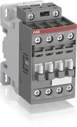
Ordering
1 piece
85364900
Popular Downloads
Dimensions
45 mm
77 mm
86 mm
0.31 kg
Technical
3
0
1
0
3P
IEC/EN 60947-1, IEC/EN 60947-4-1, UL 60335-2-40 LZGH2 A2L, UL 60947-4-1, CSA C22.2 No. 60335-2-40 LZGH2 A2L, CSA C22.2 No. 60947-4-1
Auxiliary Circuit 690 V
Main Circuit 690 V
Auxiliary Circuit 690 V
Main Circuit 690 V
Auxiliary Circuit 50 / 60 Hz
Control Circuit 50 / 60 Hz
Main Circuit 50 / 60 Hz
Auxiliary Circuit 50 / 60 Hz
Control Circuit 50 / 60 Hz
Main Circuit 50 / 60 Hz
acc. to IEC 60947-4-1, Open Contactors Θ = 40 °C 35 A
acc. to IEC 60947-5-1, Θ = 40 °C 16 A
acc. to IEC 60947-4-1, Open Contactors Θ = 40 °C 35 A
acc. to IEC 60947-5-1, Θ = 40 °C 16 A
(690 V) 40 °C 25 A
(690 V) 60 °C 25 A
(690 V) 70 °C 22 A
(690 V) 40 °C 25 A
(690 V) 60 °C 25 A
(690 V) 70 °C 22 A
(415 V) 60 °C 9 A
(440 V) 60 °C 9 A
(500 V) 60 °C 9.5 A
(690 V) 60 °C 7 A
(380 / 400 V) 60 °C 9 A
(220 / 230 / 240 V) 60 °C 9 A
(415 V) 60 °C 9 A
(440 V) 60 °C 9 A
(500 V) 60 °C 9.5 A
(690 V) 60 °C 7 A
(380 / 400 V) 60 °C 9 A
(220 / 230 / 240 V) 60 °C 9 A
(415 V) 60 °C 9 A
(440 V) 60 °C 9 A
(500 V) 60 °C 9.5 A
(690 V) 60 °C 7 A
(380 / 400 V) 60 °C 9 A
(220 / 230 / 240 V) 60 °C 9 A
(415 V) 60 °C 9 A
(440 V) 60 °C 9 A
(500 V) 60 °C 9.5 A
(690 V) 60 °C 7 A
(380 / 400 V) 60 °C 9 A
(220 / 230 / 240 V) 60 °C 9 A
(500 V) 2 A
(690 V) 2 A
(24 / 127 V) 6 A
(220 / 240 V) 4 A
(400 / 440 V) 3 A
(500 V) 2 A
(690 V) 2 A
(24 / 127 V) 6 A
(220 / 240 V) 4 A
(400 / 440 V) 3 A
(110 V) 1-Pole, 40 °C 10 A
(110 V) 1-Pole, 60 °C 10 A
(110 V) 1-Pole, 70 °C 10 A
(110 V) 2 Poles in Series, 40 °C 25 A
(110 V) 2 Poles in Series, 60 °C 25 A
(110 V) 2 Poles in Series, 70 °C 22 A
(110 V) 3 Poles in Series, 40 °C 25 A
(110 V) 3 Poles in Series, 60 °C 25 A
(110 V) 3 Poles in Series, 70 °C 22 A
(220 V) 2 Poles in Series, 40 °C 10 A
(220 V) 2 Poles in Series, 60 °C 10 A
(220 V) 2 Poles in Series, 70 °C 10 A
(220 V) 3 Poles in Series, 40 °C 25 A
(220 V) 3 Poles in Series, 60 °C 25 A
(220 V) 3 Poles in Series, 70 °C 22 A
(72 V) 1-Pole, 40 °C 25 A
(72 V) 1-Pole, 60 °C 25 A
(72 V) 1-Pole, 70 °C 22 A
(72 V) 2 Poles in Series, 40 °C 25 A
(72 V) 2 Poles in Series, 60 °C 25 A
(72 V) 2 Poles in Series, 70 °C 22 A
(72 V) 3 Poles in Series, 40 °C 25 A
(72 V) 3 Poles in Series, 60 °C 25 A
(72 V) 3 Poles in Series, 70 °C 22 A
(110 V) 1-Pole, 40 °C 10 A
(110 V) 1-Pole, 60 °C 10 A
(110 V) 1-Pole, 70 °C 10 A
(110 V) 2 Poles in Series, 40 °C 25 A
(110 V) 2 Poles in Series, 60 °C 25 A
(110 V) 2 Poles in Series, 70 °C 22 A
(110 V) 3 Poles in Series, 40 °C 25 A
(110 V) 3 Poles in Series, 60 °C 25 A
(110 V) 3 Poles in Series, 70 °C 22 A
(220 V) 2 Poles in Series, 40 °C 10 A
(110 V) 1-Pole, 40 °C 6 A
(110 V) 1-Pole, 60 °C 6 A
(110 V) 1-Pole, 70 °C 6 A
(110 V) 2 Poles in Series, 40 °C 25 A
(110 V) 2 Poles in Series, 60 °C 25 A
(110 V) 2 Poles in Series, 70 °C 22 A
(110 V) 3 Poles in Series, 40 °C 25 A
(110 V) 3 Poles in Series, 60 °C 25 A
(110 V) 3 Poles in Series, 70 °C 22 A
(220 V) 2 Poles in Series, 40 °C 6 A
(220 V) 2 Poles in Series, 60 °C 6 A
(220 V) 2 Poles in Series, 70 °C 6 A
(220 V) 3 Poles in Series, 40 °C 25 A
(220 V) 3 Poles in Series, 60 °C 25 A
(220 V) 3 Poles in Series, 70 °C 22 A
(72 V) 1-Pole, 40 °C 25 A
(72 V) 1-Pole, 60 °C 25 A
(72 V) 1-Pole, 70 °C 22 A
(72 V) 2 Poles in Series, 40 °C 25 A
(72 V) 2 Poles in Series, 60 °C 25 A
(72 V) 2 Poles in Series, 70 °C 22 A
(72 V) 3 Poles in Series, 40 °C 25 A
(72 V) 3 Poles in Series, 60 °C 25 A
(72 V) 3 Poles in Series, 70 °C 22 A
(110 V) 1-Pole, 40 °C 6 A
(110 V) 1-Pole, 60 °C 6 A
(110 V) 1-Pole, 70 °C 6 A
(110 V) 2 Poles in Series, 40 °C 25 A
(110 V) 2 Poles in Series, 60 °C 25 A
(110 V) 2 Poles in Series, 70 °C 22 A
(110 V) 3 Poles in Series, 40 °C 25 A
(110 V) 3 Poles in Series, 60 °C 25 A
(110 V) 3 Poles in Series, 70 °C 22 A
(220 V) 2 Poles in Series, 40 °C 6 A
(110 V) 1-Pole, 40 °C 4 A
(110 V) 1-Pole, 60 °C 4 A
(110 V) 1-Pole, 70 °C 4 A
(110 V) 2 Poles in Series, 40 °C 10 A
(110 V) 2 Poles in Series, 60 °C 10 A
(110 V) 2 Poles in Series, 70 °C 10 A
(110 V) 3 Poles in Series, 40 °C 25 A
(110 V) 3 Poles in Series, 60 °C 25 A
(110 V) 3 Poles in Series, 70 °C 22 A
(220 V) 2 Poles in Series, 40 °C 4 A
(220 V) 2 Poles in Series, 60 °C 4 A
(220 V) 2 Poles in Series, 70 °C 4 A
(220 V) 3 Poles in Series, 40 °C 9 A
(220 V) 3 Poles in Series, 60 °C 9 A
(220 V) 3 Poles in Series, 70 °C 9 A
(72 V) 1-Pole, 40 °C 9 A
(72 V) 1-Pole, 60 °C 9 A
(72 V) 1-Pole, 70 °C 9 A
(72 V) 2 Poles in Series, 40 °C 25 A
(72 V) 2 Poles in Series, 60 °C 25 A
(72 V) 2 Poles in Series, 70 °C 22 A
(72 V) 3 Poles in Series, 40 °C 25 A
(72 V) 3 Poles in Series, 60 °C 25 A
(72 V) 3 Poles in Series, 70 °C 22 A
(110 V) 1-Pole, 40 °C 4 A
(110 V) 1-Pole, 60 °C 4 A
(110 V) 1-Pole, 70 °C 4 A
(110 V) 2 Poles in Series, 40 °C 10 A
(110 V) 2 Poles in Series, 60 °C 10 A
(110 V) 2 Poles in Series, 70 °C 10 A
(110 V) 3 Poles in Series, 40 °C 25 A
(110 V) 3 Poles in Series, 60 °C 25 A
(110 V) 3 Poles in Series, 70 °C 22 A
(220 V) 2 Poles in Series, 40 °C 4 A
(24 V) 6 A / 144 W
(48 V) 2.8 A / 134 W
(72 V) 1 A / 72 W
(110 V) 0.55 A / 60 W
(125 V) 0.55 A / 69 W
(220 V) 0.27 A / 60 W
(250 V) 0.27 A / 68 W
(400 V) 0.15 A / 60 W
(500 V) 0.13 A / 65 W
(600 V) 0.1 A / 60 W
(24 V) 6 A / 144 W
(48 V) 2.8 A / 134 W
(72 V) 1 A / 72 W
(110 V) 0.55 A / 60 W
(125 V) 0.55 A / 69 W
(220 V) 0.27 A / 60 W
(250 V) 0.27 A / 68 W
(400 V) 0.15 A / 60 W
(500 V) 0.13 A / 65 W
(600 V) 0.1 A / 60 W
(400 V) 4 kW
(415 V) 4 kW
(440 V) 4 kW
(500 V) 5.5 kW
(690 V) 5.5 kW
(380 / 400 V) 4 kW
(220 / 230 / 240 V) 2.2 kW
(400 V) 4 kW
(415 V) 4 kW
(440 V) 4 kW
(500 V) 5.5 kW
(690 V) 5.5 kW
(380 / 400 V) 4 kW
(220 / 230 / 240 V) 2.2 kW
(415 V) 4 kW
(440 V) 4 kW
(500 V) 5.5 kW
(690 V) 5.5 kW
(380 / 400 V) 4 kW
(220 / 230 / 240 V) 2.2 kW
(415 V) 4 kW
(440 V) 4 kW
(500 V) 5.5 kW
(690 V) 5.5 kW
(380 / 400 V) 4 kW
(220 / 230 / 240 V) 2.2 kW
at 40 °C Ambient Temp, in Free Air, from a Cold State 10 s 150 A
at 40 °C Ambient Temp, in Free Air, from a Cold State 15 min 35 A
at 40 °C Ambient Temp, in Free Air, from a Cold State 1 min 60 A
at 40 °C Ambient Temp, in Free Air, from a Cold State 1 s 300 A
at 40 °C Ambient Temp, in Free Air, from a Cold State 30 s 80 A
for 0.1 s 140 A
for 1 s 100 A
at 40 °C Ambient Temp, in Free Air, from a Cold State 10 s 150 A
at 40 °C Ambient Temp, in Free Air, from a Cold State 15 min 35 A
at 40 °C Ambient Temp, in Free Air, from a Cold State 1 min 60 A
at 40 °C Ambient Temp, in Free Air, from a Cold State 1 s 300 A
at 40 °C Ambient Temp, in Free Air, from a Cold State 30 s 80 A
for 0.1 s 140 A
for 1 s 100 A
cos phi=0.45 (cos phi=0.35 for Ie > 100 A) at 440 V 250 A
cos phi=0.45 (cos phi=0.35 for Ie > 100 A) at 690 V 106 A
cos phi=0.45 (cos phi=0.35 for Ie > 100 A) at 440 V 250 A
cos phi=0.45 (cos phi=0.35 for Ie > 100 A) at 690 V 106 A
acc. to IEC 60947-4-1 690 V
acc. to IEC 60947-5-1 690 V
acc. to UL/CSA 600 V
acc. to IEC 60947-4-1 690 V
acc. to IEC 60947-5-1 690 V
acc. to UL/CSA 600 V
6 kV
(AC-1) 600 cycles per hour
(AC-15) 1200 cycles per hour
(AC-2 / AC-4) 300 cycles per hour
(AC-3) 1200 cycles per hour
(DC-13) 900 cycles per hour
(AC-1) 600 cycles per hour
(AC-15) 1200 cycles per hour
(AC-2 / AC-4) 300 cycles per hour
(AC-3) 1200 cycles per hour
(DC-13) 900 cycles per hour
3600 cycles per hour
50 Hz 24 ... 60 V
60 Hz 24 ... 60 V
DC Operation 20 ... 60 V
50 Hz 24 ... 60 V
60 Hz 24 ... 60 V
DC Operation 20 ... 60 V
at 6 A per Pole 0.1 W
at Rated Operating Conditions AC-1 per Pole 0.8 W
at Rated Operating Conditions AC-3 per Pole 0.1 W
at 6 A per Pole 0.1 W
at Rated Operating Conditions AC-1 per Pole 0.8 W
at Rated Operating Conditions AC-3 per Pole 0.1 W
Between Coil De-energization and NC Contact Closing 13 ... 98 ms
Between Coil De-energization and NO Contact Opening 11 ... 95 ms
Between Coil Energization and NC Contact Opening 38 ... 90 ms
Between Coil Energization and NO Contact Closing 40 ... 95 ms
Between Coil De-energization and NC Contact Closing 13 ... 98 ms
Between Coil De-energization and NO Contact Opening 11 ... 95 ms
Between Coil Energization and NC Contact Opening 38 ... 90 ms
Between Coil Energization and NO Contact Closing 40 ... 95 ms
TH35-15 (35 x 15 mm Mounting Rail) acc. to IEC 60715
TH35-7.5 (35 x 7.5 mm Mounting Rail) acc. to IEC 60715
TH35-15 (35 x 15 mm Mounting Rail) acc. to IEC 60715
TH35-7.5 (35 x 7.5 mm Mounting Rail) acc. to IEC 60715
2 x M4 Screws Placed Diagonally
Flexible with Ferrule 1/2x 0.75 ... 6 mm²
Flexible with Insulated Ferrule 1x 0.75 ... 4 mm²
Flexible with Insulated Ferrule 2x 0.75 ... 2.5 mm²
Rigid Solid 1/2x 1 ... 4 mm²
Rigid Stranded 1/2x 1 ... 6 mm²
Flexible with Ferrule 1/2x 0.75 ... 6 mm²
Flexible with Insulated Ferrule 1x 0.75 ... 4 mm²
Flexible with Insulated Ferrule 2x 0.75 ... 2.5 mm²
Rigid Solid 1/2x 1 ... 4 mm²
Rigid Stranded 1/2x 1 ... 6 mm²
Flexible with Ferrule 1/2x 0.75 ... 2.5 mm²
Flexible with Insulated Ferrule 2x 0.75 ... 1.5 mm²
Flexible with Insulated Ferrule 1x 0.75 ... 2.5 mm²
Rigid Solid 1/2x 1 ... 2.5 mm²
Rigid Stranded 1/2x 1 ... 2.5 mm²
Flexible with Ferrule 1/2x 0.75 ... 2.5 mm²
Flexible with Insulated Ferrule 2x 0.75 ... 1.5 mm²
Flexible with Insulated Ferrule 1x 0.75 ... 2.5 mm²
Rigid Solid 1/2x 1 ... 2.5 mm²
Rigid Stranded 1/2x 1 ... 2.5 mm²
Flexible with Ferrule 1/2x 0.75 ... 2.5 mm²
Flexible with Insulated Ferrule 1x 0.75 ... 2.5 mm²
Flexible with Insulated Ferrule 2x 0.75 ... 1.5 mm²
Rigid Solid 1/2x 1 ... 2.5 mm²
Rigid Stranded 1/2x 1 ... 2.5 mm²
Flexible with Ferrule 1/2x 0.75 ... 2.5 mm²
Flexible with Insulated Ferrule 1x 0.75 ... 2.5 mm²
Flexible with Insulated Ferrule 2x 0.75 ... 1.5 mm²
Rigid Solid 1/2x 1 ... 2.5 mm²
Rigid Stranded 1/2x 1 ... 2.5 mm²
Auxiliary Circuit 10 mm
Control Circuit 10 mm
Main Circuit 10 mm
Auxiliary Circuit 10 mm
Control Circuit 10 mm
Main Circuit 10 mm
acc. to IEC 60529, IEC 60947-1, EN 60529 Auxiliary Terminals IP20
acc. to IEC 60529, IEC 60947-1, EN 60529 Coil Terminals IP20
acc. to IEC 60529, IEC 60947-1, EN 60529 Main Terminals IP20
acc. to IEC 60529, IEC 60947-1, EN 60529 Auxiliary Terminals IP20
acc. to IEC 60529, IEC 60947-1, EN 60529 Coil Terminals IP20
acc. to IEC 60529, IEC 60947-1, EN 60529 Main Terminals IP20
Auxiliary Circuit 1.2 N·m
Control Circuit 1.2 N·m
Main Circuit 1.5 N·m
Auxiliary Circuit 1.2 N·m
Control Circuit 1.2 N·m
Main Circuit 1.5 N·m
Screw Terminals
Block Contactor
Technical UL/CSA
00
9 A
(115 V AC) Single Phase 1/3 Hp
(200 V AC) Three Phase 1-1/2 Hp
(230 V AC) Single Phase 1 Hp
(230 V AC) Three Phase 1-1/2 Hp
(460 V AC) Three Phase 2 Hp
(575 V AC) Three Phase 2 Hp
(115 V AC) Single Phase 1/3 Hp
(200 V AC) Three Phase 1-1/2 Hp
(230 V AC) Single Phase 1 Hp
(230 V AC) Three Phase 1-1/2 Hp
(460 V AC) Three Phase 2 Hp
(575 V AC) Three Phase 2 Hp
Main Circuit 600 V
(600 V AC) 25 A
(120 V AC) Single Phase 3/4 hp
(200 ... 208 V AC) Three Phase 2 hp
(220 ... 240 V AC) Three Phase 2 hp
(240 V AC) Single Phase 1-1/2 hp
(440 ... 480 V AC) Three Phase 5 hp
(550 ... 600 V AC) Three Phase 7-1/2 hp
(120 V AC) Single Phase 3/4 hp
(200 ... 208 V AC) Three Phase 2 hp
(220 ... 240 V AC) Three Phase 2 hp
(240 V AC) Single Phase 1-1/2 hp
(440 ... 480 V AC) Three Phase 5 hp
(550 ... 600 V AC) Three Phase 7-1/2 hp
Rigid Solid 1/2x 16-10 AWG
Rigid Stranded 1/2x 16-10 AWG
Rigid Solid 1/2x 16-10 AWG
Rigid Stranded 1/2x 16-10 AWG
Rigid Solid 1/2x 18-14 AWG
Rigid Stranded 1/2x 18-14 AWG
Rigid Solid 1/2x 18-14 AWG
Rigid Stranded 1/2x 18-14 AWG
Rigid Solid 1/2x 18-14 AWG
Rigid Stranded 1/2x 18-14 AWG
Rigid Solid 1/2x 18-14 AWG
Rigid Stranded 1/2x 18-14 AWG
Auxiliary Circuit 11 in·lb
Control Circuit 11 in·lb
Main Circuit 13 in·lb
Auxiliary Circuit 11 in·lb
Control Circuit 11 in·lb
Main Circuit 13 in·lb
(120 V AC) Single Phase 13.8 A
(200 ... 208 V AC) Three Phase 7.8 A
(220 ... 240 V AC) Three Phase 6.8 A
(240 V AC) Single Phase 10 A
(440 ... 480 V AC) Three Phase 7.6 A
(550 ... 600 V AC) Three Phase 9 A
(120 V AC) Single Phase 13.8 A
(200 ... 208 V AC) Three Phase 7.8 A
(220 ... 240 V AC) Three Phase 6.8 A
(240 V AC) Single Phase 10 A
(440 ... 480 V AC) Three Phase 7.6 A
(550 ... 600 V AC) Three Phase 9 A
Environmental
Close to Contactor Fitted with Thermal O/L Relay -25 ... 60 °C
Close to Contactor without Thermal O/L Relay -40 ... 70 °C
Close to Contactor for Storage -60 ... +80 °C
Close to Contactor Fitted with Thermal O/L Relay -25 ... 60 °C
Close to Contactor without Thermal O/L Relay -40 ... 70 °C
Close to Contactor for Storage -60 ... +80 °C
Category B according to IEC 60947-1 Annex Q
Without Derating 3000 m
Closed, Shock Direction: B1 25 g
Open, Shock Direction: B1 5 g
Shock Direction: A 30 g
Shock Direction: B2 15 g
Shock Direction: C1 25 g
Shock Direction: C2 25 g
Closed, Shock Direction: B1 25 g
Open, Shock Direction: B1 5 g
Shock Direction: A 30 g
Shock Direction: B2 15 g
Shock Direction: C1 25 g
Shock Direction: C2 25 g
4g Closed Position & 2g Open position 5 ... 300 Hz
3
Material Compliance
Following EU Directive 2011/65/EU and Amendment 2015/863 July 22, 2019
6f58c756-afeb-453f-a363-0ee8b476dfbb France
3deb17f8-9c06-4eb7-899b-a1c153ca99d5 Sweden
0f0bf2aa-d6d9-4eee-913c-afad142f1786 Poland
2fe90688-ac10-4a3e-9e34-9df1246337a8 France
6add860b-bcda-4fa1-a192-e65220454cb6 Germany
132698d2-18ef-4b27-933d-ac6b48788aef Sweden
3d2ffd99-f19e-4059-868e-7317979818fa Finland
6e95ad43-1bde-4887-8bfd-1ab0abc6d58c Italy
6d6b0b90-5387-435d-9e4a-b07c3d29effb Netherlands
86a0b16d-eacd-4670-a411-941e42e9b83e Greece
b9defdc9-9715-4311-bbf4-033c39b27e10 Portugal
eb94c07f-225d-4b89-a596-0812813e017b Germany
fbfa9e77-1a34-4102-8448-9525fe8f6cce Germany
1e49ea39-e5ab-4593-8e49-472da9b4fdb8 Denmark
eae0abce-df0b-49dd-a056-84fa83edc5d3 Germany
a93e32b5-186d-4858-9be8-d93c4940de67 Czech Republic
c13c4ab7-c4cb-4d7d-91be-fab3c4c7b416 Poland
7be29633-a94c-46f3-b246-0ca792615ffe Germany
4c5fee66-9428-4135-a8ca-8d6de49c5410 Poland
bbc35c5d-a088-4347-b745-bc6ea5a49dc3 Norway
f67726bb-0e6b-489a-8869-1fe8a5315b95 Spain
f88fa7e5-0286-4ed6-a1be-c127d9f791a4 Hungary
9c0714c2-a501-442d-908b-6faab74e2066 Belgium
ab9cbd72-01d1-421e-b9c9-5509fcd097f6 Bulgaria
3deb17f8-9c06-4eb7-899b-a1c153ca99d5 Sweden
0f0bf2aa-d6d9-4eee-913c-afad142f1786 Poland
2fe90688-ac10-4a3e-9e34-9df1246337a8 France
6add860b-bcda-4fa1-a192-e65220454cb6 Germany
132698d2-18ef-4b27-933d-ac6b48788aef Sweden
3d2ffd99-f19e-4059-868e-7317979818fa Finland
6e95ad43-1bde-4887-8bfd-1ab0abc6d58c Italy
6d6b0b90-5387-435d-9e4a-b07c3d29effb Netherlands
86a0b16d-eacd-4670-a411-941e42e9b83e Greece
b9defdc9-9715-4311-bbf4-033c39b27e10 Portugal
Business To Business
5. Small Equipment (No External Dimension More Than 50 cm)
ABB EcoSolutions
Recycled Cardboard - 86 %
Recycled Metal - 28 %
Certificates and Declarations
Container Information
box 1 piece
87 mm
79 mm
47 mm
0.31 kg
3471523113213
box 27 piece
250 mm
300 mm
315 mm
8.37 kg
External Classifications and Standards
Q
EC000066 - Power contactor, AC switching
EC000066 - Power contactor, AC switching
EC000066 - Power contactor, AC switching
V11.0 : 27371003
39121529
4758 >> Iec Contactors
3706210
3210005

Ordering
1 piece
85364900
Popular Downloads
Dimensions
45 mm
110.5 mm
86 mm
0.36 kg
Technical
3
0
2
2
3P
IEC/EN 60947-1, IEC/EN 60947-4-1, UL 60335-2-40 LZGH2 A2L, UL 60947-4-1, CSA C22.2 No. 60335-2-40 LZGH2 A2L, CSA C22.2 No. 60947-4-1
Auxiliary Circuit 690 V
Main Circuit 690 V
Auxiliary Circuit 690 V
Main Circuit 690 V
Auxiliary Circuit 50 / 60 Hz
Control Circuit 50 / 60 Hz
Main Circuit 50 / 60 Hz
Auxiliary Circuit 50 / 60 Hz
Control Circuit 50 / 60 Hz
Main Circuit 50 / 60 Hz
acc. to IEC 60947-4-1, Open Contactors Θ = 40 °C 35 A
acc. to IEC 60947-5-1, Θ = 40 °C 16 A
acc. to IEC 60947-4-1, Open Contactors Θ = 40 °C 35 A
acc. to IEC 60947-5-1, Θ = 40 °C 16 A
(690 V) 40 °C 25 A
(690 V) 60 °C 25 A
(690 V) 70 °C 22 A
(690 V) 40 °C 25 A
(690 V) 60 °C 25 A
(690 V) 70 °C 22 A
(415 V) 60 °C 9 A
(440 V) 60 °C 9 A
(500 V) 60 °C 9.5 A
(690 V) 60 °C 7 A
(380 / 400 V) 60 °C 9 A
(220 / 230 / 240 V) 60 °C 9 A
(415 V) 60 °C 9 A
(440 V) 60 °C 9 A
(500 V) 60 °C 9.5 A
(690 V) 60 °C 7 A
(380 / 400 V) 60 °C 9 A
(220 / 230 / 240 V) 60 °C 9 A
(415 V) 60 °C 9 A
(440 V) 60 °C 9 A
(500 V) 60 °C 9.5 A
(690 V) 60 °C 7 A
(380 / 400 V) 60 °C 9 A
(220 / 230 / 240 V) 60 °C 9 A
(415 V) 60 °C 9 A
(440 V) 60 °C 9 A
(500 V) 60 °C 9.5 A
(690 V) 60 °C 7 A
(380 / 400 V) 60 °C 9 A
(220 / 230 / 240 V) 60 °C 9 A
(500 V) 2 A
(690 V) 2 A
(24 / 127 V) 6 A
(220 / 240 V) 4 A
(400 / 440 V) 3 A
(500 V) 2 A
(690 V) 2 A
(24 / 127 V) 6 A
(220 / 240 V) 4 A
(400 / 440 V) 3 A
(110 V) 1-Pole, 40 °C 10 A
(110 V) 1-Pole, 60 °C 10 A
(110 V) 1-Pole, 70 °C 10 A
(110 V) 2 Poles in Series, 40 °C 25 A
(110 V) 2 Poles in Series, 60 °C 25 A
(110 V) 2 Poles in Series, 70 °C 22 A
(110 V) 3 Poles in Series, 40 °C 25 A
(110 V) 3 Poles in Series, 60 °C 25 A
(110 V) 3 Poles in Series, 70 °C 22 A
(220 V) 2 Poles in Series, 40 °C 10 A
(220 V) 2 Poles in Series, 60 °C 10 A
(220 V) 2 Poles in Series, 70 °C 10 A
(220 V) 3 Poles in Series, 40 °C 25 A
(220 V) 3 Poles in Series, 60 °C 25 A
(220 V) 3 Poles in Series, 70 °C 22 A
(72 V) 1-Pole, 40 °C 25 A
(72 V) 1-Pole, 60 °C 25 A
(72 V) 1-Pole, 70 °C 22 A
(72 V) 2 Poles in Series, 40 °C 25 A
(72 V) 2 Poles in Series, 60 °C 25 A
(72 V) 2 Poles in Series, 70 °C 22 A
(72 V) 3 Poles in Series, 40 °C 25 A
(72 V) 3 Poles in Series, 60 °C 25 A
(72 V) 3 Poles in Series, 70 °C 22 A
(110 V) 1-Pole, 40 °C 10 A
(110 V) 1-Pole, 60 °C 10 A
(110 V) 1-Pole, 70 °C 10 A
(110 V) 2 Poles in Series, 40 °C 25 A
(110 V) 2 Poles in Series, 60 °C 25 A
(110 V) 2 Poles in Series, 70 °C 22 A
(110 V) 3 Poles in Series, 40 °C 25 A
(110 V) 3 Poles in Series, 60 °C 25 A
(110 V) 3 Poles in Series, 70 °C 22 A
(220 V) 2 Poles in Series, 40 °C 10 A
(110 V) 1-Pole, 40 °C 6 A
(110 V) 1-Pole, 60 °C 6 A
(110 V) 1-Pole, 70 °C 6 A
(110 V) 2 Poles in Series, 40 °C 25 A
(110 V) 2 Poles in Series, 60 °C 25 A
(110 V) 2 Poles in Series, 70 °C 22 A
(110 V) 3 Poles in Series, 40 °C 25 A
(110 V) 3 Poles in Series, 60 °C 25 A
(110 V) 3 Poles in Series, 70 °C 22 A
(220 V) 2 Poles in Series, 40 °C 6 A
(220 V) 2 Poles in Series, 60 °C 6 A
(220 V) 2 Poles in Series, 70 °C 6 A
(220 V) 3 Poles in Series, 40 °C 25 A
(220 V) 3 Poles in Series, 60 °C 25 A
(220 V) 3 Poles in Series, 70 °C 22 A
(72 V) 1-Pole, 40 °C 25 A
(72 V) 1-Pole, 60 °C 25 A
(72 V) 1-Pole, 70 °C 22 A
(72 V) 2 Poles in Series, 40 °C 25 A
(72 V) 2 Poles in Series, 60 °C 25 A
(72 V) 2 Poles in Series, 70 °C 22 A
(72 V) 3 Poles in Series, 40 °C 25 A
(72 V) 3 Poles in Series, 60 °C 25 A
(72 V) 3 Poles in Series, 70 °C 22 A
(110 V) 1-Pole, 40 °C 6 A
(110 V) 1-Pole, 60 °C 6 A
(110 V) 1-Pole, 70 °C 6 A
(110 V) 2 Poles in Series, 40 °C 25 A
(110 V) 2 Poles in Series, 60 °C 25 A
(110 V) 2 Poles in Series, 70 °C 22 A
(110 V) 3 Poles in Series, 40 °C 25 A
(110 V) 3 Poles in Series, 60 °C 25 A
(110 V) 3 Poles in Series, 70 °C 22 A
(220 V) 2 Poles in Series, 40 °C 6 A
(110 V) 1-Pole, 40 °C 4 A
(110 V) 1-Pole, 60 °C 4 A
(110 V) 1-Pole, 70 °C 4 A
(110 V) 2 Poles in Series, 40 °C 10 A
(110 V) 2 Poles in Series, 60 °C 10 A
(110 V) 2 Poles in Series, 70 °C 10 A
(110 V) 3 Poles in Series, 40 °C 25 A
(110 V) 3 Poles in Series, 60 °C 25 A
(110 V) 3 Poles in Series, 70 °C 22 A
(220 V) 2 Poles in Series, 40 °C 4 A
(220 V) 2 Poles in Series, 60 °C 4 A
(220 V) 2 Poles in Series, 70 °C 4 A
(220 V) 3 Poles in Series, 40 °C 9 A
(220 V) 3 Poles in Series, 60 °C 9 A
(220 V) 3 Poles in Series, 70 °C 9 A
(72 V) 1-Pole, 40 °C 9 A
(72 V) 1-Pole, 60 °C 9 A
(72 V) 1-Pole, 70 °C 9 A
(72 V) 2 Poles in Series, 40 °C 25 A
(72 V) 2 Poles in Series, 60 °C 25 A
(72 V) 2 Poles in Series, 70 °C 22 A
(72 V) 3 Poles in Series, 40 °C 25 A
(72 V) 3 Poles in Series, 60 °C 25 A
(72 V) 3 Poles in Series, 70 °C 22 A
(110 V) 1-Pole, 40 °C 4 A
(110 V) 1-Pole, 60 °C 4 A
(110 V) 1-Pole, 70 °C 4 A
(110 V) 2 Poles in Series, 40 °C 10 A
(110 V) 2 Poles in Series, 60 °C 10 A
(110 V) 2 Poles in Series, 70 °C 10 A
(110 V) 3 Poles in Series, 40 °C 25 A
(110 V) 3 Poles in Series, 60 °C 25 A
(110 V) 3 Poles in Series, 70 °C 22 A
(220 V) 2 Poles in Series, 40 °C 4 A
(24 V) 6 A / 144 W
(48 V) 2.8 A / 134 W
(72 V) 1 A / 72 W
(110 V) 0.55 A / 60 W
(125 V) 0.55 A / 69 W
(220 V) 0.27 A / 60 W
(250 V) 0.27 A / 68 W
(400 V) 0.15 A / 60 W
(500 V) 0.13 A / 65 W
(600 V) 0.1 A / 60 W
(24 V) 6 A / 144 W
(48 V) 2.8 A / 134 W
(72 V) 1 A / 72 W
(110 V) 0.55 A / 60 W
(125 V) 0.55 A / 69 W
(220 V) 0.27 A / 60 W
(250 V) 0.27 A / 68 W
(400 V) 0.15 A / 60 W
(500 V) 0.13 A / 65 W
(600 V) 0.1 A / 60 W
(400 V) 4 kW
(415 V) 4 kW
(440 V) 4 kW
(500 V) 5.5 kW
(690 V) 5.5 kW
(380 / 400 V) 4 kW
(220 / 230 / 240 V) 2.2 kW
(400 V) 4 kW
(415 V) 4 kW
(440 V) 4 kW
(500 V) 5.5 kW
(690 V) 5.5 kW
(380 / 400 V) 4 kW
(220 / 230 / 240 V) 2.2 kW
(415 V) 4 kW
(440 V) 4 kW
(500 V) 5.5 kW
(690 V) 5.5 kW
(380 / 400 V) 4 kW
(220 / 230 / 240 V) 2.2 kW
(415 V) 4 kW
(440 V) 4 kW
(500 V) 5.5 kW
(690 V) 5.5 kW
(380 / 400 V) 4 kW
(220 / 230 / 240 V) 2.2 kW
at 40 °C Ambient Temp, in Free Air, from a Cold State 10 s 150 A
at 40 °C Ambient Temp, in Free Air, from a Cold State 15 min 35 A
at 40 °C Ambient Temp, in Free Air, from a Cold State 1 min 60 A
at 40 °C Ambient Temp, in Free Air, from a Cold State 1 s 300 A
at 40 °C Ambient Temp, in Free Air, from a Cold State 30 s 80 A
for 0.1 s 140 A
for 1 s 100 A
at 40 °C Ambient Temp, in Free Air, from a Cold State 10 s 150 A
at 40 °C Ambient Temp, in Free Air, from a Cold State 15 min 35 A
at 40 °C Ambient Temp, in Free Air, from a Cold State 1 min 60 A
at 40 °C Ambient Temp, in Free Air, from a Cold State 1 s 300 A
at 40 °C Ambient Temp, in Free Air, from a Cold State 30 s 80 A
for 0.1 s 140 A
for 1 s 100 A
cos phi=0.45 (cos phi=0.35 for Ie > 100 A) at 440 V 250 A
cos phi=0.45 (cos phi=0.35 for Ie > 100 A) at 690 V 106 A
cos phi=0.45 (cos phi=0.35 for Ie > 100 A) at 440 V 250 A
cos phi=0.45 (cos phi=0.35 for Ie > 100 A) at 690 V 106 A
acc. to IEC 60947-4-1 690 V
acc. to IEC 60947-5-1 690 V
acc. to UL/CSA 600 V
acc. to IEC 60947-4-1 690 V
acc. to IEC 60947-5-1 690 V
acc. to UL/CSA 600 V
6 kV
(AC-1) 600 cycles per hour
(AC-15) 1200 cycles per hour
(AC-2 / AC-4) 300 cycles per hour
(AC-3) 1200 cycles per hour
(DC-13) 900 cycles per hour
(AC-1) 600 cycles per hour
(AC-15) 1200 cycles per hour
(AC-2 / AC-4) 300 cycles per hour
(AC-3) 1200 cycles per hour
(DC-13) 900 cycles per hour
3600 cycles per hour
50 Hz 24 ... 60 V
60 Hz 24 ... 60 V
DC Operation 20 ... 60 V
50 Hz 24 ... 60 V
60 Hz 24 ... 60 V
DC Operation 20 ... 60 V
at 6 A per Pole 0.1 W
at Rated Operating Conditions AC-1 per Pole 0.8 W
at Rated Operating Conditions AC-3 per Pole 0.1 W
at 6 A per Pole 0.1 W
at Rated Operating Conditions AC-1 per Pole 0.8 W
at Rated Operating Conditions AC-3 per Pole 0.1 W
Between Coil De-energization and NC Contact Closing 13 ... 98 ms
Between Coil De-energization and NO Contact Opening 11 ... 95 ms
Between Coil Energization and NC Contact Opening 38 ... 90 ms
Between Coil Energization and NO Contact Closing 40 ... 95 ms
Between Coil De-energization and NC Contact Closing 13 ... 98 ms
Between Coil De-energization and NO Contact Opening 11 ... 95 ms
Between Coil Energization and NC Contact Opening 38 ... 90 ms
Between Coil Energization and NO Contact Closing 40 ... 95 ms
TH35-15 (35 x 15 mm Mounting Rail) acc. to IEC 60715
TH35-7.5 (35 x 7.5 mm Mounting Rail) acc. to IEC 60715
TH35-15 (35 x 15 mm Mounting Rail) acc. to IEC 60715
TH35-7.5 (35 x 7.5 mm Mounting Rail) acc. to IEC 60715
2 x M4 Screws Placed Diagonally
Flexible with Ferrule 1/2x 0.75 ... 6 mm²
Flexible with Insulated Ferrule 1x 0.75 ... 4 mm²
Flexible with Insulated Ferrule 2x 0.75 ... 2.5 mm²
Rigid Solid 1/2x 1 ... 4 mm²
Rigid Stranded 1/2x 1 ... 6 mm²
Flexible with Ferrule 1/2x 0.75 ... 6 mm²
Flexible with Insulated Ferrule 1x 0.75 ... 4 mm²
Flexible with Insulated Ferrule 2x 0.75 ... 2.5 mm²
Rigid Solid 1/2x 1 ... 4 mm²
Rigid Stranded 1/2x 1 ... 6 mm²
Flexible with Ferrule 1/2x 0.75 ... 2.5 mm²
Flexible with Insulated Ferrule 2x 0.75 ... 1.5 mm²
Flexible with Insulated Ferrule 1x 0.75 ... 2.5 mm²
Rigid Solid 1/2x 1 ... 2.5 mm²
Rigid Stranded 1/2x 1 ... 2.5 mm²
Flexible with Ferrule 1/2x 0.75 ... 2.5 mm²
Flexible with Insulated Ferrule 2x 0.75 ... 1.5 mm²
Flexible with Insulated Ferrule 1x 0.75 ... 2.5 mm²
Rigid Solid 1/2x 1 ... 2.5 mm²
Rigid Stranded 1/2x 1 ... 2.5 mm²
Flexible with Ferrule 1/2x 0.75 ... 2.5 mm²
Flexible with Insulated Ferrule 1x 0.75 ... 2.5 mm²
Flexible with Insulated Ferrule 2x 0.75 ... 1.5 mm²
Rigid Solid 1/2x 1 ... 2.5 mm²
Rigid Stranded 1/2x 1 ... 2.5 mm²
Flexible with Ferrule 1/2x 0.75 ... 2.5 mm²
Flexible with Insulated Ferrule 1x 0.75 ... 2.5 mm²
Flexible with Insulated Ferrule 2x 0.75 ... 1.5 mm²
Rigid Solid 1/2x 1 ... 2.5 mm²
Rigid Stranded 1/2x 1 ... 2.5 mm²
Auxiliary Circuit 10 mm
Control Circuit 10 mm
Main Circuit 10 mm
Auxiliary Circuit 10 mm
Control Circuit 10 mm
Main Circuit 10 mm
acc. to IEC 60529, IEC 60947-1, EN 60529 Auxiliary Terminals IP20
acc. to IEC 60529, IEC 60947-1, EN 60529 Coil Terminals IP20
acc. to IEC 60529, IEC 60947-1, EN 60529 Main Terminals IP20
acc. to IEC 60529, IEC 60947-1, EN 60529 Auxiliary Terminals IP20
acc. to IEC 60529, IEC 60947-1, EN 60529 Coil Terminals IP20
acc. to IEC 60529, IEC 60947-1, EN 60529 Main Terminals IP20
Auxiliary Circuit 1.2 N·m
Control Circuit 1.2 N·m
Main Circuit 1.5 N·m
Auxiliary Circuit 1.2 N·m
Control Circuit 1.2 N·m
Main Circuit 1.5 N·m
Screw Terminals
Block Contactor
Technical UL/CSA
00
9 A
(115 V AC) Single Phase 1/3 Hp
(200 V AC) Three Phase 1-1/2 Hp
(230 V AC) Single Phase 1 Hp
(230 V AC) Three Phase 1-1/2 Hp
(460 V AC) Three Phase 2 Hp
(575 V AC) Three Phase 2 Hp
(115 V AC) Single Phase 1/3 Hp
(200 V AC) Three Phase 1-1/2 Hp
(230 V AC) Single Phase 1 Hp
(230 V AC) Three Phase 1-1/2 Hp
(460 V AC) Three Phase 2 Hp
(575 V AC) Three Phase 2 Hp
Main Circuit 600 V
(600 V AC) 25 A
(120 V AC) Single Phase 3/4 hp
(200 ... 208 V AC) Three Phase 2 hp
(220 ... 240 V AC) Three Phase 2 hp
(240 V AC) Single Phase 1-1/2 hp
(440 ... 480 V AC) Three Phase 5 hp
(550 ... 600 V AC) Three Phase 7-1/2 hp
(120 V AC) Single Phase 3/4 hp
(200 ... 208 V AC) Three Phase 2 hp
(220 ... 240 V AC) Three Phase 2 hp
(240 V AC) Single Phase 1-1/2 hp
(440 ... 480 V AC) Three Phase 5 hp
(550 ... 600 V AC) Three Phase 7-1/2 hp
Rigid Solid 1/2x 16-10 AWG
Rigid Stranded 1/2x 16-10 AWG
Rigid Solid 1/2x 16-10 AWG
Rigid Stranded 1/2x 16-10 AWG
Rigid Solid 1/2x 18-14 AWG
Rigid Stranded 1/2x 18-14 AWG
Rigid Solid 1/2x 18-14 AWG
Rigid Stranded 1/2x 18-14 AWG
Rigid Solid 1/2x 18-14 AWG
Rigid Stranded 1/2x 18-14 AWG
Rigid Solid 1/2x 18-14 AWG
Rigid Stranded 1/2x 18-14 AWG
Auxiliary Circuit 11 in·lb
Control Circuit 11 in·lb
Main Circuit 13 in·lb
Auxiliary Circuit 11 in·lb
Control Circuit 11 in·lb
Main Circuit 13 in·lb
(120 V AC) Single Phase 13.8 A
(200 ... 208 V AC) Three Phase 7.8 A
(220 ... 240 V AC) Three Phase 6.8 A
(240 V AC) Single Phase 10 A
(440 ... 480 V AC) Three Phase 7.6 A
(550 ... 600 V AC) Three Phase 9 A
(120 V AC) Single Phase 13.8 A
(200 ... 208 V AC) Three Phase 7.8 A
(220 ... 240 V AC) Three Phase 6.8 A
(240 V AC) Single Phase 10 A
(440 ... 480 V AC) Three Phase 7.6 A
(550 ... 600 V AC) Three Phase 9 A
Environmental
Close to Contactor Fitted with Thermal O/L Relay -25 ... 60 °C
Close to Contactor without Thermal O/L Relay -40 ... 70 °C
Close to Contactor for Storage -60 ... +80 °C
Close to Contactor Fitted with Thermal O/L Relay -25 ... 60 °C
Close to Contactor without Thermal O/L Relay -40 ... 70 °C
Close to Contactor for Storage -60 ... +80 °C
Category B according to IEC 60947-1 Annex Q
Without Derating 3000 m
Closed, Shock Direction: B1 25 g
Open, Shock Direction: B1 5 g
Shock Direction: A 30 g
Shock Direction: B2 15 g
Shock Direction: C1 25 g
Shock Direction: C2 25 g
Closed, Shock Direction: B1 25 g
Open, Shock Direction: B1 5 g
Shock Direction: A 30 g
Shock Direction: B2 15 g
Shock Direction: C1 25 g
Shock Direction: C2 25 g
4g Closed Position & 2g Open position 5 ... 300 Hz
3
Material Compliance
Following EU Directive 2011/65/EU and Amendment 2015/863 July 22, 2019
Business To Business
5. Small Equipment (No External Dimension More Than 50 cm)
ABB EcoSolutions
Recycled Cardboard - 86 %
Recycled Metal - 28 %
Certificates and Declarations
Container Information
box 1 piece
87 mm
113 mm
47 mm
0.36 kg
3471523113411
box 18 piece
250 mm
300 mm
315 mm
6.48 kg
External Classifications and Standards
Q
EC000066 - Power contactor, AC switching
EC000066 - Power contactor, AC switching
EC000066 - Power contactor, AC switching
V11.0 : 27371003
39121529
4758 >> Iec Contactors

Ordering
1 piece
85364900
Popular Downloads
Dimensions
45 mm
77 mm
86 mm
0.31 kg
Technical
3
0
1
0
3P
IEC/EN 60947-1, IEC/EN 60947-4-1, UL 60335-2-40 LZGH2 A2L, UL 60947-4-1, CSA C22.2 No. 60335-2-40 LZGH2 A2L, CSA C22.2 No. 60947-4-1
Auxiliary Circuit 690 V
Main Circuit 690 V
Auxiliary Circuit 690 V
Main Circuit 690 V
Auxiliary Circuit 50 / 60 Hz
Control Circuit 50 / 60 Hz
Main Circuit 50 / 60 Hz
Auxiliary Circuit 50 / 60 Hz
Control Circuit 50 / 60 Hz
Main Circuit 50 / 60 Hz
acc. to IEC 60947-4-1, Open Contactors Θ = 40 °C 35 A
acc. to IEC 60947-5-1, Θ = 40 °C 16 A
acc. to IEC 60947-4-1, Open Contactors Θ = 40 °C 35 A
acc. to IEC 60947-5-1, Θ = 40 °C 16 A
(690 V) 40 °C 25 A
(690 V) 60 °C 25 A
(690 V) 70 °C 22 A
(690 V) 40 °C 25 A
(690 V) 60 °C 25 A
(690 V) 70 °C 22 A
(415 V) 60 °C 9 A
(440 V) 60 °C 9 A
(500 V) 60 °C 9.5 A
(690 V) 60 °C 7 A
(380 / 400 V) 60 °C 9 A
(220 / 230 / 240 V) 60 °C 9 A
(415 V) 60 °C 9 A
(440 V) 60 °C 9 A
(500 V) 60 °C 9.5 A
(690 V) 60 °C 7 A
(380 / 400 V) 60 °C 9 A
(220 / 230 / 240 V) 60 °C 9 A
(415 V) 60 °C 9 A
(440 V) 60 °C 9 A
(500 V) 60 °C 9.5 A
(690 V) 60 °C 7 A
(380 / 400 V) 60 °C 9 A
(220 / 230 / 240 V) 60 °C 9 A
(415 V) 60 °C 9 A
(440 V) 60 °C 9 A
(500 V) 60 °C 9.5 A
(690 V) 60 °C 7 A
(380 / 400 V) 60 °C 9 A
(220 / 230 / 240 V) 60 °C 9 A
(500 V) 2 A
(690 V) 2 A
(24 / 127 V) 6 A
(220 / 240 V) 4 A
(400 / 440 V) 3 A
(500 V) 2 A
(690 V) 2 A
(24 / 127 V) 6 A
(220 / 240 V) 4 A
(400 / 440 V) 3 A
(110 V) 1-Pole, 40 °C 10 A
(110 V) 1-Pole, 60 °C 10 A
(110 V) 1-Pole, 70 °C 10 A
(110 V) 2 Poles in Series, 40 °C 25 A
(110 V) 2 Poles in Series, 60 °C 25 A
(110 V) 2 Poles in Series, 70 °C 22 A
(110 V) 3 Poles in Series, 40 °C 25 A
(110 V) 3 Poles in Series, 60 °C 25 A
(110 V) 3 Poles in Series, 70 °C 22 A
(220 V) 2 Poles in Series, 40 °C 10 A
(220 V) 2 Poles in Series, 60 °C 10 A
(220 V) 2 Poles in Series, 70 °C 10 A
(220 V) 3 Poles in Series, 40 °C 25 A
(220 V) 3 Poles in Series, 60 °C 25 A
(220 V) 3 Poles in Series, 70 °C 22 A
(72 V) 1-Pole, 40 °C 25 A
(72 V) 1-Pole, 60 °C 25 A
(72 V) 1-Pole, 70 °C 22 A
(72 V) 2 Poles in Series, 40 °C 25 A
(72 V) 2 Poles in Series, 60 °C 25 A
(72 V) 2 Poles in Series, 70 °C 22 A
(72 V) 3 Poles in Series, 40 °C 25 A
(72 V) 3 Poles in Series, 60 °C 25 A
(72 V) 3 Poles in Series, 70 °C 22 A
(110 V) 1-Pole, 40 °C 10 A
(110 V) 1-Pole, 60 °C 10 A
(110 V) 1-Pole, 70 °C 10 A
(110 V) 2 Poles in Series, 40 °C 25 A
(110 V) 2 Poles in Series, 60 °C 25 A
(110 V) 2 Poles in Series, 70 °C 22 A
(110 V) 3 Poles in Series, 40 °C 25 A
(110 V) 3 Poles in Series, 60 °C 25 A
(110 V) 3 Poles in Series, 70 °C 22 A
(220 V) 2 Poles in Series, 40 °C 10 A
(110 V) 1-Pole, 40 °C 6 A
(110 V) 1-Pole, 60 °C 6 A
(110 V) 1-Pole, 70 °C 6 A
(110 V) 2 Poles in Series, 40 °C 25 A
(110 V) 2 Poles in Series, 60 °C 25 A
(110 V) 2 Poles in Series, 70 °C 22 A
(110 V) 3 Poles in Series, 40 °C 25 A
(110 V) 3 Poles in Series, 60 °C 25 A
(110 V) 3 Poles in Series, 70 °C 22 A
(220 V) 2 Poles in Series, 40 °C 6 A
(220 V) 2 Poles in Series, 60 °C 6 A
(220 V) 2 Poles in Series, 70 °C 6 A
(220 V) 3 Poles in Series, 40 °C 25 A
(220 V) 3 Poles in Series, 60 °C 25 A
(220 V) 3 Poles in Series, 70 °C 22 A
(72 V) 1-Pole, 40 °C 25 A
(72 V) 1-Pole, 60 °C 25 A
(72 V) 1-Pole, 70 °C 22 A
(72 V) 2 Poles in Series, 40 °C 25 A
(72 V) 2 Poles in Series, 60 °C 25 A
(72 V) 2 Poles in Series, 70 °C 22 A
(72 V) 3 Poles in Series, 40 °C 25 A
(72 V) 3 Poles in Series, 60 °C 25 A
(72 V) 3 Poles in Series, 70 °C 22 A
(110 V) 1-Pole, 40 °C 6 A
(110 V) 1-Pole, 60 °C 6 A
(110 V) 1-Pole, 70 °C 6 A
(110 V) 2 Poles in Series, 40 °C 25 A
(110 V) 2 Poles in Series, 60 °C 25 A
(110 V) 2 Poles in Series, 70 °C 22 A
(110 V) 3 Poles in Series, 40 °C 25 A
(110 V) 3 Poles in Series, 60 °C 25 A
(110 V) 3 Poles in Series, 70 °C 22 A
(220 V) 2 Poles in Series, 40 °C 6 A
(110 V) 1-Pole, 40 °C 4 A
(110 V) 1-Pole, 60 °C 4 A
(110 V) 1-Pole, 70 °C 4 A
(110 V) 2 Poles in Series, 40 °C 10 A
(110 V) 2 Poles in Series, 60 °C 10 A
(110 V) 2 Poles in Series, 70 °C 10 A
(110 V) 3 Poles in Series, 40 °C 25 A
(110 V) 3 Poles in Series, 60 °C 25 A
(110 V) 3 Poles in Series, 70 °C 22 A
(220 V) 2 Poles in Series, 40 °C 4 A
(220 V) 2 Poles in Series, 60 °C 4 A
(220 V) 2 Poles in Series, 70 °C 4 A
(220 V) 3 Poles in Series, 40 °C 9 A
(220 V) 3 Poles in Series, 60 °C 9 A
(220 V) 3 Poles in Series, 70 °C 9 A
(72 V) 1-Pole, 40 °C 9 A
(72 V) 1-Pole, 60 °C 9 A
(72 V) 1-Pole, 70 °C 9 A
(72 V) 2 Poles in Series, 40 °C 25 A
(72 V) 2 Poles in Series, 60 °C 25 A
(72 V) 2 Poles in Series, 70 °C 22 A
(72 V) 3 Poles in Series, 40 °C 25 A
(72 V) 3 Poles in Series, 60 °C 25 A
(72 V) 3 Poles in Series, 70 °C 22 A
(110 V) 1-Pole, 40 °C 4 A
(110 V) 1-Pole, 60 °C 4 A
(110 V) 1-Pole, 70 °C 4 A
(110 V) 2 Poles in Series, 40 °C 10 A
(110 V) 2 Poles in Series, 60 °C 10 A
(110 V) 2 Poles in Series, 70 °C 10 A
(110 V) 3 Poles in Series, 40 °C 25 A
(110 V) 3 Poles in Series, 60 °C 25 A
(110 V) 3 Poles in Series, 70 °C 22 A
(220 V) 2 Poles in Series, 40 °C 4 A
(24 V) 6 A / 144 W
(48 V) 2.8 A / 134 W
(72 V) 1 A / 72 W
(110 V) 0.55 A / 60 W
(125 V) 0.55 A / 69 W
(220 V) 0.27 A / 60 W
(250 V) 0.27 A / 68 W
(400 V) 0.15 A / 60 W
(500 V) 0.13 A / 65 W
(600 V) 0.1 A / 60 W
(24 V) 6 A / 144 W
(48 V) 2.8 A / 134 W
(72 V) 1 A / 72 W
(110 V) 0.55 A / 60 W
(125 V) 0.55 A / 69 W
(220 V) 0.27 A / 60 W
(250 V) 0.27 A / 68 W
(400 V) 0.15 A / 60 W
(500 V) 0.13 A / 65 W
(600 V) 0.1 A / 60 W
(400 V) 4 kW
(415 V) 4 kW
(440 V) 4 kW
(500 V) 5.5 kW
(690 V) 5.5 kW
(380 / 400 V) 4 kW
(220 / 230 / 240 V) 2.2 kW
(400 V) 4 kW
(415 V) 4 kW
(440 V) 4 kW
(500 V) 5.5 kW
(690 V) 5.5 kW
(380 / 400 V) 4 kW
(220 / 230 / 240 V) 2.2 kW
(415 V) 4 kW
(440 V) 4 kW
(500 V) 5.5 kW
(690 V) 5.5 kW
(380 / 400 V) 4 kW
(220 / 230 / 240 V) 2.2 kW
(415 V) 4 kW
(440 V) 4 kW
(500 V) 5.5 kW
(690 V) 5.5 kW
(380 / 400 V) 4 kW
(220 / 230 / 240 V) 2.2 kW
at 40 °C Ambient Temp, in Free Air, from a Cold State 10 s 150 A
at 40 °C Ambient Temp, in Free Air, from a Cold State 15 min 35 A
at 40 °C Ambient Temp, in Free Air, from a Cold State 1 min 60 A
at 40 °C Ambient Temp, in Free Air, from a Cold State 1 s 300 A
at 40 °C Ambient Temp, in Free Air, from a Cold State 30 s 80 A
for 0.1 s 140 A
for 1 s 100 A
at 40 °C Ambient Temp, in Free Air, from a Cold State 10 s 150 A
at 40 °C Ambient Temp, in Free Air, from a Cold State 15 min 35 A
at 40 °C Ambient Temp, in Free Air, from a Cold State 1 min 60 A
at 40 °C Ambient Temp, in Free Air, from a Cold State 1 s 300 A
at 40 °C Ambient Temp, in Free Air, from a Cold State 30 s 80 A
for 0.1 s 140 A
for 1 s 100 A
cos phi=0.45 (cos phi=0.35 for Ie > 100 A) at 440 V 250 A
cos phi=0.45 (cos phi=0.35 for Ie > 100 A) at 690 V 106 A
cos phi=0.45 (cos phi=0.35 for Ie > 100 A) at 440 V 250 A
cos phi=0.45 (cos phi=0.35 for Ie > 100 A) at 690 V 106 A
acc. to IEC 60947-4-1 690 V
acc. to IEC 60947-5-1 690 V
acc. to UL/CSA 600 V
acc. to IEC 60947-4-1 690 V
acc. to IEC 60947-5-1 690 V
acc. to UL/CSA 600 V
6 kV
(AC-1) 600 cycles per hour
(AC-15) 1200 cycles per hour
(AC-2 / AC-4) 300 cycles per hour
(AC-3) 1200 cycles per hour
(DC-13) 900 cycles per hour
(AC-1) 600 cycles per hour
(AC-15) 1200 cycles per hour
(AC-2 / AC-4) 300 cycles per hour
(AC-3) 1200 cycles per hour
(DC-13) 900 cycles per hour
3600 cycles per hour
50 Hz 100 ... 250 V
60 Hz 100 ... 250 V
DC Operation 100 ... 250 V
50 Hz 100 ... 250 V
60 Hz 100 ... 250 V
DC Operation 100 ... 250 V
at 6 A per Pole 0.1 W
at Rated Operating Conditions AC-1 per Pole 0.8 W
at Rated Operating Conditions AC-3 per Pole 0.1 W
at 6 A per Pole 0.1 W
at Rated Operating Conditions AC-1 per Pole 0.8 W
at Rated Operating Conditions AC-3 per Pole 0.1 W
Between Coil De-energization and NC Contact Closing 13 ... 98 ms
Between Coil De-energization and NO Contact Opening 11 ... 95 ms
Between Coil Energization and NC Contact Opening 38 ... 90 ms
Between Coil Energization and NO Contact Closing 40 ... 95 ms
Between Coil De-energization and NC Contact Closing 13 ... 98 ms
Between Coil De-energization and NO Contact Opening 11 ... 95 ms
Between Coil Energization and NC Contact Opening 38 ... 90 ms
Between Coil Energization and NO Contact Closing 40 ... 95 ms
TH35-15 (35 x 15 mm Mounting Rail) acc. to IEC 60715
TH35-7.5 (35 x 7.5 mm Mounting Rail) acc. to IEC 60715
TH35-15 (35 x 15 mm Mounting Rail) acc. to IEC 60715
TH35-7.5 (35 x 7.5 mm Mounting Rail) acc. to IEC 60715
2 x M4 Screws Placed Diagonally
Flexible with Ferrule 1/2x 0.75 ... 6 mm²
Flexible with Insulated Ferrule 1x 0.75 ... 4 mm²
Flexible with Insulated Ferrule 2x 0.75 ... 2.5 mm²
Rigid Solid 1/2x 1 ... 4 mm²
Rigid Stranded 1/2x 1 ... 6 mm²
Flexible with Ferrule 1/2x 0.75 ... 6 mm²
Flexible with Insulated Ferrule 1x 0.75 ... 4 mm²
Flexible with Insulated Ferrule 2x 0.75 ... 2.5 mm²
Rigid Solid 1/2x 1 ... 4 mm²
Rigid Stranded 1/2x 1 ... 6 mm²
Flexible with Ferrule 1/2x 0.75 ... 2.5 mm²
Flexible with Insulated Ferrule 2x 0.75 ... 1.5 mm²
Flexible with Insulated Ferrule 1x 0.75 ... 2.5 mm²
Rigid Solid 1/2x 1 ... 2.5 mm²
Rigid Stranded 1/2x 1 ... 2.5 mm²
Flexible with Ferrule 1/2x 0.75 ... 2.5 mm²
Flexible with Insulated Ferrule 2x 0.75 ... 1.5 mm²
Flexible with Insulated Ferrule 1x 0.75 ... 2.5 mm²
Rigid Solid 1/2x 1 ... 2.5 mm²
Rigid Stranded 1/2x 1 ... 2.5 mm²
Flexible with Ferrule 1/2x 0.75 ... 2.5 mm²
Flexible with Insulated Ferrule 1x 0.75 ... 2.5 mm²
Flexible with Insulated Ferrule 2x 0.75 ... 1.5 mm²
Rigid Solid 1/2x 1 ... 2.5 mm²
Rigid Stranded 1/2x 1 ... 2.5 mm²
Flexible with Ferrule 1/2x 0.75 ... 2.5 mm²
Flexible with Insulated Ferrule 1x 0.75 ... 2.5 mm²
Flexible with Insulated Ferrule 2x 0.75 ... 1.5 mm²
Rigid Solid 1/2x 1 ... 2.5 mm²
Rigid Stranded 1/2x 1 ... 2.5 mm²
Auxiliary Circuit 10 mm
Control Circuit 10 mm
Main Circuit 10 mm
Auxiliary Circuit 10 mm
Control Circuit 10 mm
Main Circuit 10 mm
acc. to IEC 60529, IEC 60947-1, EN 60529 Auxiliary Terminals IP20
acc. to IEC 60529, IEC 60947-1, EN 60529 Coil Terminals IP20
acc. to IEC 60529, IEC 60947-1, EN 60529 Main Terminals IP20
acc. to IEC 60529, IEC 60947-1, EN 60529 Auxiliary Terminals IP20
acc. to IEC 60529, IEC 60947-1, EN 60529 Coil Terminals IP20
acc. to IEC 60529, IEC 60947-1, EN 60529 Main Terminals IP20
Auxiliary Circuit 1.2 N·m
Control Circuit 1.2 N·m
Main Circuit 1.5 N·m
Auxiliary Circuit 1.2 N·m
Control Circuit 1.2 N·m
Main Circuit 1.5 N·m
Screw Terminals
Block Contactor
Technical UL/CSA
00
9 A
(115 V AC) Single Phase 1/3 Hp
(200 V AC) Three Phase 1-1/2 Hp
(230 V AC) Single Phase 1 Hp
(230 V AC) Three Phase 1-1/2 Hp
(460 V AC) Three Phase 2 Hp
(575 V AC) Three Phase 2 Hp
(115 V AC) Single Phase 1/3 Hp
(200 V AC) Three Phase 1-1/2 Hp
(230 V AC) Single Phase 1 Hp
(230 V AC) Three Phase 1-1/2 Hp
(460 V AC) Three Phase 2 Hp
(575 V AC) Three Phase 2 Hp
Main Circuit 600 V
(600 V AC) 25 A
(120 V AC) Single Phase 3/4 hp
(200 ... 208 V AC) Three Phase 2 hp
(220 ... 240 V AC) Three Phase 2 hp
(240 V AC) Single Phase 1-1/2 hp
(440 ... 480 V AC) Three Phase 5 hp
(550 ... 600 V AC) Three Phase 7-1/2 hp
(120 V AC) Single Phase 3/4 hp
(200 ... 208 V AC) Three Phase 2 hp
(220 ... 240 V AC) Three Phase 2 hp
(240 V AC) Single Phase 1-1/2 hp
(440 ... 480 V AC) Three Phase 5 hp
(550 ... 600 V AC) Three Phase 7-1/2 hp
Rigid Solid 1/2x 16-10 AWG
Rigid Stranded 1/2x 16-10 AWG
Rigid Solid 1/2x 16-10 AWG
Rigid Stranded 1/2x 16-10 AWG
Rigid Solid 1/2x 18-14 AWG
Rigid Stranded 1/2x 18-14 AWG
Rigid Solid 1/2x 18-14 AWG
Rigid Stranded 1/2x 18-14 AWG
Rigid Solid 1/2x 18-14 AWG
Rigid Stranded 1/2x 18-14 AWG
Rigid Solid 1/2x 18-14 AWG
Rigid Stranded 1/2x 18-14 AWG
Auxiliary Circuit 11 in·lb
Control Circuit 11 in·lb
Main Circuit 13 in·lb
Auxiliary Circuit 11 in·lb
Control Circuit 11 in·lb
Main Circuit 13 in·lb
(120 V AC) Single Phase 13.8 A
(200 ... 208 V AC) Three Phase 7.8 A
(220 ... 240 V AC) Three Phase 6.8 A
(240 V AC) Single Phase 10 A
(440 ... 480 V AC) Three Phase 7.6 A
(550 ... 600 V AC) Three Phase 9 A
(120 V AC) Single Phase 13.8 A
(200 ... 208 V AC) Three Phase 7.8 A
(220 ... 240 V AC) Three Phase 6.8 A
(240 V AC) Single Phase 10 A
(440 ... 480 V AC) Three Phase 7.6 A
(550 ... 600 V AC) Three Phase 9 A
Environmental
Close to Contactor Fitted with Thermal O/L Relay -25 ... 60 °C
Close to Contactor without Thermal O/L Relay -40 ... 70 °C
Close to Contactor for Storage -60 ... +80 °C
Close to Contactor Fitted with Thermal O/L Relay -25 ... 60 °C
Close to Contactor without Thermal O/L Relay -40 ... 70 °C
Close to Contactor for Storage -60 ... +80 °C
Category B according to IEC 60947-1 Annex Q
Without Derating 3000 m
Closed, Shock Direction: B1 25 g
Open, Shock Direction: B1 5 g
Shock Direction: A 30 g
Shock Direction: B2 15 g
Shock Direction: C1 25 g
Shock Direction: C2 25 g
Closed, Shock Direction: B1 25 g
Open, Shock Direction: B1 5 g
Shock Direction: A 30 g
Shock Direction: B2 15 g
Shock Direction: C1 25 g
Shock Direction: C2 25 g
4g Closed Position & 2g Open position 5 ... 300 Hz
3
Material Compliance
Following EU Directive 2011/65/EU and Amendment 2015/863 July 22, 2019
5e7a79d2-63dc-4963-8d49-66e7ffb5570a China
Business To Business
5. Small Equipment (No External Dimension More Than 50 cm)
ABB EcoSolutions
Recycled Cardboard - 86 %
Recycled Metal - 28 %
Certificates and Declarations
Container Information
box 1 piece
87 mm
79 mm
47 mm
0.31 kg
3471523113237
box 27 piece
250 mm
300 mm
315 mm
8.37 kg
External Classifications and Standards
Q
EC000066 - Power contactor, AC switching
EC000066 - Power contactor, AC switching
EC000066 - Power contactor, AC switching
V11.0 : 27371003
39121529
4758 >> Iec Contactors
3706212

Ordering
1 piece
85364900
Popular Downloads
Dimensions
45 mm
97 mm
86 mm
0.43 kg
Technical
3
0
0
1
3P
IEC/EN 60947-1, IEC/EN 60947-4-1, UL 60335-2-40 LZGH2 A2L, UL 60947-4-1, CSA C22.2 No. 60335-2-40 LZGH2 A2L, CSA C22.2 No. 60947-4-1
Auxiliary Circuit 690 V
Main Circuit 690 V
Auxiliary Circuit 690 V
Main Circuit 690 V
Auxiliary Circuit 50 / 60 Hz
Main Circuit 50 / 60 Hz
Auxiliary Circuit 50 / 60 Hz
Main Circuit 50 / 60 Hz
acc. to IEC 60947-4-1, Open Contactors Θ = 40 °C 35 A
acc. to IEC 60947-5-1, Θ = 40 °C 16 A
acc. to IEC 60947-4-1, Open Contactors Θ = 40 °C 35 A
acc. to IEC 60947-5-1, Θ = 40 °C 16 A
(690 V) 40 °C 25 A
(690 V) 60 °C 25 A
(690 V) 70 °C 22 A
(690 V) 40 °C 25 A
(690 V) 60 °C 25 A
(690 V) 70 °C 22 A
(415 V) 60 °C 9 A
(440 V) 60 °C 9 A
(500 V) 60 °C 9.5 A
(690 V) 60 °C 7 A
(380 / 400 V) 60 °C 9 A
(220 / 230 / 240 V) 60 °C 9 A
(415 V) 60 °C 9 A
(440 V) 60 °C 9 A
(500 V) 60 °C 9.5 A
(690 V) 60 °C 7 A
(380 / 400 V) 60 °C 9 A
(220 / 230 / 240 V) 60 °C 9 A
(415 V) 60 °C 9 A
(440 V) 60 °C 9 A
(500 V) 60 °C 9.5 A
(690 V) 60 °C 7 A
(380 / 400 V) 60 °C 9 A
(220 / 230 / 240 V) 60 °C 9 A
(415 V) 60 °C 9 A
(440 V) 60 °C 9 A
(500 V) 60 °C 9.5 A
(690 V) 60 °C 7 A
(380 / 400 V) 60 °C 9 A
(220 / 230 / 240 V) 60 °C 9 A
(500 V) 2 A
(690 V) 2 A
(24 / 127 V) 6 A
(220 / 240 V) 4 A
(400 / 440 V) 3 A
(500 V) 2 A
(690 V) 2 A
(24 / 127 V) 6 A
(220 / 240 V) 4 A
(400 / 440 V) 3 A
(110 V) 1-Pole, 40 °C 10 A
(110 V) 1-Pole, 60 °C 10 A
(110 V) 1-Pole, 70 °C 10 A
(110 V) 2 Poles in Series, 40 °C 25 A
(110 V) 2 Poles in Series, 60 °C 25 A
(110 V) 2 Poles in Series, 70 °C 22 A
(110 V) 3 Poles in Series, 40 °C 25 A
(110 V) 3 Poles in Series, 60 °C 25 A
(110 V) 3 Poles in Series, 70 °C 22 A
(220 V) 2 Poles in Series, 40 °C 10 A
(220 V) 2 Poles in Series, 60 °C 10 A
(220 V) 2 Poles in Series, 70 °C 10 A
(220 V) 3 Poles in Series, 40 °C 25 A
(220 V) 3 Poles in Series, 60 °C 25 A
(220 V) 3 Poles in Series, 70 °C 22 A
(72 V) 1-Pole, 40 °C 25 A
(72 V) 1-Pole, 60 °C 25 A
(72 V) 1-Pole, 70 °C 22 A
(72 V) 2 Poles in Series, 40 °C 25 A
(72 V) 2 Poles in Series, 60 °C 25 A
(72 V) 2 Poles in Series, 70 °C 22 A
(72 V) 3 Poles in Series, 40 °C 25 A
(72 V) 3 Poles in Series, 60 °C 25 A
(72 V) 3 Poles in Series, 70 °C 22 A
(110 V) 1-Pole, 40 °C 10 A
(110 V) 1-Pole, 60 °C 10 A
(110 V) 1-Pole, 70 °C 10 A
(110 V) 2 Poles in Series, 40 °C 25 A
(110 V) 2 Poles in Series, 60 °C 25 A
(110 V) 2 Poles in Series, 70 °C 22 A
(110 V) 3 Poles in Series, 40 °C 25 A
(110 V) 3 Poles in Series, 60 °C 25 A
(110 V) 3 Poles in Series, 70 °C 22 A
(220 V) 2 Poles in Series, 40 °C 10 A
(110 V) 1-Pole, 40 °C 6 A
(110 V) 1-Pole, 60 °C 6 A
(110 V) 1-Pole, 70 °C 6 A
(110 V) 2 Poles in Series, 40 °C 25 A
(110 V) 2 Poles in Series, 60 °C 25 A
(110 V) 2 Poles in Series, 70 °C 22 A
(110 V) 3 Poles in Series, 40 °C 25 A
(110 V) 3 Poles in Series, 60 °C 25 A
(110 V) 3 Poles in Series, 70 °C 22 A
(220 V) 2 Poles in Series, 40 °C 6 A
(220 V) 2 Poles in Series, 60 °C 6 A
(220 V) 2 Poles in Series, 70 °C 6 A
(220 V) 3 Poles in Series, 40 °C 25 A
(220 V) 3 Poles in Series, 60 °C 25 A
(220 V) 3 Poles in Series, 70 °C 22 A
(72 V) 1-Pole, 40 °C 25 A
(72 V) 1-Pole, 60 °C 25 A
(72 V) 1-Pole, 70 °C 22 A
(72 V) 2 Poles in Series, 40 °C 25 A
(72 V) 2 Poles in Series, 60 °C 25 A
(72 V) 2 Poles in Series, 70 °C 22 A
(72 V) 3 Poles in Series, 40 °C 25 A
(72 V) 3 Poles in Series, 60 °C 25 A
(72 V) 3 Poles in Series, 70 °C 22 A
(110 V) 1-Pole, 40 °C 6 A
(110 V) 1-Pole, 60 °C 6 A
(110 V) 1-Pole, 70 °C 6 A
(110 V) 2 Poles in Series, 40 °C 25 A
(110 V) 2 Poles in Series, 60 °C 25 A
(110 V) 2 Poles in Series, 70 °C 22 A
(110 V) 3 Poles in Series, 40 °C 25 A
(110 V) 3 Poles in Series, 60 °C 25 A
(110 V) 3 Poles in Series, 70 °C 22 A
(220 V) 2 Poles in Series, 40 °C 6 A
(110 V) 1-Pole, 40 °C 4 A
(110 V) 1-Pole, 60 °C 4 A
(110 V) 1-Pole, 70 °C 4 A
(110 V) 2 Poles in Series, 40 °C 10 A
(110 V) 2 Poles in Series, 60 °C 10 A
(110 V) 2 Poles in Series, 70 °C 10 A
(110 V) 3 Poles in Series, 40 °C 25 A
(110 V) 3 Poles in Series, 60 °C 25 A
(110 V) 3 Poles in Series, 70 °C 22 A
(220 V) 2 Poles in Series, 40 °C 4 A
(220 V) 2 Poles in Series, 60 °C 4 A
(220 V) 2 Poles in Series, 70 °C 4 A
(220 V) 3 Poles in Series, 40 °C 9 A
(220 V) 3 Poles in Series, 60 °C 9 A
(220 V) 3 Poles in Series, 70 °C 9 A
(72 V) 1-Pole, 40 °C 9 A
(72 V) 1-Pole, 60 °C 9 A
(72 V) 1-Pole, 70 °C 9 A
(72 V) 2 Poles in Series, 40 °C 25 A
(72 V) 2 Poles in Series, 60 °C 25 A
(72 V) 2 Poles in Series, 70 °C 22 A
(72 V) 3 Poles in Series, 40 °C 25 A
(72 V) 3 Poles in Series, 60 °C 25 A
(72 V) 3 Poles in Series, 70 °C 22 A
(110 V) 1-Pole, 40 °C 4 A
(110 V) 1-Pole, 60 °C 4 A
(110 V) 1-Pole, 70 °C 4 A
(110 V) 2 Poles in Series, 40 °C 10 A
(110 V) 2 Poles in Series, 60 °C 10 A
(110 V) 2 Poles in Series, 70 °C 10 A
(110 V) 3 Poles in Series, 40 °C 25 A
(110 V) 3 Poles in Series, 60 °C 25 A
(110 V) 3 Poles in Series, 70 °C 22 A
(220 V) 2 Poles in Series, 40 °C 4 A
(24 V) 6 A / 144 W
(48 V) 2.8 A / 134 W
(72 V) 1 A / 72 W
(110 V) 0.55 A / 60 W
(125 V) 0.55 A / 69 W
(220 V) 0.27 A / 60 W
(250 V) 0.27 A / 68 W
(400 V) 0.15 A / 60 W
(500 V) 0.13 A / 65 W
(600 V) 0.1 A / 60 W
(24 V) 6 A / 144 W
(48 V) 2.8 A / 134 W
(72 V) 1 A / 72 W
(110 V) 0.55 A / 60 W
(125 V) 0.55 A / 69 W
(220 V) 0.27 A / 60 W
(250 V) 0.27 A / 68 W
(400 V) 0.15 A / 60 W
(500 V) 0.13 A / 65 W
(600 V) 0.1 A / 60 W
(415 V) 4 kW
(440 V) 4 kW
(500 V) 5.5 kW
(690 V) 5.5 kW
(380 / 400 V) 4 kW
(220 / 230 / 240 V) 2.2 kW
(415 V) 4 kW
(440 V) 4 kW
(500 V) 5.5 kW
(690 V) 5.5 kW
(380 / 400 V) 4 kW
(220 / 230 / 240 V) 2.2 kW
(415 V) 4 kW
(440 V) 4 kW
(500 V) 5.5 kW
(690 V) 5.5 kW
(380 / 400 V) 4 kW
(220 / 230 / 240 V) 2.2 kW
(415 V) 4 kW
(440 V) 4 kW
(500 V) 5.5 kW
(690 V) 5.5 kW
(380 / 400 V) 4 kW
(220 / 230 / 240 V) 2.2 kW
at 40 °C Ambient Temp, in Free Air, from a Cold State 10 s 150 A
at 40 °C Ambient Temp, in Free Air, from a Cold State 15 min 35 A
at 40 °C Ambient Temp, in Free Air, from a Cold State 1 min 60 A
at 40 °C Ambient Temp, in Free Air, from a Cold State 1 s 300 A
at 40 °C Ambient Temp, in Free Air, from a Cold State 30 s 80 A
for 0.1 s 140 A
for 1 s 100 A
cos phi=0.45 (cos phi=0.35 for Ie > 100 A) at 440 V 250 A
cos phi=0.45 (cos phi=0.35 for Ie > 100 A) at 690 V 106 A
cos phi=0.45 (cos phi=0.35 for Ie > 100 A) at 440 V 250 A
cos phi=0.45 (cos phi=0.35 for Ie > 100 A) at 690 V 106 A
acc. to IEC 60947-4-1 690 V
acc. to IEC 60947-5-1 690 V
acc. to UL/CSA 600 V
acc. to IEC 60947-4-1 690 V
acc. to IEC 60947-5-1 690 V
acc. to UL/CSA 600 V
6 kV
(AC-1) 600 cycles per hour
(AC-15) 1200 cycles per hour
(AC-2 / AC-4) 300 cycles per hour
(AC-3) 1200 cycles per hour
(DC-13) 900 cycles per hour
(AC-1) 600 cycles per hour
(AC-15) 1200 cycles per hour
(AC-2 / AC-4) 300 cycles per hour
(AC-3) 1200 cycles per hour
(DC-13) 900 cycles per hour
3600 cycles per hour
DC Operation 24 V
at 6 A per Pole 0.1 W
at Rated Operating Conditions AC-1 per Pole 0.8 W
at Rated Operating Conditions AC-3 per Pole 0.1 W
at 6 A per Pole 0.1 W
at Rated Operating Conditions AC-1 per Pole 0.8 W
at Rated Operating Conditions AC-3 per Pole 0.1 W
Between Coil De-energization and NC Contact Closing 22 ... 57 ms
Between Coil De-energization and NO Contact Opening 17 ... 29 ms
Between Coil Energization and NC Contact Opening 20 ... 35 ms
Between Coil Energization and NO Contact Closing 27 ... 53 ms
Between Coil De-energization and NC Contact Closing 22 ... 57 ms
Between Coil De-energization and NO Contact Opening 17 ... 29 ms
Between Coil Energization and NC Contact Opening 20 ... 35 ms
Between Coil Energization and NO Contact Closing 27 ... 53 ms
TH35-15 (35 x 15 mm Mounting Rail) acc. to IEC 60715
TH35-7.5 (35 x 7.5 mm Mounting Rail) acc. to IEC 60715
TH35-15 (35 x 15 mm Mounting Rail) acc. to IEC 60715
TH35-7.5 (35 x 7.5 mm Mounting Rail) acc. to IEC 60715
2 x M4 Screws Placed Diagonally
Flexible with Ferrule 1/2x 0.75 ... 6 mm²
Flexible with Insulated Ferrule 1x 0.75 ... 4 mm²
Flexible with Insulated Ferrule 2x 0.75 ... 2.5 mm²
Rigid Solid 1/2x 1 ... 4 mm²
Rigid Stranded 1/2x 1 ... 6 mm²
Flexible with Ferrule 1/2x 0.75 ... 6 mm²
Flexible with Insulated Ferrule 1x 0.75 ... 4 mm²
Flexible with Insulated Ferrule 2x 0.75 ... 2.5 mm²
Rigid Solid 1/2x 1 ... 4 mm²
Rigid Stranded 1/2x 1 ... 6 mm²
Flexible with Ferrule 1/2x 0.75 ... 2.5 mm²
Flexible with Insulated Ferrule 2x 0.75 ... 1.5 mm²
Flexible with Insulated Ferrule 1x 0.75 ... 2.5 mm²
Rigid Solid 1/2x 1 ... 2.5 mm²
Rigid Stranded 1/2x 1 ... 2.5 mm²
Flexible with Ferrule 1/2x 0.75 ... 2.5 mm²
Flexible with Insulated Ferrule 2x 0.75 ... 1.5 mm²
Flexible with Insulated Ferrule 1x 0.75 ... 2.5 mm²
Rigid Solid 1/2x 1 ... 2.5 mm²
Rigid Stranded 1/2x 1 ... 2.5 mm²
Flexible with Ferrule 1/2x 0.75 ... 2.5 mm²
Flexible with Insulated Ferrule 1x 0.75 ... 2.5 mm²
Flexible with Insulated Ferrule 2x 0.75 ... 1.5 mm²
Rigid Solid 1/2x 1 ... 2.5 mm²
Rigid Stranded 1/2x 1 ... 2.5 mm²
Flexible with Ferrule 1/2x 0.75 ... 2.5 mm²
Flexible with Insulated Ferrule 1x 0.75 ... 2.5 mm²
Flexible with Insulated Ferrule 2x 0.75 ... 1.5 mm²
Rigid Solid 1/2x 1 ... 2.5 mm²
Rigid Stranded 1/2x 1 ... 2.5 mm²
Auxiliary Circuit 10 mm
Control Circuit 10 mm
Main Circuit 10 mm
Auxiliary Circuit 10 mm
Control Circuit 10 mm
Main Circuit 10 mm
acc. to IEC 60529, IEC 60947-1, EN 60529 Auxiliary Terminals IP20
acc. to IEC 60529, IEC 60947-1, EN 60529 Coil Terminals IP20
acc. to IEC 60529, IEC 60947-1, EN 60529 Main Terminals IP20
acc. to IEC 60529, IEC 60947-1, EN 60529 Auxiliary Terminals IP20
acc. to IEC 60529, IEC 60947-1, EN 60529 Coil Terminals IP20
acc. to IEC 60529, IEC 60947-1, EN 60529 Main Terminals IP20
Auxiliary Circuit 1.2 N·m
Control Circuit 1.2 N·m
Main Circuit 1.5 N·m
Auxiliary Circuit 1.2 N·m
Control Circuit 1.2 N·m
Main Circuit 1.5 N·m
Screw Terminals
Block Contactor
Technical UL/CSA
00
9 A
(115 V AC) Single Phase 1/3 Hp
(200 V AC) Three Phase 1-1/2 Hp
(230 V AC) Single Phase 1 Hp
(230 V AC) Three Phase 1-1/2 Hp
(460 V AC) Three Phase 2 Hp
(575 V AC) Three Phase 2 Hp
(115 V AC) Single Phase 1/3 Hp
(200 V AC) Three Phase 1-1/2 Hp
(230 V AC) Single Phase 1 Hp
(230 V AC) Three Phase 1-1/2 Hp
(460 V AC) Three Phase 2 Hp
(575 V AC) Three Phase 2 Hp
Main Circuit 600 V
(600 V AC) 25 A
(120 V AC) Single Phase 3/4 hp
(200 ... 208 V AC) Three Phase 2 hp
(220 ... 240 V AC) Three Phase 2 hp
(240 V AC) Single Phase 1-1/2 hp
(440 ... 480 V AC) Three Phase 5 hp
(550 ... 600 V AC) Three Phase 7-1/2 hp
(120 V AC) Single Phase 3/4 hp
(200 ... 208 V AC) Three Phase 2 hp
(220 ... 240 V AC) Three Phase 2 hp
(240 V AC) Single Phase 1-1/2 hp
(440 ... 480 V AC) Three Phase 5 hp
(550 ... 600 V AC) Three Phase 7-1/2 hp
Rigid Solid 1/2x 16-10 AWG
Rigid Stranded 1/2x 16-10 AWG
Rigid Solid 1/2x 16-10 AWG
Rigid Stranded 1/2x 16-10 AWG
Rigid Solid 1/2x 18-14 AWG
Rigid Stranded 1/2x 18-14 AWG
Rigid Solid 1/2x 18-14 AWG
Rigid Stranded 1/2x 18-14 AWG
Rigid Solid 1/2x 18-14 AWG
Rigid Stranded 1/2x 18-14 AWG
Rigid Solid 1/2x 18-14 AWG
Rigid Stranded 1/2x 18-14 AWG
Auxiliary Circuit 11 in·lb
Control Circuit 11 in·lb
Main Circuit 13 in·lb
Auxiliary Circuit 11 in·lb
Control Circuit 11 in·lb
Main Circuit 13 in·lb
(120 V AC) Single Phase 13.8 A
(200 ... 208 V AC) Three Phase 7.8 A
(220 ... 240 V AC) Three Phase 6.8 A
(240 V AC) Single Phase 10 A
(440 ... 480 V AC) Three Phase 7.6 A
(550 ... 600 V AC) Three Phase 9 A
(120 V AC) Single Phase 13.8 A
(200 ... 208 V AC) Three Phase 7.8 A
(220 ... 240 V AC) Three Phase 6.8 A
(240 V AC) Single Phase 10 A
(440 ... 480 V AC) Three Phase 7.6 A
(550 ... 600 V AC) Three Phase 9 A
Environmental
Close to Contactor Fitted with Thermal O/L Relay -25 ... 60 °C
Close to Contactor without Thermal O/L Relay -40 ... 70 °C
Close to Contactor for Storage -60 ... +80 °C
Close to Contactor Fitted with Thermal O/L Relay -25 ... 60 °C
Close to Contactor without Thermal O/L Relay -40 ... 70 °C
Close to Contactor for Storage -60 ... +80 °C
Category B according to IEC 60947-1 Annex Q
Without Derating 3000 m
4g Closed Position & 2g Open position 5 ... 300 Hz
3
Material Compliance
Following EU Directive 2011/65/EU and Amendment 2015/863 July 22, 2019
Business To Business
5. Small Equipment (No External Dimension More Than 50 cm)
ABB EcoSolutions
Recycled Cardboard - 86 %
Recycled Metal - 28 %
Certificates and Declarations
Container Information
box 1 piece
96 mm
112 mm
50 mm
0.475 kg
3471523113398
crate 12 piece
51 mm
98 mm
114 mm
5.7 kg
External Classifications and Standards
Q
EC000066 - Power contactor, AC switching
EC000066 - Power contactor, AC switching
EC000066 - Power contactor, AC switching
V11.0 : 27371003
39121529
4758 >> Iec Contactors
3709055

Ordering
1 piece
85364900
Popular Downloads
Dimensions
45 mm
97 mm
86 mm
0.43 kg
Technical
3
0
1
0
3P
IEC/EN 60947-1, IEC/EN 60947-4-1, UL 60335-2-40 LZGH2 A2L, UL 60947-4-1, CSA C22.2 No. 60335-2-40 LZGH2 A2L, CSA C22.2 No. 60947-4-1
Auxiliary Circuit 690 V
Main Circuit 690 V
Auxiliary Circuit 690 V
Main Circuit 690 V
Auxiliary Circuit 50 / 60 Hz
Main Circuit 50 / 60 Hz
Auxiliary Circuit 50 / 60 Hz
Main Circuit 50 / 60 Hz
acc. to IEC 60947-4-1, Open Contactors Θ = 40 °C 35 A
acc. to IEC 60947-5-1, Θ = 40 °C 16 A
acc. to IEC 60947-4-1, Open Contactors Θ = 40 °C 35 A
acc. to IEC 60947-5-1, Θ = 40 °C 16 A
(690 V) 40 °C 25 A
(690 V) 60 °C 25 A
(690 V) 70 °C 22 A
(690 V) 40 °C 25 A
(690 V) 60 °C 25 A
(690 V) 70 °C 22 A
(415 V) 60 °C 9 A
(440 V) 60 °C 9 A
(500 V) 60 °C 9.5 A
(690 V) 60 °C 7 A
(380 / 400 V) 60 °C 9 A
(220 / 230 / 240 V) 60 °C 9 A
(415 V) 60 °C 9 A
(440 V) 60 °C 9 A
(500 V) 60 °C 9.5 A
(690 V) 60 °C 7 A
(380 / 400 V) 60 °C 9 A
(220 / 230 / 240 V) 60 °C 9 A
(415 V) 60 °C 9 A
(440 V) 60 °C 9 A
(500 V) 60 °C 9.5 A
(690 V) 60 °C 7 A
(380 / 400 V) 60 °C 9 A
(220 / 230 / 240 V) 60 °C 9 A
(415 V) 60 °C 9 A
(440 V) 60 °C 9 A
(500 V) 60 °C 9.5 A
(690 V) 60 °C 7 A
(380 / 400 V) 60 °C 9 A
(220 / 230 / 240 V) 60 °C 9 A
(500 V) 2 A
(690 V) 2 A
(24 / 127 V) 6 A
(220 / 240 V) 4 A
(400 / 440 V) 3 A
(500 V) 2 A
(690 V) 2 A
(24 / 127 V) 6 A
(220 / 240 V) 4 A
(400 / 440 V) 3 A
(110 V) 1-Pole, 40 °C 10 A
(110 V) 1-Pole, 60 °C 10 A
(110 V) 1-Pole, 70 °C 10 A
(110 V) 2 Poles in Series, 40 °C 25 A
(110 V) 2 Poles in Series, 60 °C 25 A
(110 V) 2 Poles in Series, 70 °C 22 A
(110 V) 3 Poles in Series, 40 °C 25 A
(110 V) 3 Poles in Series, 60 °C 25 A
(110 V) 3 Poles in Series, 70 °C 22 A
(220 V) 2 Poles in Series, 40 °C 10 A
(220 V) 2 Poles in Series, 60 °C 10 A
(220 V) 2 Poles in Series, 70 °C 10 A
(220 V) 3 Poles in Series, 40 °C 25 A
(220 V) 3 Poles in Series, 60 °C 25 A
(220 V) 3 Poles in Series, 70 °C 22 A
(72 V) 1-Pole, 40 °C 25 A
(72 V) 1-Pole, 60 °C 25 A
(72 V) 1-Pole, 70 °C 22 A
(72 V) 2 Poles in Series, 40 °C 25 A
(72 V) 2 Poles in Series, 60 °C 25 A
(72 V) 2 Poles in Series, 70 °C 22 A
(72 V) 3 Poles in Series, 40 °C 25 A
(72 V) 3 Poles in Series, 60 °C 25 A
(72 V) 3 Poles in Series, 70 °C 22 A
(110 V) 1-Pole, 40 °C 10 A
(110 V) 1-Pole, 60 °C 10 A
(110 V) 1-Pole, 70 °C 10 A
(110 V) 2 Poles in Series, 40 °C 25 A
(110 V) 2 Poles in Series, 60 °C 25 A
(110 V) 2 Poles in Series, 70 °C 22 A
(110 V) 3 Poles in Series, 40 °C 25 A
(110 V) 3 Poles in Series, 60 °C 25 A
(110 V) 3 Poles in Series, 70 °C 22 A
(220 V) 2 Poles in Series, 40 °C 10 A
(110 V) 1-Pole, 40 °C 6 A
(110 V) 1-Pole, 60 °C 6 A
(110 V) 1-Pole, 70 °C 6 A
(110 V) 2 Poles in Series, 40 °C 25 A
(110 V) 2 Poles in Series, 60 °C 25 A
(110 V) 2 Poles in Series, 70 °C 22 A
(110 V) 3 Poles in Series, 40 °C 25 A
(110 V) 3 Poles in Series, 60 °C 25 A
(110 V) 3 Poles in Series, 70 °C 22 A
(220 V) 2 Poles in Series, 40 °C 6 A
(220 V) 2 Poles in Series, 60 °C 6 A
(220 V) 2 Poles in Series, 70 °C 6 A
(220 V) 3 Poles in Series, 40 °C 25 A
(220 V) 3 Poles in Series, 60 °C 25 A
(220 V) 3 Poles in Series, 70 °C 22 A
(72 V) 1-Pole, 40 °C 25 A
(72 V) 1-Pole, 60 °C 25 A
(72 V) 1-Pole, 70 °C 22 A
(72 V) 2 Poles in Series, 40 °C 25 A
(72 V) 2 Poles in Series, 60 °C 25 A
(72 V) 2 Poles in Series, 70 °C 22 A
(72 V) 3 Poles in Series, 40 °C 25 A
(72 V) 3 Poles in Series, 60 °C 25 A
(72 V) 3 Poles in Series, 70 °C 22 A
(110 V) 1-Pole, 40 °C 6 A
(110 V) 1-Pole, 60 °C 6 A
(110 V) 1-Pole, 70 °C 6 A
(110 V) 2 Poles in Series, 40 °C 25 A
(110 V) 2 Poles in Series, 60 °C 25 A
(110 V) 2 Poles in Series, 70 °C 22 A
(110 V) 3 Poles in Series, 40 °C 25 A
(110 V) 3 Poles in Series, 60 °C 25 A
(110 V) 3 Poles in Series, 70 °C 22 A
(220 V) 2 Poles in Series, 40 °C 6 A
(110 V) 1-Pole, 40 °C 4 A
(110 V) 1-Pole, 60 °C 4 A
(110 V) 1-Pole, 70 °C 4 A
(110 V) 2 Poles in Series, 40 °C 10 A
(110 V) 2 Poles in Series, 60 °C 10 A
(110 V) 2 Poles in Series, 70 °C 10 A
(110 V) 3 Poles in Series, 40 °C 25 A
(110 V) 3 Poles in Series, 60 °C 25 A
(110 V) 3 Poles in Series, 70 °C 22 A
(220 V) 2 Poles in Series, 40 °C 4 A
(220 V) 2 Poles in Series, 60 °C 4 A
(220 V) 2 Poles in Series, 70 °C 4 A
(220 V) 3 Poles in Series, 40 °C 9 A
(220 V) 3 Poles in Series, 60 °C 9 A
(220 V) 3 Poles in Series, 70 °C 9 A
(72 V) 1-Pole, 40 °C 9 A
(72 V) 1-Pole, 60 °C 9 A
(72 V) 1-Pole, 70 °C 9 A
(72 V) 2 Poles in Series, 40 °C 25 A
(72 V) 2 Poles in Series, 60 °C 25 A
(72 V) 2 Poles in Series, 70 °C 22 A
(72 V) 3 Poles in Series, 40 °C 25 A
(72 V) 3 Poles in Series, 60 °C 25 A
(72 V) 3 Poles in Series, 70 °C 22 A
(110 V) 1-Pole, 40 °C 4 A
(110 V) 1-Pole, 60 °C 4 A
(110 V) 1-Pole, 70 °C 4 A
(110 V) 2 Poles in Series, 40 °C 10 A
(110 V) 2 Poles in Series, 60 °C 10 A
(110 V) 2 Poles in Series, 70 °C 10 A
(110 V) 3 Poles in Series, 40 °C 25 A
(110 V) 3 Poles in Series, 60 °C 25 A
(110 V) 3 Poles in Series, 70 °C 22 A
(220 V) 2 Poles in Series, 40 °C 4 A
(24 V) 6 A / 144 W
(48 V) 2.8 A / 134 W
(72 V) 1 A / 72 W
(110 V) 0.55 A / 60 W
(125 V) 0.55 A / 69 W
(220 V) 0.27 A / 60 W
(250 V) 0.27 A / 68 W
(400 V) 0.15 A / 60 W
(500 V) 0.13 A / 65 W
(600 V) 0.1 A / 60 W
(24 V) 6 A / 144 W
(48 V) 2.8 A / 134 W
(72 V) 1 A / 72 W
(110 V) 0.55 A / 60 W
(125 V) 0.55 A / 69 W
(220 V) 0.27 A / 60 W
(250 V) 0.27 A / 68 W
(400 V) 0.15 A / 60 W
(500 V) 0.13 A / 65 W
(600 V) 0.1 A / 60 W
(415 V) 4 kW
(440 V) 4 kW
(500 V) 5.5 kW
(690 V) 5.5 kW
(380 / 400 V) 4 kW
(220 / 230 / 240 V) 2.2 kW
(415 V) 4 kW
(440 V) 4 kW
(500 V) 5.5 kW
(690 V) 5.5 kW
(380 / 400 V) 4 kW
(220 / 230 / 240 V) 2.2 kW
(415 V) 4 kW
(440 V) 4 kW
(500 V) 5.5 kW
(690 V) 5.5 kW
(380 / 400 V) 4 kW
(220 / 230 / 240 V) 2.2 kW
(415 V) 4 kW
(440 V) 4 kW
(500 V) 5.5 kW
(690 V) 5.5 kW
(380 / 400 V) 4 kW
(220 / 230 / 240 V) 2.2 kW
at 40 °C Ambient Temp, in Free Air, from a Cold State 10 s 150 A
at 40 °C Ambient Temp, in Free Air, from a Cold State 15 min 35 A
at 40 °C Ambient Temp, in Free Air, from a Cold State 1 min 60 A
at 40 °C Ambient Temp, in Free Air, from a Cold State 1 s 300 A
at 40 °C Ambient Temp, in Free Air, from a Cold State 30 s 80 A
for 0.1 s 140 A
for 1 s 100 A
at 40 °C Ambient Temp, in Free Air, from a Cold State 10 s 150 A
at 40 °C Ambient Temp, in Free Air, from a Cold State 15 min 35 A
at 40 °C Ambient Temp, in Free Air, from a Cold State 1 min 60 A
at 40 °C Ambient Temp, in Free Air, from a Cold State 1 s 300 A
at 40 °C Ambient Temp, in Free Air, from a Cold State 30 s 80 A
for 0.1 s 140 A
for 1 s 100 A
cos phi=0.45 (cos phi=0.35 for Ie > 100 A) at 440 V 250 A
cos phi=0.45 (cos phi=0.35 for Ie > 100 A) at 690 V 106 A
cos phi=0.45 (cos phi=0.35 for Ie > 100 A) at 440 V 250 A
cos phi=0.45 (cos phi=0.35 for Ie > 100 A) at 690 V 106 A
acc. to IEC 60947-4-1 690 V
acc. to IEC 60947-5-1 690 V
acc. to UL/CSA 600 V
acc. to IEC 60947-4-1 690 V
acc. to IEC 60947-5-1 690 V
acc. to UL/CSA 600 V
6 kV
(AC-1) 600 cycles per hour
(AC-15) 1200 cycles per hour
(AC-2 / AC-4) 300 cycles per hour
(AC-3) 1200 cycles per hour
(DC-13) 900 cycles per hour
(AC-1) 600 cycles per hour
(AC-15) 1200 cycles per hour
(AC-2 / AC-4) 300 cycles per hour
(AC-3) 1200 cycles per hour
(DC-13) 900 cycles per hour
3600 cycles per hour
DC Operation 24 V
at 6 A per Pole 0.1 W
at Rated Operating Conditions AC-1 per Pole 0.8 W
at Rated Operating Conditions AC-3 per Pole 0.1 W
at 6 A per Pole 0.1 W
at Rated Operating Conditions AC-1 per Pole 0.8 W
at Rated Operating Conditions AC-3 per Pole 0.1 W
Between Coil De-energization and NC Contact Closing 22 ... 57 ms
Between Coil De-energization and NO Contact Opening 17 ... 29 ms
Between Coil Energization and NC Contact Opening 20 ... 35 ms
Between Coil Energization and NO Contact Closing 27 ... 53 ms
Between Coil De-energization and NC Contact Closing 22 ... 57 ms
Between Coil De-energization and NO Contact Opening 17 ... 29 ms
Between Coil Energization and NC Contact Opening 20 ... 35 ms
Between Coil Energization and NO Contact Closing 27 ... 53 ms
TH35-15 (35 x 15 mm Mounting Rail) acc. to IEC 60715
TH35-7.5 (35 x 7.5 mm Mounting Rail) acc. to IEC 60715
TH35-15 (35 x 15 mm Mounting Rail) acc. to IEC 60715
TH35-7.5 (35 x 7.5 mm Mounting Rail) acc. to IEC 60715
2 x M4 Screws Placed Diagonally
Flexible with Ferrule 1/2x 0.75 ... 6 mm²
Flexible with Insulated Ferrule 1x 0.75 ... 4 mm²
Flexible with Insulated Ferrule 2x 0.75 ... 2.5 mm²
Rigid Solid 1/2x 1 ... 4 mm²
Rigid Stranded 1/2x 1 ... 6 mm²
Flexible with Ferrule 1/2x 0.75 ... 6 mm²
Flexible with Insulated Ferrule 1x 0.75 ... 4 mm²
Flexible with Insulated Ferrule 2x 0.75 ... 2.5 mm²
Rigid Solid 1/2x 1 ... 4 mm²
Rigid Stranded 1/2x 1 ... 6 mm²
Flexible with Ferrule 1/2x 0.75 ... 2.5 mm²
Flexible with Insulated Ferrule 2x 0.75 ... 1.5 mm²
Flexible with Insulated Ferrule 1x 0.75 ... 2.5 mm²
Rigid Solid 1/2x 1 ... 2.5 mm²
Rigid Stranded 1/2x 1 ... 2.5 mm²
Flexible with Ferrule 1/2x 0.75 ... 2.5 mm²
Flexible with Insulated Ferrule 2x 0.75 ... 1.5 mm²
Flexible with Insulated Ferrule 1x 0.75 ... 2.5 mm²
Rigid Solid 1/2x 1 ... 2.5 mm²
Rigid Stranded 1/2x 1 ... 2.5 mm²
Flexible with Ferrule 1/2x 0.75 ... 2.5 mm²
Flexible with Insulated Ferrule 1x 0.75 ... 2.5 mm²
Flexible with Insulated Ferrule 2x 0.75 ... 1.5 mm²
Rigid Solid 1/2x 1 ... 2.5 mm²
Rigid Stranded 1/2x 1 ... 2.5 mm²
Flexible with Ferrule 1/2x 0.75 ... 2.5 mm²
Flexible with Insulated Ferrule 1x 0.75 ... 2.5 mm²
Flexible with Insulated Ferrule 2x 0.75 ... 1.5 mm²
Rigid Solid 1/2x 1 ... 2.5 mm²
Rigid Stranded 1/2x 1 ... 2.5 mm²
Auxiliary Circuit 10 mm
Control Circuit 10 mm
Main Circuit 10 mm
Auxiliary Circuit 10 mm
Control Circuit 10 mm
Main Circuit 10 mm
acc. to IEC 60529, IEC 60947-1, EN 60529 Auxiliary Terminals IP20
acc. to IEC 60529, IEC 60947-1, EN 60529 Coil Terminals IP20
acc. to IEC 60529, IEC 60947-1, EN 60529 Main Terminals IP20
acc. to IEC 60529, IEC 60947-1, EN 60529 Auxiliary Terminals IP20
acc. to IEC 60529, IEC 60947-1, EN 60529 Coil Terminals IP20
acc. to IEC 60529, IEC 60947-1, EN 60529 Main Terminals IP20
Auxiliary Circuit 1.2 N·m
Control Circuit 1.2 N·m
Main Circuit 1.5 N·m
Auxiliary Circuit 1.2 N·m
Control Circuit 1.2 N·m
Main Circuit 1.5 N·m
Screw Terminals
Block Contactor
Technical UL/CSA
00
9 A
(115 V AC) Single Phase 1/3 Hp
(200 V AC) Three Phase 1-1/2 Hp
(230 V AC) Single Phase 1 Hp
(230 V AC) Three Phase 1-1/2 Hp
(460 V AC) Three Phase 2 Hp
(575 V AC) Three Phase 2 Hp
(115 V AC) Single Phase 1/3 Hp
(200 V AC) Three Phase 1-1/2 Hp
(230 V AC) Single Phase 1 Hp
(230 V AC) Three Phase 1-1/2 Hp
(460 V AC) Three Phase 2 Hp
(575 V AC) Three Phase 2 Hp
Main Circuit 600 V
(600 V AC) 25 A
(120 V AC) Single Phase 3/4 hp
(200 ... 208 V AC) Three Phase 2 hp
(220 ... 240 V AC) Three Phase 2 hp
(240 V AC) Single Phase 1-1/2 hp
(440 ... 480 V AC) Three Phase 5 hp
(550 ... 600 V AC) Three Phase 7-1/2 hp
(120 V AC) Single Phase 3/4 hp
(200 ... 208 V AC) Three Phase 2 hp
(220 ... 240 V AC) Three Phase 2 hp
(240 V AC) Single Phase 1-1/2 hp
(440 ... 480 V AC) Three Phase 5 hp
(550 ... 600 V AC) Three Phase 7-1/2 hp
Rigid Solid 1/2x 16-10 AWG
Rigid Stranded 1/2x 16-10 AWG
Rigid Solid 1/2x 16-10 AWG
Rigid Stranded 1/2x 16-10 AWG
Rigid Solid 1/2x 18-14 AWG
Rigid Stranded 1/2x 18-14 AWG
Rigid Solid 1/2x 18-14 AWG
Rigid Stranded 1/2x 18-14 AWG
Rigid Solid 1/2x 18-14 AWG
Rigid Stranded 1/2x 18-14 AWG
Rigid Solid 1/2x 18-14 AWG
Rigid Stranded 1/2x 18-14 AWG
Auxiliary Circuit 11 in·lb
Control Circuit 11 in·lb
Main Circuit 13 in·lb
Auxiliary Circuit 11 in·lb
Control Circuit 11 in·lb
Main Circuit 13 in·lb
(120 V AC) Single Phase 13.8 A
(200 ... 208 V AC) Three Phase 7.8 A
(220 ... 240 V AC) Three Phase 6.8 A
(240 V AC) Single Phase 10 A
(440 ... 480 V AC) Three Phase 7.6 A
(550 ... 600 V AC) Three Phase 9 A
(120 V AC) Single Phase 13.8 A
(200 ... 208 V AC) Three Phase 7.8 A
(220 ... 240 V AC) Three Phase 6.8 A
(240 V AC) Single Phase 10 A
(440 ... 480 V AC) Three Phase 7.6 A
(550 ... 600 V AC) Three Phase 9 A
Environmental
Close to Contactor Fitted with Thermal O/L Relay -25 ... 60 °C
Close to Contactor without Thermal O/L Relay -40 ... 70 °C
Close to Contactor for Storage -60 ... +80 °C
Close to Contactor Fitted with Thermal O/L Relay -25 ... 60 °C
Close to Contactor without Thermal O/L Relay -40 ... 70 °C
Close to Contactor for Storage -60 ... +80 °C
Category B according to IEC 60947-1 Annex Q
Without Derating 3000 m
4g Closed Position & 2g Open position 5 ... 300 Hz
3
Material Compliance
Following EU Directive 2011/65/EU and Amendment 2015/863 July 22, 2019
162d1975-3086-4790-b911-ea85295b4fa2 France
520a0592-bc90-4cab-95fc-4300fc121079 Poland
622b0309-abb5-477c-b056-9115c0362148 Sweden
43e094b9-a98e-46cd-8e77-8e98dd1f99ba Germany
1fde8e86-2503-4973-acfe-65a4b468b603 Poland
f066d866-7aa1-4af9-9f33-1cb41f93d707 Sweden
0384ce1d-e467-4e79-beaf-7b3af7a43767 Denmark
57ab895f-bc29-44f8-b534-4bcd37896430 Estonia
f81174c4-e0ff-47ee-b867-2dc111e5fed6 Poland
e297c29f-9cf4-4440-82df-399de9b705ef Czech Republic
568d4c72-c8ba-4183-943f-bef026bccd40 Germany
734661a8-0953-4193-928e-3dd282941d60 Belgium
774f84c5-163b-46b1-a195-9497fbb2fc96 Hungary
f1da42c0-1ced-4759-9ecb-0d0583126d96 Portugal
0938a21e-b373-487e-9264-c5b974179e7f Greece
c783ddc2-270b-4fc7-8c9b-59f7dfde19f5 Netherlands
c95adb75-39a0-4230-8fe1-2a7702c1801b Germany
cbb63c2c-2ad3-4ee9-8d94-ce115b51f515 Croatia
c1749292-61fa-4934-aaa0-ffe0c156ce2b Spain
76bf35f8-5b2d-4c6c-929e-ad07dba45e64 Belgium
fbc38b01-2bb2-47d7-86c2-3541a9257165 Hungary
7ad5cd7e-451f-4587-8bad-d5632419f64b Bulgaria
4868673a-48c2-4444-b13f-36f5648674b4 Germany
b265081e-a1f8-4fe0-b715-2ae4f93fa295 Germany
69df6ed7-e781-4fe8-ab2a-32948d9f9053 Italy
a8571a78-f8ea-40b1-b6c8-f2885a1dd7a0 Finland
dedd065f-5220-45ab-8e01-ab9ae33934bb Norway
3af11b0e-d255-466a-a0c7-5d6a1e97a6c8 France
520a0592-bc90-4cab-95fc-4300fc121079 Poland
622b0309-abb5-477c-b056-9115c0362148 Sweden
43e094b9-a98e-46cd-8e77-8e98dd1f99ba Germany
1fde8e86-2503-4973-acfe-65a4b468b603 Poland
f066d866-7aa1-4af9-9f33-1cb41f93d707 Sweden
0384ce1d-e467-4e79-beaf-7b3af7a43767 Denmark
57ab895f-bc29-44f8-b534-4bcd37896430 Estonia
f81174c4-e0ff-47ee-b867-2dc111e5fed6 Poland
e297c29f-9cf4-4440-82df-399de9b705ef Czech Republic
568d4c72-c8ba-4183-943f-bef026bccd40 Germany
Business To Business
5. Small Equipment (No External Dimension More Than 50 cm)
ABB EcoSolutions
Recycled Cardboard - 86 %
Recycled Metal - 28 %
Certificates and Declarations
Container Information
box 1 piece
96 mm
112 mm
50 mm
0.475 kg
3471523113299
crate 12 piece
51 mm
98 mm
114 mm
5.7 kg
External Classifications and Standards
Q
EC000066 - Power contactor, AC switching
EC000066 - Power contactor, AC switching
EC000066 - Power contactor, AC switching
V11.0 : 27371003
39121529
4758 >> Iec Contactors
3709054
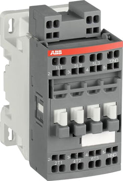
AF09ZB-30-10S-21 24-60V50/60HZ 20-60VDC Contactor
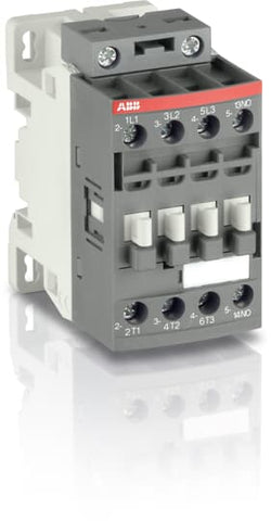
Ordering
1 piece
85364900
Popular Downloads
Dimensions
45 mm
77 mm
86 mm
0.31 kg
Technical
3
0
1
0
3P
IEC/EN 60947-1, IEC/EN 60947-4-1, UL 60335-2-40 LZGH2 A2L, UL 60947-4-1, CSA C22.2 No. 60335-2-40 LZGH2 A2L, CSA C22.2 No. 60947-4-1, IEC 60077-1 (applicable parts), IEC 60077-2 (applicable parts), EN 50155 (applicable parts), TR CU 001/2011, IEC 61373, For compliance confirmation on applicable parts based on your application and combination, please consult your ABB sales representatives.
Auxiliary Circuit 690 V
Main Circuit 690 V
Auxiliary Circuit 690 V
Main Circuit 690 V
Auxiliary Circuit 50 / 60 Hz
Control Circuit 50 / 60 Hz
Main Circuit 50 / 60 Hz
Auxiliary Circuit 50 / 60 Hz
Control Circuit 50 / 60 Hz
Main Circuit 50 / 60 Hz
acc. to IEC 60947-4-1, Open Contactors Θ = 40 °C 35 A
acc. to IEC 60947-5-1, Θ = 40 °C 16 A
acc. to IEC 60947-4-1, Open Contactors Θ = 40 °C 35 A
acc. to IEC 60947-5-1, Θ = 40 °C 16 A
(690 V) 40 °C 25 A
(690 V) 60 °C 25 A
(690 V) 70 °C 22 A
(690 V) 40 °C 25 A
(690 V) 60 °C 25 A
(690 V) 70 °C 22 A
(415 V) 60 °C 9 A
(440 V) 60 °C 9 A
(500 V) 60 °C 9.5 A
(690 V) 60 °C 7 A
(380 / 400 V) 60 °C 9 A
(220 / 230 / 240 V) 60 °C 9 A
(415 V) 60 °C 9 A
(440 V) 60 °C 9 A
(500 V) 60 °C 9.5 A
(690 V) 60 °C 7 A
(380 / 400 V) 60 °C 9 A
(220 / 230 / 240 V) 60 °C 9 A
(415 V) 60 °C 9 A
(440 V) 60 °C 9 A
(500 V) 60 °C 9.5 A
(690 V) 60 °C 7 A
(380 / 400 V) 60 °C 9 A
(220 / 230 / 240 V) 60 °C 9 A
(415 V) 60 °C 9 A
(440 V) 60 °C 9 A
(500 V) 60 °C 9.5 A
(690 V) 60 °C 7 A
(380 / 400 V) 60 °C 9 A
(220 / 230 / 240 V) 60 °C 9 A
(500 V) 2 A
(690 V) 2 A
(24 / 127 V) 6 A
(220 / 240 V) 4 A
(400 / 440 V) 3 A
(500 V) 2 A
(690 V) 2 A
(24 / 127 V) 6 A
(220 / 240 V) 4 A
(400 / 440 V) 3 A
(110 V) 1-Pole, 40 °C 10 A
(110 V) 1-Pole, 60 °C 10 A
(110 V) 1-Pole, 70 °C 10 A
(110 V) 2 Poles in Series, 40 °C 25 A
(110 V) 2 Poles in Series, 60 °C 25 A
(110 V) 2 Poles in Series, 70 °C 22 A
(110 V) 3 Poles in Series, 40 °C 25 A
(110 V) 3 Poles in Series, 60 °C 25 A
(110 V) 3 Poles in Series, 70 °C 22 A
(220 V) 2 Poles in Series, 40 °C 10 A
(220 V) 2 Poles in Series, 60 °C 10 A
(220 V) 2 Poles in Series, 70 °C 10 A
(220 V) 3 Poles in Series, 40 °C 25 A
(220 V) 3 Poles in Series, 60 °C 25 A
(220 V) 3 Poles in Series, 70 °C 22 A
(72 V) 1-Pole, 40 °C 25 A
(72 V) 1-Pole, 60 °C 25 A
(72 V) 1-Pole, 70 °C 22 A
(72 V) 2 Poles in Series, 40 °C 25 A
(72 V) 2 Poles in Series, 60 °C 25 A
(72 V) 2 Poles in Series, 70 °C 22 A
(72 V) 3 Poles in Series, 40 °C 25 A
(72 V) 3 Poles in Series, 60 °C 25 A
(72 V) 3 Poles in Series, 70 °C 22 A
(110 V) 1-Pole, 40 °C 10 A
(110 V) 1-Pole, 60 °C 10 A
(110 V) 1-Pole, 70 °C 10 A
(110 V) 2 Poles in Series, 40 °C 25 A
(110 V) 2 Poles in Series, 60 °C 25 A
(110 V) 2 Poles in Series, 70 °C 22 A
(110 V) 3 Poles in Series, 40 °C 25 A
(110 V) 3 Poles in Series, 60 °C 25 A
(110 V) 3 Poles in Series, 70 °C 22 A
(220 V) 2 Poles in Series, 40 °C 10 A
(110 V) 1-Pole, 40 °C 6 A
(110 V) 1-Pole, 60 °C 6 A
(110 V) 1-Pole, 70 °C 6 A
(110 V) 2 Poles in Series, 40 °C 25 A
(110 V) 2 Poles in Series, 60 °C 25 A
(110 V) 2 Poles in Series, 70 °C 22 A
(110 V) 3 Poles in Series, 40 °C 25 A
(110 V) 3 Poles in Series, 60 °C 25 A
(110 V) 3 Poles in Series, 70 °C 22 A
(220 V) 2 Poles in Series, 40 °C 6 A
(220 V) 2 Poles in Series, 60 °C 6 A
(220 V) 2 Poles in Series, 70 °C 6 A
(220 V) 3 Poles in Series, 40 °C 25 A
(220 V) 3 Poles in Series, 60 °C 25 A
(220 V) 3 Poles in Series, 70 °C 22 A
(72 V) 1-Pole, 40 °C 25 A
(72 V) 1-Pole, 60 °C 25 A
(72 V) 1-Pole, 70 °C 22 A
(72 V) 2 Poles in Series, 40 °C 25 A
(72 V) 2 Poles in Series, 60 °C 25 A
(72 V) 2 Poles in Series, 70 °C 22 A
(72 V) 3 Poles in Series, 40 °C 25 A
(72 V) 3 Poles in Series, 60 °C 25 A
(72 V) 3 Poles in Series, 70 °C 22 A
(110 V) 1-Pole, 40 °C 6 A
(110 V) 1-Pole, 60 °C 6 A
(110 V) 1-Pole, 70 °C 6 A
(110 V) 2 Poles in Series, 40 °C 25 A
(110 V) 2 Poles in Series, 60 °C 25 A
(110 V) 2 Poles in Series, 70 °C 22 A
(110 V) 3 Poles in Series, 40 °C 25 A
(110 V) 3 Poles in Series, 60 °C 25 A
(110 V) 3 Poles in Series, 70 °C 22 A
(220 V) 2 Poles in Series, 40 °C 6 A
(110 V) 1-Pole, 40 °C 4 A
(110 V) 1-Pole, 60 °C 4 A
(110 V) 1-Pole, 70 °C 4 A
(110 V) 2 Poles in Series, 40 °C 10 A
(110 V) 2 Poles in Series, 60 °C 10 A
(110 V) 2 Poles in Series, 70 °C 10 A
(110 V) 3 Poles in Series, 40 °C 25 A
(110 V) 3 Poles in Series, 60 °C 25 A
(110 V) 3 Poles in Series, 70 °C 22 A
(220 V) 2 Poles in Series, 40 °C 4 A
(220 V) 2 Poles in Series, 60 °C 4 A
(220 V) 2 Poles in Series, 70 °C 4 A
(220 V) 3 Poles in Series, 40 °C 9 A
(220 V) 3 Poles in Series, 60 °C 9 A
(220 V) 3 Poles in Series, 70 °C 9 A
(72 V) 1-Pole, 40 °C 9 A
(72 V) 1-Pole, 60 °C 9 A
(72 V) 1-Pole, 70 °C 9 A
(72 V) 2 Poles in Series, 40 °C 25 A
(72 V) 2 Poles in Series, 60 °C 25 A
(72 V) 2 Poles in Series, 70 °C 22 A
(72 V) 3 Poles in Series, 40 °C 25 A
(72 V) 3 Poles in Series, 60 °C 25 A
(72 V) 3 Poles in Series, 70 °C 22 A
(110 V) 1-Pole, 40 °C 4 A
(110 V) 1-Pole, 60 °C 4 A
(110 V) 1-Pole, 70 °C 4 A
(110 V) 2 Poles in Series, 40 °C 10 A
(110 V) 2 Poles in Series, 60 °C 10 A
(110 V) 2 Poles in Series, 70 °C 10 A
(110 V) 3 Poles in Series, 40 °C 25 A
(110 V) 3 Poles in Series, 60 °C 25 A
(110 V) 3 Poles in Series, 70 °C 22 A
(220 V) 2 Poles in Series, 40 °C 4 A
(24 V) 6 A / 144 W
(48 V) 2.8 A / 134 W
(72 V) 1 A / 72 W
(110 V) 0.55 A / 60 W
(125 V) 0.55 A / 69 W
(220 V) 0.27 A / 60 W
(250 V) 0.27 A / 68 W
(400 V) 0.15 A / 60 W
(500 V) 0.13 A / 65 W
(600 V) 0.1 A / 60 W
(24 V) 6 A / 144 W
(48 V) 2.8 A / 134 W
(72 V) 1 A / 72 W
(110 V) 0.55 A / 60 W
(125 V) 0.55 A / 69 W
(220 V) 0.27 A / 60 W
(250 V) 0.27 A / 68 W
(400 V) 0.15 A / 60 W
(500 V) 0.13 A / 65 W
(600 V) 0.1 A / 60 W
(415 V) 4 kW
(440 V) 4 kW
(500 V) 5.5 kW
(690 V) 5.5 kW
(380 / 400 V) 4 kW
(220 / 230 / 240 V) 2.2 kW
(415 V) 4 kW
(440 V) 4 kW
(500 V) 5.5 kW
(690 V) 5.5 kW
(380 / 400 V) 4 kW
(220 / 230 / 240 V) 2.2 kW
(415 V) 4 kW
(440 V) 4 kW
(500 V) 5.5 kW
(690 V) 5.5 kW
(380 / 400 V) 4 kW
(220 / 230 / 240 V) 2.2 kW
(415 V) 4 kW
(440 V) 4 kW
(500 V) 5.5 kW
(690 V) 5.5 kW
(380 / 400 V) 4 kW
(220 / 230 / 240 V) 2.2 kW
at 40 °C Ambient Temp, in Free Air, from a Cold State 10 s 150 A
at 40 °C Ambient Temp, in Free Air, from a Cold State 15 min 35 A
at 40 °C Ambient Temp, in Free Air, from a Cold State 1 min 60 A
at 40 °C Ambient Temp, in Free Air, from a Cold State 1 s 300 A
at 40 °C Ambient Temp, in Free Air, from a Cold State 30 s 80 A
for 0.1 s 140 A
for 1 s 100 A
at 40 °C Ambient Temp, in Free Air, from a Cold State 10 s 150 A
at 40 °C Ambient Temp, in Free Air, from a Cold State 15 min 35 A
at 40 °C Ambient Temp, in Free Air, from a Cold State 1 min 60 A
at 40 °C Ambient Temp, in Free Air, from a Cold State 1 s 300 A
at 40 °C Ambient Temp, in Free Air, from a Cold State 30 s 80 A
for 0.1 s 140 A
for 1 s 100 A
cos phi=0.45 (cos phi=0.35 for Ie > 100 A) at 440 V 250 A
cos phi=0.45 (cos phi=0.35 for Ie > 100 A) at 690 V 106 A
cos phi=0.45 (cos phi=0.35 for Ie > 100 A) at 440 V 250 A
cos phi=0.45 (cos phi=0.35 for Ie > 100 A) at 690 V 106 A
acc. to IEC 60947-4-1 690 V
acc. to IEC 60947-5-1 690 V
acc. to UL/CSA 600 V
acc. to IEC 60947-4-1 690 V
acc. to IEC 60947-5-1 690 V
acc. to UL/CSA 600 V
6 kV
(AC-1) 600 cycles per hour
(AC-15) 1200 cycles per hour
(AC-2 / AC-4) 300 cycles per hour
(AC-3) 1200 cycles per hour
(DC-13) 900 cycles per hour
(AC-1) 600 cycles per hour
(AC-15) 1200 cycles per hour
(AC-2 / AC-4) 300 cycles per hour
(AC-3) 1200 cycles per hour
(DC-13) 900 cycles per hour
3600 cycles per hour
50 Hz 24 ... 60 V
60 Hz 24 ... 60 V
DC Operation 20 ... 60 V
50 Hz 24 ... 60 V
60 Hz 24 ... 60 V
DC Operation 20 ... 60 V
at 6 A per Pole 0.1 W
at Rated Operating Conditions AC-1 per Pole 0.8 W
at Rated Operating Conditions AC-3 per Pole 0.1 W
at 6 A per Pole 0.1 W
at Rated Operating Conditions AC-1 per Pole 0.8 W
at Rated Operating Conditions AC-3 per Pole 0.1 W
Between Coil De-energization and NC Contact Closing 13 ... 98 ms
Between Coil De-energization and NO Contact Opening 11 ... 95 ms
Between Coil Energization and NC Contact Opening 38 ... 90 ms
Between Coil Energization and NO Contact Closing 40 ... 95 ms
Between Coil De-energization and NC Contact Closing 13 ... 98 ms
Between Coil De-energization and NO Contact Opening 11 ... 95 ms
Between Coil Energization and NC Contact Opening 38 ... 90 ms
Between Coil Energization and NO Contact Closing 40 ... 95 ms
TH35-15 (35 x 15 mm Mounting Rail) acc. to IEC 60715
TH35-7.5 (35 x 7.5 mm Mounting Rail) acc. to IEC 60715
TH35-15 (35 x 15 mm Mounting Rail) acc. to IEC 60715
TH35-7.5 (35 x 7.5 mm Mounting Rail) acc. to IEC 60715
2 x M4 Screws Placed Diagonally
Flexible with Ferrule 1/2x 0.75 ... 6 mm²
Flexible with Insulated Ferrule 1x 0.75 ... 4 mm²
Flexible with Insulated Ferrule 2x 0.75 ... 2.5 mm²
Rigid Solid 1/2x 1 ... 4 mm²
Rigid Stranded 1/2x 1 ... 6 mm²
Flexible with Ferrule 1/2x 0.75 ... 6 mm²
Flexible with Insulated Ferrule 1x 0.75 ... 4 mm²
Flexible with Insulated Ferrule 2x 0.75 ... 2.5 mm²
Rigid Solid 1/2x 1 ... 4 mm²
Rigid Stranded 1/2x 1 ... 6 mm²
Rigid Solid 1/2x 1 ... 2.5 mm²
Rigid Stranded 1/2x 1 ... 2.5 mm²
Rigid Solid 1/2x 1 ... 2.5 mm²
Rigid Stranded 1/2x 1 ... 2.5 mm²
Flexible with Ferrule 1/2x 0.75 ... 2.5 mm²
Flexible with Insulated Ferrule 1x 0.75 ... 2.5 mm²
Flexible with Insulated Ferrule 2x 0.75 ... 1.5 mm²
Rigid Solid 1/2x 1 ... 2.5 mm²
Rigid Stranded 1/2x 1 ... 2.5 mm²
Flexible with Ferrule 1/2x 0.75 ... 2.5 mm²
Flexible with Insulated Ferrule 1x 0.75 ... 2.5 mm²
Flexible with Insulated Ferrule 2x 0.75 ... 1.5 mm²
Rigid Solid 1/2x 1 ... 2.5 mm²
Rigid Stranded 1/2x 1 ... 2.5 mm²
Auxiliary Circuit 10 mm
Control Circuit 10 mm
Main Circuit 10 mm
Auxiliary Circuit 10 mm
Control Circuit 10 mm
Main Circuit 10 mm
acc. to IEC 60529, IEC 60947-1, EN 60529 Auxiliary Terminals IP20
acc. to IEC 60529, IEC 60947-1, EN 60529 Coil Terminals IP20
acc. to IEC 60529, IEC 60947-1, EN 60529 Main Terminals IP20
acc. to IEC 60529, IEC 60947-1, EN 60529 Auxiliary Terminals IP20
acc. to IEC 60529, IEC 60947-1, EN 60529 Coil Terminals IP20
acc. to IEC 60529, IEC 60947-1, EN 60529 Main Terminals IP20
Auxiliary Circuit 1.2 N·m
Control Circuit 1.2 N·m
Main Circuit 1.5 N·m
Auxiliary Circuit 1.2 N·m
Control Circuit 1.2 N·m
Main Circuit 1.5 N·m
Screw Terminals
Block Contactor
Technical UL/CSA
00
9 A
(115 V AC) Single Phase 1/3 Hp
(200 V AC) Three Phase 1-1/2 Hp
(230 V AC) Single Phase 1 Hp
(230 V AC) Three Phase 1-1/2 Hp
(460 V AC) Three Phase 2 Hp
(575 V AC) Three Phase 2 Hp
(115 V AC) Single Phase 1/3 Hp
(200 V AC) Three Phase 1-1/2 Hp
(230 V AC) Single Phase 1 Hp
(230 V AC) Three Phase 1-1/2 Hp
(460 V AC) Three Phase 2 Hp
(575 V AC) Three Phase 2 Hp
Main Circuit 600 V
(600 V AC) 25 A
(120 V AC) Single Phase 3/4 hp
(200 ... 208 V AC) Three Phase 2 hp
(220 ... 240 V AC) Three Phase 2 hp
(240 V AC) Single Phase 1-1/2 hp
(440 ... 480 V AC) Three Phase 5 hp
(550 ... 600 V AC) Three Phase 7-1/2 hp
(120 V AC) Single Phase 3/4 hp
(200 ... 208 V AC) Three Phase 2 hp
(220 ... 240 V AC) Three Phase 2 hp
(240 V AC) Single Phase 1-1/2 hp
(440 ... 480 V AC) Three Phase 5 hp
(550 ... 600 V AC) Three Phase 7-1/2 hp
Rigid Solid 1/2x 16-10 AWG
Rigid Stranded 1/2x 16-10 AWG
Rigid Solid 1/2x 16-10 AWG
Rigid Stranded 1/2x 16-10 AWG
Rigid Solid 1/2x 18-14 AWG
Rigid Stranded 1/2x 18-14 AWG
Rigid Solid 1/2x 18-14 AWG
Rigid Stranded 1/2x 18-14 AWG
Rigid Solid 1/2x 18-14 AWG
Rigid Stranded 1/2x 18-14 AWG
Rigid Solid 1/2x 18-14 AWG
Rigid Stranded 1/2x 18-14 AWG
Auxiliary Circuit 11 in·lb
Control Circuit 11 in·lb
Main Circuit 13 in·lb
Auxiliary Circuit 11 in·lb
Control Circuit 11 in·lb
Main Circuit 13 in·lb
(120 V AC) Single Phase 13.8 A
(200 ... 208 V AC) Three Phase 7.8 A
(220 ... 240 V AC) Three Phase 6.8 A
(240 V AC) Single Phase 10 A
(440 ... 480 V AC) Three Phase 7.6 A
(550 ... 600 V AC) Three Phase 9 A
(120 V AC) Single Phase 13.8 A
(200 ... 208 V AC) Three Phase 7.8 A
(220 ... 240 V AC) Three Phase 6.8 A
(240 V AC) Single Phase 10 A
(440 ... 480 V AC) Three Phase 7.6 A
(550 ... 600 V AC) Three Phase 9 A
Environmental
Close to Contactor Fitted with Thermal O/L Relay -25 ... 60 °C
Close to Contactor without Thermal O/L Relay -40 ... 70 °C
Close to Contactor for Storage -60 ... +80 °C
Close to Contactor Fitted with Thermal O/L Relay -25 ... 60 °C
Close to Contactor without Thermal O/L Relay -40 ... 70 °C
Close to Contactor for Storage -60 ... +80 °C
Category B according to IEC 60947-1 Annex Q
Without Derating 3000 m
Category 1, Class B
3
Material Compliance
Following EU Directive 2011/65/EU and Amendment 2015/863 July 22, 2019
0e2ffedb-f43b-40b8-9791-a600bb7283e4 China
Business To Business
5. Small Equipment (No External Dimension More Than 50 cm)
ABB EcoSolutions
Recycled Cardboard - 86 %
Recycled Metal - 28 %
Certificates and Declarations
Container Information
box 1 piece
87 mm
79 mm
47 mm
0.31 kg
3471523123519
box 27 piece
250 mm
300 mm
315 mm
16.74 kg
External Classifications and Standards
Q
EC000066 - Power contactor, AC switching
EC000066 - Power contactor, AC switching
EC000066 - Power contactor, AC switching
V11.0 : 27371003
39121529
4758 >> Iec Contactors