
 1 year warranty

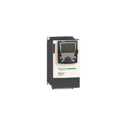
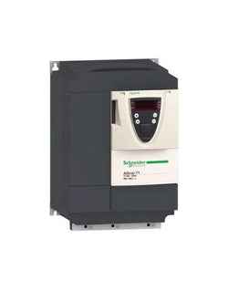
Variable Speed Drive Altivar 71 - 0.75kW-1hp - 480V - with EMC filter and Graphic Terminal
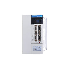
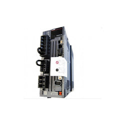
SERVO AMPLIFIER, 3.5 KW, SSCNET BUS CONTROL, 200-230 VAC, 3 PHASE, 16 AMP
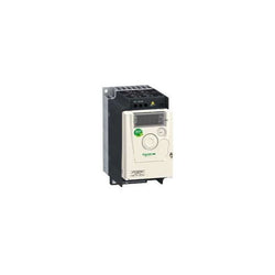
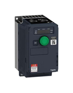
This Altivar 312 single phase variable speed drive has a rated power of 1.5kW, 3.2kVA, and a 200V to 240V AC rated output voltage. It is suitable for industrial machines such as materials handling and packaging, packing, textile machines, special machines, pumps and fans. It has a compact form-factor with 105mm width, allowing for a flexible and easy installation on a mounting plate. It also offers a snap-lock seal, status and faults display, a jog dial navigation button and an integrated EMC filter. It offers high readability of key parameters thanks to a bright LED 4-digit display. SoMove software compatibility enables saving and transfering of configurations to spare drive, reducing maintenance downtime.
Main
| Characteristic | Value(s) |
|---|---|
| Range of Product | Altivar 312 |
| Product or Component Type | Variable speed drive |
| Product destination | Asynchronous motors |
| Product Specific Application | Simple machine |
| Assembly style | With heat sink |
| Component name | ATV312 |
| Motor power kW | 1.5 kW |
| Maximum Horse Power Rating | 2 hp |
| [Us] rated supply voltage | 200...240 V - 15...10 % |
| Supply frequency | 50...60 Hz - 5...5 % |
| Phase | Single phase |
| Line current | 15.8 A 200 V, Isc = 1 kA 13.3 A 240 V |
| EMC filter | Integrated |
| Apparent power | 3.2 kVA |
| Maximum transient current | 12 A 60 s |
| Power dissipation in W | 90 W at nominal load |
| Speed range | 1â¦50 |
| Asynchronous motor control profile | Sensorless flux vector control with PWM type motor control signal Factory set : constant torque |
| Electrical connection | Al1, Al2, Al3, AOV, AOC, R1A, R1B, R1C, R2A, R2B, LI1...LI6 terminal 0.004 in² (2.5 mm²) AWG 14 L1, L2, L3, U, V, W, PA, PB, PA/+, PC/- terminal 0.008 in² (5 mm²) AWG 10 |
| Supply | Internal supply for logic inputs 19...30 V 100 mA overload and short-circuit protection Internal supply for reference potentiometer (2.2 to 10 kOhm) 10...10.8 V 10 mA overload and short-circuit protection |
| Communication Port Protocol | CANopen Modbus |
| IP degree of protection | IP20 on upper part without cover plate IP21 on connection terminals IP31 on upper part IP41 on upper part |
| Option card | Communication card CANopen daisy chain Communication card DeviceNet Communication card Fipio Communication card Modbus TCP Communication card Profibus DP |
Complementary
| Characteristic | Value(s) |
|---|---|
| Supply voltage limits | 170â¦264 V |
| Prospective line Isc | 1 kA |
| Continuous output current | 8 A 4 kHz |
| Output frequency | 0â¦500 Hz |
| Nominal switching frequency | 4 kHz |
| Switching frequency | 2...16 kHz adjustable |
| Transient overtorque | 170â¦200 % of nominal motor torque |
| Braking torque | 150 % 60 s with braking resistor 100 % with braking resistor continuously 150 % without braking resistor |
| Regulation loop | Frequency PI regulator |
| Motor slip compensation | Automatic whatever the load Adjustable Suppressable |
| Output voltage | <= power supply voltage |
| Tightening torque | Al1, Al2, Al3, AOV, AOC, R1A, R1B, R1C, R2A, R2B, LI1...LI6 5.3 lbf.in (0.6 N.m) L1, L2, L3, U, V, W, PA, PB, PA/+, PC/- 10.6 lbf.in (1.2 N.m) |
| Insulation | Electrical between power and control |
| Analogue input number | 3 |
| Analogue input type | AI1 configurable voltage 0...10 V 30 V max 30000 Ohm AI2 configurable voltage +/- 10 V 30 V max 30000 Ohm AI3 configurable current 0...20 mA 250 Ohm |
| Sampling duration | AI1, AI2, AI3 8 ms analog LI1...LI6 4 ms discrete |
| Response time | AOV, AOC 8 ms analog R1A, R1B, R1C, R2A, R2B 8 ms discrete |
| Linearity error | +/- 0.2 % output |
| Analogue output number | 1 |
| Analogue output type | AOC configurable current 0...20 mA 800 Ohm 8 bits AOV configurable voltage 0...10 V 470 Ohm 8 bits |
| Discrete input logic | Logic input not wired LI1...LI4), < 13 V Negative logic (source) LI1...LI6), > 19 V Positive logic (source) LI1...LI6), < 5 V, > 11 V |
| Discrete output number | 2 |
| Discrete output type | Configurable relay logic R1A, R1B, R1C) 1 NO + 1 NC - 100000 cycles Configurable relay logic R2A, R2B) NC - 100000 cycles |
| Minimum switching current | R1-R2 10 mA 5 V DC |
| Maximum switching current | R1-R2 2 A 250 V AC inductive, cos phi = 0.4 7 ms R1-R2 2 A 30 V DC inductive, cos phi = 0.4 7 ms R1-R2 5 A 250 V AC resistive, cos phi = 1 0 ms R1-R2 5 A 30 V DC resistive, cos phi = 1 0 ms |
| Discrete input number | 6 |
| Discrete input type | LI1...LI6) programmable 24 V, 0â¦100 mA PLC 3500 Ohm |
| Acceleration and deceleration ramps | S, U or customized Linear adjustable separately from 0.1 to 999.9 s |
| Braking to standstill | By DC injection |
| Protection type | Input phase breaks drive Line supply overvoltage and undervoltage safety circuits drive Line supply phase loss safety function, for three phases supply drive Motor phase breaks drive Overcurrent between output phases and earth (on power up only) drive Overheating protection drive Short-circuit between motor phases drive Thermal protection motor |
| Insulation resistance | >= 500 mOhm 500 V DC for 1 minute |
| Local signalling | 1 LED (red) for drive voltage Four 7-segment display units for CANopen bus status |
| Time constant | 5 ms for reference change |
| Frequency resolution | Analog input 0.1...100 Hz Display unit 0.1 Hz |
| Connector type | 1 RJ45 Modbus/CANopen |
| Physical interface | RS485 multidrop serial link |
| Transmission frame | RTU |
| Transmission Rate | 10, 20, 50, 125, 250, 500 kbps or 1 Mbps CANopen 4800, 9600 or 19200 bps Modbus |
| Number of addresses | 1â¦127 CANopen 1â¦247 Modbus |
| Number of drive | 127 CANopen 31 Modbus |
| Marking | CE |
| Operating position | Vertical +/- 10 degree |
| Outer dimension | 184 x 149 x 145 mm 200 x 180 x 144 mm 143 x 105 x 150 mm |
| Height | 5.6 in (143 mm) |
| Width | 4.2 in (107 mm) |
| Depth | 6.0 in (152 mm) |
| Product Weight | 4.0 lb(US) (1.8 kg) |

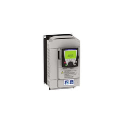
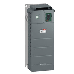
This Altivar 212 variable speed drive can feed 3-phase asynchronous motors. Its protection index is IP21 and it has a built-in EMC filter. It works at a rated power up to 75kW / 100hp and a rated voltage from 380V to 480V AC. Its design is based on eco-energy with a reduction in energy consumption of up to 70% compared to a conventional control system. Thanks to its cable temperature rise reduction technology, the Altivar 212 drive offers immediate, disturbance-free operation avoiding additional options such as a line choke or DC choke to deal with current harmonics. It weighs 55.4kg and its dimensions are, 320mm wide, 630mm high, 290mm deep. It is specifically designed for the most common fluid management applications in tertiary sector buildings (HVAC) like heating, ventilation, air conditioning and pumping. It conforms to international standards IEC/EN 61800-5-1 and IEC/EN 61800-3 (immunity and conducted and radiated EMC emissions). It is also CE, UL, CSA, C-Tick and NOM certified. The Altivar 212 offers optional motor chokes which can increase the maximum cable lengths between the drive and the motor and limit disturbance at the motor terminals. It is designed to be mounted in vertical position (+/- 10 °) on a panel, thanks to 4 fixing holes. The Altivar 212 drive can easily be adapted to all building management systems thanks to its numerous functions and communication protocols integrated as standard, Modbus, METASYS N2, APOGEE FLN P1 and BACnet.
Main
| Characteristic | Value(s) |
|---|---|
| Device short name | ATV212 |
| Product destination | Asynchronous motors |
| Phase | 3 phase |
| Motor power kW | 75 kW |
| Maximum Horse Power Rating | 100 hp |
| Supply voltage limits | 323â¦528 V |
| Supply frequency | 50...60 Hz - 5...5 % |
| Line current | 141.8 A 380 V 111.3 A 480 V |
| Range of Product | Altivar 212 |
| Product or Component Type | Variable speed drive |
| Product Specific Application | Pumps and fans in HVAC |
| Communication Port Protocol | METASYS N2 Modbus APOGEE FLN BACnet LonWorks |
| [Us] rated supply voltage | 380...480 V - 15...10 % |
| EMC filter | Class C2 EMC filter integrated |
| IP degree of protection | IP21 |
Complementary
| Characteristic | Value(s) |
|---|---|
| Apparent power | 105.3 kVA 380 V |
| Continuous output current | 160 A 380 V 160 A 460 V |
| Maximum transient current | 176 A 60 s |
| Speed drive output frequency | 0.5â¦200 Hz |
| Speed range | 1â¦10 |
| Speed accuracy | +/- 10 % of nominal slip 0.2 Tn to Tn |
| Local signalling | 1 LED (red) for DC bus energized |
| Output voltage | <= power supply voltage |
| Isolation | Electrical between power and control |
| Type of cable | Without mounting kit 1 IEC cable 113 °F (45 °C), copper 90 °C / XLPE/EPR Without mounting kit 1 IEC cable 113 °F (45 °C), copper 70 °C / PVC With UL Type 1 kit 3 UL 508 cable 104 °F (40 °C), copper 75 °C / PVC |
| Electrical connection | VIA, VIB, FM, FLA, FLB, FLC, RY, RC, F, R, RES terminal 0.004 in² (2.5 mm²) / AWG 14 L1/R, L2/S, L3/T terminal 0.2 in² (150 mm²) 300 kcmil) |
| Tightening torque | 5.3 lbf.in (0.6 N.m) VIA, VIB, FM, FLA, FLB, FLC, RY, RC, F, R, RES) 362.9 lbf.in (41 N.m), 360 lb.in L1/R, L2/S, L3/T) |
| Supply | Internal supply for reference potentiometer (1 to 10 kOhm) 10.5 V DC +/- 5 %, <10 A overload and short-circuit protection Internal supply 24 V DC 21â¦27 V), <200 A overload and short-circuit protection |
| Sampling duration | 2 ms +/- 0.5 ms F discrete 2 ms +/- 0.5 ms R discrete 2 ms +/- 0.5 ms RES discrete 3.5 ms +/- 0.5 ms VIA analog 22 ms +/- 0.5 ms VIB analog |
| Response time | FM 2 ms +/- 0.5 ms analog FLA, FLC 7 ms +/- 0.5 ms discrete FLB, FLC 7 ms +/- 0.5 ms discrete RY, RC 7 ms +/- 0.5 ms discrete |
| Accuracy | +/- 0.6 % VIA) for a temperature variation 60 °C +/- 0.6 % VIB) for a temperature variation 60 °C +/- 1 % FM) for a temperature variation 60 °C |
| Linearity error | VIA +/- 0.15 % of maximum value input VIB +/- 0.15 % of maximum value input FM +/- 0.2 % output |
| Analogue output type | FM switch-configurable voltage 0...10 V DC 7620 Ohm 10 bits FM switch-configurable current 0...20 mA 970 Ohm 10 bits |
| Discrete output type | Configurable relay logic FLA, FLC) NO - 100000 cycles Configurable relay logic FLB, FLC) NC - 100000 cycles Configurable relay logic RY, RC) NO - 100000 cycles |
| Minimum switching current | 3 mA 24 V DC configurable relay logic |
| Maximum switching current | 5 A 250 V AC resistive cos phi = 1 L/R = 0 ms FL, R) 5 A 30 V DC resistive cos phi = 1 L/R = 0 ms FL, R) 2 A 250 V AC inductive cos phi = 0.4 L/R = 7 ms FL, R) 2 A 30 V DC inductive cos phi = 0.4 L/R = 7 ms FL, R) |
| Discrete input type | F programmable 24 V DC level 1 PLC 4700 Ohm R programmable 24 V DC level 1 PLC 4700 Ohm RES programmable 24 V DC level 1 PLC 4700 Ohm |
| Discrete input logic | Positive logic (source) F, R, RES), <= 5 V, >= 11 V Negative logic (sink) F, R, RES), >= 16 V, <= 10 V |
| Dielectric strength | 3535 V DC between earth and power terminals 5092 V DC between control and power terminals |
| Insulation resistance | >= 1 mOhm 500 V DC for 1 minute |
| Frequency resolution | Display unit 0.1 Hz Analog input 0.024/50 Hz |
| Communication Service | Read device identification (43) Write single register (06) Time out setting from 0.1 to 100 s Monitoring inhibitable Read holding registers (03) 2 words maximum Write multiple registers (16) 2 words maximum |
| Option card | Communication card LonWorks |
| Power dissipation in W | 1945 W |
| air flow | 175941.7 Gal/hr(US) (666 m3/h) |
| Functionality | Mid |
| Specific application | HVAC |
| Variable speed drive application selection | Building - HVAC compressor for scroll Building - HVAC fan Building - HVAC pump |
| Motor power range AC-3 | 55â¦100 kW 380â¦440 V 3 phase 55â¦100 kW 480â¦500 V 3 phase |
| Motor starter type | Variable speed drive |
| Discrete output number | 2 |
| Analogue input number | 2 |
| Analogue input type | VIA switch-configurable voltage 0...10 V DC 24 V max 30000 Ohm 10 bits VIB configurable voltage 0...10 V DC 24 V max 30000 Ohm 10 bits VIB configurable PTC probe 0...6 probes 1500 Ohm VIA switch-configurable current 0...20 mA 250 Ohm 10 bits |
| Analogue output number | 1 |
| Physical interface | 2-wire RS 485 |
| Connector Type | 1 open style 1 RJ45 |
| Transmission Rate | 9600 bps or 19200 bps |
| Transmission frame | RTU |
| Number of addresses | 1â¦247 |
| Data format | 8 bits, 1 stop, odd even or no configurable parity |
| Type of polarization | No impedance |
| Asynchronous motor control profile | Voltage/frequency ratio, 5 points Voltage/frequency ratio - Energy Saving, quadratic U/f Voltage/frequency ratio, automatic IR compensation (U/f + automatic Uo) Voltage/frequency ratio, 2 points Flux vector control without sensor, standard |
| Torque accuracy | +/- 15 % |
| Transient overtorque | 120 % of nominal motor torque +/- 10 % 60 s |
| Acceleration and deceleration ramps | Automatic based on the load Linear adjustable separately from 0.01 to 3200 s |
| Motor slip compensation | Not available in voltage/frequency ratio motor control Automatic whatever the load Adjustable |
| Switching frequency | 6...16 kHz adjustable 8...16 kHz with derating factor |
| Nominal switching frequency | 8 kHz |
| Braking to standstill | By DC injection |
| Network Frequency | 47.5...63 Hz |
| Prospective line Isc | 22 kA |
| Protection type | Overheating protection drive Thermal power stage drive Short-circuit between motor phases drive Input phase breaks drive Overcurrent between output phases and earth drive Overvoltages on the DC bus drive Break on the control circuit drive Against exceeding limit speed drive Line supply overvoltage and undervoltage drive Line supply undervoltage drive Against input phase loss drive Thermal protection motor Motor phase break motor With PTC probes motor |
| Width | 12.6 in (320 mm) |
| Height | 24.8 in (630 mm) |
| Depth | 11.4 in (290 mm) |
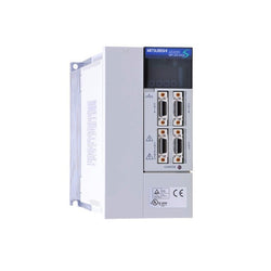
SERVO AC AMPLIFIER, 2000 W INPUT, 10.5 AMP, 200-230V / 50/60 HZ, 2 KW, SERVO AMPLIFIER (DIGITAL OR ANALOGUE CONTROL) (200 V 3-PHASE ONLY)
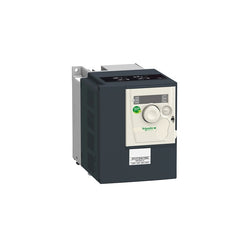
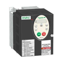
Variable Speed Drive Altivar ATV12 - 0.75kW - 1hp - 200..240V - 3ph - with Heat Sink
Main
| Characteristic | Value(s) |
|---|---|
| Range of Product | Altivar 61 |
| Product or Component Type | Variable speed drive |
| Product Specific Application | Pumping and ventilation machine |
| Component name | ATV61 |
| Motor power kW | 4 kW, 3 phase 380...480 V |
| Maximum Horse Power Rating | 5 hp, 3 phase 380...480 V |
| power supply voltage | 380...480 V - 15...10 % |
| supply number of phases | 3 phase |
| Line current | 11.5 A 480 V 3 phase 4 kW / 5 hp 14.1 A 380 V 3 phase 4 kW / 5 hp |
| EMC filter | Level 3 EMC filter |
| Assembly style | With heat sink |
| Apparent power | 9.3 kVA 380 V 3 phase 4 kW / 5 hp |
| maximum prospective line Isc | 5 kA 3 phase |
| Maximum transient current | 12.6 A 60 s, 3 phase |
| Nominal switching frequency | 12 kHz |
| Switching frequency | 1...16 kHz adjustable 12...16 kHz with derating factor |
| asynchronous motor control | Voltage/frequency ratio, 5 points Voltage/frequency ratio, 2 points Flux vector control without sensor, standard Voltage/frequency ratio - Energy Saving, quadratic U/f |
| Synchronous motor control profile | Vector control without sensor, standard |
| Communication Port Protocol | Modbus CANopen |
| Type of polarization | No impedance Modbus |
| Option card | Communication card APOGEE FLN Communication card BACnet Communication card CC-Link Controller inside programmable card Communication card DeviceNet Communication card EtherNet/IP Communication card Fipio I/O extension card Communication card Interbus-S Communication card LonWorks Communication card METASYS N2 Communication card Modbus Plus Communication card Modbus TCP Communication card Modbus/Uni-Telway Multi-pump card Communication card Profibus DP Communication card Profibus DP V1 |
Complementary
| Characteristic | Value(s) |
|---|---|
| Product destination | Asynchronous motors Synchronous motors |
| power supply voltage limits | 323â¦528 V |
| power supply frequency | 50...60 Hz - 5...5 % |
| power supply frequency limits | 47.5...63 Hz |
| Continuous output current | 7.6 A 12 kHz, 460 V - 3 phase 10.5 A 12 kHz, 380 V - 3 phase |
| Output frequency | 0.1â¦599 Hz |
| Speed range | 1â¦100 in open-loop mode, without speed feedback |
| Speed accuracy | +/- 10 % of nominal slip 0.2 Tn to Tn without speed feedback |
| Torque accuracy | +/- 15 % in open-loop mode, without speed feedback |
| Transient overtorque | 130 % of nominal motor torque +/- 10 % 60 s |
| Braking torque | <= 125 % with braking resistor 30 % without braking resistor |
| Regulation loop | Frequency PI regulator |
| Motor slip compensation | Not available in voltage/frequency ratio (2 or 5 points) Can be suppressed Adjustable Automatic whatever the load |
| diagnostic | 1 LED (red) for drive voltage |
| Output voltage | <= power supply voltage |
| electrical isolation | Between power and control terminals |
| type of cable for mounting in an enclosure | With an IP21 or an IP31 kit 3 IEC cable 104 °F (40 °C), copper 70 °C / PVC With UL Type 1 kit 3 UL 508 cable 104 °F (40 °C), copper 75 °C / PVC Without mounting kit 1 IEC cable 113 °F (45 °C), copper 70 °C / PVC Without mounting kit 1 IEC cable 113 °F (45 °C), copper 90 °C / XLPE/EPR |
| Electrical connection | Terminal 2.5 mm² / AWG 14 AI1-/AI1+, AI2, AO1, R1A, R1B, R1C, R2A, R2B, LI1...LI6, PWR) Terminal 6 mm² / AWG 8 L1/R, L2/S, L3/T, U/T1, V/T2, W/T3, PC/-, PO, PA/+, PA, PB) |
| Tightening torque | 5.3 lbf.in (0.6 N.m) AI1-/AI1+, AI2, AO1, R1A, R1B, R1C, R2A, R2B, LI1...LI6, PWR) 12.4 lbf.in (1.4 N.m), 12.3 lb.in L1/R, L2/S, L3/T, U/T1, V/T2, W/T3, PC/-, PO, PA/+, PA, PB) |
| Supply | Internal supply for reference potentiometer (1 to 10 kOhm) 10.5 V DC, +/- 5 %, <10 mA overload and short-circuit protection Internal supply 24 V DC 21â¦27 V), <200 mA overload and short-circuit protection External supply 24 V DC 19â¦30 V) |
| Analogue input number | 2 |
| Analogue input type | AI1-/Al1+ bipolar differential voltage +/- 10 V DC 24 V max 11 bits + sign AI2 software-configurable current 0...20 mA 242 Ohm 11 bits AI2 software-configurable voltage 0...10 V DC 24 V max 30000 Ohm 11 bits |
| sampling time | 2 ms +/- 0.5 ms AI1-/Al1+) - analog input 2 ms +/- 0.5 ms Al2) - analog input 2 ms +/- 0.5 ms AO1) - analog output 2 ms +/- 0.5 ms LI1...LI5) - discrete input 2 ms +/- 0.5 ms LI6)if configured as logic input - discrete input |
| absolute accuracy precision | +/- 0.6 % AI1-/Al1+) for a temperature variation 60 °C +/- 0.6 % AI2) for a temperature variation 60 °C +/- 1 % AO1) for a temperature variation 60 °C |
| Linearity error | +/- 0.15 % of maximum value AI1-/Al1+) +/- 0.15 % of maximum value AI2) +/- 0.2 % AO1) |
| Analogue output number | 1 |
| Analogue output type | AO1 software-configurable current 0...20 mA 500 Ohm 10 bits AO1 software-configurable voltage 0...10 V DC 470 Ohm 10 bits AO1 software-configurable logic output 10 V, 20 mA |
| Discrete output number | 2 |
| Discrete output type | Configurable relay logic R1A, R1B, R1C) NO/NC - 100000 cycles Configurable relay logic R2A, R2B) NO - 100000 cycles |
| maximum response time | <= 100 ms in STO (Safe Torque Off) R1A, R1B, R1C <= 7 ms +/- 0.5 ms R2A, R2B <= 7 ms +/- 0.5 ms |
| Minimum switching current | 3 mA 24 V DC configurable relay logic |
| Maximum switching current | R1, R2 2 A 250 V AC inductive, cos phi = 0.4 7 ms R1, R2 2 A 30 V DC inductive, cos phi = 0.4 7 ms R1, R2 5 A 250 V AC resistive, cos phi = 1 0 ms R1, R2 5 A 30 V DC resistive, cos phi = 1 0 ms |
| Discrete input number | 7 |
| Discrete input type | Programmable LI1...LI5) 24 V DC <= 30 V)level 1 PLC - 3500 Ohm Switch-configurable LI6) 24 V DC <= 30 V)level 1 PLC - 3500 Ohm Switch-configurable PTC probe LI6)0â¦6 - 1500 Ohm Safety input PWR) 24 V DC <= 30 V) - 1500 Ohm |
| Discrete input logic | Negative logic (sink) LI1...LI5), > 16 V, < 10 V Positive logic (source) LI1...LI5), < 5 V, > 11 V Negative logic (sink) LI6)if configured as logic input, > 16 V, < 10 V Positive logic (source) LI6)if configured as logic input, < 5 V, > 11 V |
| Acceleration and deceleration ramps | Linear adjustable separately from 0.01 to 9000 s Automatic adaptation of ramp if braking capacity exceeded, by using resistor S, U or customized |
| Braking to standstill | By DC injection |
| Protection type | Against exceeding limit speed drive Against input phase loss drive Break on the control circuit drive Input phase breaks drive Line supply overvoltage drive Line supply undervoltage drive Overcurrent between output phases and earth drive Overheating protection drive Overvoltages on the DC bus drive Power removal drive Short-circuit between motor phases drive Thermal protection drive Motor phase break motor Power removal motor Thermal protection motor |
| Insulation resistance | > 1 mOhm 500 V DC for 1 minute to earth |
| Frequency resolution | Analog input 0.024/50 Hz Display unit 0.1 Hz |
| Connector type | 1 RJ45 on front face)Modbus 1 RJ45 on terminal)Modbus Male SUB-D 9 on RJ45CANopen |
| Physical interface | 2-wire RS 485 Modbus |
| Transmission frame | RTU Modbus |
| Transmission rate | 4800 bps, 9600 bps, 19200 bps, 38.4 Kbps Modbus on terminal 9600 bps, 19200 bps Modbus on front face 20 kbps, 50 kbps, 125 kbps, 250 kbps, 500 kbps, 1 Mbps CANopen |
| Data format | 8 bits, 1 stop, even parity Modbus on front face 8 bits, odd even or no configurable parity Modbus on terminal |
| Number of addresses | 1â¦127 CANopen 1â¦247 Modbus |
| Method of access | Slave CANopen |
| Marking | CE |
| Operating position | Vertical +/- 10 degree |
| Product Weight | 8.8 lb(US) (4 kg) |
| Width | 6.1 in (155 mm) |
| Height | 10.2 in (260 mm) |
| Depth | 7.4 in (187 mm) |
Variable Speed Drive Altivar ATV320 - 3kW - 380...500V - 3 Phase - book
Variable Speed Drive - 4kW- 400V - 3 Phases - Altivar ATV340
SERVO AMPLIFIER, 1 KW, 200 V
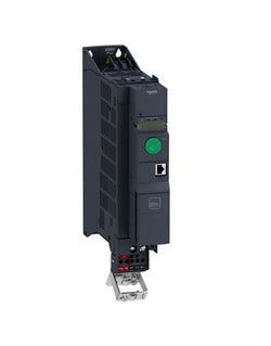
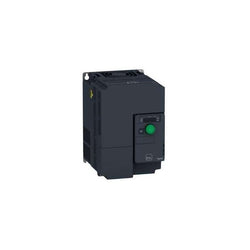
This Altivar 320 variable speed drive can feed three-phase synchronous and asynchronous motors. Its compact form factor allows vertical stacking of drives inside machine frames. It works at a rated power up to 0.18kW / 0.25hp and a rated voltage from 200V to 240V AC. Its robust design with IEC 60721-3-3 class 3C3 coated printed circuit boards allows to extend machine availability in harsh environmental conditions, for example at ambient temperatures of up to 60°C without the need of additional cooling. It incorporates functions suitable for the most common applications, including torque and speed accuracy at very low speed, high dynamic performance with flux vector control without sensor and extended frequency range for high-speed motors. It also incorporates parallel connection of motors and special drives using the voltage/frequency ratio and static speed accuracy and energy saving for open-loop synchronous motors. The drive software includes 5 safety functions that help machines meet safety requirements, whether or not they are used in conjunction with a Preventa safety module. These safety functions are configured using SoMove software. Altivar Machine ATV320 was designed for Original Equipment Manufacturers (OEMs) that meets simple and advanced application requirements covered for packaging, material handling, textile, material working, mechanical actuators and hoisting. It conforms to international standards IEC/EN 61800-5-1 and IEC/EN 61800-3 (immunity and conducted and radiated EMC emissions). It is also CE, UL, CSA, NOM, EAC and RCM certified. Mounting accessories and external options (braking resistors, line chokes, motor chokes, additional EMC filters) are available with Altivar Machine ATV320 drives. The type of external accessories and options depends on the drive rating. It is designed to be mounted in vertical position (+/- 10 °) on a panel, thanks to 4 fixing holes. It is fully integrated inside Schneider Electricâs EcoStruxure Machine through DTM. It is possible to configure, control, and diagnose ATV320 drives directly in SoMachine and SoMove software by means of the same software brick (DTM).
Main
| Characteristic | Value(s) |
|---|---|
| Range of Product | Altivar Machine ATV320 |
| Product or Component Type | Variable speed drive |
| Product Specific Application | Complex machines |
| Variant | Standard version |
| Format of the drive | Compact |
| Mounting Mode | Wall mount |
| Communication Port Protocol | Modbus serial CANopen |
| Option card | communication module, CANopen communication module, EtherCAT communication module, Profibus DP V1 communication module, PROFINET communication module, Ethernet Powerlink communication module, EtherNet/IP communication module, DeviceNet |
| [Us] rated supply voltage | 200...240 V - 15...10 % |
| nominal output current | 1.5 A |
| Motor power kW | 0.18 kW heavy duty |
| EMC filter | Class C2 EMC filter integrated |
| IP degree of protection | IP20 |
Complementary
| Characteristic | Value(s) |
|---|---|
| Discrete input number | 7 |
| Discrete input type | STO safe torque off, 24 V DC1.5 kOhm DI1...DI6 logic inputs, 24 V DC 30 V) DI5 programmable as pulse input 0â¦30 kHz, 24 V DC 30 V) |
| Discrete input logic | Positive logic (source) Negative logic (sink) |
| Discrete output number | 3 |
| Discrete output type | Open collector DQ+ 0â¦1 kHz 30 V DC 100 mA Open collector DQ- 0â¦1 kHz 30 V DC 100 mA |
| Analogue input number | 3 |
| Analogue input type | AI1 voltage 0...10 V DC 30 kOhm 10 bits AI2 bipolar differential voltage +/- 10 V DC 30 kOhm 10 bits AI3 current 0...20 mA (or 4-20 mA, x-20 mA, 20-x mA or other patterns by configuration) 250 Ohm 10 bits |
| Analogue output number | 1 |
| Analogue output type | Software-configurable current AQ1 0...20 mA 800 Ohm 10 bits Software-configurable voltage AQ1 0...10 V DC 470 Ohm 10 bits |
| Relay output type | Configurable relay logic R1A 1 NO 100000 cycles Configurable relay logic R1B 1 NC 100000 cycles Configurable relay logic R1C Configurable relay logic R2A 1 NO 100000 cycles Configurable relay logic R2C |
| Maximum switching current | Relay output R1A, R1B, R1C resistive, cos phi = 1 3 A 250 V AC Relay output R1A, R1B, R1C resistive, cos phi = 1 3 A 30 V DC Relay output R1A, R1B, R1C, R2A, R2C inductive, cos phi = 0.4 7 ms 2 A 250 V AC Relay output R1A, R1B, R1C, R2A, R2C inductive, cos phi = 0.4 7 ms 2 A 30 V DC Relay output R2A, R2C resistive, cos phi = 1 5 A 250 V AC Relay output R2A, R2C resistive, cos phi = 1 5 A 30 V DC |
| Minimum switching current | Relay output R1A, R1B, R1C, R2A, R2C 5 mA 24 V DC |
| Method of access | Slave CANopen |
| 4 quadrant operation possible | True |
| Asynchronous motor control profile | Voltage/frequency ratio, 5 points Flux vector control without sensor, standard Voltage/frequency ratio - Energy Saving, quadratic U/f Flux vector control without sensor - Energy Saving Voltage/frequency ratio, 2 points |
| Synchronous motor control profile | Vector control without sensor |
| Maximum output frequency | 0.599 kHz |
| Acceleration and deceleration ramps | Linear U S CUS Ramp switching Acceleration/deceleration ramp adaptation Acceleration/deceleration automatic stop with DC injection |
| Motor slip compensation | Automatic whatever the load Adjustable 0...300 % Not available in voltage/frequency ratio (2 or 5 points) |
| Switching frequency | 2...16 kHz adjustable 4...16 kHz with derating factor |
| Nominal switching frequency | 4 kHz |
| Braking to standstill | By DC injection |
| Brake chopper integrated | True |
| Line current | 3.4 A 200 V heavy duty) 2.8 A 240 V heavy duty) |
| Maximum Input Current per Phase | 3.4 A |
| Maximum output voltage | 240 V |
| Apparent power | 0.7 kVA 240 V heavy duty) |
| Network Frequency | 50-60 Hz |
| Relative symmetric network frequency tolerance | 5 % |
| Prospective line Isc | 1 kA |
| Base load current at high overload | 6.9 A |
| Power dissipation in W | Self-cooled 17.0 W 200 V 4 kHz |
| With safety function Safely Limited Speed (SLS) | True |
| With safety function Safe brake management (SBC/SBT) | False |
| With safety function Safe Operating Stop (SOS) | False |
| With safety function Safe Position (SP) | False |
| With safety function Safe programmable logic | False |
| With safety function Safe Speed Monitor (SSM) | False |
| With safety function Safe Stop 1 (SS1) | True |
| With sft fct Safe Stop 2 (SS2) | False |
| With safety function Safe torque off (STO) | True |
| With safety function Safely Limited Position (SLP) | False |
| With safety function Safe Direction (SDI) | False |
| Protection type | Input phase breaks drive Overcurrent between output phases and earth drive Overheating protection drive Short-circuit between motor phases drive Thermal protection drive |
| Width | 2.8 in (72.0 mm) |
| Height | 5.6 in (143.0 mm) |
| Depth | 4.3 in (109.0 mm) |
| Product Weight | 1.8 lb(US) (0.8 kg) |
| Transient overtorque | 170â¦200 % of nominal motor torque |
Main
| Characteristic | Value(s) |
|---|---|
| Range of Product | Altivar 61 |
| Product or Component Type | Variable speed drive |
| Product Specific Application | Pumping and ventilation machine |
| Component name | ATV61 |
| Motor power kW | 4 kW, single phase 200...240 V 5.5 kW, 3 phase 200...240 V |
| Maximum Horse Power Rating | 5 hp, single phase 200...240 V 7.5 hp, 3 phase 200...240 V |
| power supply voltage | 200...240 V - 15...10 % |
| supply number of phases | Single phase 3 phase |
| Line current | 29.9 A 240 V single phase 4 kW / 5 hp 30.8 A 240 V 3 phase 5.5 kW / 7.5 hp 34.9 A 200 V single phase 4 kW / 5 hp 35 A 200 V 3 phase 5.5 kW / 7.5 hp |
| EMC filter | Level 3 EMC filter |
| Assembly style | With heat sink |
| Apparent power | 7 kVA 240 V single phase 4 kW / 5 hp 12.8 kVA 240 V 3 phase 5.5 kW / 7.5 hp |
| maximum prospective line Isc | 22 kA 3 phase 5 kA single phase |
| Maximum transient current | 21 A 60 s, single phase 33 A 60 s, 3 phase |
| Nominal switching frequency | 12 kHz |
| Switching frequency | 1...16 kHz adjustable 12...16 kHz with derating factor |
| asynchronous motor control | Voltage/frequency ratio - Energy Saving, quadratic U/f Voltage/frequency ratio, 5 points Flux vector control without sensor, standard Voltage/frequency ratio, 2 points |
| Synchronous motor control profile | Vector control without sensor, standard |
| Communication Port Protocol | Modbus CANopen |
| Type of polarization | No impedance Modbus |
| Option card | Communication card APOGEE FLN Communication card BACnet Communication card CC-Link Controller inside programmable card Communication card DeviceNet Communication card EtherNet/IP Communication card Fipio I/O extension card Communication card Interbus-S Communication card LonWorks Communication card METASYS N2 Communication card Modbus Plus Communication card Modbus TCP Communication card Modbus/Uni-Telway Multi-pump card Communication card Profibus DP Communication card Profibus DP V1 |
Complementary
| Characteristic | Value(s) |
|---|---|
| Product destination | Asynchronous motors Synchronous motors |
| power supply voltage limits | 170â¦264 V |
| power supply frequency | 50...60 Hz - 5...5 % |
| power supply frequency limits | 47.5...63 Hz |
| Continuous output current | 27.5 A 12 kHz, 230 V - 3 phase 17.5 A 12 kHz, 230 V - single phase |
| Output frequency | 0.1â¦599 Hz |
| Speed range | 1â¦100 in open-loop mode, without speed feedback |
| Speed accuracy | +/- 10 % of nominal slip 0.2 Tn to Tn without speed feedback |
| Torque accuracy | +/- 15 % in open-loop mode, without speed feedback |
| Transient overtorque | 130 % of nominal motor torque +/- 10 % 60 s |
| Braking torque | <= 125 % with braking resistor 30 % without braking resistor |
| Regulation loop | Frequency PI regulator |
| Motor slip compensation | Can be suppressed Adjustable Not available in voltage/frequency ratio (2 or 5 points) Automatic whatever the load |
| diagnostic | 1 LED (red) for drive voltage |
| Output voltage | <= power supply voltage |
| electrical isolation | Between power and control terminals |
| type of cable for mounting in an enclosure | With an IP21 or an IP31 kit 3 IEC cable 104 °F (40 °C), copper 70 °C / PVC With UL Type 1 kit 3 UL 508 cable 104 °F (40 °C), copper 75 °C / PVC Without mounting kit 1 IEC cable 113 °F (45 °C), copper 70 °C / PVC Without mounting kit 1 IEC cable 113 °F (45 °C), copper 90 °C / XLPE/EPR |
| Electrical connection | Terminal 2.5 mm² / AWG 14 AI1-/AI1+, AI2, AO1, R1A, R1B, R1C, R2A, R2B, LI1...LI6, PWR) Terminal 6 mm² / AWG 8 L1/R, L2/S, L3/T, U/T1, V/T2, W/T3, PC/-, PO, PA/+, PA, PB) |
| Tightening torque | 5.3 lbf.in (0.6 N.m) AI1-/AI1+, AI2, AO1, R1A, R1B, R1C, R2A, R2B, LI1...LI6, PWR) 26.6 lbf.in (3 N.m), 26.5 lb.in L1/R, L2/S, L3/T, U/T1, V/T2, W/T3, PC/-, PO, PA/+, PA, PB) |
| Supply | Internal supply for reference potentiometer (1 to 10 kOhm) 10.5 V DC, +/- 5 %, <10 mA overload and short-circuit protection Internal supply 24 V DC 21â¦27 V), <200 mA overload and short-circuit protection External supply 24 V DC 19â¦30 V) |
| Analogue input number | 2 |
| Analogue input type | AI1-/Al1+ bipolar differential voltage +/- 10 V DC 24 V max 11 bits + sign AI2 software-configurable current 0...20 mA 242 Ohm 11 bits AI2 software-configurable voltage 0...10 V DC 24 V max 30000 Ohm 11 bits |
| sampling time | 2 ms +/- 0.5 ms AI1-/Al1+) - analog input 2 ms +/- 0.5 ms Al2) - analog input 2 ms +/- 0.5 ms AO1) - analog output 2 ms +/- 0.5 ms LI1...LI5) - discrete input 2 ms +/- 0.5 ms LI6)if configured as logic input - discrete input |
| absolute accuracy precision | +/- 0.6 % AI1-/Al1+) for a temperature variation 60 °C +/- 0.6 % AI2) for a temperature variation 60 °C +/- 1 % AO1) for a temperature variation 60 °C |
| Linearity error | +/- 0.15 % of maximum value AI1-/Al1+) +/- 0.15 % of maximum value AI2) +/- 0.2 % AO1) |
| Analogue output number | 1 |
| Analogue output type | AO1 software-configurable current 0...20 mA 500 Ohm 10 bits AO1 software-configurable voltage 0...10 V DC 470 Ohm 10 bits AO1 software-configurable logic output 10 V, 20 mA |
| Discrete output number | 2 |
| Discrete output type | Configurable relay logic R1A, R1B, R1C) NO/NC - 100000 cycles Configurable relay logic R2A, R2B) NO - 100000 cycles |
| maximum response time | <= 100 ms in STO (Safe Torque Off) R1A, R1B, R1C <= 7 ms +/- 0.5 ms R2A, R2B <= 7 ms +/- 0.5 ms |
| Minimum switching current | 3 mA 24 V DC configurable relay logic |
| Maximum switching current | R1, R2 2 A 250 V AC inductive, cos phi = 0.4 7 ms R1, R2 2 A 30 V DC inductive, cos phi = 0.4 7 ms R1, R2 5 A 250 V AC resistive, cos phi = 1 0 ms R1, R2 5 A 30 V DC resistive, cos phi = 1 0 ms |
| Discrete input number | 7 |
| Discrete input type | Programmable LI1...LI5) 24 V DC <= 30 V)level 1 PLC - 3500 Ohm Switch-configurable LI6) 24 V DC <= 30 V)level 1 PLC - 3500 Ohm Switch-configurable PTC probe LI6)0â¦6 - 1500 Ohm Safety input PWR) 24 V DC <= 30 V) - 1500 Ohm |
| Discrete input logic | Negative logic (sink) LI1...LI5), > 16 V, < 10 V Positive logic (source) LI1...LI5), < 5 V, > 11 V Negative logic (sink) LI6)if configured as logic input, > 16 V, < 10 V Positive logic (source) LI6)if configured as logic input, < 5 V, > 11 V |
| Acceleration and deceleration ramps | S, U or customized Automatic adaptation of ramp if braking capacity exceeded, by using resistor Linear adjustable separately from 0.01 to 9000 s |
| Braking to standstill | By DC injection |
| Protection type | Against exceeding limit speed drive Against input phase loss drive Break on the control circuit drive Input phase breaks drive Line supply overvoltage drive Line supply undervoltage drive Overcurrent between output phases and earth drive Overheating protection drive Overvoltages on the DC bus drive Power removal drive Short-circuit between motor phases drive Thermal protection drive Motor phase break motor Power removal motor Thermal protection motor |
| Insulation resistance | > 1 mOhm 500 V DC for 1 minute to earth |
| Frequency resolution | Analog input 0.024/50 Hz Display unit 0.1 Hz |
| Connector type | 1 RJ45 on front face)Modbus 1 RJ45 on terminal)Modbus Male SUB-D 9 on RJ45CANopen |
| Physical interface | 2-wire RS 485 Modbus |
| Transmission frame | RTU Modbus |
| Transmission rate | 4800 bps, 9600 bps, 19200 bps, 38.4 Kbps Modbus on terminal 9600 bps, 19200 bps Modbus on front face 20 kbps, 50 kbps, 125 kbps, 250 kbps, 500 kbps, 1 Mbps CANopen |
| Data format | 8 bits, 1 stop, even parity Modbus on front face 8 bits, odd even or no configurable parity Modbus on terminal |
| Number of addresses | 1â¦127 CANopen 1â¦247 Modbus |
| Method of access | Slave CANopen |
| Marking | CE |
| Operating position | Vertical +/- 10 degree |
| Product Weight | 12.1 lb(US) (5.5 kg) |
| Width | 6.9 in (175 mm) |
| Height | 11.6 in (295 mm) |
| Depth | 7.4 in (187 mm) |
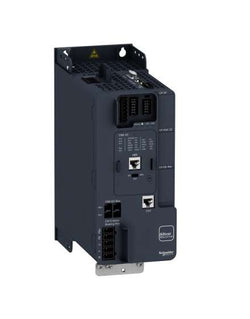
Variable Speed Drive - 7.5kW- 400V - 3 Phases - Altivar ATV340
Main
| Characteristic | Value(s) |
|---|---|
| Range of Product | Altivar 71 |
| Product or Component Type | Variable speed drive |
| Product Specific Application | Complex, high-power machines |
| Component name | ATV71 |
| Motor power kW | 11 kW, 3 phase 380...480 V |
| Maximum Horse Power Rating | 15 hp, 3 phase 380...480 V |
| Maximum motor cable length | 164.04 ft (50 m) shielded cable 328.08 ft (100 m) unshielded cable |
| power supply voltage | 380...480 V - 15...10 % |
| Phase | 3 phase |
| Line current | 30 A 480 V 3 phase 11 kW / 15 hp 36.6 A 380 V 3 phase 11 kW / 15 hp |
| EMC filter | Integrated |
| Assembly style | With heat sink |
| Variant | Without remote graphic terminal |
| Apparent power | 24.1 kVA 380 V 3 phase 11 kW / 15 hp |
| Prospective line Isc | 22 kA 3 phase |
| Nominal output current | 21 A 4 kHz 460 V 3 phase 11 kW / 15 hp 27.7 A 4 kHz 380 V 3 phase 11 kW / 15 hp |
| Maximum transient current | 41.6 A 60 s 3 phase 11 kW / 15 hp 45.7 A 2 s 3 phase 11 kW / 15 hp |
| Output frequency | 0.1â¦599 Hz |
| Nominal switching frequency | 4 kHz |
| Switching frequency | 1...16 kHz adjustable 4...16 kHz with derating factor |
| Asynchronous motor control profile | ENA (Energy adaptation) system for unbalanced loads Sensorless flux vector control (SFVC) (voltage or current vector) Voltage/frequency ratio (2 or 5 points) Flux vector control (FVC) with sensor (current vector) |
| Type of polarization | No impedance Modbus |
Complementary
| Characteristic | Value(s) |
|---|---|
| Product destination | Asynchronous motors Synchronous motors |
| power supply voltage limits | 323â¦528 V |
| power supply frequency | 50...60 Hz - 5...5 % |
| power supply frequency limits | 47.5...63 Hz |
| Speed range | 1â¦100 asynchronous motor in open-loop mode, without speed feedback 1â¦1000 asynchronous motor in closed-loop mode with encoder feedback 1â¦50 synchronous motor in open-loop mode, without speed feedback |
| Speed accuracy | +/- 0.01 % of nominal speed in closed-loop mode with encoder feedback 0.2 Tn to Tn +/- 10 % of nominal slip without speed feedback 0.2 Tn to Tn |
| Torque accuracy | +/- 15 % in open-loop mode, without speed feedback +/- 5 % in closed-loop mode with encoder feedback |
| Transient overtorque | 170 % +/- 10 % 60 s every 10 minutes 220 % +/- 10 % 2 s |
| Braking torque | <= 150 % with braking or hoist resistor 30 % without braking resistor |
| Synchronous motor control profile | Vector control without speed feedback |
| Regulation loop | Adjustable PI regulator |
| Motor slip compensation | Adjustable Not available in voltage/frequency ratio (2 or 5 points) Automatic whatever the load Suppressable |
| diagnostic | 1 LED (red) for drive voltage |
| Output voltage | <= power supply voltage |
| Insulation | Electrical between power and control |
| type of cable for mounting in an enclosure | With a NEMA Type1 kit 3 UL 508 cable 104 °F (40 °C), copper 75 °C / PVC With an IP21 or an IP31 kit 3 IEC cable 104 °F (40 °C), copper 70 °C / PVC Without mounting kit 1 IEC cable 113 °F (45 °C), copper 70 °C / PVC Without mounting kit 1 IEC cable 113 °F (45 °C), copper 90 °C / XLPE/EPR |
| Electrical connection | Terminal 2.5 mm², AWG 14 AI1-/AI1+, AI2, AO1, R1A, R1B, R1C, R2A, R2B, LI1...LI6, PWR) Terminal 16 mm², AWG 4 L1/R, L2/S, L3/T, U/T1, V/T2, W/T3, PC/-, PO, PA/+, PA, PB) |
| Tightening torque | 5.3 lbf.in (0.6 N.m) AI1-/AI1+, AI2, AO1, R1A, R1B, R1C, R2A, R2B, LI1...LI6, PWR) 26.6 lbf.in (3 N.m), 26.5 lb.in L1/R, L2/S, L3/T, U/T1, V/T2, W/T3, PC/-, PO, PA/+, PA, PB) |
| Supply | Internal supply for reference potentiometer (1 to 10 kOhm) 10.5 V DC +/- 5 %, <10 mA overload and short-circuit protection Internal supply 24 V DC 21â¦27 V), <200 mA overload and short-circuit protection |
| Analogue input number | 2 |
| Analogue input type | AI1-/Al1+ bipolar differential voltage +/- 10 V DC 24 V max 11 bits + sign AI2 software-configurable current 0...20 mA 242 Ohm 11 bits AI2 software-configurable voltage 0...10 V DC 24 V max 30000 Ohm 11 bits |
| input sampling time | 2 ms +/- 0.5 ms AI1-/Al1+) - analog 2 ms +/- 0.5 ms Al2) - analog 2 ms +/- 0.5 ms LI1...LI5) - discrete 2 ms +/- 0.5 ms LI6)if configured as logic input - discrete |
| Response time | <= 100 ms in STO (Safe Torque Off) AO1 2 ms +/- 0.5 ms analog R1A, R1B, R1C 7 ms +/- 0.5 ms discrete R2A, R2B 7 ms +/- 0.5 ms discrete |
| absolute accuracy precision | +/- 0.6 % AI1-/Al1+) for a temperature variation 60 °C +/- 0.6 % AI2) for a temperature variation 60 °C +/- 1 % AO1) for a temperature variation 60 °C |
| Linearity error | +/- 0.15 % of maximum value AI1-/Al1+, AI2) +/- 0.2 % AO1) |
| Analogue output number | 1 |
| Analogue output type | AO1 software-configurable logic output 10 V 20 mA AO1 software-configurable current 0...20 mA 500 Ohm 10 bits AO1 software-configurable voltage 0...10 V DC 470 Ohm 10 bits |
| Discrete output number | 2 |
| Discrete output type | Configurable relay logic R1A, R1B, R1C) NO/NC - 100000 cycles Configurable relay logic R2A, R2B) NO - 100000 cycles |
| Minimum switching current | 3 mA 24 V DC configurable relay logic |
| Maximum switching current | R1, R2 2 A 250 V AC inductive, cos phi = 0.4 R1, R2 2 A 30 V DC inductive, cos phi = 0.4 R1, R2 5 A 250 V AC resistive, cos phi = 1 R1, R2 5 A 30 V DC resistive, cos phi = 1 |
| Discrete input number | 7 |
| Discrete input type | LI1...LI5 programmable 24 V DC level 1 PLC 3500 Ohm LI6 switch-configurable 24 V DC level 1 PLC 3500 Ohm LI6 switch-configurable PTC probe 0â¦6 1500 Ohm PWR safety input 24 V DC 1500 Ohm ISO 13849-1 level d |
| Discrete input logic | Negative logic (sink) LI1...LI5), > 16 V, < 10 V Positive logic (source) LI1...LI5), < 5 V, > 11 V Negative logic (sink) LI6)if configured as logic input, > 16 V, < 10 V Positive logic (source) LI6)if configured as logic input, < 5 V, > 11 V |
| Acceleration and deceleration ramps | Automatic adaptation of ramp if braking capacity exceeded, by using resistor Linear adjustable separately from 0.01 to 9000 s S, U or customized |
| Braking to standstill | By DC injection |
| Protection type | Against exceeding limit speed drive Against input phase loss drive Break on the control circuit drive Input phase breaks drive Line supply overvoltage drive Line supply undervoltage drive Overcurrent between output phases and earth drive Overheating protection drive Overvoltages on the DC bus drive Short-circuit between motor phases drive Thermal protection drive Motor phase break motor Power removal motor Thermal protection motor |
| Insulation resistance | > 1 mOhm 500 V DC for 1 minute to earth |
| Frequency resolution | Analog input 0.024/50 Hz Display unit 0.1 Hz |
| Communication Port Protocol | CANopen Modbus |
| Connector type | 1 RJ45 on front face)Modbus 1 RJ45 on terminal)Modbus Male SUB-D 9 on RJ45CANopen |
| Physical interface | 2-wire RS 485 Modbus |
| Transmission frame | RTU Modbus |
| Transmission rate | 4800 bps, 9600 bps, 19200 bps, 38.4 Kbps Modbus on terminal 9600 bps, 19200 bps Modbus on front face 20 kbps, 50 kbps, 125 kbps, 250 kbps, 500 kbps, 1 Mbps CANopen |
| Data format | 8 bits, 1 stop, even parity Modbus on front face 8 bits, odd even or no configurable parity Modbus on terminal |
| Number of addresses | 1â¦127 CANopen 1â¦247 Modbus |
| Method of access | Slave CANopen |
| Marking | CE |
| Operating position | Vertical +/- 10 degree |
| Height | 11.6 in (295 mm) |
| Depth | 8.4 in (213 mm) |
| Width | 8.3 in (210 mm) |
| Product Weight | 17.6 lb(US) (8 kg) |
| Option card | Communication card CC-Link Controller inside programmable card Communication card DeviceNet Communication card EtherNet/IP Communication card Fipio I/O extension card Communication card Interbus-S Interface card for encoder Communication card Modbus Plus Communication card Modbus TCP Communication card Modbus/Uni-Telway Overhead crane card Communication card Profibus DP Communication card Profibus DP V1 |
variable speed drive, Easy Altivar 610, 90kW, 125hp, 380...460V, IP20

BRAND NEW CONDITION, GUARANTEED.

PLC Direct is not an authorized distributor. We offer a broad range of in-stock products with minimal lead time.

BRAND NEW CONDITION, GUARANTEED.

PLC Direct is not an authorized distributor. We offer a broad range of in-stock products with minimal lead time.

PLC Direct is not an authorized distributor. We offer a broad range of in-stock products with minimal lead time.
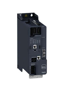
Variable Speed Drive - 0.75kW- 400V - 3 Phases - Altivar ATV340 Ethernet
Variable Speed Drive Altivar ATV320 - 7.5kW - 200V - 3Phase - compact
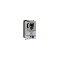
This Altivar 212 variable speed drive can feed 3-phase asynchronous motors. Its protection index is IP21 and it has a built-in EMC filter. It works at a rated power up to 1.5kW / 2hp and a rated voltage from 380V to 480V AC. Its design is based on eco-energy with a reduction in energy consumption of up to 70% compared to a conventional control system. Thanks to its cable temperature rise reduction technology, the Altivar 212 drive offers immediate, disturbance-free operation avoiding additional options such as a line choke or DC choke to deal with current harmonics. It weighs 2kg and its dimensions are, 107mm wide, 143mm high, 150mm deep. It is specifically designed for the most common fluid management applications in tertiary sector buildings (HVAC) like heating, ventilation, air conditioning and pumping. It conforms to international standards IEC/EN 61800-5-1 and IEC/EN 61800-3 (immunity and conducted and radiated EMC emissions). It is also CE, UL, CSA, C-Tick and NOM certified. The Altivar 212 offers optional motor chokes which can increase the maximum cable lengths between the drive and the motor and limit disturbance at the motor terminals. It is designed to be mounted in vertical position (+/- 10 °) on a panel, thanks to 4 fixing holes. It can also be mounted directly on a 35 mm wide DIN rail, thanks to the kit VW3A31852, to order separately. The Altivar 212 drive can easily be adapted to all building management systems thanks to its numerous functions and communication protocols integrated as standard, Modbus, METASYS N2, APOGEE FLN P1 and BACnet.
Main
| Characteristic | Value(s) |
|---|---|
| Device short name | ATV212 |
| Product destination | Asynchronous motors |
| Phase | 3 phase |
| Motor power kW | 1.5 kW |
| Maximum Horse Power Rating | 2 hp |
| Supply voltage limits | 323â¦528 V |
| Supply frequency | 50...60 Hz - 5...5 % |
| Line current | 2.5 A 480 V 3.2 A 380 V |
| Range of Product | Altivar 212 |
| Product or Component Type | Variable speed drive |
| Product Specific Application | Pumps and fans in HVAC |
| Communication Port Protocol | APOGEE FLN BACnet Modbus LonWorks METASYS N2 |
| [Us] rated supply voltage | 380...480 V - 15...10 % |
| EMC filter | Class C2 EMC filter integrated |
| IP degree of protection | IP21 |
Complementary
| Characteristic | Value(s) |
|---|---|
| Apparent power | 2.8 kVA 380 V |
| Continuous output current | 3.7 A 380 V 3.7 A 460 V |
| Maximum transient current | 4 A 60 s |
| Speed drive output frequency | 0.5â¦200 Hz |
| Speed range | 1â¦10 |
| Speed accuracy | +/- 10 % of nominal slip 0.2 Tn to Tn |
| Local signalling | 1 LED (red) for DC bus energized |
| Output voltage | <= power supply voltage |
| Isolation | Electrical between power and control |
| Type of cable | Without mounting kit 1 IEC cable 113 °F (45 °C), copper 90 °C / XLPE/EPR Without mounting kit 1 IEC cable 113 °F (45 °C), copper 70 °C / PVC With UL Type 1 kit 3 UL 508 cable 104 °F (40 °C), copper 75 °C / PVC |
| Electrical connection | VIA, VIB, FM, FLA, FLB, FLC, RY, RC, F, R, RES terminal 0.004 in² (2.5 mm²) / AWG 14 L1/R, L2/S, L3/T terminal 0.009 in² (6 mm²) / AWG 10 |
| Tightening torque | 11.5 lbf.in (1.3 N.m), 11.5 lb.in L1/R, L2/S, L3/T) 5.3 lbf.in (0.6 N.m) VIA, VIB, FM, FLA, FLB, FLC, RY, RC, F, R, RES) |
| Supply | Internal supply for reference potentiometer (1 to 10 kOhm) 10.5 V DC +/- 5 %, <10 A overload and short-circuit protection Internal supply 24 V DC 21â¦27 V), <200 A overload and short-circuit protection |
| Sampling duration | 2 ms +/- 0.5 ms F discrete 2 ms +/- 0.5 ms R discrete 2 ms +/- 0.5 ms RES discrete 3.5 ms +/- 0.5 ms VIA analog 22 ms +/- 0.5 ms VIB analog |
| Response time | FM 2 ms +/- 0.5 ms analog FLA, FLC 7 ms +/- 0.5 ms discrete FLB, FLC 7 ms +/- 0.5 ms discrete RY, RC 7 ms +/- 0.5 ms discrete |
| Accuracy | +/- 0.6 % VIA) for a temperature variation 60 °C +/- 0.6 % VIB) for a temperature variation 60 °C +/- 1 % FM) for a temperature variation 60 °C |
| Linearity error | VIA +/- 0.15 % of maximum value input VIB +/- 0.15 % of maximum value input FM +/- 0.2 % output |
| Analogue output type | FM switch-configurable voltage 0...10 V DC 7620 Ohm 10 bits FM switch-configurable current 0...20 mA 970 Ohm 10 bits |
| Discrete output type | Configurable relay logic FLA, FLC) NO - 100000 cycles Configurable relay logic FLB, FLC) NC - 100000 cycles Configurable relay logic RY, RC) NO - 100000 cycles |
| Minimum switching current | 3 mA 24 V DC configurable relay logic |
| Maximum switching current | 5 A 250 V AC resistive cos phi = 1 L/R = 0 ms FL, R) 5 A 30 V DC resistive cos phi = 1 L/R = 0 ms FL, R) 2 A 250 V AC inductive cos phi = 0.4 L/R = 7 ms FL, R) 2 A 30 V DC inductive cos phi = 0.4 L/R = 7 ms FL, R) |
| Discrete input type | F programmable 24 V DC level 1 PLC 4700 Ohm R programmable 24 V DC level 1 PLC 4700 Ohm RES programmable 24 V DC level 1 PLC 4700 Ohm |
| Discrete input logic | Positive logic (source) F, R, RES), <= 5 V, >= 11 V Negative logic (sink) F, R, RES), >= 16 V, <= 10 V |
| Dielectric strength | 3535 V DC between earth and power terminals 5092 V DC between control and power terminals |
| Insulation resistance | >= 1 mOhm 500 V DC for 1 minute |
| Frequency resolution | Display unit 0.1 Hz Analog input 0.024/50 Hz |
| Communication Service | Read device identification (43) Time out setting from 0.1 to 100 s Monitoring inhibitable Write single register (06) Read holding registers (03) 2 words maximum Write multiple registers (16) 2 words maximum |
| Option card | Communication card LonWorks |
| Power dissipation in W | 78 W |
| air flow | 7132.8 Gal/hr(US) (27 m3/h) |
| Functionality | Mid |
| Specific application | HVAC |
| Variable speed drive application selection | Building - HVAC compressor for scroll Building - HVAC fan Building - HVAC pump |
| Motor power range AC-3 | 1.1â¦2 kW 380â¦440 V 3 phase 1.1â¦2 kW 480â¦500 V 3 phase |
| Motor starter type | Variable speed drive |
| Discrete output number | 2 |
| Analogue input number | 2 |
| Analogue input type | VIA switch-configurable voltage 0...10 V DC 24 V max 30000 Ohm 10 bits VIB configurable voltage 0...10 V DC 24 V max 30000 Ohm 10 bits VIB configurable PTC probe 0...6 probes 1500 Ohm VIA switch-configurable current 0...20 mA 250 Ohm 10 bits |
| Analogue output number | 1 |
| Physical interface | 2-wire RS 485 |
| Connector Type | 1 open style 1 RJ45 |
| Transmission Rate | 9600 bps or 19200 bps |
| Transmission frame | RTU |
| Number of addresses | 1â¦247 |
| Data format | 8 bits, 1 stop, odd even or no configurable parity |
| Type of polarization | No impedance |
| Asynchronous motor control profile | Voltage/frequency ratio - Energy Saving, quadratic U/f Voltage/frequency ratio, 5 points Voltage/frequency ratio, automatic IR compensation (U/f + automatic Uo) Voltage/frequency ratio, 2 points Flux vector control without sensor, standard |
| Torque accuracy | +/- 15 % |
| Transient overtorque | 120 % of nominal motor torque +/- 10 % 60 s |
| Acceleration and deceleration ramps | Linear adjustable separately from 0.01 to 3200 s Automatic based on the load |
| Motor slip compensation | Adjustable Not available in voltage/frequency ratio motor control Automatic whatever the load |
| Switching frequency | 6...16 kHz adjustable 12...16 kHz with derating factor |
| Nominal switching frequency | 12 kHz |
| Braking to standstill | By DC injection |
| Network Frequency | 47.5...63 Hz |
| Prospective line Isc | 5 kA |
| Protection type | Overheating protection drive Thermal power stage drive Short-circuit between motor phases drive Input phase breaks drive Overcurrent between output phases and earth drive Overvoltages on the DC bus drive Break on the control circuit drive Against exceeding limit speed drive Line supply overvoltage and undervoltage drive Line supply undervoltage drive Against input phase loss drive Thermal protection motor Motor phase break motor With PTC probes motor |
| Width | 4.2 in (107 mm) |
| Height | 5.6 in (143 mm) |
| Depth | 5.9 in (150 mm) |
| Product Weight | 4.4 lb(US) (2 kg) |
Variable Speed Drive Altivar 71 - 30kW-40hp - 480V - with EMC filter whitout Graphic Terminal