
 1 year warranty


Ordering
1 piece
85364900
Popular Downloads
Dimensions
45 mm
77 mm
86 mm
0.27 kg
Technical
2
2
0
0
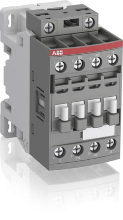
4P
IEC/EN 60947-1, IEC/EN 60947-4-1, UL 60335-2-40 LZGH2 A2L, UL 60947-1, UL 60947-4-1, CSA C22.2 No. 60335-2-40 LZGH2 A2L, CAN/CSA C22.2 No.60947-1, CAN/CSA C22.2 No.60947-4-1
Main Circuit 690 V
Control Circuit 50 / 60 Hz
Main Circuit 50 / 60 Hz
Control Circuit 50 / 60 Hz
Main Circuit 50 / 60 Hz
acc. to IEC 60947-4-1, Open Contactors Θ = 40 °C 35 A
(690 V) 40 °C 30 A
(690 V) 60 °C 30 A
(690 V) 70 °C 26 A
(690 V) 40 °C 30 A
(690 V) 60 °C 30 A
(690 V) 70 °C 26 A
(415 V) 60 °C 18 A
(440 V) 60 °C 18 A
(500 V) 60 °C 15 A
(690 V) 60 °C 10.5 A
(380 / 400 V) 60 °C 18 A
(220 / 230 / 240 V) 60 °C 18 A
(415 V) 60 °C 18 A
(440 V) 60 °C 18 A
(500 V) 60 °C 15 A
(690 V) 60 °C 10.5 A
(380 / 400 V) 60 °C 18 A
(220 / 230 / 240 V) 60 °C 18 A
(400 V) 7.5 kW
(415 V) 9 kW
(440 V) 9 kW
(500 V) 9 kW
(690 V) 9 kW
(380 / 400 V) 7.5 kW
(220 / 230 / 240 V) 4 kW
(400 V) 7.5 kW
(415 V) 9 kW
(440 V) 9 kW
(500 V) 9 kW
(690 V) 9 kW
(380 / 400 V) 7.5 kW
(220 / 230 / 240 V) 4 kW
at 40 °C Ambient Temp, in Free Air, from a Cold State 10 s 150 A
at 40 °C Ambient Temp, in Free Air, from a Cold State 15 min 35 A
at 40 °C Ambient Temp, in Free Air, from a Cold State 1 min 60 A
at 40 °C Ambient Temp, in Free Air, from a Cold State 1 s 300 A
at 40 °C Ambient Temp, in Free Air, from a Cold State 30 s 80 A
cos phi=0.45 (cos phi=0.35 for Ie > 100 A) at 440 V 250 A
cos phi=0.45 (cos phi=0.35 for Ie > 100 A) at 690 V 106 A
cos phi=0.45 (cos phi=0.35 for Ie > 100 A) at 440 V 250 A
cos phi=0.45 (cos phi=0.35 for Ie > 100 A) at 690 V 106 A
acc. to IEC 60947-4-1 690 V
acc. to UL/CSA 600 V
acc. to IEC 60947-4-1 690 V
acc. to UL/CSA 600 V
6 kV
(AC-1) 600 cycles per hour
3600 cycles per hour
50 Hz 48 ... 130 V
60 Hz 48 ... 130 V
DC Operation 48 ... 130 V
50 Hz 48 ... 130 V
60 Hz 48 ... 130 V
DC Operation 48 ... 130 V
at Rated Operating Conditions AC-1 per Pole 1.2 W
at Rated Operating Conditions AC-3 per Pole 0.35 W
at Rated Operating Conditions AC-1 per Pole 1.2 W
at Rated Operating Conditions AC-3 per Pole 0.35 W
Between Coil De-energization and NC Contact Closing 13 ... 98 ms
Between Coil De-energization and NO Contact Opening 11 ... 95 ms
Between Coil Energization and NC Contact Opening 38 ... 90 ms
Between Coil Energization and NO Contact Closing 40 ... 95 ms
Between Coil De-energization and NC Contact Closing 13 ... 98 ms
Between Coil De-energization and NO Contact Opening 11 ... 95 ms
Between Coil Energization and NC Contact Opening 38 ... 90 ms
Between Coil Energization and NO Contact Closing 40 ... 95 ms
TH35-15 (35 x 15 mm Mounting Rail) acc. to IEC 60715
TH35-7.5 (35 x 7.5 mm Mounting Rail) acc. to IEC 60715
TH35-15 (35 x 15 mm Mounting Rail) acc. to IEC 60715
TH35-7.5 (35 x 7.5 mm Mounting Rail) acc. to IEC 60715
2 x M4 Screws Placed Diagonally
Flexible with Ferrule 1/2x 0.75 ... 6 mm²
Flexible with Insulated Ferrule 1x 0.75 ... 4 mm²
Flexible with Insulated Ferrule 2x 0.75 ... 2.5 mm²
Rigid Solid 1/2x 1 ... 4 mm²
Rigid Stranded 1/2x 1 ... 6 mm²
Flexible with Ferrule 1/2x 0.75 ... 6 mm²
Flexible with Insulated Ferrule 1x 0.75 ... 4 mm²
Flexible with Insulated Ferrule 2x 0.75 ... 2.5 mm²
Rigid Solid 1/2x 1 ... 4 mm²
Rigid Stranded 1/2x 1 ... 6 mm²
Rigid Solid 1/2x 1 ... 2.5 mm²
Rigid Stranded 1/2x 1 ... 2.5 mm²
Rigid Solid 1/2x 1 ... 2.5 mm²
Rigid Stranded 1/2x 1 ... 2.5 mm²
Flexible with Ferrule 1/2x 0.75 ... 2.5 mm²
Flexible with Insulated Ferrule 1x 0.75 ... 2.5 mm²
Flexible with Insulated Ferrule 2x 0.75 ... 1.5 mm²
Rigid Solid 1/2x 1 ... 2.5 mm²
Rigid Stranded 1/2x 1 ... 2.5 mm²
Flexible with Ferrule 1/2x 0.75 ... 2.5 mm²
Flexible with Insulated Ferrule 1x 0.75 ... 2.5 mm²
Flexible with Insulated Ferrule 2x 0.75 ... 1.5 mm²
Rigid Solid 1/2x 1 ... 2.5 mm²
Rigid Stranded 1/2x 1 ... 2.5 mm²
Control Circuit 10 mm
Main Circuit 10 mm
Control Circuit 10 mm
Main Circuit 10 mm
acc. to IEC 60529, IEC 60947-1, EN 60529 Coil Terminals IP20
acc. to IEC 60529, IEC 60947-1, EN 60529 Main Terminals IP20
acc. to IEC 60529, IEC 60947-1, EN 60529 Coil Terminals IP20
acc. to IEC 60529, IEC 60947-1, EN 60529 Main Terminals IP20
Control Circuit 1.2 N·m
Main Circuit 1.5 N·m
Control Circuit 1.2 N·m
Main Circuit 1.5 N·m
Screw Terminals
Block Contactor
Technical UL/CSA
Main Circuit 600 V
(600 V AC) 30 A
Rigid Solid 1/2x 16-10 AWG
Rigid Stranded 1/2x 16-10 AWG
Rigid Solid 1/2x 16-10 AWG
Rigid Stranded 1/2x 16-10 AWG
Rigid Solid 1/2x 18-14 AWG
Rigid Stranded 1/2x 18-14 AWG
Rigid Solid 1/2x 18-14 AWG
Rigid Stranded 1/2x 18-14 AWG
Rigid Solid 1/2x 18-14 AWG
Rigid Stranded 1/2x 18-14 AWG
Rigid Solid 1/2x 18-14 AWG
Rigid Stranded 1/2x 18-14 AWG
Control Circuit 11 in·lb
Main Circuit 13 in·lb
Control Circuit 11 in·lb
Main Circuit 13 in·lb
Environmental
Close to Contactor for Storage -60 ... +80 °C
Near Contactor for Operation in Free Air -40 ... 70 °C
Close to Contactor for Storage -60 ... +80 °C
Near Contactor for Operation in Free Air -40 ... 70 °C
Category B according to IEC 60947-1 Annex Q
Without Derating 3000 m
Closed, Shock Direction: B1 25 g
Open, Shock Direction: B1 5 g
Shock Direction: A 30 g
Shock Direction: B2 15 g
Shock Direction: C1 25 g
Shock Direction: C2 25 g
Closed, Shock Direction: B1 25 g
Open, Shock Direction: B1 5 g
Shock Direction: A 30 g
Shock Direction: B2 15 g
Shock Direction: C1 25 g
Shock Direction: C2 25 g
4g Closed Position & 2g Open position 5 ... 300 Hz
3
Material Compliance
Following EU Directive 2011/65/EU and Amendment 2015/863 July 22, 2019
b82ba4d1-f9fa-48c7-9e29-deb0592589c7 China
5dbab33b-aa8a-4202-93c0-ecea6ab15479 Poland
f9070700-d950-4c69-8a0f-ebcdf825fa2f Finland
9db93279-6517-49d7-9c20-b23dc020d873 Czech Republic
b9afb410-c93c-41a7-81da-05f08ac517ac Poland
b2b42fb0-0047-4b6b-9f2e-b3e641fe7401 Norway
76483c7e-a7dc-416f-87cc-53017445d066 Germany
193d2244-8be8-4944-ba0a-bf7c19d2532a Croatia
f18501fc-0e8b-4fbf-bac8-fba0c71fac7b Belgium
35bfce46-0b3e-450a-bb67-c7fc7ab6cc1a Denmark
054982b5-960e-4b27-9536-59326a985d9e Germany
cd04a8f2-94db-4c16-b321-043cfd7d2929 Germany
24fed1f3-5480-441f-8dec-0bc1a3f28e9b Netherlands
e823b907-91e1-436c-b6e1-70961c00a12c Estonia
c2851b3b-7021-423e-b50a-c29531e09ed5 Greece
81dd3642-3446-42b1-8940-cedc023294fb Hungary
b3188f56-0553-4b99-b920-a00f29c1c186 Spain
a978b00a-0a08-4a79-b7e0-13dcf2095a41 France
e047558c-d3d0-4546-b54f-ec1353a9b797 Poland
277a670f-6acf-4aad-a062-60b25ca05c01 Germany
0c67ae62-97b9-42fe-84c1-2ade7545a953 Portugal
f676f883-29a9-4b3b-99a7-2f996eea6ee0 Bulgaria
136940d9-0fc1-4cb2-8b08-03249fd06ea3 Sweden
c7bc6563-0af3-40dd-8ccd-e0f064035883 France
070a43dc-ddf2-4c85-9d9b-45272db23f31 Sweden
a4421e1d-176a-47c0-812a-88ef1a752568 Germany
eb7c59d0-667e-4bae-a532-bff511fe92a8 Hungary
127d8697-c938-442c-9fbb-c0bda0e2d5ab Belgium
5dbab33b-aa8a-4202-93c0-ecea6ab15479 Poland
f9070700-d950-4c69-8a0f-ebcdf825fa2f Finland
9db93279-6517-49d7-9c20-b23dc020d873 Czech Republic
b9afb410-c93c-41a7-81da-05f08ac517ac Poland
b2b42fb0-0047-4b6b-9f2e-b3e641fe7401 Norway
76483c7e-a7dc-416f-87cc-53017445d066 Germany
193d2244-8be8-4944-ba0a-bf7c19d2532a Croatia
f18501fc-0e8b-4fbf-bac8-fba0c71fac7b Belgium
35bfce46-0b3e-450a-bb67-c7fc7ab6cc1a Denmark
054982b5-960e-4b27-9536-59326a985d9e Germany
Business To Business
5. Small Equipment (No External Dimension More Than 50 cm)
ABB EcoSolutions
Recycled Cardboard - 86 %
Recycled Metal - 28 %
Certificates and Declarations
Container Information
box 1 piece
87 mm
79 mm
47 mm
0.27 kg
3471523116320
box 27 piece
250 mm
300 mm
315 mm
14.58 kg
External Classifications and Standards
Q
EC000066 - Power contactor, AC switching
EC000066 - Power contactor, AC switching
EC000066 - Power contactor, AC switching
V11.0 : 27371003
39121529
4758 >> Iec Contactors
3706350
3211401
Ordering
1 piece
85364900
Popular Downloads
Dimensions
45 mm
77 mm
86 mm
0.27 kg
Technical
2
2
0
0
4P
IEC/EN 60947-1, IEC/EN 60947-4-1, UL 60335-2-40 LZGH2 A2L, UL 60947-1, UL 60947-4-1, CSA C22.2 No. 60335-2-40 LZGH2 A2L, CAN/CSA C22.2 No.60947-1, CAN/CSA C22.2 No.60947-4-1
Main Circuit 690 V
Control Circuit 50 / 60 Hz
Main Circuit 50 / 60 Hz
Control Circuit 50 / 60 Hz
Main Circuit 50 / 60 Hz
acc. to IEC 60947-4-1, Open Contactors Θ = 40 °C 35 A
(690 V) 40 °C 30 A
(690 V) 60 °C 30 A
(690 V) 70 °C 26 A
(690 V) 40 °C 30 A
(690 V) 60 °C 30 A
(690 V) 70 °C 26 A
(415 V) 60 °C 18 A
(440 V) 60 °C 18 A
(500 V) 60 °C 15 A
(690 V) 60 °C 10.5 A
(380 / 400 V) 60 °C 18 A
(220 / 230 / 240 V) 60 °C 18 A
(415 V) 60 °C 18 A
(440 V) 60 °C 18 A
(500 V) 60 °C 15 A
(690 V) 60 °C 10.5 A
(380 / 400 V) 60 °C 18 A
(220 / 230 / 240 V) 60 °C 18 A
(400 V) 7.5 kW
(415 V) 9 kW
(440 V) 9 kW
(500 V) 9 kW
(690 V) 9 kW
(380 / 400 V) 7.5 kW
(220 / 230 / 240 V) 4 kW
(400 V) 7.5 kW
(415 V) 9 kW
(440 V) 9 kW
(500 V) 9 kW
(690 V) 9 kW
(380 / 400 V) 7.5 kW
(220 / 230 / 240 V) 4 kW
at 40 °C Ambient Temp, in Free Air, from a Cold State 10 s 150 A
at 40 °C Ambient Temp, in Free Air, from a Cold State 15 min 35 A
at 40 °C Ambient Temp, in Free Air, from a Cold State 1 min 60 A
at 40 °C Ambient Temp, in Free Air, from a Cold State 1 s 300 A
at 40 °C Ambient Temp, in Free Air, from a Cold State 30 s 80 A
at 40 °C Ambient Temp, in Free Air, from a Cold State 10 s 150 A
at 40 °C Ambient Temp, in Free Air, from a Cold State 15 min 35 A
at 40 °C Ambient Temp, in Free Air, from a Cold State 1 min 60 A
at 40 °C Ambient Temp, in Free Air, from a Cold State 1 s 300 A
at 40 °C Ambient Temp, in Free Air, from a Cold State 30 s 80 A
cos phi=0.45 (cos phi=0.35 for Ie > 100 A) at 440 V 250 A
cos phi=0.45 (cos phi=0.35 for Ie > 100 A) at 690 V 106 A
cos phi=0.45 (cos phi=0.35 for Ie > 100 A) at 440 V 250 A
cos phi=0.45 (cos phi=0.35 for Ie > 100 A) at 690 V 106 A
acc. to IEC 60947-4-1 690 V
acc. to UL/CSA 600 V
acc. to IEC 60947-4-1 690 V
acc. to UL/CSA 600 V
6 kV
(AC-1) 600 cycles per hour
3600 cycles per hour
50 Hz 100 ... 250 V
60 Hz 100 ... 250 V
DC Operation 100 ... 250 V
50 Hz 100 ... 250 V
60 Hz 100 ... 250 V
DC Operation 100 ... 250 V
at Rated Operating Conditions AC-1 per Pole 1.2 W
at Rated Operating Conditions AC-3 per Pole 0.35 W
at Rated Operating Conditions AC-1 per Pole 1.2 W
at Rated Operating Conditions AC-3 per Pole 0.35 W
Between Coil De-energization and NC Contact Closing 13 ... 98 ms
Between Coil De-energization and NO Contact Opening 11 ... 95 ms
Between Coil Energization and NC Contact Opening 38 ... 90 ms
Between Coil Energization and NO Contact Closing 40 ... 95 ms
Between Coil De-energization and NC Contact Closing 13 ... 98 ms
Between Coil De-energization and NO Contact Opening 11 ... 95 ms
Between Coil Energization and NC Contact Opening 38 ... 90 ms
Between Coil Energization and NO Contact Closing 40 ... 95 ms
TH35-15 (35 x 15 mm Mounting Rail) acc. to IEC 60715
TH35-7.5 (35 x 7.5 mm Mounting Rail) acc. to IEC 60715
TH35-15 (35 x 15 mm Mounting Rail) acc. to IEC 60715
TH35-7.5 (35 x 7.5 mm Mounting Rail) acc. to IEC 60715
2 x M4 Screws Placed Diagonally
Flexible with Ferrule 1/2x 0.75 ... 6 mm²
Flexible with Insulated Ferrule 1x 0.75 ... 4 mm²
Flexible with Insulated Ferrule 2x 0.75 ... 2.5 mm²
Rigid Solid 1/2x 1 ... 4 mm²
Rigid Stranded 1/2x 1 ... 6 mm²
Flexible with Ferrule 1/2x 0.75 ... 6 mm²
Flexible with Insulated Ferrule 1x 0.75 ... 4 mm²
Flexible with Insulated Ferrule 2x 0.75 ... 2.5 mm²
Rigid Solid 1/2x 1 ... 4 mm²
Rigid Stranded 1/2x 1 ... 6 mm²
Rigid Solid 1/2x 1 ... 2.5 mm²
Rigid Stranded 1/2x 1 ... 2.5 mm²
Rigid Solid 1/2x 1 ... 2.5 mm²
Rigid Stranded 1/2x 1 ... 2.5 mm²
Flexible with Ferrule 1/2x 0.75 ... 2.5 mm²
Flexible with Insulated Ferrule 1x 0.75 ... 2.5 mm²
Flexible with Insulated Ferrule 2x 0.75 ... 1.5 mm²
Rigid Solid 1/2x 1 ... 2.5 mm²
Rigid Stranded 1/2x 1 ... 2.5 mm²
Flexible with Ferrule 1/2x 0.75 ... 2.5 mm²
Flexible with Insulated Ferrule 1x 0.75 ... 2.5 mm²
Flexible with Insulated Ferrule 2x 0.75 ... 1.5 mm²
Rigid Solid 1/2x 1 ... 2.5 mm²
Rigid Stranded 1/2x 1 ... 2.5 mm²
Control Circuit 10 mm
Main Circuit 10 mm
Control Circuit 10 mm
Main Circuit 10 mm
acc. to IEC 60529, IEC 60947-1, EN 60529 Coil Terminals IP20
acc. to IEC 60529, IEC 60947-1, EN 60529 Main Terminals IP20
acc. to IEC 60529, IEC 60947-1, EN 60529 Coil Terminals IP20
acc. to IEC 60529, IEC 60947-1, EN 60529 Main Terminals IP20
Control Circuit 1.2 N·m
Main Circuit 1.5 N·m
Control Circuit 1.2 N·m
Main Circuit 1.5 N·m
Screw Terminals
Block Contactor
Technical UL/CSA
Main Circuit 600 V
(600 V AC) 30 A
Rigid Solid 1/2x 16-10 AWG
Rigid Stranded 1/2x 16-10 AWG
Rigid Solid 1/2x 16-10 AWG
Rigid Stranded 1/2x 16-10 AWG
Rigid Solid 1/2x 18-14 AWG
Rigid Stranded 1/2x 18-14 AWG
Rigid Solid 1/2x 18-14 AWG
Rigid Stranded 1/2x 18-14 AWG
Rigid Solid 1/2x 18-14 AWG
Rigid Stranded 1/2x 18-14 AWG
Rigid Solid 1/2x 18-14 AWG
Rigid Stranded 1/2x 18-14 AWG
Control Circuit 11 in·lb
Main Circuit 13 in·lb
Control Circuit 11 in·lb
Main Circuit 13 in·lb
Environmental
Close to Contactor for Storage -60 ... +80 °C
Near Contactor for Operation in Free Air -40 ... 70 °C
Close to Contactor for Storage -60 ... +80 °C
Near Contactor for Operation in Free Air -40 ... 70 °C
Category B according to IEC 60947-1 Annex Q
Without Derating 3000 m
Closed, Shock Direction: B1 25 g
Open, Shock Direction: B1 5 g
Shock Direction: A 30 g
Shock Direction: B2 15 g
Shock Direction: C1 25 g
Shock Direction: C2 25 g
Closed, Shock Direction: B1 25 g
Open, Shock Direction: B1 5 g
Shock Direction: A 30 g
Shock Direction: B2 15 g
Shock Direction: C1 25 g
Shock Direction: C2 25 g
4g Closed Position & 2g Open position 5 ... 300 Hz
3
Material Compliance
Following EU Directive 2011/65/EU and Amendment 2015/863 July 22, 2019
9d8a072b-a8f5-4676-b483-01d7b0790faf China
b78cfaf1-eadb-4bb4-97dc-2a1cdf017461 Hungary
d03ecc2e-d359-4279-a453-0b53c3f346f3 Estonia
4c4da815-9e57-4338-b4c2-c7dd6d469ae4 Bulgaria
12215a01-d5d4-487d-aefc-49a631950c59 Finland
87c60133-0842-409b-8367-9b128052e0c3 Croatia
f604823e-18bf-4922-8d45-09f7ae770cf3 Czech Republic
5dfe0032-f993-48b1-8ef0-af08f8bea918 Belgium
f9d37d51-2e64-4d5a-a152-fe4919c49331 France
d1b305d9-6f2a-4e41-ade5-46c6357ac787 Sweden
1b6a6cb1-5656-446b-a4c9-f09ef3b838ca Germany
f9fd8f69-6fc5-4874-aba0-ae59a8eecbbb France
50cef61b-b111-48ff-8211-fde63d5ff29e Portugal
54da4f40-0f88-4def-a444-ff7927ba1f07 Germany
f4cc6c46-9b79-4964-a25a-b54e14ade8a6 Denmark
95de85cc-dc9e-4048-8fc5-484fa27e66c1 Sweden
0b1aada1-a86d-4aa8-a299-216c2b16c542 Germany
82206802-2db8-4129-9320-194156a7e7aa Germany
31b71a14-e935-43b5-a7fb-b4025b2bd8f9 Poland
5d487ee1-780e-4c73-9d1e-cd9046b9d83c Greece
0be059b6-8df7-49d2-aa16-b7a2201a1640 Poland
bba2756c-ccd3-4d1d-b838-e797a4a7c48d Germany
4a077ff3-f7a0-413b-918b-e31b6c07b1e0 Poland
4e4b8581-eb7f-41c4-a428-e52606345475 Netherlands
59401d2b-63eb-484c-a62a-1c06a8b5d0ad Norway
ca90f5a0-0ce5-4b0d-9678-e9fb8858a272 Hungary
62e546af-91bc-4db0-a50b-785fd57b2bb6 Belgium
62faea84-9cb9-46e6-be9a-92e0980d1148 Spain
b78cfaf1-eadb-4bb4-97dc-2a1cdf017461 Hungary
d03ecc2e-d359-4279-a453-0b53c3f346f3 Estonia
4c4da815-9e57-4338-b4c2-c7dd6d469ae4 Bulgaria
12215a01-d5d4-487d-aefc-49a631950c59 Finland
87c60133-0842-409b-8367-9b128052e0c3 Croatia
f604823e-18bf-4922-8d45-09f7ae770cf3 Czech Republic
5dfe0032-f993-48b1-8ef0-af08f8bea918 Belgium
f9d37d51-2e64-4d5a-a152-fe4919c49331 France
d1b305d9-6f2a-4e41-ade5-46c6357ac787 Sweden
1b6a6cb1-5656-446b-a4c9-f09ef3b838ca Germany
Business To Business
5. Small Equipment (No External Dimension More Than 50 cm)
ABB EcoSolutions
Recycled Cardboard - 86 %
Recycled Metal - 28 %
Certificates and Declarations
Container Information
box 1 piece
87 mm
79 mm
47 mm
0.27 kg
3471523116337
box 27 piece
250 mm
300 mm
315 mm
14.58 kg
External Classifications and Standards
Q
EC000066 - Power contactor, AC switching
EC000066 - Power contactor, AC switching
EC000066 - Power contactor, AC switching
V11.0 : 27371003
39121529
4758 >> Iec Contactors
3706351
3211402

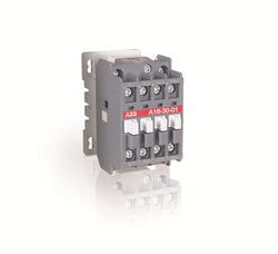
A16-30-01 24V 50Hz / 24V 60Hz Contactor

A16-30-10 380-400V 50Hz / 400-415V 60Hz Contactor
ABB
1SBL181001R8401 ABB - A16-30-01 110V 50Hz / 110-120V 60Hz
Sale price
6,125.00 kr
Only 1 unit leftA16-30-01 110V 50Hz / 110-120V 60Hz Contactor

Ordering
1 piece
85364900
Popular Downloads
Dimensions
45 mm
86 mm
86 mm
0.31 kg
Technical
3
0
0
0
3P
IEC/EN 60947-1, IEC/EN 60947-4-1, UL 60335-2-40 LZGH2 A2L, UL 60947-4-1, CSA C22.2 No. 60335-2-40 LZGH2 A2L, CSA C22.2 No. 60947-4-1
Main Circuit 690 V
Control Circuit 50 / 60 Hz
Main Circuit 50 / 60 Hz
Control Circuit 50 / 60 Hz
Main Circuit 50 / 60 Hz
acc. to IEC 60947-4-1, Open Contactors Θ = 40 °C 50 A
(690 V) 40 °C 50 A
(690 V) 60 °C 42 A
(690 V) 70 °C 37 A
(690 V) 40 °C 50 A
(690 V) 60 °C 42 A
(690 V) 70 °C 37 A
(415 V) 60 °C 32 A
(440 V) 60 °C 32 A
(500 V) 60 °C 28 A
(690 V) 60 °C 21 A
(380 / 400 V) 60 °C 32 A
(220 / 230 / 240 V) 60 °C 33 A
(415 V) 60 °C 32 A
(440 V) 60 °C 32 A
(500 V) 60 °C 28 A
(690 V) 60 °C 21 A
(380 / 400 V) 60 °C 32 A
(220 / 230 / 240 V) 60 °C 33 A
(415 V) 60 °C 32 A
(440 V) 60 °C 32 A
(500 V) 60 °C 28 A
(690 V) 60 °C 21 A
(380 / 400 V) 60 °C 32 A
(220 / 230 / 240 V) 60 °C 33 A
(415 V) 60 °C 32 A
(440 V) 60 °C 32 A
(500 V) 60 °C 28 A
(690 V) 60 °C 21 A
(380 / 400 V) 60 °C 32 A
(220 / 230 / 240 V) 60 °C 33 A
(110 V) 2 Poles in Series, 40 °C 50 A
(110 V) 2 Poles in Series, 60 °C 42 A
(110 V) 2 Poles in Series, 70 °C 37 A
(110 V) 3 Poles in Series, 40 °C 50 A
(110 V) 3 Poles in Series, 60 °C 42 A
(110 V) 3 Poles in Series, 70 °C 37 A
(220 V) 3 Poles in Series, 40 °C 50 A
(220 V) 3 Poles in Series, 60 °C 42 A
(220 V) 3 Poles in Series, 70 °C 37 A
(72 V) 1-Pole, 40 °C 50 A
(72 V) 1-Pole, 60 °C 42 A
(72 V) 1-Pole, 70 °C 37 A
(72 V) 2 Poles in Series, 40 °C 50 A
(72 V) 2 Poles in Series, 60 °C 42 A
(72 V) 2 Poles in Series, 70 °C 37 A
(72 V) 3 Poles in Series, 40 °C 50 A
(72 V) 3 Poles in Series, 60 °C 42 A
(72 V) 3 Poles in Series, 70 °C 37 A
(110 V) 2 Poles in Series, 40 °C 50 A
(110 V) 2 Poles in Series, 60 °C 42 A
(110 V) 2 Poles in Series, 70 °C 37 A
(110 V) 3 Poles in Series, 40 °C 50 A
(110 V) 3 Poles in Series, 60 °C 42 A
(110 V) 3 Poles in Series, 70 °C 37 A
(220 V) 3 Poles in Series, 40 °C 50 A
(220 V) 3 Poles in Series, 60 °C 42 A
(220 V) 3 Poles in Series, 70 °C 37 A
(72 V) 1-Pole, 40 °C 50 A
(72 V) 1-Pole, 60 °C 42 A
(72 V) 1-Pole, 70 °C 37 A
(72 V) 2 Poles in Series, 40 °C 50 A
(72 V) 2 Poles in Series, 60 °C 42 A
(72 V) 2 Poles in Series, 70 °C 37 A
(72 V) 3 Poles in Series, 40 °C 50 A
(72 V) 3 Poles in Series, 60 °C 42 A
(72 V) 3 Poles in Series, 70 °C 37 A
(110 V) 2 Poles in Series, 40 °C 50 A
(110 V) 2 Poles in Series, 60 °C 42 A
(110 V) 2 Poles in Series, 70 °C 37 A
(110 V) 3 Poles in Series, 40 °C 50 A
(110 V) 3 Poles in Series, 60 °C 42 A
(110 V) 3 Poles in Series, 70 °C 37 A
(220 V) 3 Poles in Series, 40 °C 50 A
(220 V) 3 Poles in Series, 60 °C 42 A
(220 V) 3 Poles in Series, 70 °C 37 A
(72 V) 1-Pole, 40 °C 50 A
(110 V) 2 Poles in Series, 40 °C 50 A
(110 V) 2 Poles in Series, 60 °C 42 A
(110 V) 2 Poles in Series, 70 °C 37 A
(110 V) 3 Poles in Series, 40 °C 50 A
(110 V) 3 Poles in Series, 60 °C 42 A
(110 V) 3 Poles in Series, 70 °C 37 A
(220 V) 3 Poles in Series, 40 °C 25 A
(220 V) 3 Poles in Series, 60 °C 25 A
(220 V) 3 Poles in Series, 70 °C 25 A
(72 V) 1-Pole, 40 °C 25 A
(72 V) 1-Pole, 60 °C 25 A
(72 V) 1-Pole, 70 °C 25 A
(72 V) 2 Poles in Series, 40 °C 50 A
(72 V) 2 Poles in Series, 60 °C 42 A
(72 V) 2 Poles in Series, 70 °C 37 A
(72 V) 3 Poles in Series, 40 °C 50 A
(72 V) 3 Poles in Series, 60 °C 42 A
(72 V) 3 Poles in Series, 70 °C 37 A
(110 V) 2 Poles in Series, 40 °C 50 A
(110 V) 2 Poles in Series, 60 °C 42 A
(110 V) 2 Poles in Series, 70 °C 37 A
(110 V) 3 Poles in Series, 40 °C 50 A
(110 V) 3 Poles in Series, 60 °C 42 A
(110 V) 3 Poles in Series, 70 °C 37 A
(220 V) 3 Poles in Series, 40 °C 25 A
(220 V) 3 Poles in Series, 60 °C 25 A
(220 V) 3 Poles in Series, 70 °C 25 A
(72 V) 1-Pole, 40 °C 25 A
(400 V) 15 kW
(415 V) 15 kW
(440 V) 18.5 kW
(500 V) 18.5 kW
(690 V) 18.5 kW
(380 / 400 V) 15 kW
(220 / 230 / 240 V) 9 kW
(400 V) 15 kW
(415 V) 15 kW
(440 V) 18.5 kW
(500 V) 18.5 kW
(690 V) 18.5 kW
(380 / 400 V) 15 kW
(220 / 230 / 240 V) 9 kW
(415 V) 15 kW
(440 V) 18.5 kW
(500 V) 18.5 kW
(690 V) 18.5 kW
(380 / 400 V) 15 kW
(220 / 230 / 240 V) 9 kW
(415 V) 15 kW
(440 V) 18.5 kW
(500 V) 18.5 kW
(690 V) 18.5 kW
(380 / 400 V) 15 kW
(220 / 230 / 240 V) 9 kW
at 40 °C Ambient Temp, in Free Air, from a Cold State 10 s 350 A
at 40 °C Ambient Temp, in Free Air, from a Cold State 15 min 50 A
at 40 °C Ambient Temp, in Free Air, from a Cold State 1 min 150 A
at 40 °C Ambient Temp, in Free Air, from a Cold State 1 s 700 A
at 40 °C Ambient Temp, in Free Air, from a Cold State 30 s 225 A
cos phi=0.45 (cos phi=0.35 for Ie > 100 A) at 440 V 500 A
cos phi=0.45 (cos phi=0.35 for Ie > 100 A) at 690 V 200 A
cos phi=0.45 (cos phi=0.35 for Ie > 100 A) at 440 V 500 A
cos phi=0.45 (cos phi=0.35 for Ie > 100 A) at 690 V 200 A
acc. to IEC 60947-4-1 690 V
acc. to UL/CSA 600 V
acc. to IEC 60947-4-1 690 V
acc. to UL/CSA 600 V
6 kV
(AC-1) 600 cycles per hour
(AC-2 / AC-4) 150 cycles per hour
(AC-3) 1200 cycles per hour
(AC-1) 600 cycles per hour
(AC-2 / AC-4) 150 cycles per hour
(AC-3) 1200 cycles per hour
3600 cycles per hour
50 Hz 48 ... 130 V
60 Hz 48 ... 130 V
DC Operation 48 ... 130 V
50 Hz 48 ... 130 V
60 Hz 48 ... 130 V
DC Operation 48 ... 130 V
at Rated Operating Conditions AC-1 per Pole 2.4 W
at Rated Operating Conditions AC-3 per Pole 0.9 W
at Rated Operating Conditions AC-1 per Pole 2.4 W
at Rated Operating Conditions AC-3 per Pole 0.9 W
Between Coil De-energization and NC Contact Closing 13 ... 98 ms
Between Coil De-energization and NO Contact Opening 11 ... 95 ms
Between Coil Energization and NC Contact Opening 38 ... 90 ms
Between Coil Energization and NO Contact Closing 40 ... 95 ms
Between Coil De-energization and NC Contact Closing 13 ... 98 ms
Between Coil De-energization and NO Contact Opening 11 ... 95 ms
Between Coil Energization and NC Contact Opening 38 ... 90 ms
Between Coil Energization and NO Contact Closing 40 ... 95 ms
TH35-15 (35 x 15 mm Mounting Rail) acc. to IEC 60715
TH35-7.5 (35 x 7.5 mm Mounting Rail) acc. to IEC 60715
TH35-15 (35 x 15 mm Mounting Rail) acc. to IEC 60715
TH35-7.5 (35 x 7.5 mm Mounting Rail) acc. to IEC 60715
2 x M4 Screws Placed Diagonally
Flexible with Ferrule 1/2x 1.5 ... 10 mm²
Flexible with Insulated Ferrule 1x 1.5 ... 10 mm²
Flexible with Insulated Ferrule 2x 1.5 ... 4 mm²
Rigid Solid 1/2x 2.5 ... 4 mm²
Rigid Stranded 1/2x 2.5 ... 10 mm²
Flexible with Ferrule 1/2x 1.5 ... 10 mm²
Flexible with Insulated Ferrule 1x 1.5 ... 10 mm²
Flexible with Insulated Ferrule 2x 1.5 ... 4 mm²
Rigid Solid 1/2x 2.5 ... 4 mm²
Rigid Stranded 1/2x 2.5 ... 10 mm²
Flexible with Ferrule 1/2x 0.75 ... 2.5 mm²
Flexible with Insulated Ferrule 1x 0.75 ... 2.5 mm²
Flexible with Insulated Ferrule 2x 0.75 ... 1.5 mm²
Rigid Solid 1/2x 1 ... 2.5 mm²
Rigid Stranded 1/2x 1 ... 2.5 mm²
Flexible with Ferrule 1/2x 0.75 ... 2.5 mm²
Flexible with Insulated Ferrule 1x 0.75 ... 2.5 mm²
Flexible with Insulated Ferrule 2x 0.75 ... 1.5 mm²
Rigid Solid 1/2x 1 ... 2.5 mm²
Rigid Stranded 1/2x 1 ... 2.5 mm²
Control Circuit 10 mm
Main Circuit 14 mm
Control Circuit 10 mm
Main Circuit 14 mm
acc. to IEC 60529, IEC 60947-1, EN 60529 Coil Terminals IP20
acc. to IEC 60529, IEC 60947-1, EN 60529 Main Terminals IP20
acc. to IEC 60529, IEC 60947-1, EN 60529 Coil Terminals IP20
acc. to IEC 60529, IEC 60947-1, EN 60529 Main Terminals IP20
Control Circuit 1.2 N·m
Main Circuit 2.5 N·m
Control Circuit 1.2 N·m
Main Circuit 2.5 N·m
Screw Terminals
Block Contactor
Technical UL/CSA
Main Circuit 600 V
(600 V AC) 50 A
(120 V AC) Single Phase 2 hp
(200 ... 208 V AC) Three Phase 10 hp
(220 ... 240 V AC) Three Phase 10 hp
(240 V AC) Single Phase 5 hp
(440 ... 480 V AC) Three Phase 20 hp
(550 ... 600 V AC) Three Phase 25 hp
(120 V AC) Single Phase 2 hp
(200 ... 208 V AC) Three Phase 10 hp
(220 ... 240 V AC) Three Phase 10 hp
(240 V AC) Single Phase 5 hp
(440 ... 480 V AC) Three Phase 20 hp
(550 ... 600 V AC) Three Phase 25 hp
Rigid Solid 1/2x 14-10 AWG
Rigid Stranded 1/2x 14-8 AWG
Rigid Solid 1/2x 14-10 AWG
Rigid Stranded 1/2x 14-8 AWG
Rigid Solid 1/2x 18-14 AWG
Rigid Stranded 1/2x 18-14 AWG
Rigid Solid 1/2x 18-14 AWG
Rigid Stranded 1/2x 18-14 AWG
Control Circuit 11 in·lb
Main Circuit 22 in·lb
Control Circuit 11 in·lb
Main Circuit 22 in·lb
(120 V AC) Single Phase 24 A
(200 ... 208 V AC) Three Phase 32.2 A
(220 ... 240 V AC) Three Phase 28 A
(240 V AC) Single Phase 28 A
(440 ... 480 V AC) Three Phase 27 A
(550 ... 600 V AC) Three Phase 27 A
(120 V AC) Single Phase 24 A
(200 ... 208 V AC) Three Phase 32.2 A
(220 ... 240 V AC) Three Phase 28 A
(240 V AC) Single Phase 28 A
(440 ... 480 V AC) Three Phase 27 A
(550 ... 600 V AC) Three Phase 27 A
Environmental
Close to Contactor Fitted with Thermal O/L Relay -25 ... 60 °C
Close to Contactor without Thermal O/L Relay -40 ... 70 °C
Close to Contactor for Storage -60 ... +80 °C
Close to Contactor Fitted with Thermal O/L Relay -25 ... 60 °C
Close to Contactor without Thermal O/L Relay -40 ... 70 °C
Close to Contactor for Storage -60 ... +80 °C
acc. to IEC 60068-2-30 and 60068-2-11 - UTE C 63-100 specification II
Without Derating 3000 m
Closed, Shock Direction: B1 25 g
Open, Shock Direction: B1 5 g
Shock Direction: A 30 g
Shock Direction: B2 15 g
Shock Direction: C1 25 g
Shock Direction: C2 25 g
Closed, Shock Direction: B1 25 g
Open, Shock Direction: B1 5 g
Shock Direction: A 30 g
Shock Direction: B2 15 g
Shock Direction: C1 25 g
Shock Direction: C2 25 g
4g Closed Position & 2g Open position 5 ... 300 Hz
3
Material Compliance
Following EU Directive 2011/65/EU and Amendment 2015/863 July 22, 2019
0be8ad75-8f2f-40f6-ac8e-33c30fb42144 China
28b5333c-0c54-4628-977e-1c5f7e083aae Germany
4fbcd450-1c41-4435-b0dd-0e2542a96466 Denmark
2c996047-66bf-4ee0-b437-7d79ce285ef9 Germany
a7ffc3a4-1bb2-4597-8567-0b1252ee75a3 Croatia
42e43a9a-225a-42e2-9b42-897780295034 Germany
e06505e7-956e-4ed3-99ca-86f4a343c7f7 Sweden
6d0bfb70-ba78-4f16-8571-2fab1d93eeff France
7035d353-8292-460b-8326-b9c4ac58c68e Poland
ac9a96de-82c2-4e91-acfb-2feb3d4f93c3 Bulgaria
1e77a365-e24b-4395-bd88-aeb0bba74f61 Portugal
490150cd-a576-4cdf-b0a0-9411dda2951f Belgium
2af1605f-8381-475f-98cd-ef02b22bae3c Hungary
b9f21536-13b8-4656-a131-a00ef4fed5b7 France
b1847994-ee37-47e7-bd77-dab334fb0932 Sweden
01f61056-7186-4974-8e79-1425f615f82b Germany
39d368c7-9674-46a2-9774-c4eb65899223 Poland
26c93282-54b2-4194-a96d-cf3d395293e7 Netherlands
228d1a2d-4784-4f58-8427-85c053ffca5c Hungary
bdb4b868-673a-454e-8970-d82512af9564 Greece
2160ccf7-129f-4739-97ce-5fa812c8c665 Estonia
d3cdb96a-b1c0-456e-ac8d-bfb5806adcfb Belgium
1f161f82-e314-454e-9456-d7712cc9e5cc Norway
60bf08a6-5d28-40e7-8e61-ac43b8bc41ed Finland
474988ab-f328-41f5-8ae3-83073d03145d Poland
fae03f49-ad37-43d1-af1a-11b2e9d319a3 Czech Republic
555c2a7d-f5a0-493f-aba3-bdf164fb8005 Germany
4b799f5f-aaa1-45e4-aec4-2a518971a8ac Spain
28b5333c-0c54-4628-977e-1c5f7e083aae Germany
4fbcd450-1c41-4435-b0dd-0e2542a96466 Denmark
2c996047-66bf-4ee0-b437-7d79ce285ef9 Germany
a7ffc3a4-1bb2-4597-8567-0b1252ee75a3 Croatia
42e43a9a-225a-42e2-9b42-897780295034 Germany
e06505e7-956e-4ed3-99ca-86f4a343c7f7 Sweden
6d0bfb70-ba78-4f16-8571-2fab1d93eeff France
7035d353-8292-460b-8326-b9c4ac58c68e Poland
ac9a96de-82c2-4e91-acfb-2feb3d4f93c3 Bulgaria
1e77a365-e24b-4395-bd88-aeb0bba74f61 Portugal
Business To Business
5. Small Equipment (No External Dimension More Than 50 cm)
ABB EcoSolutions
Recycled Cardboard - 86 %
Recycled Metal - 28 %
Certificates and Declarations
Container Information
box 1 piece
87 mm
87 mm
47 mm
0.31 kg
3471523111226
box 21 piece
250 mm
300 mm
315 mm
13.95 kg
External Classifications and Standards
Q
EC000066 - Power contactor, AC switching
EC000066 - Power contactor, AC switching
EC000066 - Power contactor, AC switching
V11.0 : 27371003
39121529
4758 >> Iec Contactors
3706284
3211381

Ordering
1 piece
85364900
Popular Downloads
Dimensions
45 mm
86 mm
86 mm
0.35 kg
Technical
3
0
0
0
3P
IEC/EN 60947-1, IEC/EN 60947-4-1, UL 60335-2-40 LZGH2 A2L, UL 60947-4-1, CSA C22.2 No. 60335-2-40 LZGH2 A2L, CSA C22.2 No. 60947-4-1
Main Circuit 690 V
Control Circuit 50 / 60 Hz
Main Circuit 50 / 60 Hz
Control Circuit 50 / 60 Hz
Main Circuit 50 / 60 Hz
acc. to IEC 60947-4-1, Open Contactors Θ = 40 °C 50 A
(690 V) 40 °C 50 A
(690 V) 60 °C 42 A
(690 V) 70 °C 37 A
(690 V) 40 °C 50 A
(690 V) 60 °C 42 A
(690 V) 70 °C 37 A
(415 V) 60 °C 32 A
(440 V) 60 °C 32 A
(500 V) 60 °C 28 A
(690 V) 60 °C 21 A
(380 / 400 V) 60 °C 32 A
(220 / 230 / 240 V) 60 °C 33 A
(415 V) 60 °C 32 A
(440 V) 60 °C 32 A
(500 V) 60 °C 28 A
(690 V) 60 °C 21 A
(380 / 400 V) 60 °C 32 A
(220 / 230 / 240 V) 60 °C 33 A
(415 V) 60 °C 32 A
(440 V) 60 °C 32 A
(500 V) 60 °C 28 A
(690 V) 60 °C 21 A
(380 / 400 V) 60 °C 32 A
(220 / 230 / 240 V) 60 °C 33 A
(415 V) 60 °C 32 A
(440 V) 60 °C 32 A
(500 V) 60 °C 28 A
(690 V) 60 °C 21 A
(380 / 400 V) 60 °C 32 A
(220 / 230 / 240 V) 60 °C 33 A
(110 V) 2 Poles in Series, 40 °C 50 A
(110 V) 2 Poles in Series, 60 °C 42 A
(110 V) 2 Poles in Series, 70 °C 37 A
(110 V) 3 Poles in Series, 40 °C 50 A
(110 V) 3 Poles in Series, 60 °C 42 A
(110 V) 3 Poles in Series, 70 °C 37 A
(220 V) 3 Poles in Series, 40 °C 50 A
(220 V) 3 Poles in Series, 60 °C 42 A
(220 V) 3 Poles in Series, 70 °C 37 A
(72 V) 1-Pole, 40 °C 50 A
(72 V) 1-Pole, 60 °C 42 A
(72 V) 1-Pole, 70 °C 37 A
(72 V) 2 Poles in Series, 40 °C 50 A
(72 V) 2 Poles in Series, 60 °C 42 A
(72 V) 2 Poles in Series, 70 °C 37 A
(72 V) 3 Poles in Series, 40 °C 50 A
(72 V) 3 Poles in Series, 60 °C 42 A
(72 V) 3 Poles in Series, 70 °C 37 A
(110 V) 2 Poles in Series, 40 °C 50 A
(110 V) 2 Poles in Series, 60 °C 42 A
(110 V) 2 Poles in Series, 70 °C 37 A
(110 V) 3 Poles in Series, 40 °C 50 A
(110 V) 3 Poles in Series, 60 °C 42 A
(110 V) 3 Poles in Series, 70 °C 37 A
(220 V) 3 Poles in Series, 40 °C 50 A
(220 V) 3 Poles in Series, 60 °C 42 A
(220 V) 3 Poles in Series, 70 °C 37 A
(72 V) 1-Pole, 40 °C 50 A
(110 V) 2 Poles in Series, 40 °C 50 A
(110 V) 2 Poles in Series, 60 °C 42 A
(110 V) 2 Poles in Series, 70 °C 37 A
(110 V) 3 Poles in Series, 40 °C 50 A
(110 V) 3 Poles in Series, 60 °C 42 A
(110 V) 3 Poles in Series, 70 °C 37 A
(220 V) 3 Poles in Series, 40 °C 50 A
(220 V) 3 Poles in Series, 60 °C 42 A
(220 V) 3 Poles in Series, 70 °C 37 A
(72 V) 1-Pole, 40 °C 50 A
(72 V) 1-Pole, 60 °C 42 A
(72 V) 1-Pole, 70 °C 37 A
(72 V) 2 Poles in Series, 40 °C 50 A
(72 V) 2 Poles in Series, 60 °C 42 A
(72 V) 2 Poles in Series, 70 °C 37 A
(72 V) 3 Poles in Series, 40 °C 50 A
(72 V) 3 Poles in Series, 60 °C 42 A
(72 V) 3 Poles in Series, 70 °C 37 A
(110 V) 2 Poles in Series, 40 °C 50 A
(110 V) 2 Poles in Series, 60 °C 42 A
(110 V) 2 Poles in Series, 70 °C 37 A
(110 V) 3 Poles in Series, 40 °C 50 A
(110 V) 3 Poles in Series, 60 °C 42 A
(110 V) 3 Poles in Series, 70 °C 37 A
(220 V) 3 Poles in Series, 40 °C 50 A
(220 V) 3 Poles in Series, 60 °C 42 A
(220 V) 3 Poles in Series, 70 °C 37 A
(72 V) 1-Pole, 40 °C 50 A
(110 V) 2 Poles in Series, 40 °C 50 A
(110 V) 2 Poles in Series, 60 °C 42 A
(110 V) 2 Poles in Series, 70 °C 37 A
(110 V) 3 Poles in Series, 40 °C 50 A
(110 V) 3 Poles in Series, 60 °C 42 A
(110 V) 3 Poles in Series, 70 °C 37 A
(220 V) 3 Poles in Series, 40 °C 25 A
(220 V) 3 Poles in Series, 60 °C 25 A
(220 V) 3 Poles in Series, 70 °C 25 A
(72 V) 1-Pole, 40 °C 25 A
(72 V) 1-Pole, 60 °C 25 A
(72 V) 1-Pole, 70 °C 25 A
(72 V) 2 Poles in Series, 40 °C 50 A
(72 V) 2 Poles in Series, 60 °C 42 A
(72 V) 2 Poles in Series, 70 °C 37 A
(72 V) 3 Poles in Series, 40 °C 50 A
(72 V) 3 Poles in Series, 60 °C 42 A
(72 V) 3 Poles in Series, 70 °C 37 A
(110 V) 2 Poles in Series, 40 °C 50 A
(110 V) 2 Poles in Series, 60 °C 42 A
(110 V) 2 Poles in Series, 70 °C 37 A
(110 V) 3 Poles in Series, 40 °C 50 A
(110 V) 3 Poles in Series, 60 °C 42 A
(110 V) 3 Poles in Series, 70 °C 37 A
(220 V) 3 Poles in Series, 40 °C 25 A
(220 V) 3 Poles in Series, 60 °C 25 A
(220 V) 3 Poles in Series, 70 °C 25 A
(72 V) 1-Pole, 40 °C 25 A
(400 V) 15 kW
(415 V) 15 kW
(440 V) 18.5 kW
(500 V) 18.5 kW
(690 V) 18.5 kW
(380 / 400 V) 15 kW
(220 / 230 / 240 V) 9 kW
(400 V) 15 kW
(415 V) 15 kW
(440 V) 18.5 kW
(500 V) 18.5 kW
(690 V) 18.5 kW
(380 / 400 V) 15 kW
(220 / 230 / 240 V) 9 kW
(415 V) 15 kW
(440 V) 18.5 kW
(500 V) 18.5 kW
(690 V) 18.5 kW
(380 / 400 V) 15 kW
(220 / 230 / 240 V) 9 kW
(415 V) 15 kW
(440 V) 18.5 kW
(500 V) 18.5 kW
(690 V) 18.5 kW
(380 / 400 V) 15 kW
(220 / 230 / 240 V) 9 kW
at 40 °C Ambient Temp, in Free Air, from a Cold State 10 s 350 A
at 40 °C Ambient Temp, in Free Air, from a Cold State 15 min 50 A
at 40 °C Ambient Temp, in Free Air, from a Cold State 1 min 150 A
at 40 °C Ambient Temp, in Free Air, from a Cold State 1 s 700 A
at 40 °C Ambient Temp, in Free Air, from a Cold State 30 s 225 A
at 40 °C Ambient Temp, in Free Air, from a Cold State 10 s 350 A
at 40 °C Ambient Temp, in Free Air, from a Cold State 15 min 50 A
at 40 °C Ambient Temp, in Free Air, from a Cold State 1 min 150 A
at 40 °C Ambient Temp, in Free Air, from a Cold State 1 s 700 A
at 40 °C Ambient Temp, in Free Air, from a Cold State 30 s 225 A
cos phi=0.45 (cos phi=0.35 for Ie > 100 A) at 440 V 500 A
cos phi=0.45 (cos phi=0.35 for Ie > 100 A) at 690 V 200 A
cos phi=0.45 (cos phi=0.35 for Ie > 100 A) at 440 V 500 A
cos phi=0.45 (cos phi=0.35 for Ie > 100 A) at 690 V 200 A
acc. to IEC 60947-4-1 690 V
acc. to UL/CSA 600 V
acc. to IEC 60947-4-1 690 V
acc. to UL/CSA 600 V
6 kV
(AC-1) 600 cycles per hour
(AC-2 / AC-4) 150 cycles per hour
(AC-3) 1200 cycles per hour
(AC-1) 600 cycles per hour
(AC-2 / AC-4) 150 cycles per hour
(AC-3) 1200 cycles per hour
3600 cycles per hour
50 Hz 250 ... 500 V
60 Hz 250 ... 500 V
DC Operation 250 ... 500 V
50 Hz 250 ... 500 V
60 Hz 250 ... 500 V
DC Operation 250 ... 500 V
at Rated Operating Conditions AC-1 per Pole 2.4 W
at Rated Operating Conditions AC-3 per Pole 0.9 W
at Rated Operating Conditions AC-1 per Pole 2.4 W
at Rated Operating Conditions AC-3 per Pole 0.9 W
Between Coil De-energization and NC Contact Closing 13 ... 98 ms
Between Coil De-energization and NO Contact Opening 11 ... 95 ms
Between Coil Energization and NC Contact Opening 38 ... 90 ms
Between Coil Energization and NO Contact Closing 40 ... 95 ms
Between Coil De-energization and NC Contact Closing 13 ... 98 ms
Between Coil De-energization and NO Contact Opening 11 ... 95 ms
Between Coil Energization and NC Contact Opening 38 ... 90 ms
Between Coil Energization and NO Contact Closing 40 ... 95 ms
TH35-15 (35 x 15 mm Mounting Rail) acc. to IEC 60715
TH35-7.5 (35 x 7.5 mm Mounting Rail) acc. to IEC 60715
TH35-15 (35 x 15 mm Mounting Rail) acc. to IEC 60715
TH35-7.5 (35 x 7.5 mm Mounting Rail) acc. to IEC 60715
2 x M4 Screws Placed Diagonally
Flexible with Ferrule 1/2x 1.5 ... 10 mm²
Flexible with Insulated Ferrule 1x 1.5 ... 10 mm²
Flexible with Insulated Ferrule 2x 1.5 ... 4 mm²
Rigid Solid 1/2x 2.5 ... 4 mm²
Rigid Stranded 1/2x 2.5 ... 10 mm²
Flexible with Ferrule 1/2x 1.5 ... 10 mm²
Flexible with Insulated Ferrule 1x 1.5 ... 10 mm²
Flexible with Insulated Ferrule 2x 1.5 ... 4 mm²
Rigid Solid 1/2x 2.5 ... 4 mm²
Rigid Stranded 1/2x 2.5 ... 10 mm²
Flexible with Ferrule 1/2x 0.75 ... 2.5 mm²
Flexible with Insulated Ferrule 1x 0.75 ... 2.5 mm²
Flexible with Insulated Ferrule 2x 0.75 ... 1.5 mm²
Rigid Solid 1/2x 1 ... 2.5 mm²
Rigid Stranded 1/2x 1 ... 2.5 mm²
Flexible with Ferrule 1/2x 0.75 ... 2.5 mm²
Flexible with Insulated Ferrule 1x 0.75 ... 2.5 mm²
Flexible with Insulated Ferrule 2x 0.75 ... 1.5 mm²
Rigid Solid 1/2x 1 ... 2.5 mm²
Rigid Stranded 1/2x 1 ... 2.5 mm²
Control Circuit 10 mm
Main Circuit 14 mm
Control Circuit 10 mm
Main Circuit 14 mm
acc. to IEC 60529, IEC 60947-1, EN 60529 Coil Terminals IP20
acc. to IEC 60529, IEC 60947-1, EN 60529 Main Terminals IP20
acc. to IEC 60529, IEC 60947-1, EN 60529 Coil Terminals IP20
acc. to IEC 60529, IEC 60947-1, EN 60529 Main Terminals IP20
Control Circuit 1.2 N·m
Main Circuit 2.5 N·m
Control Circuit 1.2 N·m
Main Circuit 2.5 N·m
Screw Terminals
Block Contactor
Technical UL/CSA
Main Circuit 600 V
(600 V AC) 50 A
(120 V AC) Single Phase 2 hp
(200 ... 208 V AC) Three Phase 10 hp
(220 ... 240 V AC) Three Phase 10 hp
(240 V AC) Single Phase 5 hp
(440 ... 480 V AC) Three Phase 20 hp
(550 ... 600 V AC) Three Phase 25 hp
(120 V AC) Single Phase 2 hp
(200 ... 208 V AC) Three Phase 10 hp
(220 ... 240 V AC) Three Phase 10 hp
(240 V AC) Single Phase 5 hp
(440 ... 480 V AC) Three Phase 20 hp
(550 ... 600 V AC) Three Phase 25 hp
Rigid Solid 1/2x 14-10 AWG
Rigid Stranded 1/2x 14-8 AWG
Rigid Solid 1/2x 14-10 AWG
Rigid Stranded 1/2x 14-8 AWG
Rigid Solid 1/2x 18-14 AWG
Rigid Stranded 1/2x 18-14 AWG
Rigid Solid 1/2x 18-14 AWG
Rigid Stranded 1/2x 18-14 AWG
Control Circuit 11 in·lb
Main Circuit 22 in·lb
Control Circuit 11 in·lb
Main Circuit 22 in·lb
(120 V AC) Single Phase 24 A
(200 ... 208 V AC) Three Phase 32.2 A
(220 ... 240 V AC) Three Phase 28 A
(240 V AC) Single Phase 28 A
(440 ... 480 V AC) Three Phase 27 A
(550 ... 600 V AC) Three Phase 27 A
(120 V AC) Single Phase 24 A
(200 ... 208 V AC) Three Phase 32.2 A
(220 ... 240 V AC) Three Phase 28 A
(240 V AC) Single Phase 28 A
(440 ... 480 V AC) Three Phase 27 A
(550 ... 600 V AC) Three Phase 27 A
Environmental
Close to Contactor Fitted with Thermal O/L Relay -25 ... 60 °C
Close to Contactor without Thermal O/L Relay -40 ... 70 °C
Close to Contactor for Storage -60 ... +80 °C
Close to Contactor Fitted with Thermal O/L Relay -25 ... 60 °C
Close to Contactor without Thermal O/L Relay -40 ... 70 °C
Close to Contactor for Storage -60 ... +80 °C
acc. to IEC 60068-2-30 and 60068-2-11 - UTE C 63-100 specification II
Without Derating 3000 m
Closed, Shock Direction: B1 25 g
Open, Shock Direction: B1 5 g
Shock Direction: A 30 g
Shock Direction: B2 15 g
Shock Direction: C1 25 g
Shock Direction: C2 25 g
Closed, Shock Direction: B1 25 g
Open, Shock Direction: B1 5 g
Shock Direction: A 30 g
Shock Direction: B2 15 g
Shock Direction: C1 25 g
Shock Direction: C2 25 g
4g Closed Position & 2g Open position 5 ... 300 Hz
3
Material Compliance
Following EU Directive 2011/65/EU and Amendment 2015/863 July 22, 2019
61477bf2-c463-4050-b5e1-5a540c63b52b China
363a1d88-fcc0-430f-bd86-2f275e16f966 Finland
c218d25d-50e0-4f12-9aed-22dcbb8f45f4 Belgium
22a8e4cc-204c-4043-9e72-c123e0403ceb Norway
d2120623-99b1-46bc-b191-9d8c18136b12 Poland
20a5ee26-1826-4d75-bb1a-8fa47707b245 Spain
65aa5dbf-c83c-4c4c-aff6-ceec3ffb5073 Germany
3f86b7a1-5cb0-4370-a97a-349fe3a2b56f Czech Republic
cd4c4db0-ac1d-4950-bb16-fa4f35fe43ee Croatia
e9a5a48a-18f6-43bf-b1c0-5f280b226405 Denmark
c5df756d-2c6c-4e3d-ba71-b7277fec1319 Germany
32e26db1-13ce-4a9b-93fd-9c36acde46a3 Germany
956e0780-96c7-47b5-a6c9-2bb9337e8a34 Poland
27a1a2a5-abdc-4d80-a424-91134df648ad Hungary
9a689f59-18b2-4cf9-b379-a4ecfc7602e4 Greece
e66d4981-5176-478a-94b3-a6005bb80ff2 Estonia
6b403f91-a07c-4e26-a9e9-3636b56ad8e2 Netherlands
4809203d-4038-4968-87c7-5be669130e13 Germany
31d65ada-d151-4b8a-b8e2-f5ea9ffec81d Portugal
9cff0a2b-7e3c-4f73-bfd1-c4ac01c28f3c Bulgaria
9b31cbad-a0b5-4e2f-ba20-b59010d11b82 Poland
778c32b3-2db6-4472-ac15-d6c5ff87c4bf France
aec0f2d4-7d77-4b17-ba18-935d739b6253 Sweden
3a6aeb5d-e273-45fb-bcb4-be02a262cbd7 Belgium
df83b9e2-8705-49e0-ba6e-b2f81a511b89 France
9b277d18-3a8b-478d-baa6-33f63bb4ea3c Hungary
e0fb86b5-47b3-4459-9cbd-ef66c0fb3bdb Sweden
d01ffed6-0c56-4e7a-852f-02adbdc14898 Germany
363a1d88-fcc0-430f-bd86-2f275e16f966 Finland
c218d25d-50e0-4f12-9aed-22dcbb8f45f4 Belgium
22a8e4cc-204c-4043-9e72-c123e0403ceb Norway
d2120623-99b1-46bc-b191-9d8c18136b12 Poland
20a5ee26-1826-4d75-bb1a-8fa47707b245 Spain
65aa5dbf-c83c-4c4c-aff6-ceec3ffb5073 Germany
3f86b7a1-5cb0-4370-a97a-349fe3a2b56f Czech Republic
cd4c4db0-ac1d-4950-bb16-fa4f35fe43ee Croatia
e9a5a48a-18f6-43bf-b1c0-5f280b226405 Denmark
c5df756d-2c6c-4e3d-ba71-b7277fec1319 Germany
Business To Business
5. Small Equipment (No External Dimension More Than 50 cm)
ABB EcoSolutions
Recycled Cardboard - 86 %
Recycled Metal - 28 %
Certificates and Declarations
Container Information
box 1 piece
87 mm
87 mm
47 mm
0.35 kg
3471523111240
box 21 piece
250 mm
300 mm
315 mm
15.75 kg
External Classifications and Standards
Q
EC000066 - Power contactor, AC switching
EC000066 - Power contactor, AC switching
EC000066 - Power contactor, AC switching
V11.0 : 27371003
39121529
4758 >> Iec Contactors
3706286
3211383

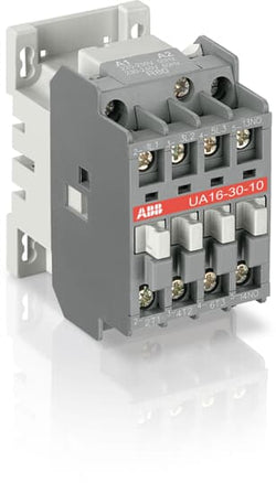
A30-30-10 24V 50Hz / 24V 60Hz Contactor

A16-30-10 400-415V 50Hz / 415-440V 60Hz Contactor

A30-30-10 400-415V 50Hz / 415-440V 60Hz Contactor

TAL30-30-10 77-143V DC Contactor

Ordering
1 piece
85364900
Popular Downloads
Dimensions
44 mm
74 mm
74 mm
0.34 kg
Technical
3
0
1
0
3P
IEC/EN 60947-1, IEC/EN 60947-4-1
Auxiliary Circuit 690 V
Main Circuit 690 V
Auxiliary Circuit 690 V
Main Circuit 690 V
Auxiliary Circuit 50 / 60 Hz
Control Circuit 50 / 60 Hz
Main Circuit 50 / 60 Hz
Auxiliary Circuit 50 / 60 Hz
Control Circuit 50 / 60 Hz
Main Circuit 50 / 60 Hz
acc. to IEC 60947-5-1, Θ = 40 °C 16 A
(500 V) 2 A
(690 V) 2 A
(24 / 127 V) 6 A
(220 / 240 V) 4 A
(380 / 400 V) 3 A
(500 V) 2 A
(690 V) 2 A
(24 / 127 V) 6 A
(220 / 240 V) 4 A
(380 / 400 V) 3 A
(24 V) 6 A / 144 W
(48 V) 2.8 A / 134 W
(72 V) 2 / 144 W
(110 V) 1.1 A / 121 W
(125 V) 1.1 / 138 W
(220 V) 0.55 A / 121 W
(250 V) 0.55 / 138 W
(24 V) 6 A / 144 W
(48 V) 2.8 A / 134 W
(72 V) 2 / 144 W
(110 V) 1.1 A / 121 W
(125 V) 1.1 / 138 W
(220 V) 0.55 A / 121 W
(250 V) 0.55 / 138 W
(230 / 240 V) 40 °C, 50 / 60 Hz 7.5 kvar
(230 / 240 V) 55 °C, 50 / 60 Hz 6.7 kvar
(230 / 240 V) 70 °C, 50 / 60 Hz 6 kvar
(400 / 415 V) 40 °C, 50 / 60 Hz 12.5 kvar
(400 / 415 V) 70 °C, 50 / 60 Hz 10 kvar
(400 / 415 V) 55 °C, 50 / 60 Hz 11.7 kvar
(440 V) 40 °C, 50 / 60 Hz 13.7 kvar
(440 V) 55 °C, 50 / 60 Hz 13 kvar
(440 V) 70 °C, 50 / 60 Hz 11 kvar
(500 / 550 V), 40 °C, 50 / 60 Hz 15.5 kvar
(500 / 550 V) 55 °C, 50 / 60 Hz 14.7 kvar
(500 / 550 V) 70 °C, 50 / 60 Hz 12.5 kvar
(690 V) 40 °C, 50 / 60 Hz 21.5 kvar
(690 V) 55 °C, 50 / 60 Hz 20 kvar
(690 V) 70 °C, 50 / 60 Hz 17 kvar
(230 / 240 V) 40 °C, 50 / 60 Hz 7.5 kvar
(230 / 240 V) 55 °C, 50 / 60 Hz 6.7 kvar
(230 / 240 V) 70 °C, 50 / 60 Hz 6 kvar
(400 / 415 V) 40 °C, 50 / 60 Hz 12.5 kvar
(400 / 415 V) 70 °C, 50 / 60 Hz 10 kvar
(400 / 415 V) 55 °C, 50 / 60 Hz 11.7 kvar
(440 V) 40 °C, 50 / 60 Hz 13.7 kvar
(440 V) 55 °C, 50 / 60 Hz 13 kvar
(440 V) 70 °C, 50 / 60 Hz 11 kvar
(500 / 550 V), 40 °C, 50 / 60 Hz 15.5 kvar
Auxiliary Circuit - gG Type Fuses 10 A
gG Type Fuses 1.5 ... 1.8 A
Auxiliary Circuit - gG Type Fuses 10 A
gG Type Fuses 1.5 ... 1.8 A
for 0.1 s 140 A
for 1 s 100 A
for 0.1 s 140 A
for 1 s 100 A
cos phi=0.45 (cos phi=0.35 for Ie > 100 A) at 440 V 250 A
cos phi=0.45 (cos phi=0.35 for Ie > 100 A) at 690 V 90 A
cos phi=0.45 (cos phi=0.35 for Ie > 100 A) at 440 V 250 A
cos phi=0.45 (cos phi=0.35 for Ie > 100 A) at 690 V 90 A
acc. to IEC 60947-4-1 1000 V
acc. to IEC 60947-5-1 690 V
acc. to UL/CSA 600 V
acc. to IEC 60947-4-1 1000 V
acc. to IEC 60947-5-1 690 V
acc. to UL/CSA 600 V
8 kV
10 million
3600 cycles per hour
17 / 5 VLT4K
50 Hz 220 ... 230 V
60 Hz 230 ... 240 V
50 Hz 220 ... 230 V
60 Hz 230 ... 240 V
Average Holding Value 50 / 60 Hz 8 V·A
Average Pull-in Value 50 Hz 70 V·A
Average Pull-in Value 60 Hz 70 V·A
Pull-in at Max. Rated Control Circuit Voltage 50 Hz 70 V·A
Pull-in at Max. Rated Control Circuit Voltage 60 Hz 80 V·A
Average Holding Value 50 / 60 Hz 8 V·A
Average Pull-in Value 50 Hz 70 V·A
Average Pull-in Value 60 Hz 70 V·A
Pull-in at Max. Rated Control Circuit Voltage 50 Hz 70 V·A
Pull-in at Max. Rated Control Circuit Voltage 60 Hz 80 V·A
at Rated Operating Conditions per Pole 0.1 W
at 6 A per Pole 0.1 W
at Rated Operating Conditions per Pole 0.1 W
at 6 A per Pole 0.1 W
Between Coil De-energization and NO Contact Opening 4 ... 11 ms
Between Coil Energization and NO Contact Closing 10 ... 26 ms
Between Coil De-energization and NO Contact Opening 4 ... 11 ms
Between Coil Energization and NO Contact Closing 10 ... 26 ms
TH35-15 (35 x 15 mm Mounting Rail) acc. to IEC 60715
TH35-7.5 (35 x 7.5 mm Mounting Rail) acc. to IEC 60715
TH35-15 (35 x 15 mm Mounting Rail) acc. to IEC 60715
TH35-7.5 (35 x 7.5 mm Mounting Rail) acc. to IEC 60715
2 x M4 Screws Placed Diagonally
Flexible with Cable End 1/2x 0.75 ... 2.5 mm²
Rigid Solid 1/2x 1 ... 4 mm²
Flexible with Cable End 1/2x 0.75 ... 2.5 mm²
Rigid Solid 1/2x 1 ... 4 mm²
Flexible with Cable End 1/2x 0.75 ... 2.5 mm²
Rigid Solid 1/2x 1 ... 4 mm²
Flexible with Cable End 1/2x 0.75 ... 2.5 mm²
Rigid Solid 1/2x 1 ... 4 mm²
acc. to IEC 60529, IEC 60947-1, EN 60529 Auxiliary Terminals IP20
acc. to IEC 60529, IEC 60947-1, EN 60529 Coil Terminals IP20
acc. to IEC 60529, IEC 60947-1, EN 60529 Main Terminals IP20
acc. to IEC 60529, IEC 60947-1, EN 60529 Auxiliary Terminals IP20
acc. to IEC 60529, IEC 60947-1, EN 60529 Coil Terminals IP20
acc. to IEC 60529, IEC 60947-1, EN 60529 Main Terminals IP20
M 3.5 (+,-) pozidriv 2 screws with cable clamp
Auxiliary Circuit 1 N·m
Control Circuit 1 N·m
Main Circuit 1 N·m
Auxiliary Circuit 1 N·m
Control Circuit 1 N·m
Main Circuit 1 N·m
Screw Terminals
Block Contactor
Technical UL/CSA
1/2x 18-10 AWG
Auxiliary Circuit 9 in·lb
Control Circuit 9 in·lb
Main Circuit 9 in·lb
Auxiliary Circuit 9 in·lb
Control Circuit 9 in·lb
Main Circuit 9 in·lb
Environmental
Close to Contactor for Storage -60 ... +80 °C
Near Contactor for Operation in Free Air (0.85 ... 1.1 Uc) -40 ... +55 °C
Near Contactor for Operation in Free Air (Uc) -40 ... 70 °C
Close to Contactor for Storage -60 ... +80 °C
Near Contactor for Operation in Free Air (0.85 ... 1.1 Uc) -40 ... +55 °C
Near Contactor for Operation in Free Air (Uc) -40 ... 70 °C
acc. to IEC 60068-2-30 and 60068-2-11 - UTE C 63-100 specification II
Without Derating 3000 m
3
Material Compliance
Following EU Directive 2011/65/EU and Amendment 2015/863 July 22, 2019
Business To Business
5. Small Equipment (No External Dimension More Than 50 cm)
Certificates and Declarations
Container Information
box 1 piece
78 mm
76 mm
47 mm
0.34 kg
3471522254801
External Classifications and Standards
Q
EC001079 - Capacitor contactor
EC001079 - Capacitor contactor
EC001079 - Capacitor contactor
V11.0 : 27371006
39121529
Ordering
1 piece
85364900
Popular Downloads
Dimensions
44 mm
74 mm
74 mm
0.34 kg
Technical
3
0
1
0
3P
IEC/EN 60947-1, IEC/EN 60947-4-1
Auxiliary Circuit 690 V
Main Circuit 690 V
Auxiliary Circuit 690 V
Main Circuit 690 V
Auxiliary Circuit 50 / 60 Hz
Control Circuit 50 / 60 Hz
Main Circuit 50 / 60 Hz
Auxiliary Circuit 50 / 60 Hz
Control Circuit 50 / 60 Hz
Main Circuit 50 / 60 Hz
acc. to IEC 60947-5-1, Θ = 40 °C 16 A
(500 V) 2 A
(690 V) 2 A
(24 / 127 V) 6 A
(220 / 240 V) 4 A
(380 / 400 V) 3 A
(500 V) 2 A
(690 V) 2 A
(24 / 127 V) 6 A
(220 / 240 V) 4 A
(380 / 400 V) 3 A
(24 V) 6 A / 144 W
(48 V) 2.8 A / 134 W
(72 V) 2 / 144 W
(110 V) 1.1 A / 121 W
(125 V) 1.1 / 138 W
(220 V) 0.55 A / 121 W
(250 V) 0.55 / 138 W
(24 V) 6 A / 144 W
(48 V) 2.8 A / 134 W
(72 V) 2 / 144 W
(110 V) 1.1 A / 121 W
(125 V) 1.1 / 138 W
(220 V) 0.55 A / 121 W
(250 V) 0.55 / 138 W
(230 / 240 V) 40 °C, 50 / 60 Hz 7.5 kvar
(230 / 240 V) 55 °C, 50 / 60 Hz 6.7 kvar
(230 / 240 V) 70 °C, 50 / 60 Hz 6 kvar
(400 / 415 V) 40 °C, 50 / 60 Hz 12.5 kvar
(400 / 415 V) 70 °C, 50 / 60 Hz 10 kvar
(400 / 415 V) 55 °C, 50 / 60 Hz 11.7 kvar
(440 V) 40 °C, 50 / 60 Hz 13.7 kvar
(440 V) 55 °C, 50 / 60 Hz 13 kvar
(440 V) 70 °C, 50 / 60 Hz 11 kvar
(500 / 550 V), 40 °C, 50 / 60 Hz 15.5 kvar
(500 / 550 V) 55 °C, 50 / 60 Hz 14.7 kvar
(500 / 550 V) 70 °C, 50 / 60 Hz 12.5 kvar
(690 V) 40 °C, 50 / 60 Hz 21.5 kvar
(690 V) 55 °C, 50 / 60 Hz 20 kvar
(690 V) 70 °C, 50 / 60 Hz 17 kvar
(230 / 240 V) 40 °C, 50 / 60 Hz 7.5 kvar
(230 / 240 V) 55 °C, 50 / 60 Hz 6.7 kvar
(230 / 240 V) 70 °C, 50 / 60 Hz 6 kvar
(400 / 415 V) 40 °C, 50 / 60 Hz 12.5 kvar
(400 / 415 V) 70 °C, 50 / 60 Hz 10 kvar
(400 / 415 V) 55 °C, 50 / 60 Hz 11.7 kvar
(440 V) 40 °C, 50 / 60 Hz 13.7 kvar
(440 V) 55 °C, 50 / 60 Hz 13 kvar
(440 V) 70 °C, 50 / 60 Hz 11 kvar
(500 / 550 V), 40 °C, 50 / 60 Hz 15.5 kvar
Auxiliary Circuit - gG Type Fuses 10 A
gG Type Fuses 1.5 ... 1.8 A
Auxiliary Circuit - gG Type Fuses 10 A
gG Type Fuses 1.5 ... 1.8 A
for 0.1 s 140 A
for 1 s 100 A
for 0.1 s 140 A
for 1 s 100 A
cos phi=0.45 (cos phi=0.35 for Ie > 100 A) at 440 V 250 A
cos phi=0.45 (cos phi=0.35 for Ie > 100 A) at 690 V 90 A
cos phi=0.45 (cos phi=0.35 for Ie > 100 A) at 440 V 250 A
cos phi=0.45 (cos phi=0.35 for Ie > 100 A) at 690 V 90 A
acc. to IEC 60947-4-1 1000 V
acc. to IEC 60947-5-1 690 V
acc. to UL/CSA 600 V
acc. to IEC 60947-4-1 1000 V
acc. to IEC 60947-5-1 690 V
acc. to UL/CSA 600 V
8 kV
10 million
3600 cycles per hour
17 / 5 VLT4K
50 Hz 380 ... 400 V
60 Hz 400 ... 415 V
50 Hz 380 ... 400 V
60 Hz 400 ... 415 V
Average Holding Value 50 / 60 Hz 8 V·A
Average Pull-in Value 50 Hz 74 V·A
Average Pull-in Value 60 Hz 70 V·A
Pull-in at Max. Rated Control Circuit Voltage 50 Hz 70 V·A
Pull-in at Max. Rated Control Circuit Voltage 60 Hz 80 V·A
Average Holding Value 50 / 60 Hz 8 V·A
Average Pull-in Value 50 Hz 74 V·A
Average Pull-in Value 60 Hz 70 V·A
Pull-in at Max. Rated Control Circuit Voltage 50 Hz 70 V·A
Pull-in at Max. Rated Control Circuit Voltage 60 Hz 80 V·A
at Rated Operating Conditions per Pole 0.1 W
at 6 A per Pole 0.1 W
at Rated Operating Conditions per Pole 0.1 W
at 6 A per Pole 0.1 W
Between Coil De-energization and NO Contact Opening 4 ... 11 ms
Between Coil Energization and NO Contact Closing 10 ... 26 ms
Between Coil De-energization and NO Contact Opening 4 ... 11 ms
Between Coil Energization and NO Contact Closing 10 ... 26 ms
TH35-15 (35 x 15 mm Mounting Rail) acc. to IEC 60715
TH35-7.5 (35 x 7.5 mm Mounting Rail) acc. to IEC 60715
TH35-15 (35 x 15 mm Mounting Rail) acc. to IEC 60715
TH35-7.5 (35 x 7.5 mm Mounting Rail) acc. to IEC 60715
2 x M4 Screws Placed Diagonally
Flexible with Cable End 1/2x 0.75 ... 2.5 mm²
Rigid Solid 1/2x 1 ... 4 mm²
Flexible with Cable End 1/2x 0.75 ... 2.5 mm²
Rigid Solid 1/2x 1 ... 4 mm²
Flexible with Cable End 1/2x 0.75 ... 2.5 mm²
Rigid Solid 1/2x 1 ... 4 mm²
Flexible with Cable End 1/2x 0.75 ... 2.5 mm²
Rigid Solid 1/2x 1 ... 4 mm²
acc. to IEC 60529, IEC 60947-1, EN 60529 Auxiliary Terminals IP20
acc. to IEC 60529, IEC 60947-1, EN 60529 Coil Terminals IP20
acc. to IEC 60529, IEC 60947-1, EN 60529 Main Terminals IP20
acc. to IEC 60529, IEC 60947-1, EN 60529 Auxiliary Terminals IP20
acc. to IEC 60529, IEC 60947-1, EN 60529 Coil Terminals IP20
acc. to IEC 60529, IEC 60947-1, EN 60529 Main Terminals IP20
M 3.5 (+,-) pozidriv 2 screws with cable clamp
Auxiliary Circuit 1 N·m
Control Circuit 1 N·m
Main Circuit 1 N·m
Auxiliary Circuit 1 N·m
Control Circuit 1 N·m
Main Circuit 1 N·m
Screw Terminals
Block Contactor
Technical UL/CSA
1/2x 18-10 AWG
Auxiliary Circuit 9 in·lb
Control Circuit 9 in·lb
Main Circuit 9 in·lb
Auxiliary Circuit 9 in·lb
Control Circuit 9 in·lb
Main Circuit 9 in·lb
Environmental
Close to Contactor for Storage -60 ... +80 °C
Near Contactor for Operation in Free Air (0.85 ... 1.1 Uc) -40 ... +55 °C
Near Contactor for Operation in Free Air (Uc) -40 ... 70 °C
Close to Contactor for Storage -60 ... +80 °C
Near Contactor for Operation in Free Air (0.85 ... 1.1 Uc) -40 ... +55 °C
Near Contactor for Operation in Free Air (Uc) -40 ... 70 °C
acc. to IEC 60068-2-30 and 60068-2-11 - UTE C 63-100 specification II
Without Derating 3000 m
3
Material Compliance
Following EU Directive 2011/65/EU and Amendment 2015/863 July 22, 2019
Business To Business
5. Small Equipment (No External Dimension More Than 50 cm)
Certificates and Declarations
Container Information
box 1 piece
78 mm
76 mm
47 mm
0.34 kg
3471522254856
External Classifications and Standards
Q
EC001079 - Capacitor contactor
EC001079 - Capacitor contactor
EC001079 - Capacitor contactor
V11.0 : 27371006
39121529

A16-04-00 230-240V 50Hz / 240-260V 60Hz Contactor

Ordering
1 piece
85364900
Popular Downloads
Dimensions
45 mm
101 mm
86 mm
0.4 kg
Technical
4
0
0
0
4P
IEC/EN 60947-1, IEC/EN 60947-4-1, UL 60335-2-40 LZGH2 A2L, UL 60947-1, UL 60947-4-1, CSA C22.2 No. 60335-2-40 LZGH2 A2L, CAN/CSA C22.2 No.60947-1, CAN/CSA C22.2 No.60947-4-1
Main Circuit 690 V
Control Circuit 50 / 60 Hz
Main Circuit 50 / 60 Hz
Control Circuit 50 / 60 Hz
Main Circuit 50 / 60 Hz
acc. to IEC 60947-4-1, Open Contactors Θ = 40 °C 55 A
(690 V) 40 °C 55 A
(690 V) 60 °C 45 A
(690 V) 70 °C 37 A
(690 V) 40 °C 55 A
(690 V) 60 °C 45 A
(690 V) 70 °C 37 A
(415 V) 60 °C 21.2 A
(440 V) 60 °C 20 A
(500 V) 60 °C 17.6 A
(690 V) 60 °C 10.5 A
(380 / 400 V) 60 °C 22 A
(220 / 230 / 240 V) 60 °C 23.2 A
(415 V) 60 °C 21.2 A
(440 V) 60 °C 20 A
(500 V) 60 °C 17.6 A
(690 V) 60 °C 10.5 A
(380 / 400 V) 60 °C 22 A
(220 / 230 / 240 V) 60 °C 23.2 A
(110 V) 2 Poles in Series, 40 °C 55 A
(110 V) 2 Poles in Series, 60 °C 45 A
(110 V) 2 Poles in Series, 70 °C 37 A
(110 V) 3 Poles in Series, 40 °C 55 A
(110 V) 3 Poles in Series, 60 °C 45 A
(110 V) 3 Poles in Series, 70 °C 37 A
(110 V) 4 Poles in Series, 40 °C 55 A
(110 V) 4 Poles in Series, 60 °C 45 A
(110 V) 4 Poles in Series, 70 °C 37 A
(220 V) 3 Poles in Series, 40 °C 55 A
(220 V) 3 Poles in Series, 60 °C 45 A
(220 V) 3 Poles in Series, 70 °C 37 A
(220 V) 4 Poles in Series, 40 °C 55 A
(220 V) 4 Poles in Series, 60 °C 45 A
(220 V) 4 Poles in Series, 70 °C 37 A
(72 V) 1-Pole, 40 °C 55 A
(72 V) 1-Pole, 60 °C 45 A
(72 V) 1-Pole, 70 °C 37 A
(72 V) 2 Poles in Series, 40 °C 55 A
(72 V) 2 Poles in Series, 60 °C 45 A
(72 V) 2 Poles in Series, 70 °C 37 A
(72 V) 3 Poles in Series, 40 °C 55 A
(72 V) 3 Poles in Series, 60 °C 45 A
(72 V) 3 Poles in Series, 70 °C 37 A
(72 V) 4 Poles in Series, 40 °C 55 A
(72 V) 4 Poles in Series, 60 °C 45 A
(72 V) 4 Poles in Series, 70 °C 37 A
(110 V) 2 Poles in Series, 40 °C 55 A
(110 V) 2 Poles in Series, 60 °C 45 A
(110 V) 2 Poles in Series, 70 °C 37 A
(110 V) 3 Poles in Series, 40 °C 55 A
(110 V) 3 Poles in Series, 60 °C 45 A
(110 V) 3 Poles in Series, 70 °C 37 A
(110 V) 4 Poles in Series, 40 °C 55 A
(110 V) 4 Poles in Series, 60 °C 45 A
(110 V) 4 Poles in Series, 70 °C 37 A
(220 V) 3 Poles in Series, 40 °C 55 A
(400 V) 11 kW
(415 V) 11 kW
(440 V) 11 kW
(500 V) 11 kW
(690 V) 9 kW
(220 / 230 / 240 V) 5.5 kW
(400 V) 11 kW
(415 V) 11 kW
(440 V) 11 kW
(500 V) 11 kW
(690 V) 9 kW
(220 / 230 / 240 V) 5.5 kW
at 40 °C Ambient Temp, in Free Air, from a Cold State 10 s 300 A
at 40 °C Ambient Temp, in Free Air, from a Cold State 15 min 55 A
at 40 °C Ambient Temp, in Free Air, from a Cold State 1 min 150 A
at 40 °C Ambient Temp, in Free Air, from a Cold State 1 s 450 A
at 40 °C Ambient Temp, in Free Air, from a Cold State 30 s 225 A
acc. to IEC 60947-4-1 690 V
acc. to UL/CSA 600 V
acc. to IEC 60947-4-1 690 V
acc. to UL/CSA 600 V
6 kV
(AC-1) 600 cycles per hour
3600 cycles per hour
50 Hz 24 ... 60 V
60 Hz 24 ... 60 V
DC Operation 20 ... 60 V
50 Hz 24 ... 60 V
60 Hz 24 ... 60 V
DC Operation 20 ... 60 V
at Rated Operating Conditions AC-1 per Pole 2.3 W
at Rated Operating Conditions AC-3 per Pole 0.42 W
at Rated Operating Conditions AC-1 per Pole 2.3 W
at Rated Operating Conditions AC-3 per Pole 0.42 W
Between Coil De-energization and NC Contact Closing 13 ... 98 ms
Between Coil De-energization and NO Contact Opening 11 ... 95 ms
Between Coil Energization and NC Contact Opening 38 ... 90 ms
Between Coil Energization and NO Contact Closing 40 ... 95 ms
Between Coil De-energization and NC Contact Closing 13 ... 98 ms
Between Coil De-energization and NO Contact Opening 11 ... 95 ms
Between Coil Energization and NC Contact Opening 38 ... 90 ms
Between Coil Energization and NO Contact Closing 40 ... 95 ms
TH35-15 (35 x 15 mm Mounting Rail) acc. to IEC 60715
TH35-7.5 (35 x 7.5 mm Mounting Rail) acc. to IEC 60715
TH35-15 (35 x 15 mm Mounting Rail) acc. to IEC 60715
TH35-7.5 (35 x 7.5 mm Mounting Rail) acc. to IEC 60715
2 x M4 Screws Placed Diagonally
Flexible with Ferrule 1/2x 1.5 ... 16 mm²
Flexible with Insulated Ferrule 1/2x 1.5 ... 16 mm²
Rigid Solid 1/2x 1.5 ... 4 mm²
Rigid Stranded 1/2x 1.5 ... 16 mm²
Flexible with Ferrule 1/2x 1.5 ... 16 mm²
Flexible with Insulated Ferrule 1/2x 1.5 ... 16 mm²
Rigid Solid 1/2x 1.5 ... 4 mm²
Rigid Stranded 1/2x 1.5 ... 16 mm²
Flexible with Ferrule 1/2x 0.75 ... 2.5 mm²
Flexible with Insulated Ferrule 1x 0.75 ... 2.5 mm²
Flexible with Insulated Ferrule 2x 0.75 ... 1.5 mm²
Rigid Solid 1/2x 1 ... 2.5 mm²
Rigid Stranded 1/2x 1 ... 2.5 mm²
Flexible with Ferrule 1/2x 0.75 ... 2.5 mm²
Flexible with Insulated Ferrule 1x 0.75 ... 2.5 mm²
Flexible with Insulated Ferrule 2x 0.75 ... 1.5 mm²
Rigid Solid 1/2x 1 ... 2.5 mm²
Rigid Stranded 1/2x 1 ... 2.5 mm²
Control Circuit 10 mm
Main Circuit 12 mm
Control Circuit 10 mm
Main Circuit 12 mm
acc. to IEC 60529, IEC 60947-1, EN 60529 Coil Terminals IP20
acc. to IEC 60529, IEC 60947-1, EN 60529 Main Terminals IP20
acc. to IEC 60529, IEC 60947-1, EN 60529 Coil Terminals IP20
acc. to IEC 60529, IEC 60947-1, EN 60529 Main Terminals IP20
Control Circuit 1.2 N·m
Main Circuit 2.5 N·m
Control Circuit 1.2 N·m
Main Circuit 2.5 N·m
Screw Terminals
Block Contactor
Technical UL/CSA
Main Circuit 600 V
(600 V AC) 55 A
Rigid Solid 1/2x 16-10 AWG
Rigid Stranded 1/2x 16-6 AWG
Rigid Solid 1/2x 16-10 AWG
Rigid Stranded 1/2x 16-6 AWG
Rigid Solid 1/2x 18-14 AWG
Rigid Stranded 1/2x 18-14 AWG
Rigid Solid 1/2x 18-14 AWG
Rigid Stranded 1/2x 18-14 AWG
Control Circuit 11 in·lb
Main Circuit 22 in·lb
Control Circuit 11 in·lb
Main Circuit 22 in·lb
Environmental
Close to Contactor for Storage -60 ... +80 °C
Near Contactor for Operation in Free Air -40 ... 70 °C
Close to Contactor for Storage -60 ... +80 °C
Near Contactor for Operation in Free Air -40 ... 70 °C
Category B according to IEC 60947-1 Annex Q
Without Derating 3000 m
Closed, Shock Direction: B1 25 g
Open, Shock Direction: B1 5 g
Shock Direction: A 30 g
Shock Direction: B2 15 g
Shock Direction: C1 25 g
Shock Direction: C2 25 g
Closed, Shock Direction: B1 25 g
Open, Shock Direction: B1 5 g
Shock Direction: A 30 g
Shock Direction: B2 15 g
Shock Direction: C1 25 g
Shock Direction: C2 25 g
4g Closed Position & 2g Open position 5 ... 300 Hz
3
Material Compliance
Following EU Directive 2011/65/EU and Amendment 2015/863 July 22, 2019
Business To Business
5. Small Equipment (No External Dimension More Than 50 cm)
ABB EcoSolutions
Recycled Cardboard - 86 %
Recycled Metal - 28 %
Certificates and Declarations
Container Information
box 1 piece
87 mm
103 mm
47 mm
0.4 kg
3471523116115
box 18 piece
250 mm
300 mm
315 mm
14.4 kg
External Classifications and Standards
Q
EC000066 - Power contactor, AC switching
EC000066 - Power contactor, AC switching
EC000066 - Power contactor, AC switching
V11.0 : 27371003
39121529
4758 >> Iec Contactors
3705841
3211528

Ordering
1 piece
85364900
Popular Downloads
Dimensions
44 mm
74 mm
74 mm
0.34 kg
Technical
3
0
1
0
3P
IEC/EN 60947-1, IEC/EN 60947-4-1
Auxiliary Circuit 690 V
Main Circuit 690 V
Auxiliary Circuit 690 V
Main Circuit 690 V
Auxiliary Circuit 50 / 60 Hz
Control Circuit 50 / 60 Hz
Main Circuit 50 / 60 Hz
Auxiliary Circuit 50 / 60 Hz
Control Circuit 50 / 60 Hz
Main Circuit 50 / 60 Hz
acc. to IEC 60947-5-1, Θ = 40 °C 16 A
(500 V) 2 A
(690 V) 2 A
(24 / 127 V) 6 A
(220 / 240 V) 4 A
(380 / 400 V) 3 A
(500 V) 2 A
(690 V) 2 A
(24 / 127 V) 6 A
(220 / 240 V) 4 A
(380 / 400 V) 3 A
(24 V) 6 A / 144 W
(48 V) 2.8 A / 134 W
(72 V) 2 / 144 W
(110 V) 1.1 A / 121 W
(125 V) 1.1 / 138 W
(220 V) 0.55 A / 121 W
(250 V) 0.55 / 138 W
(24 V) 6 A / 144 W
(48 V) 2.8 A / 134 W
(72 V) 2 / 144 W
(110 V) 1.1 A / 121 W
(125 V) 1.1 / 138 W
(220 V) 0.55 A / 121 W
(250 V) 0.55 / 138 W
(230 / 240 V) 40 °C, 50 / 60 Hz 7.5 kvar
(230 / 240 V) 55 °C, 50 / 60 Hz 6.7 kvar
(230 / 240 V) 70 °C, 50 / 60 Hz 6 kvar
(400 / 415 V) 40 °C, 50 / 60 Hz 12.5 kvar
(400 / 415 V) 70 °C, 50 / 60 Hz 10 kvar
(400 / 415 V) 55 °C, 50 / 60 Hz 11.7 kvar
(440 V) 40 °C, 50 / 60 Hz 13.7 kvar
(440 V) 55 °C, 50 / 60 Hz 13 kvar
(440 V) 70 °C, 50 / 60 Hz 11 kvar
(500 / 550 V), 40 °C, 50 / 60 Hz 15.5 kvar
(500 / 550 V) 55 °C, 50 / 60 Hz 14.7 kvar
(500 / 550 V) 70 °C, 50 / 60 Hz 12.5 kvar
(690 V) 40 °C, 50 / 60 Hz 21.5 kvar
(690 V) 55 °C, 50 / 60 Hz 20 kvar
(690 V) 70 °C, 50 / 60 Hz 17 kvar
(230 / 240 V) 40 °C, 50 / 60 Hz 7.5 kvar
(230 / 240 V) 55 °C, 50 / 60 Hz 6.7 kvar
(230 / 240 V) 70 °C, 50 / 60 Hz 6 kvar
(400 / 415 V) 40 °C, 50 / 60 Hz 12.5 kvar
(400 / 415 V) 70 °C, 50 / 60 Hz 10 kvar
(400 / 415 V) 55 °C, 50 / 60 Hz 11.7 kvar
(440 V) 40 °C, 50 / 60 Hz 13.7 kvar
(440 V) 55 °C, 50 / 60 Hz 13 kvar
(440 V) 70 °C, 50 / 60 Hz 11 kvar
(500 / 550 V), 40 °C, 50 / 60 Hz 15.5 kvar
Auxiliary Circuit - gG Type Fuses 10 A
gG Type Fuses 1.5 ... 1.8 A
Auxiliary Circuit - gG Type Fuses 10 A
gG Type Fuses 1.5 ... 1.8 A
for 0.1 s 140 A
for 1 s 100 A
for 0.1 s 140 A
for 1 s 100 A
cos phi=0.45 (cos phi=0.35 for Ie > 100 A) at 440 V 250 A
cos phi=0.45 (cos phi=0.35 for Ie > 100 A) at 690 V 90 A
cos phi=0.45 (cos phi=0.35 for Ie > 100 A) at 440 V 250 A
cos phi=0.45 (cos phi=0.35 for Ie > 100 A) at 690 V 90 A
acc. to IEC 60947-4-1 1000 V
acc. to IEC 60947-5-1 690 V
acc. to UL/CSA 600 V
acc. to IEC 60947-4-1 1000 V
acc. to IEC 60947-5-1 690 V
acc. to UL/CSA 600 V
8 kV
3600 cycles per hour
17 / 5 VLT4K
50 Hz 230 ... 240 V
60 Hz 240 ... 260 V
50 Hz 230 ... 240 V
60 Hz 240 ... 260 V
Average Holding Value 50 / 60 Hz 8 V·A
Average Pull-in Value 50 Hz 74 V·A
Average Pull-in Value 60 Hz 70 V·A
Pull-in at Max. Rated Control Circuit Voltage 50 Hz 70 V·A
Pull-in at Max. Rated Control Circuit Voltage 60 Hz 80 V·A
Average Holding Value 50 / 60 Hz 8 V·A
Average Pull-in Value 50 Hz 74 V·A
Average Pull-in Value 60 Hz 70 V·A
Pull-in at Max. Rated Control Circuit Voltage 50 Hz 70 V·A
Pull-in at Max. Rated Control Circuit Voltage 60 Hz 80 V·A
at Rated Operating Conditions per Pole 0.1 W
at 6 A per Pole 0.1 W
at Rated Operating Conditions per Pole 0.1 W
at 6 A per Pole 0.1 W
Between Coil De-energization and NO Contact Opening 4 ... 11 ms
Between Coil Energization and NO Contact Closing 10 ... 26 ms
Between Coil De-energization and NO Contact Opening 4 ... 11 ms
Between Coil Energization and NO Contact Closing 10 ... 26 ms
TH35-15 (35 x 15 mm Mounting Rail) acc. to IEC 60715
TH35-7.5 (35 x 7.5 mm Mounting Rail) acc. to IEC 60715
TH35-15 (35 x 15 mm Mounting Rail) acc. to IEC 60715
TH35-7.5 (35 x 7.5 mm Mounting Rail) acc. to IEC 60715
2 x M4 Screws Placed Diagonally
Flexible with Cable End 1/2x 0.75 ... 2.5 mm²
Rigid Solid 1/2x 1 ... 4 mm²
Flexible with Cable End 1/2x 0.75 ... 2.5 mm²
Rigid Solid 1/2x 1 ... 4 mm²
Flexible with Cable End 1/2x 0.75 ... 2.5 mm²
Rigid Solid 1/2x 1 ... 4 mm²
Flexible with Cable End 1/2x 0.75 ... 2.5 mm²
Rigid Solid 1/2x 1 ... 4 mm²
acc. to IEC 60529, IEC 60947-1, EN 60529 Auxiliary Terminals IP20
acc. to IEC 60529, IEC 60947-1, EN 60529 Coil Terminals IP20
acc. to IEC 60529, IEC 60947-1, EN 60529 Main Terminals IP20
acc. to IEC 60529, IEC 60947-1, EN 60529 Auxiliary Terminals IP20
acc. to IEC 60529, IEC 60947-1, EN 60529 Coil Terminals IP20
acc. to IEC 60529, IEC 60947-1, EN 60529 Main Terminals IP20
M 3.5 (+,-) pozidriv 2 screws with cable clamp
Auxiliary Circuit 1 N·m
Control Circuit 1 N·m
Main Circuit 1 N·m
Auxiliary Circuit 1 N·m
Control Circuit 1 N·m
Main Circuit 1 N·m
Screw Terminals
Block Contactor
Technical UL/CSA
1/2x 18-10 AWG
Auxiliary Circuit 9 in·lb
Control Circuit 9 in·lb
Main Circuit 9 in·lb
Auxiliary Circuit 9 in·lb
Control Circuit 9 in·lb
Main Circuit 9 in·lb
Environmental
Close to Contactor for Storage -60 ... +80 °C
Near Contactor for Operation in Free Air (0.85 ... 1.1 Uc) -40 ... +55 °C
Near Contactor for Operation in Free Air (Uc) -40 ... 70 °C
Close to Contactor for Storage -60 ... +80 °C
Near Contactor for Operation in Free Air (0.85 ... 1.1 Uc) -40 ... +55 °C
Near Contactor for Operation in Free Air (Uc) -40 ... 70 °C
acc. to IEC 60068-2-30 and 60068-2-11 - UTE C 63-100 specification II
Without Derating 3000 m
3
Material Compliance
Following EU Directive 2011/65/EU and Amendment 2015/863 July 22, 2019
Business To Business
5. Small Equipment (No External Dimension More Than 50 cm)
Certificates and Declarations
Container Information
box 1 piece
78 mm
76 mm
47 mm
0.34 kg
3471522254887
External Classifications and Standards
Q
EC001079 - Capacitor contactor
EC001079 - Capacitor contactor
EC001079 - Capacitor contactor
V11.0 : 27371006
39121529

Ordering
1 piece
85364900
Popular Downloads
Dimensions
45 mm
86 mm
86 mm
0.35 kg
Technical
3
0
0
0
3P
IEC/EN 60947-1, IEC/EN 60947-4-1, UL 60335-2-40 LZGH2 A2L, UL 60947-4-1, CSA C22.2 No. 60335-2-40 LZGH2 A2L, CSA C22.2 No. 60947-4-1
Main Circuit 690 V
Control Circuit 50 / 60 Hz
Main Circuit 50 / 60 Hz
Control Circuit 50 / 60 Hz
Main Circuit 50 / 60 Hz
acc. to IEC 60947-4-1, Open Contactors Θ = 40 °C 50 A
(690 V) 40 °C 50 A
(690 V) 60 °C 42 A
(690 V) 70 °C 37 A
(690 V) 40 °C 50 A
(690 V) 60 °C 42 A
(690 V) 70 °C 37 A
(415 V) 60 °C 38 A
(440 V) 60 °C 38 A
(500 V) 60 °C 33 A
(690 V) 60 °C 24 A
(380 / 400 V) 60 °C 38 A
(220 / 230 / 240 V) 60 °C 40 A
(415 V) 60 °C 38 A
(440 V) 60 °C 38 A
(500 V) 60 °C 33 A
(690 V) 60 °C 24 A
(380 / 400 V) 60 °C 38 A
(220 / 230 / 240 V) 60 °C 40 A
(415 V) 60 °C 38 A
(440 V) 60 °C 38 A
(500 V) 60 °C 33 A
(690 V) 60 °C 24 A
(380 / 400 V) 60 °C 38 A
(220 / 230 / 240 V) 60 °C 40 A
(415 V) 60 °C 38 A
(440 V) 60 °C 38 A
(500 V) 60 °C 33 A
(690 V) 60 °C 24 A
(380 / 400 V) 60 °C 38 A
(220 / 230 / 240 V) 60 °C 40 A
(110 V) 2 Poles in Series, 40 °C 50 A
(110 V) 2 Poles in Series, 60 °C 42 A
(110 V) 2 Poles in Series, 70 °C 37 A
(110 V) 3 Poles in Series, 40 °C 50 A
(110 V) 3 Poles in Series, 60 °C 42 A
(110 V) 3 Poles in Series, 70 °C 37 A
(220 V) 3 Poles in Series, 40 °C 50 A
(220 V) 3 Poles in Series, 60 °C 42 A
(220 V) 3 Poles in Series, 70 °C 37 A
(72 V) 1-Pole, 40 °C 50 A
(72 V) 1-Pole, 60 °C 42 A
(72 V) 1-Pole, 70 °C 37 A
(72 V) 2 Poles in Series, 40 °C 50 A
(72 V) 2 Poles in Series, 60 °C 42 A
(72 V) 2 Poles in Series, 70 °C 37 A
(72 V) 3 Poles in Series, 40 °C 50 A
(72 V) 3 Poles in Series, 60 °C 42 A
(72 V) 3 Poles in Series, 70 °C 37 A
(110 V) 2 Poles in Series, 40 °C 50 A
(110 V) 2 Poles in Series, 60 °C 42 A
(110 V) 2 Poles in Series, 70 °C 37 A
(110 V) 3 Poles in Series, 40 °C 50 A
(110 V) 3 Poles in Series, 60 °C 42 A
(110 V) 3 Poles in Series, 70 °C 37 A
(220 V) 3 Poles in Series, 40 °C 50 A
(220 V) 3 Poles in Series, 60 °C 42 A
(220 V) 3 Poles in Series, 70 °C 37 A
(72 V) 1-Pole, 40 °C 50 A
(110 V) 2 Poles in Series, 40 °C 50 A
(110 V) 2 Poles in Series, 60 °C 42 A
(110 V) 2 Poles in Series, 70 °C 37 A
(110 V) 3 Poles in Series, 40 °C 50 A
(110 V) 3 Poles in Series, 60 °C 42 A
(110 V) 3 Poles in Series, 70 °C 37 A
(220 V) 3 Poles in Series, 40 °C 50 A
(220 V) 3 Poles in Series, 60 °C 42 A
(220 V) 3 Poles in Series, 70 °C 37 A
(72 V) 1-Pole, 40 °C 50 A
(72 V) 1-Pole, 60 °C 42 A
(72 V) 1-Pole, 70 °C 37 A
(72 V) 2 Poles in Series, 40 °C 50 A
(72 V) 2 Poles in Series, 60 °C 42 A
(72 V) 2 Poles in Series, 70 °C 37 A
(72 V) 3 Poles in Series, 40 °C 50 A
(72 V) 3 Poles in Series, 60 °C 42 A
(72 V) 3 Poles in Series, 70 °C 37 A
(110 V) 2 Poles in Series, 40 °C 50 A
(110 V) 2 Poles in Series, 60 °C 42 A
(110 V) 2 Poles in Series, 70 °C 37 A
(110 V) 3 Poles in Series, 40 °C 50 A
(110 V) 3 Poles in Series, 60 °C 42 A
(110 V) 3 Poles in Series, 70 °C 37 A
(220 V) 3 Poles in Series, 40 °C 50 A
(220 V) 3 Poles in Series, 60 °C 42 A
(220 V) 3 Poles in Series, 70 °C 37 A
(72 V) 1-Pole, 40 °C 50 A
(110 V) 2 Poles in Series, 40 °C 50 A
(110 V) 2 Poles in Series, 60 °C 42 A
(110 V) 2 Poles in Series, 70 °C 37 A
(110 V) 3 Poles in Series, 40 °C 50 A
(110 V) 3 Poles in Series, 60 °C 42 A
(110 V) 3 Poles in Series, 70 °C 37 A
(220 V) 3 Poles in Series, 40 °C 25 A
(220 V) 3 Poles in Series, 60 °C 25 A
(220 V) 3 Poles in Series, 70 °C 25 A
(72 V) 1-Pole, 40 °C 25 A
(72 V) 1-Pole, 60 °C 25 A
(72 V) 1-Pole, 70 °C 25 A
(72 V) 2 Poles in Series, 40 °C 50 A
(72 V) 2 Poles in Series, 60 °C 42 A
(72 V) 2 Poles in Series, 70 °C 37 A
(72 V) 3 Poles in Series, 40 °C 50 A
(72 V) 3 Poles in Series, 60 °C 42 A
(72 V) 3 Poles in Series, 70 °C 37 A
(110 V) 2 Poles in Series, 40 °C 50 A
(110 V) 2 Poles in Series, 60 °C 42 A
(110 V) 2 Poles in Series, 70 °C 37 A
(110 V) 3 Poles in Series, 40 °C 50 A
(110 V) 3 Poles in Series, 60 °C 42 A
(110 V) 3 Poles in Series, 70 °C 37 A
(220 V) 3 Poles in Series, 40 °C 25 A
(220 V) 3 Poles in Series, 60 °C 25 A
(220 V) 3 Poles in Series, 70 °C 25 A
(72 V) 1-Pole, 40 °C 25 A
(400 V) 18.5 kW
(415 V) 18.5 kW
(440 V) 22 kW
(500 V) 22 kW
(690 V) 22 kW
(380 / 400 V) 18.5 kW
(220 / 230 / 240 V) 11 kW
(400 V) 18.5 kW
(415 V) 18.5 kW
(440 V) 22 kW
(500 V) 22 kW
(690 V) 22 kW
(380 / 400 V) 18.5 kW
(220 / 230 / 240 V) 11 kW
(415 V) 18.5 kW
(440 V) 22 kW
(500 V) 22 kW
(690 V) 22 kW
(380 / 400 V) 18.5 kW
(220 / 230 / 240 V) 11 kW
(415 V) 18.5 kW
(440 V) 22 kW
(500 V) 22 kW
(690 V) 22 kW
(380 / 400 V) 18.5 kW
(220 / 230 / 240 V) 11 kW
at 40 °C Ambient Temp, in Free Air, from a Cold State 10 s 350 A
at 40 °C Ambient Temp, in Free Air, from a Cold State 15 min 50 A
at 40 °C Ambient Temp, in Free Air, from a Cold State 1 min 150 A
at 40 °C Ambient Temp, in Free Air, from a Cold State 1 s 700 A
at 40 °C Ambient Temp, in Free Air, from a Cold State 30 s 225 A
cos phi=0.45 (cos phi=0.35 for Ie > 100 A) at 440 V 500 A
cos phi=0.45 (cos phi=0.35 for Ie > 100 A) at 690 V 200 A
cos phi=0.45 (cos phi=0.35 for Ie > 100 A) at 440 V 500 A
cos phi=0.45 (cos phi=0.35 for Ie > 100 A) at 690 V 200 A
acc. to IEC 60947-4-1 690 V
acc. to UL/CSA 600 V
acc. to IEC 60947-4-1 690 V
acc. to UL/CSA 600 V
6 kV
(AC-1) 600 cycles per hour
(AC-2 / AC-4) 150 cycles per hour
(AC-3) 1200 cycles per hour
(AC-1) 600 cycles per hour
(AC-2 / AC-4) 150 cycles per hour
(AC-3) 1200 cycles per hour
3600 cycles per hour
50 Hz 24 ... 60 V
60 Hz 24 ... 60 V
DC Operation 20 ... 60 V
50 Hz 24 ... 60 V
60 Hz 24 ... 60 V
DC Operation 20 ... 60 V
at Rated Operating Conditions AC-1 per Pole 2.4 W
at Rated Operating Conditions AC-3 per Pole 1.3 W
at Rated Operating Conditions AC-1 per Pole 2.4 W
at Rated Operating Conditions AC-3 per Pole 1.3 W
Between Coil De-energization and NC Contact Closing 13 ... 98 ms
Between Coil De-energization and NO Contact Opening 11 ... 95 ms
Between Coil Energization and NC Contact Opening 38 ... 90 ms
Between Coil Energization and NO Contact Closing 40 ... 95 ms
Between Coil De-energization and NC Contact Closing 13 ... 98 ms
Between Coil De-energization and NO Contact Opening 11 ... 95 ms
Between Coil Energization and NC Contact Opening 38 ... 90 ms
Between Coil Energization and NO Contact Closing 40 ... 95 ms
TH35-15 (35 x 15 mm Mounting Rail) acc. to IEC 60715
TH35-7.5 (35 x 7.5 mm Mounting Rail) acc. to IEC 60715
TH35-15 (35 x 15 mm Mounting Rail) acc. to IEC 60715
TH35-7.5 (35 x 7.5 mm Mounting Rail) acc. to IEC 60715
2 x M4 Screws Placed Diagonally
Flexible with Ferrule 1/2x 1.5 ... 10 mm²
Flexible with Insulated Ferrule 1x 1.5 ... 10 mm²
Flexible with Insulated Ferrule 2x 1.5 ... 4 mm²
Rigid Solid 1/2x 2.5 ... 4 mm²
Rigid Stranded 1/2x 2.5 ... 10 mm²
Flexible with Ferrule 1/2x 1.5 ... 10 mm²
Flexible with Insulated Ferrule 1x 1.5 ... 10 mm²
Flexible with Insulated Ferrule 2x 1.5 ... 4 mm²
Rigid Solid 1/2x 2.5 ... 4 mm²
Rigid Stranded 1/2x 2.5 ... 10 mm²
Flexible with Ferrule 1/2x 0.75 ... 2.5 mm²
Flexible with Insulated Ferrule 1x 0.75 ... 2.5 mm²
Flexible with Insulated Ferrule 2x 0.75 ... 1.5 mm²
Rigid Solid 1/2x 1 ... 2.5 mm²
Rigid Stranded 1/2x 1 ... 2.5 mm²
Flexible with Ferrule 1/2x 0.75 ... 2.5 mm²
Flexible with Insulated Ferrule 1x 0.75 ... 2.5 mm²
Flexible with Insulated Ferrule 2x 0.75 ... 1.5 mm²
Rigid Solid 1/2x 1 ... 2.5 mm²
Rigid Stranded 1/2x 1 ... 2.5 mm²
Control Circuit 10 mm
Main Circuit 14 mm
Control Circuit 10 mm
Main Circuit 14 mm
acc. to IEC 60529, IEC 60947-1, EN 60529 Coil Terminals IP20
acc. to IEC 60529, IEC 60947-1, EN 60529 Main Terminals IP20
acc. to IEC 60529, IEC 60947-1, EN 60529 Coil Terminals IP20
acc. to IEC 60529, IEC 60947-1, EN 60529 Main Terminals IP20
Control Circuit 1.2 N·m
Main Circuit 2.5 N·m
Control Circuit 1.2 N·m
Main Circuit 2.5 N·m
Screw Terminals
Block Contactor
Technical UL/CSA
Main Circuit 600 V
(600 V AC) 50 A
(120 V AC) Single Phase 2 hp
(200 ... 208 V AC) Three Phase 10 hp
(220 ... 240 V AC) Three Phase 10 hp
(240 V AC) Single Phase 5 hp
(440 ... 480 V AC) Three Phase 25 hp
(550 ... 600 V AC) Three Phase 30 hp
(120 V AC) Single Phase 2 hp
(200 ... 208 V AC) Three Phase 10 hp
(220 ... 240 V AC) Three Phase 10 hp
(240 V AC) Single Phase 5 hp
(440 ... 480 V AC) Three Phase 25 hp
(550 ... 600 V AC) Three Phase 30 hp
Rigid Solid 1/2x 14-10 AWG
Rigid Stranded 1/2x 14-8 AWG
Rigid Solid 1/2x 14-10 AWG
Rigid Stranded 1/2x 14-8 AWG
Rigid Solid 1/2x 18-14 AWG
Rigid Stranded 1/2x 18-14 AWG
Rigid Solid 1/2x 18-14 AWG
Rigid Stranded 1/2x 18-14 AWG
Control Circuit 11 in·lb
Main Circuit 22 in·lb
Control Circuit 11 in·lb
Main Circuit 22 in·lb
(120 V AC) Single Phase 24 A
(200 ... 208 V AC) Three Phase 32.2 A
(220 ... 240 V AC) Three Phase 28 A
(240 V AC) Single Phase 28 A
(440 ... 480 V AC) Three Phase 34 A
(550 ... 600 V AC) Three Phase 32 A
(120 V AC) Single Phase 24 A
(200 ... 208 V AC) Three Phase 32.2 A
(220 ... 240 V AC) Three Phase 28 A
(240 V AC) Single Phase 28 A
(440 ... 480 V AC) Three Phase 34 A
(550 ... 600 V AC) Three Phase 32 A
Environmental
Close to Contactor Fitted with Thermal O/L Relay -25 ... 60 °C
Close to Contactor without Thermal O/L Relay -40 ... 70 °C
Close to Contactor for Storage -60 ... +80 °C
Close to Contactor Fitted with Thermal O/L Relay -25 ... 60 °C
Close to Contactor without Thermal O/L Relay -40 ... 70 °C
Close to Contactor for Storage -60 ... +80 °C
Category B according to IEC 60947-1 Annex Q
Without Derating 3000 m
Closed, Shock Direction: B1 25 g
Open, Shock Direction: B1 5 g
Shock Direction: A 30 g
Shock Direction: B2 15 g
Shock Direction: C1 25 g
Shock Direction: C2 25 g
Closed, Shock Direction: B1 25 g
Open, Shock Direction: B1 5 g
Shock Direction: A 30 g
Shock Direction: B2 15 g
Shock Direction: C1 25 g
Shock Direction: C2 25 g
4g Closed Position & 2g Open position 5 ... 300 Hz
3
Material Compliance
Following EU Directive 2011/65/EU and Amendment 2015/863 July 22, 2019
ec82c775-12da-4dd3-a906-461ad6aecfe2 China
Business To Business
5. Small Equipment (No External Dimension More Than 50 cm)
ABB EcoSolutions
Recycled Cardboard - 86 %
Recycled Metal - 28 %
Certificates and Declarations
Container Information
box 1 piece
87 mm
87 mm
47 mm
0.35 kg
3471523114715
box 21 piece
250 mm
300 mm
315 mm
15.75 kg
External Classifications and Standards
Q
EC000066 - Power contactor, AC switching
EC000066 - Power contactor, AC switching
EC000066 - Power contactor, AC switching
V11.0 : 27371003
39121529
4758 >> Iec Contactors
3706318
3211384
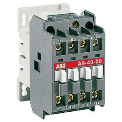
A16-40-00 380-400V 50Hz / 400-415V 60Hz Contactor

Ordering
1 piece
85364900
Popular Downloads
Dimensions
45 mm
101 mm
86 mm
0.4 kg
Technical
4
0
0
0
4P
IEC/EN 60947-1, IEC/EN 60947-4-1, UL 60335-2-40 LZGH2 A2L, UL 60947-1, UL 60947-4-1, CSA C22.2 No. 60335-2-40 LZGH2 A2L, CAN/CSA C22.2 No.60947-1, CAN/CSA C22.2 No.60947-4-1
Main Circuit 690 V
Main Circuit 50 / 60 Hz
acc. to IEC 60947-4-1, Open Contactors Θ = 40 °C 55 A
(690 V) 40 °C 55 A
(690 V) 60 °C 45 A
(690 V) 70 °C 37 A
(690 V) 40 °C 55 A
(690 V) 60 °C 45 A
(690 V) 70 °C 37 A
(415 V) 60 °C 21.2 A
(440 V) 60 °C 20 A
(500 V) 60 °C 17.6 A
(690 V) 60 °C 10.5 A
(380 / 400 V) 60 °C 22 A
(220 / 230 / 240 V) 60 °C 23.2 A
(415 V) 60 °C 21.2 A
(440 V) 60 °C 20 A
(500 V) 60 °C 17.6 A
(690 V) 60 °C 10.5 A
(380 / 400 V) 60 °C 22 A
(220 / 230 / 240 V) 60 °C 23.2 A
(110 V) 2 Poles in Series, 40 °C 55 A
(110 V) 2 Poles in Series, 60 °C 45 A
(110 V) 2 Poles in Series, 70 °C 37 A
(110 V) 3 Poles in Series, 40 °C 55 A
(110 V) 3 Poles in Series, 60 °C 45 A
(110 V) 3 Poles in Series, 70 °C 37 A
(110 V) 4 Poles in Series, 40 °C 55 A
(110 V) 4 Poles in Series, 60 °C 45 A
(110 V) 4 Poles in Series, 70 °C 37 A
(220 V) 3 Poles in Series, 40 °C 55 A
(220 V) 3 Poles in Series, 60 °C 45 A
(220 V) 3 Poles in Series, 70 °C 37 A
(220 V) 4 Poles in Series, 40 °C 55 A
(220 V) 4 Poles in Series, 60 °C 45 A
(220 V) 4 Poles in Series, 70 °C 37 A
(72 V) 1-Pole, 40 °C 55 A
(72 V) 1-Pole, 60 °C 45 A
(72 V) 1-Pole, 70 °C 37 A
(72 V) 2 Poles in Series, 40 °C 55 A
(72 V) 2 Poles in Series, 60 °C 45 A
(72 V) 2 Poles in Series, 70 °C 37 A
(72 V) 3 Poles in Series, 40 °C 55 A
(72 V) 3 Poles in Series, 60 °C 45 A
(72 V) 3 Poles in Series, 70 °C 37 A
(72 V) 4 Poles in Series, 40 °C 55 A
(72 V) 4 Poles in Series, 60 °C 45 A
(72 V) 4 Poles in Series, 70 °C 37 A
(110 V) 2 Poles in Series, 40 °C 55 A
(110 V) 2 Poles in Series, 60 °C 45 A
(110 V) 2 Poles in Series, 70 °C 37 A
(110 V) 3 Poles in Series, 40 °C 55 A
(110 V) 3 Poles in Series, 60 °C 45 A
(110 V) 3 Poles in Series, 70 °C 37 A
(110 V) 4 Poles in Series, 40 °C 55 A
(110 V) 4 Poles in Series, 60 °C 45 A
(110 V) 4 Poles in Series, 70 °C 37 A
(220 V) 3 Poles in Series, 40 °C 55 A
(400 V) 11 kW
(415 V) 11 kW
(440 V) 11 kW
(500 V) 11 kW
(690 V) 9 kW
(220 / 230 / 240 V) 5.5 kW
(400 V) 11 kW
(415 V) 11 kW
(440 V) 11 kW
(500 V) 11 kW
(690 V) 9 kW
(220 / 230 / 240 V) 5.5 kW
at 40 °C Ambient Temp, in Free Air, from a Cold State 10 s 300 A
at 40 °C Ambient Temp, in Free Air, from a Cold State 15 min 55 A
at 40 °C Ambient Temp, in Free Air, from a Cold State 1 min 150 A
at 40 °C Ambient Temp, in Free Air, from a Cold State 1 s 450 A
at 40 °C Ambient Temp, in Free Air, from a Cold State 30 s 225 A
at 40 °C Ambient Temp, in Free Air, from a Cold State 10 s 300 A
at 40 °C Ambient Temp, in Free Air, from a Cold State 15 min 55 A
at 40 °C Ambient Temp, in Free Air, from a Cold State 1 min 150 A
at 40 °C Ambient Temp, in Free Air, from a Cold State 1 s 450 A
at 40 °C Ambient Temp, in Free Air, from a Cold State 30 s 225 A
acc. to IEC 60947-4-1 690 V
acc. to UL/CSA 600 V
acc. to IEC 60947-4-1 690 V
acc. to UL/CSA 600 V
6 kV
(AC-1) 600 cycles per hour
3600 cycles per hour
DC Operation 12 ... 20 V
at Rated Operating Conditions AC-1 per Pole 2.3 W
at Rated Operating Conditions AC-3 per Pole 0.42 W
at Rated Operating Conditions AC-1 per Pole 2.3 W
at Rated Operating Conditions AC-3 per Pole 0.42 W
Between Coil De-energization and NC Contact Closing 13 ... 98 ms
Between Coil De-energization and NO Contact Opening 11 ... 95 ms
Between Coil Energization and NC Contact Opening 38 ... 90 ms
Between Coil Energization and NO Contact Closing 40 ... 95 ms
Between Coil De-energization and NC Contact Closing 13 ... 98 ms
Between Coil De-energization and NO Contact Opening 11 ... 95 ms
Between Coil Energization and NC Contact Opening 38 ... 90 ms
Between Coil Energization and NO Contact Closing 40 ... 95 ms
TH35-15 (35 x 15 mm Mounting Rail) acc. to IEC 60715
TH35-7.5 (35 x 7.5 mm Mounting Rail) acc. to IEC 60715
TH35-15 (35 x 15 mm Mounting Rail) acc. to IEC 60715
TH35-7.5 (35 x 7.5 mm Mounting Rail) acc. to IEC 60715
2 x M4 Screws Placed Diagonally
Flexible with Ferrule 1/2x 1.5 ... 16 mm²
Flexible with Insulated Ferrule 1/2x 1.5 ... 16 mm²
Rigid Solid 1/2x 1.5 ... 4 mm²
Rigid Stranded 1/2x 1.5 ... 16 mm²
Flexible with Ferrule 1/2x 1.5 ... 16 mm²
Flexible with Insulated Ferrule 1/2x 1.5 ... 16 mm²
Rigid Solid 1/2x 1.5 ... 4 mm²
Rigid Stranded 1/2x 1.5 ... 16 mm²
Flexible with Ferrule 1/2x 0.75 ... 2.5 mm²
Flexible with Insulated Ferrule 1x 0.75 ... 2.5 mm²
Flexible with Insulated Ferrule 2x 0.75 ... 1.5 mm²
Rigid Solid 1/2x 1 ... 2.5 mm²
Rigid Stranded 1/2x 1 ... 2.5 mm²
Flexible with Ferrule 1/2x 0.75 ... 2.5 mm²
Flexible with Insulated Ferrule 1x 0.75 ... 2.5 mm²
Flexible with Insulated Ferrule 2x 0.75 ... 1.5 mm²
Rigid Solid 1/2x 1 ... 2.5 mm²
Rigid Stranded 1/2x 1 ... 2.5 mm²
Control Circuit 10 mm
Main Circuit 12 mm
Control Circuit 10 mm
Main Circuit 12 mm
acc. to IEC 60529, IEC 60947-1, EN 60529 Coil Terminals IP20
acc. to IEC 60529, IEC 60947-1, EN 60529 Main Terminals IP20
acc. to IEC 60529, IEC 60947-1, EN 60529 Coil Terminals IP20
acc. to IEC 60529, IEC 60947-1, EN 60529 Main Terminals IP20
Control Circuit 1.2 N·m
Main Circuit 2.5 N·m
Control Circuit 1.2 N·m
Main Circuit 2.5 N·m
Screw Terminals
Block Contactor
Technical UL/CSA
Main Circuit 600 V
(600 V AC) 55 A
Rigid Solid 1/2x 16-10 AWG
Rigid Stranded 1/2x 16-6 AWG
Rigid Solid 1/2x 16-10 AWG
Rigid Stranded 1/2x 16-6 AWG
Rigid Solid 1/2x 18-14 AWG
Rigid Stranded 1/2x 18-14 AWG
Rigid Solid 1/2x 18-14 AWG
Rigid Stranded 1/2x 18-14 AWG
Control Circuit 11 in·lb
Main Circuit 22 in·lb
Control Circuit 11 in·lb
Main Circuit 22 in·lb
Environmental
Close to Contactor for Storage -60 ... +80 °C
Near Contactor for Operation in Free Air -40 ... 70 °C
Close to Contactor for Storage -60 ... +80 °C
Near Contactor for Operation in Free Air -40 ... 70 °C
Category B according to IEC 60947-1 Annex Q
Without Derating 3000 m
Closed, Shock Direction: B1 25 g
Open, Shock Direction: B1 5 g
Shock Direction: A 30 g
Shock Direction: B2 15 g
Shock Direction: C1 25 g
Shock Direction: C2 25 g
Closed, Shock Direction: B1 25 g
Open, Shock Direction: B1 5 g
Shock Direction: A 30 g
Shock Direction: B2 15 g
Shock Direction: C1 25 g
Shock Direction: C2 25 g
4g Closed Position & 2g Open position 5 ... 300 Hz
3
Material Compliance
Following EU Directive 2011/65/EU and Amendment 2015/863 July 22, 2019
Business To Business
5. Small Equipment (No External Dimension More Than 50 cm)
ABB EcoSolutions
Recycled Cardboard - 86 %
Recycled Metal - 28 %
Certificates and Declarations
Container Information
box 1 piece
87 mm
103 mm
47 mm
0.4 kg
3471523116108
box 18 piece
250 mm
300 mm
315 mm
14.4 kg
External Classifications and Standards
Q
EC000066 - Power contactor, AC switching
EC000066 - Power contactor, AC switching
EC000066 - Power contactor, AC switching
V11.0 : 27371003
39121529
4758 >> Iec Contactors
3705840
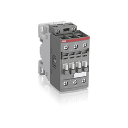
Ordering
1 piece
85364900
Popular Downloads
Dimensions
45 mm
86 mm
86 mm
0.35 kg
Technical
3
0
0
0
3P
IEC/EN 60947-1, IEC/EN 60947-4-1, UL 60335-2-40 LZGH2 A2L, UL 60947-4-1, CSA C22.2 No. 60335-2-40 LZGH2 A2L, CSA C22.2 No. 60947-4-1
Main Circuit 690 V
Control Circuit 50 / 60 Hz
Main Circuit 50 / 60 Hz
Control Circuit 50 / 60 Hz
Main Circuit 50 / 60 Hz
acc. to IEC 60947-4-1, Open Contactors Θ = 40 °C 50 A
(690 V) 40 °C 50 A
(690 V) 60 °C 42 A
(690 V) 70 °C 37 A
(690 V) 40 °C 50 A
(690 V) 60 °C 42 A
(690 V) 70 °C 37 A
(415 V) 60 °C 38 A
(440 V) 60 °C 38 A
(500 V) 60 °C 33 A
(690 V) 60 °C 24 A
(380 / 400 V) 60 °C 38 A
(220 / 230 / 240 V) 60 °C 40 A
(415 V) 60 °C 38 A
(440 V) 60 °C 38 A
(500 V) 60 °C 33 A
(690 V) 60 °C 24 A
(380 / 400 V) 60 °C 38 A
(220 / 230 / 240 V) 60 °C 40 A
(415 V) 60 °C 38 A
(440 V) 60 °C 38 A
(500 V) 60 °C 33 A
(690 V) 60 °C 24 A
(380 / 400 V) 60 °C 38 A
(220 / 230 / 240 V) 60 °C 40 A
(415 V) 60 °C 38 A
(440 V) 60 °C 38 A
(500 V) 60 °C 33 A
(690 V) 60 °C 24 A
(380 / 400 V) 60 °C 38 A
(220 / 230 / 240 V) 60 °C 40 A
(110 V) 2 Poles in Series, 40 °C 50 A
(110 V) 2 Poles in Series, 60 °C 42 A
(110 V) 2 Poles in Series, 70 °C 37 A
(110 V) 3 Poles in Series, 40 °C 50 A
(110 V) 3 Poles in Series, 60 °C 42 A
(110 V) 3 Poles in Series, 70 °C 37 A
(220 V) 3 Poles in Series, 40 °C 50 A
(220 V) 3 Poles in Series, 60 °C 42 A
(220 V) 3 Poles in Series, 70 °C 37 A
(72 V) 1-Pole, 40 °C 50 A
(72 V) 1-Pole, 60 °C 42 A
(72 V) 1-Pole, 70 °C 37 A
(72 V) 2 Poles in Series, 40 °C 50 A
(72 V) 2 Poles in Series, 60 °C 42 A
(72 V) 2 Poles in Series, 70 °C 37 A
(72 V) 3 Poles in Series, 40 °C 50 A
(72 V) 3 Poles in Series, 60 °C 42 A
(72 V) 3 Poles in Series, 70 °C 37 A
(110 V) 2 Poles in Series, 40 °C 50 A
(110 V) 2 Poles in Series, 60 °C 42 A
(110 V) 2 Poles in Series, 70 °C 37 A
(110 V) 3 Poles in Series, 40 °C 50 A
(110 V) 3 Poles in Series, 60 °C 42 A
(110 V) 3 Poles in Series, 70 °C 37 A
(220 V) 3 Poles in Series, 40 °C 50 A
(220 V) 3 Poles in Series, 60 °C 42 A
(220 V) 3 Poles in Series, 70 °C 37 A
(72 V) 1-Pole, 40 °C 50 A
(110 V) 2 Poles in Series, 40 °C 50 A
(110 V) 2 Poles in Series, 60 °C 42 A
(110 V) 2 Poles in Series, 70 °C 37 A
(110 V) 3 Poles in Series, 40 °C 50 A
(110 V) 3 Poles in Series, 60 °C 42 A
(110 V) 3 Poles in Series, 70 °C 37 A
(220 V) 3 Poles in Series, 40 °C 50 A
(220 V) 3 Poles in Series, 60 °C 42 A
(220 V) 3 Poles in Series, 70 °C 37 A
(72 V) 1-Pole, 40 °C 50 A
(72 V) 1-Pole, 60 °C 42 A
(72 V) 1-Pole, 70 °C 37 A
(72 V) 2 Poles in Series, 40 °C 50 A
(72 V) 2 Poles in Series, 60 °C 42 A
(72 V) 2 Poles in Series, 70 °C 37 A
(72 V) 3 Poles in Series, 40 °C 50 A
(72 V) 3 Poles in Series, 60 °C 42 A
(72 V) 3 Poles in Series, 70 °C 37 A
(110 V) 2 Poles in Series, 40 °C 50 A
(110 V) 2 Poles in Series, 60 °C 42 A
(110 V) 2 Poles in Series, 70 °C 37 A
(110 V) 3 Poles in Series, 40 °C 50 A
(110 V) 3 Poles in Series, 60 °C 42 A
(110 V) 3 Poles in Series, 70 °C 37 A
(220 V) 3 Poles in Series, 40 °C 50 A
(220 V) 3 Poles in Series, 60 °C 42 A
(220 V) 3 Poles in Series, 70 °C 37 A
(72 V) 1-Pole, 40 °C 50 A
(110 V) 2 Poles in Series, 40 °C 50 A
(110 V) 2 Poles in Series, 60 °C 42 A
(110 V) 2 Poles in Series, 70 °C 37 A
(110 V) 3 Poles in Series, 40 °C 50 A
(110 V) 3 Poles in Series, 60 °C 42 A
(110 V) 3 Poles in Series, 70 °C 37 A
(220 V) 3 Poles in Series, 40 °C 25 A
(220 V) 3 Poles in Series, 60 °C 25 A
(220 V) 3 Poles in Series, 70 °C 25 A
(72 V) 1-Pole, 40 °C 25 A
(72 V) 1-Pole, 60 °C 25 A
(72 V) 1-Pole, 70 °C 25 A
(72 V) 2 Poles in Series, 40 °C 50 A
(72 V) 2 Poles in Series, 60 °C 42 A
(72 V) 2 Poles in Series, 70 °C 37 A
(72 V) 3 Poles in Series, 40 °C 50 A
(72 V) 3 Poles in Series, 60 °C 42 A
(72 V) 3 Poles in Series, 70 °C 37 A
(110 V) 2 Poles in Series, 40 °C 50 A
(110 V) 2 Poles in Series, 60 °C 42 A
(110 V) 2 Poles in Series, 70 °C 37 A
(110 V) 3 Poles in Series, 40 °C 50 A
(110 V) 3 Poles in Series, 60 °C 42 A
(110 V) 3 Poles in Series, 70 °C 37 A
(220 V) 3 Poles in Series, 40 °C 25 A
(220 V) 3 Poles in Series, 60 °C 25 A
(220 V) 3 Poles in Series, 70 °C 25 A
(72 V) 1-Pole, 40 °C 25 A
(400 V) 18.5 kW
(415 V) 18.5 kW
(440 V) 22 kW
(500 V) 22 kW
(690 V) 22 kW
(380 / 400 V) 18.5 kW
(220 / 230 / 240 V) 11 kW
(400 V) 18.5 kW
(415 V) 18.5 kW
(440 V) 22 kW
(500 V) 22 kW
(690 V) 22 kW
(380 / 400 V) 18.5 kW
(220 / 230 / 240 V) 11 kW
(415 V) 18.5 kW
(440 V) 22 kW
(500 V) 22 kW
(690 V) 22 kW
(380 / 400 V) 18.5 kW
(220 / 230 / 240 V) 11 kW
(415 V) 18.5 kW
(440 V) 22 kW
(500 V) 22 kW
(690 V) 22 kW
(380 / 400 V) 18.5 kW
(220 / 230 / 240 V) 11 kW
at 40 °C Ambient Temp, in Free Air, from a Cold State 10 s 350 A
at 40 °C Ambient Temp, in Free Air, from a Cold State 15 min 50 A
at 40 °C Ambient Temp, in Free Air, from a Cold State 1 min 150 A
at 40 °C Ambient Temp, in Free Air, from a Cold State 1 s 700 A
at 40 °C Ambient Temp, in Free Air, from a Cold State 30 s 225 A
at 40 °C Ambient Temp, in Free Air, from a Cold State 10 s 350 A
at 40 °C Ambient Temp, in Free Air, from a Cold State 15 min 50 A
at 40 °C Ambient Temp, in Free Air, from a Cold State 1 min 150 A
at 40 °C Ambient Temp, in Free Air, from a Cold State 1 s 700 A
at 40 °C Ambient Temp, in Free Air, from a Cold State 30 s 225 A
cos phi=0.45 (cos phi=0.35 for Ie > 100 A) at 440 V 500 A
cos phi=0.45 (cos phi=0.35 for Ie > 100 A) at 690 V 200 A
cos phi=0.45 (cos phi=0.35 for Ie > 100 A) at 440 V 500 A
cos phi=0.45 (cos phi=0.35 for Ie > 100 A) at 690 V 200 A
acc. to IEC 60947-4-1 690 V
acc. to UL/CSA 600 V
acc. to IEC 60947-4-1 690 V
acc. to UL/CSA 600 V
6 kV
(AC-1) 600 cycles per hour
(AC-2 / AC-4) 150 cycles per hour
(AC-3) 1200 cycles per hour
(AC-1) 600 cycles per hour
(AC-2 / AC-4) 150 cycles per hour
(AC-3) 1200 cycles per hour
3600 cycles per hour
50 Hz 100 ... 250 V
60 Hz 100 ... 250 V
DC Operation 100 ... 250 V
50 Hz 100 ... 250 V
60 Hz 100 ... 250 V
DC Operation 100 ... 250 V
at Rated Operating Conditions AC-1 per Pole 2.4 W
at Rated Operating Conditions AC-3 per Pole 1.3 W
at Rated Operating Conditions AC-1 per Pole 2.4 W
at Rated Operating Conditions AC-3 per Pole 1.3 W
Between Coil De-energization and NC Contact Closing 13 ... 98 ms
Between Coil De-energization and NO Contact Opening 11 ... 95 ms
Between Coil Energization and NC Contact Opening 38 ... 90 ms
Between Coil Energization and NO Contact Closing 40 ... 95 ms
Between Coil De-energization and NC Contact Closing 13 ... 98 ms
Between Coil De-energization and NO Contact Opening 11 ... 95 ms
Between Coil Energization and NC Contact Opening 38 ... 90 ms
Between Coil Energization and NO Contact Closing 40 ... 95 ms
TH35-15 (35 x 15 mm Mounting Rail) acc. to IEC 60715
TH35-7.5 (35 x 7.5 mm Mounting Rail) acc. to IEC 60715
TH35-15 (35 x 15 mm Mounting Rail) acc. to IEC 60715
TH35-7.5 (35 x 7.5 mm Mounting Rail) acc. to IEC 60715
2 x M4 Screws Placed Diagonally
Flexible with Ferrule 1/2x 1.5 ... 10 mm²
Flexible with Insulated Ferrule 1x 1.5 ... 10 mm²
Flexible with Insulated Ferrule 2x 1.5 ... 4 mm²
Rigid Solid 1/2x 2.5 ... 4 mm²
Rigid Stranded 1/2x 2.5 ... 10 mm²
Flexible with Ferrule 1/2x 1.5 ... 10 mm²
Flexible with Insulated Ferrule 1x 1.5 ... 10 mm²
Flexible with Insulated Ferrule 2x 1.5 ... 4 mm²
Rigid Solid 1/2x 2.5 ... 4 mm²
Rigid Stranded 1/2x 2.5 ... 10 mm²
Flexible with Ferrule 1/2x 0.75 ... 2.5 mm²
Flexible with Insulated Ferrule 1x 0.75 ... 2.5 mm²
Flexible with Insulated Ferrule 2x 0.75 ... 1.5 mm²
Rigid Solid 1/2x 1 ... 2.5 mm²
Rigid Stranded 1/2x 1 ... 2.5 mm²
Flexible with Ferrule 1/2x 0.75 ... 2.5 mm²
Flexible with Insulated Ferrule 1x 0.75 ... 2.5 mm²
Flexible with Insulated Ferrule 2x 0.75 ... 1.5 mm²
Rigid Solid 1/2x 1 ... 2.5 mm²
Rigid Stranded 1/2x 1 ... 2.5 mm²
Control Circuit 10 mm
Main Circuit 14 mm
Control Circuit 10 mm
Main Circuit 14 mm
acc. to IEC 60529, IEC 60947-1, EN 60529 Coil Terminals IP20
acc. to IEC 60529, IEC 60947-1, EN 60529 Main Terminals IP20
acc. to IEC 60529, IEC 60947-1, EN 60529 Coil Terminals IP20
acc. to IEC 60529, IEC 60947-1, EN 60529 Main Terminals IP20
Control Circuit 1.2 N·m
Main Circuit 2.5 N·m
Control Circuit 1.2 N·m
Main Circuit 2.5 N·m
Screw Terminals
Block Contactor
Technical UL/CSA
Main Circuit 600 V
(600 V AC) 50 A
(120 V AC) Single Phase 2 hp
(200 ... 208 V AC) Three Phase 10 hp
(220 ... 240 V AC) Three Phase 10 hp
(240 V AC) Single Phase 5 hp
(440 ... 480 V AC) Three Phase 25 hp
(550 ... 600 V AC) Three Phase 30 hp
(120 V AC) Single Phase 2 hp
(200 ... 208 V AC) Three Phase 10 hp
(220 ... 240 V AC) Three Phase 10 hp
(240 V AC) Single Phase 5 hp
(440 ... 480 V AC) Three Phase 25 hp
(550 ... 600 V AC) Three Phase 30 hp
Rigid Solid 1/2x 14-10 AWG
Rigid Stranded 1/2x 14-8 AWG
Rigid Solid 1/2x 14-10 AWG
Rigid Stranded 1/2x 14-8 AWG
Rigid Solid 1/2x 18-14 AWG
Rigid Stranded 1/2x 18-14 AWG
Rigid Solid 1/2x 18-14 AWG
Rigid Stranded 1/2x 18-14 AWG
Control Circuit 11 in·lb
Main Circuit 22 in·lb
Control Circuit 11 in·lb
Main Circuit 22 in·lb
(120 V AC) Single Phase 24 A
(200 ... 208 V AC) Three Phase 32.2 A
(220 ... 240 V AC) Three Phase 28 A
(240 V AC) Single Phase 28 A
(440 ... 480 V AC) Three Phase 34 A
(550 ... 600 V AC) Three Phase 32 A
(120 V AC) Single Phase 24 A
(200 ... 208 V AC) Three Phase 32.2 A
(220 ... 240 V AC) Three Phase 28 A
(240 V AC) Single Phase 28 A
(440 ... 480 V AC) Three Phase 34 A
(550 ... 600 V AC) Three Phase 32 A
Environmental
Close to Contactor Fitted with Thermal O/L Relay -25 ... 60 °C
Close to Contactor without Thermal O/L Relay -40 ... 70 °C
Close to Contactor for Storage -60 ... +80 °C
Close to Contactor Fitted with Thermal O/L Relay -25 ... 60 °C
Close to Contactor without Thermal O/L Relay -40 ... 70 °C
Close to Contactor for Storage -60 ... +80 °C
Category B according to IEC 60947-1 Annex Q
Without Derating 3000 m
Closed, Shock Direction: B1 25 g
Open, Shock Direction: B1 5 g
Shock Direction: A 30 g
Shock Direction: B2 15 g
Shock Direction: C1 25 g
Shock Direction: C2 25 g
Closed, Shock Direction: B1 25 g
Open, Shock Direction: B1 5 g
Shock Direction: A 30 g
Shock Direction: B2 15 g
Shock Direction: C1 25 g
Shock Direction: C2 25 g
4g Closed Position & 2g Open position 5 ... 300 Hz
3
Material Compliance
Following EU Directive 2011/65/EU and Amendment 2015/863 July 22, 2019
776a0087-3e6f-43fc-ae63-c6269378eec2 China
Business To Business
5. Small Equipment (No External Dimension More Than 50 cm)
ABB EcoSolutions
Recycled Cardboard - 86 %
Recycled Metal - 28 %
Certificates and Declarations
Container Information
box 1 piece
87 mm
87 mm
47 mm
0.35 kg
3471523114739
box 21 piece
250 mm
300 mm
315 mm
15.75 kg
External Classifications and Standards
Q
EC000066 - Power contactor, AC switching
EC000066 - Power contactor, AC switching
EC000066 - Power contactor, AC switching
V11.0 : 27371003
39121529
4758 >> Iec Contactors
3706320
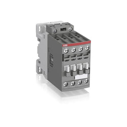
Ordering
1 piece
85364900
Popular Downloads
Dimensions
45 mm
101 mm
86 mm
0.4 kg
Technical
4
0
0
0
4P
IEC/EN 60947-1, IEC/EN 60947-4-1, UL 60335-2-40 LZGH2 A2L, UL 60947-1, UL 60947-4-1, CSA C22.2 No. 60335-2-40 LZGH2 A2L, CAN/CSA C22.2 No.60947-1, CAN/CSA C22.2 No.60947-4-1
Main Circuit 690 V
Control Circuit 50 / 60 Hz
Main Circuit 50 / 60 Hz
Control Circuit 50 / 60 Hz
Main Circuit 50 / 60 Hz
acc. to IEC 60947-4-1, Open Contactors Θ = 40 °C 55 A
(690 V) 40 °C 55 A
(690 V) 60 °C 45 A
(690 V) 70 °C 37 A
(690 V) 40 °C 55 A
(690 V) 60 °C 45 A
(690 V) 70 °C 37 A
(415 V) 60 °C 21.2 A
(440 V) 60 °C 20 A
(500 V) 60 °C 17.6 A
(690 V) 60 °C 10.5 A
(380 / 400 V) 60 °C 22 A
(220 / 230 / 240 V) 60 °C 23.2 A
(415 V) 60 °C 21.2 A
(440 V) 60 °C 20 A
(500 V) 60 °C 17.6 A
(690 V) 60 °C 10.5 A
(380 / 400 V) 60 °C 22 A
(220 / 230 / 240 V) 60 °C 23.2 A
(110 V) 2 Poles in Series, 40 °C 55 A
(110 V) 2 Poles in Series, 60 °C 45 A
(110 V) 2 Poles in Series, 70 °C 37 A
(110 V) 3 Poles in Series, 40 °C 55 A
(110 V) 3 Poles in Series, 60 °C 45 A
(110 V) 3 Poles in Series, 70 °C 37 A
(110 V) 4 Poles in Series, 40 °C 55 A
(110 V) 4 Poles in Series, 60 °C 45 A
(110 V) 4 Poles in Series, 70 °C 37 A
(220 V) 3 Poles in Series, 40 °C 55 A
(220 V) 3 Poles in Series, 60 °C 45 A
(220 V) 3 Poles in Series, 70 °C 37 A
(220 V) 4 Poles in Series, 40 °C 55 A
(220 V) 4 Poles in Series, 60 °C 45 A
(220 V) 4 Poles in Series, 70 °C 37 A
(72 V) 1-Pole, 40 °C 55 A
(72 V) 1-Pole, 60 °C 45 A
(72 V) 1-Pole, 70 °C 37 A
(72 V) 2 Poles in Series, 40 °C 55 A
(72 V) 2 Poles in Series, 60 °C 45 A
(72 V) 2 Poles in Series, 70 °C 37 A
(72 V) 3 Poles in Series, 40 °C 55 A
(72 V) 3 Poles in Series, 60 °C 45 A
(72 V) 3 Poles in Series, 70 °C 37 A
(72 V) 4 Poles in Series, 40 °C 55 A
(72 V) 4 Poles in Series, 60 °C 45 A
(72 V) 4 Poles in Series, 70 °C 37 A
(110 V) 2 Poles in Series, 40 °C 55 A
(110 V) 2 Poles in Series, 60 °C 45 A
(110 V) 2 Poles in Series, 70 °C 37 A
(110 V) 3 Poles in Series, 40 °C 55 A
(110 V) 3 Poles in Series, 60 °C 45 A
(110 V) 3 Poles in Series, 70 °C 37 A
(110 V) 4 Poles in Series, 40 °C 55 A
(110 V) 4 Poles in Series, 60 °C 45 A
(110 V) 4 Poles in Series, 70 °C 37 A
(220 V) 3 Poles in Series, 40 °C 55 A
(400 V) 11 kW
(415 V) 11 kW
(440 V) 11 kW
(500 V) 11 kW
(690 V) 9 kW
(220 / 230 / 240 V) 5.5 kW
(400 V) 11 kW
(415 V) 11 kW
(440 V) 11 kW
(500 V) 11 kW
(690 V) 9 kW
(220 / 230 / 240 V) 5.5 kW
at 40 °C Ambient Temp, in Free Air, from a Cold State 10 s 300 A
at 40 °C Ambient Temp, in Free Air, from a Cold State 15 min 55 A
at 40 °C Ambient Temp, in Free Air, from a Cold State 1 min 150 A
at 40 °C Ambient Temp, in Free Air, from a Cold State 1 s 450 A
at 40 °C Ambient Temp, in Free Air, from a Cold State 30 s 225 A
at 40 °C Ambient Temp, in Free Air, from a Cold State 10 s 300 A
at 40 °C Ambient Temp, in Free Air, from a Cold State 15 min 55 A
at 40 °C Ambient Temp, in Free Air, from a Cold State 1 min 150 A
at 40 °C Ambient Temp, in Free Air, from a Cold State 1 s 450 A
at 40 °C Ambient Temp, in Free Air, from a Cold State 30 s 225 A
acc. to IEC 60947-4-1 690 V
acc. to UL/CSA 600 V
acc. to IEC 60947-4-1 690 V
acc. to UL/CSA 600 V
6 kV
(AC-1) 600 cycles per hour
3600 cycles per hour
50 Hz 100 ... 250 V
60 Hz 100 ... 250 V
DC Operation 100 ... 250 V
50 Hz 100 ... 250 V
60 Hz 100 ... 250 V
DC Operation 100 ... 250 V
at Rated Operating Conditions AC-1 per Pole 2.3 W
at Rated Operating Conditions AC-3 per Pole 0.42 W
at Rated Operating Conditions AC-1 per Pole 2.3 W
at Rated Operating Conditions AC-3 per Pole 0.42 W
Between Coil De-energization and NC Contact Closing 13 ... 98 ms
Between Coil De-energization and NO Contact Opening 11 ... 95 ms
Between Coil Energization and NC Contact Opening 38 ... 90 ms
Between Coil Energization and NO Contact Closing 40 ... 95 ms
Between Coil De-energization and NC Contact Closing 13 ... 98 ms
Between Coil De-energization and NO Contact Opening 11 ... 95 ms
Between Coil Energization and NC Contact Opening 38 ... 90 ms
Between Coil Energization and NO Contact Closing 40 ... 95 ms
TH35-15 (35 x 15 mm Mounting Rail) acc. to IEC 60715
TH35-7.5 (35 x 7.5 mm Mounting Rail) acc. to IEC 60715
TH35-15 (35 x 15 mm Mounting Rail) acc. to IEC 60715
TH35-7.5 (35 x 7.5 mm Mounting Rail) acc. to IEC 60715
2 x M4 Screws Placed Diagonally
Flexible with Ferrule 1/2x 1.5 ... 16 mm²
Flexible with Insulated Ferrule 1/2x 1.5 ... 16 mm²
Rigid Solid 1/2x 1.5 ... 4 mm²
Rigid Stranded 1/2x 1.5 ... 16 mm²
Flexible with Ferrule 1/2x 1.5 ... 16 mm²
Flexible with Insulated Ferrule 1/2x 1.5 ... 16 mm²
Rigid Solid 1/2x 1.5 ... 4 mm²
Rigid Stranded 1/2x 1.5 ... 16 mm²
Flexible with Ferrule 1/2x 0.75 ... 2.5 mm²
Flexible with Insulated Ferrule 1x 0.75 ... 2.5 mm²
Flexible with Insulated Ferrule 2x 0.75 ... 1.5 mm²
Rigid Solid 1/2x 1 ... 2.5 mm²
Rigid Stranded 1/2x 1 ... 2.5 mm²
Flexible with Ferrule 1/2x 0.75 ... 2.5 mm²
Flexible with Insulated Ferrule 1x 0.75 ... 2.5 mm²
Flexible with Insulated Ferrule 2x 0.75 ... 1.5 mm²
Rigid Solid 1/2x 1 ... 2.5 mm²
Rigid Stranded 1/2x 1 ... 2.5 mm²
Control Circuit 10 mm
Main Circuit 12 mm
Control Circuit 10 mm
Main Circuit 12 mm
acc. to IEC 60529, IEC 60947-1, EN 60529 Coil Terminals IP20
acc. to IEC 60529, IEC 60947-1, EN 60529 Main Terminals IP20
acc. to IEC 60529, IEC 60947-1, EN 60529 Coil Terminals IP20
acc. to IEC 60529, IEC 60947-1, EN 60529 Main Terminals IP20
Control Circuit 1.2 N·m
Main Circuit 2.5 N·m
Control Circuit 1.2 N·m
Main Circuit 2.5 N·m
Screw Terminals
Block Contactor
Technical UL/CSA
Main Circuit 600 V
(600 V AC) 55 A
Rigid Solid 1/2x 16-10 AWG
Rigid Stranded 1/2x 16-6 AWG
Rigid Solid 1/2x 16-10 AWG
Rigid Stranded 1/2x 16-6 AWG
Rigid Solid 1/2x 18-14 AWG
Rigid Stranded 1/2x 18-14 AWG
Rigid Solid 1/2x 18-14 AWG
Rigid Stranded 1/2x 18-14 AWG
Control Circuit 11 in·lb
Main Circuit 22 in·lb
Control Circuit 11 in·lb
Main Circuit 22 in·lb
Environmental
Close to Contactor for Storage -60 ... +80 °C
Near Contactor for Operation in Free Air -40 ... 70 °C
Close to Contactor for Storage -60 ... +80 °C
Near Contactor for Operation in Free Air -40 ... 70 °C
Category B according to IEC 60947-1 Annex Q
Without Derating 3000 m
Closed, Shock Direction: B1 25 g
Open, Shock Direction: B1 5 g
Shock Direction: A 30 g
Shock Direction: B2 15 g
Shock Direction: C1 25 g
Shock Direction: C2 25 g
Closed, Shock Direction: B1 25 g
Open, Shock Direction: B1 5 g
Shock Direction: A 30 g
Shock Direction: B2 15 g
Shock Direction: C1 25 g
Shock Direction: C2 25 g
4g Closed Position & 2g Open position 5 ... 300 Hz
3
Material Compliance
Following EU Directive 2011/65/EU and Amendment 2015/863 July 22, 2019
Business To Business
5. Small Equipment (No External Dimension More Than 50 cm)
ABB EcoSolutions
Recycled Cardboard - 86 %
Recycled Metal - 28 %
Certificates and Declarations
Container Information
box 1 piece
87 mm
103 mm
47 mm
0.4 kg
3471523116139
box 18 piece
250 mm
300 mm
315 mm
14.4 kg
External Classifications and Standards
Q
EC000066 - Power contactor, AC switching
EC000066 - Power contactor, AC switching
EC000066 - Power contactor, AC switching
V11.0 : 27371003
39121529
4758 >> Iec Contactors
3705843
AF38Z-30-00-22 CONTACTOR 3P 38A 48-130V AC / DC

AF38Z-40-00-22 CONTACTOR 4P 55A AC1 48-130VAC / DC

Ordering
1 piece
85364900
Popular Downloads
Dimensions
45 mm
101 mm
86 mm
0.4 kg
Technical
4
0
0
0
4P
IEC/EN 60947-1, IEC/EN 60947-4-1, UL 60335-2-40 LZGH2 A2L, UL 60947-1, UL 60947-4-1, CSA C22.2 No. 60335-2-40 LZGH2 A2L, CAN/CSA C22.2 No.60947-1, CAN/CSA C22.2 No.60947-4-1
Main Circuit 690 V
Control Circuit 50 / 60 Hz
Main Circuit 50 / 60 Hz
Control Circuit 50 / 60 Hz
Main Circuit 50 / 60 Hz
acc. to IEC 60947-4-1, Open Contactors Θ = 40 °C 55 A
(690 V) 40 °C 55 A
(690 V) 60 °C 45 A
(690 V) 70 °C 37 A
(690 V) 40 °C 55 A
(690 V) 60 °C 45 A
(690 V) 70 °C 37 A
(415 V) 60 °C 21.2 A
(440 V) 60 °C 20 A
(500 V) 60 °C 17.6 A
(690 V) 60 °C 10.5 A
(380 / 400 V) 60 °C 22 A
(220 / 230 / 240 V) 60 °C 23.2 A
(415 V) 60 °C 21.2 A
(440 V) 60 °C 20 A
(500 V) 60 °C 17.6 A
(690 V) 60 °C 10.5 A
(380 / 400 V) 60 °C 22 A
(220 / 230 / 240 V) 60 °C 23.2 A
(110 V) 2 Poles in Series, 40 °C 55 A
(110 V) 2 Poles in Series, 60 °C 45 A
(110 V) 2 Poles in Series, 70 °C 37 A
(110 V) 3 Poles in Series, 40 °C 55 A
(110 V) 3 Poles in Series, 60 °C 45 A
(110 V) 3 Poles in Series, 70 °C 37 A
(110 V) 4 Poles in Series, 40 °C 55 A
(110 V) 4 Poles in Series, 60 °C 45 A
(110 V) 4 Poles in Series, 70 °C 37 A
(220 V) 3 Poles in Series, 40 °C 55 A
(220 V) 3 Poles in Series, 60 °C 45 A
(220 V) 3 Poles in Series, 70 °C 37 A
(220 V) 4 Poles in Series, 40 °C 55 A
(220 V) 4 Poles in Series, 60 °C 45 A
(220 V) 4 Poles in Series, 70 °C 37 A
(72 V) 1-Pole, 40 °C 55 A
(72 V) 1-Pole, 60 °C 45 A
(72 V) 1-Pole, 70 °C 37 A
(72 V) 2 Poles in Series, 40 °C 55 A
(72 V) 2 Poles in Series, 60 °C 45 A
(72 V) 2 Poles in Series, 70 °C 37 A
(72 V) 3 Poles in Series, 40 °C 55 A
(72 V) 3 Poles in Series, 60 °C 45 A
(72 V) 3 Poles in Series, 70 °C 37 A
(72 V) 4 Poles in Series, 40 °C 55 A
(72 V) 4 Poles in Series, 60 °C 45 A
(72 V) 4 Poles in Series, 70 °C 37 A
(110 V) 2 Poles in Series, 40 °C 55 A
(110 V) 2 Poles in Series, 60 °C 45 A
(110 V) 2 Poles in Series, 70 °C 37 A
(110 V) 3 Poles in Series, 40 °C 55 A
(110 V) 3 Poles in Series, 60 °C 45 A
(110 V) 3 Poles in Series, 70 °C 37 A
(110 V) 4 Poles in Series, 40 °C 55 A
(110 V) 4 Poles in Series, 60 °C 45 A
(110 V) 4 Poles in Series, 70 °C 37 A
(220 V) 3 Poles in Series, 40 °C 55 A
(400 V) 11 kW
(415 V) 11 kW
(440 V) 11 kW
(500 V) 11 kW
(690 V) 9 kW
(220 / 230 / 240 V) 5.5 kW
(400 V) 11 kW
(415 V) 11 kW
(440 V) 11 kW
(500 V) 11 kW
(690 V) 9 kW
(220 / 230 / 240 V) 5.5 kW
at 40 °C Ambient Temp, in Free Air, from a Cold State 10 s 300 A
at 40 °C Ambient Temp, in Free Air, from a Cold State 15 min 55 A
at 40 °C Ambient Temp, in Free Air, from a Cold State 1 min 150 A
at 40 °C Ambient Temp, in Free Air, from a Cold State 1 s 450 A
at 40 °C Ambient Temp, in Free Air, from a Cold State 30 s 225 A
at 40 °C Ambient Temp, in Free Air, from a Cold State 10 s 300 A
at 40 °C Ambient Temp, in Free Air, from a Cold State 15 min 55 A
at 40 °C Ambient Temp, in Free Air, from a Cold State 1 min 150 A
at 40 °C Ambient Temp, in Free Air, from a Cold State 1 s 450 A
at 40 °C Ambient Temp, in Free Air, from a Cold State 30 s 225 A
acc. to IEC 60947-4-1 690 V
acc. to UL/CSA 600 V
acc. to IEC 60947-4-1 690 V
acc. to UL/CSA 600 V
6 kV
(AC-1) 600 cycles per hour
3600 cycles per hour
50 Hz 250 ... 500 V
60 Hz 250 ... 500 V
DC Operation 250 ... 500 V
50 Hz 250 ... 500 V
60 Hz 250 ... 500 V
DC Operation 250 ... 500 V
at Rated Operating Conditions AC-1 per Pole 2.3 W
at Rated Operating Conditions AC-3 per Pole 0.42 W
at Rated Operating Conditions AC-1 per Pole 2.3 W
at Rated Operating Conditions AC-3 per Pole 0.42 W
Between Coil De-energization and NC Contact Closing 13 ... 98 ms
Between Coil De-energization and NO Contact Opening 11 ... 95 ms
Between Coil Energization and NC Contact Opening 38 ... 90 ms
Between Coil Energization and NO Contact Closing 40 ... 95 ms
Between Coil De-energization and NC Contact Closing 13 ... 98 ms
Between Coil De-energization and NO Contact Opening 11 ... 95 ms
Between Coil Energization and NC Contact Opening 38 ... 90 ms
Between Coil Energization and NO Contact Closing 40 ... 95 ms
TH35-15 (35 x 15 mm Mounting Rail) acc. to IEC 60715
TH35-7.5 (35 x 7.5 mm Mounting Rail) acc. to IEC 60715
TH35-15 (35 x 15 mm Mounting Rail) acc. to IEC 60715
TH35-7.5 (35 x 7.5 mm Mounting Rail) acc. to IEC 60715
2 x M4 Screws Placed Diagonally
Flexible with Ferrule 1/2x 1.5 ... 16 mm²
Flexible with Insulated Ferrule 1/2x 1.5 ... 16 mm²
Rigid Solid 1/2x 1.5 ... 4 mm²
Rigid Stranded 1/2x 1.5 ... 16 mm²
Flexible with Ferrule 1/2x 1.5 ... 16 mm²
Flexible with Insulated Ferrule 1/2x 1.5 ... 16 mm²
Rigid Solid 1/2x 1.5 ... 4 mm²
Rigid Stranded 1/2x 1.5 ... 16 mm²
Flexible with Ferrule 1/2x 0.75 ... 2.5 mm²
Flexible with Insulated Ferrule 1x 0.75 ... 2.5 mm²
Flexible with Insulated Ferrule 2x 0.75 ... 1.5 mm²
Rigid Solid 1/2x 1 ... 2.5 mm²
Rigid Stranded 1/2x 1 ... 2.5 mm²
Flexible with Ferrule 1/2x 0.75 ... 2.5 mm²
Flexible with Insulated Ferrule 1x 0.75 ... 2.5 mm²
Flexible with Insulated Ferrule 2x 0.75 ... 1.5 mm²
Rigid Solid 1/2x 1 ... 2.5 mm²
Rigid Stranded 1/2x 1 ... 2.5 mm²
Control Circuit 10 mm
Main Circuit 12 mm
Control Circuit 10 mm
Main Circuit 12 mm
acc. to IEC 60529, IEC 60947-1, EN 60529 Coil Terminals IP20
acc. to IEC 60529, IEC 60947-1, EN 60529 Main Terminals IP20
acc. to IEC 60529, IEC 60947-1, EN 60529 Coil Terminals IP20
acc. to IEC 60529, IEC 60947-1, EN 60529 Main Terminals IP20
Control Circuit 1.2 N·m
Main Circuit 2.5 N·m
Control Circuit 1.2 N·m
Main Circuit 2.5 N·m
Screw Terminals
Block Contactor
Technical UL/CSA
Main Circuit 600 V
(600 V AC) 55 A
Rigid Solid 1/2x 16-10 AWG
Rigid Stranded 1/2x 16-6 AWG
Rigid Solid 1/2x 16-10 AWG
Rigid Stranded 1/2x 16-6 AWG
Rigid Solid 1/2x 18-14 AWG
Rigid Stranded 1/2x 18-14 AWG
Rigid Solid 1/2x 18-14 AWG
Rigid Stranded 1/2x 18-14 AWG
Control Circuit 11 in·lb
Main Circuit 22 in·lb
Control Circuit 11 in·lb
Main Circuit 22 in·lb
Environmental
Close to Contactor for Storage -60 ... +80 °C
Near Contactor for Operation in Free Air -40 ... 70 °C
Close to Contactor for Storage -60 ... +80 °C
Near Contactor for Operation in Free Air -40 ... 70 °C
Category B according to IEC 60947-1 Annex Q
Without Derating 3000 m
Closed, Shock Direction: B1 25 g
Open, Shock Direction: B1 5 g
Shock Direction: A 30 g
Shock Direction: B2 15 g
Shock Direction: C1 25 g
Shock Direction: C2 25 g
Closed, Shock Direction: B1 25 g
Open, Shock Direction: B1 5 g
Shock Direction: A 30 g
Shock Direction: B2 15 g
Shock Direction: C1 25 g
Shock Direction: C2 25 g
4g Closed Position & 2g Open position 5 ... 300 Hz
3
Material Compliance
Following EU Directive 2011/65/EU and Amendment 2015/863 July 22, 2019
Business To Business
5. Small Equipment (No External Dimension More Than 50 cm)
ABB EcoSolutions
Recycled Cardboard - 86 %
Recycled Metal - 28 %
Certificates and Declarations
Container Information
box 1 piece
87 mm
103 mm
47 mm
0.4 kg
3471523115347
box 18 piece
250 mm
300 mm
315 mm
14.4 kg
External Classifications and Standards
Q
EC000066 - Power contactor, AC switching
EC000066 - Power contactor, AC switching
EC000066 - Power contactor, AC switching
V11.0 : 27371003
39121529
4758 >> Iec Contactors
3705839
3211521
Main category name:Drives - Motors - Circuits Protection Vendor:ABB